Embed Size (px)
Citation preview
schwarz-selinger.ppt, © Thomas Schwarz-Selinger, 05. März 2008
Max-Planck-Institutfür Plasmaphysik
Entfernung von Kohlenwasserstoffschichten aus Gräben und Spalten mittels Sauerstoffplasmen:
Das delikate Zusammenspiel von Physik und Chemie
Thomas Schwarz-Selinger, Wolfgang Jacob
XV. ErfahrungsaustauschOberflächentechnologie mit Plasma- und Ionenstrahlprozessen
Mühlleithen 05. März 2008
schwarz-selinger.ppt, © Thomas Schwarz-Selinger, 05. März 2008
Max-Planck-Institutfür Plasmaphysik
Removal of hydrocarbons from gaps with oxygen plasmas:
the delicate interplay between physics and chemistry
Thomas Schwarz-Selinger, Wolfgang Jacob
XV. ErfahrungsaustauschOberflächentechnologie mit Plasma- und Ionenstrahlprozessen
Mühlleithen 05. März 2008
schwarz-selinger.ppt, © Thomas Schwarz-Selinger, 05. März 2008
motivation
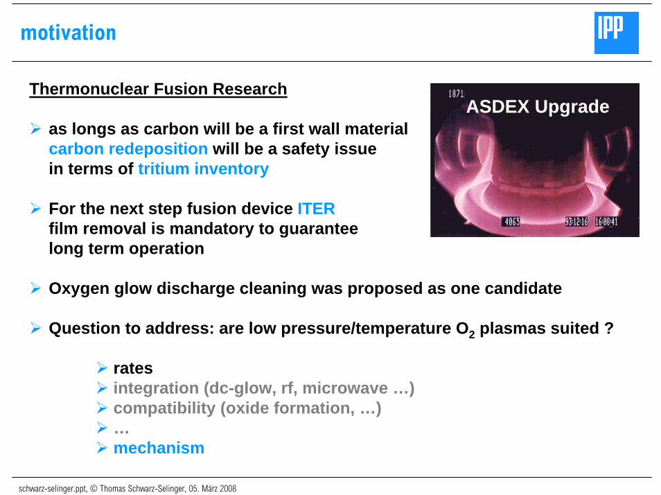
Thermonuclear Fusion Research
as longs as carbon will be a first wall material carbon redeposition will be a safety issuein terms of tritium inventory
For the next step fusion device ITERfilm removal is mandatory to guaranteelong term operation
Oxygen glow discharge cleaning was proposed as one candidate
Question to address: are low pressure/temperature O2 plasmas suited ?
ratesintegration (dc-glow, rf, microwave …)compatibility (oxide formation, …)…mechanism
ASDEX Upgrade
schwarz-selinger.ppt, © Thomas Schwarz-Selinger, 05. März 2008
challenge for film removal: gaps everywhere
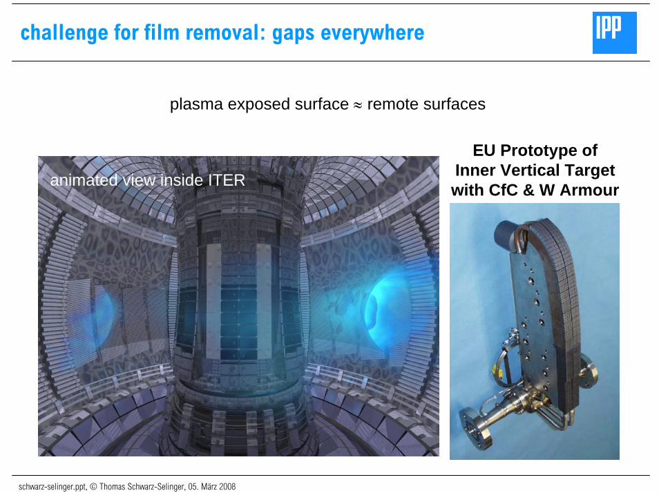
plasma exposed surface ≈ remote surfaces
EU Prototype ofInner Vertical Targetwith CfC & W Armouranimated view inside ITER
schwarz-selinger.ppt, © Thomas Schwarz-Selinger, 05. März 2008
erosion of carbon in tile gap structures by oxygen plasmas
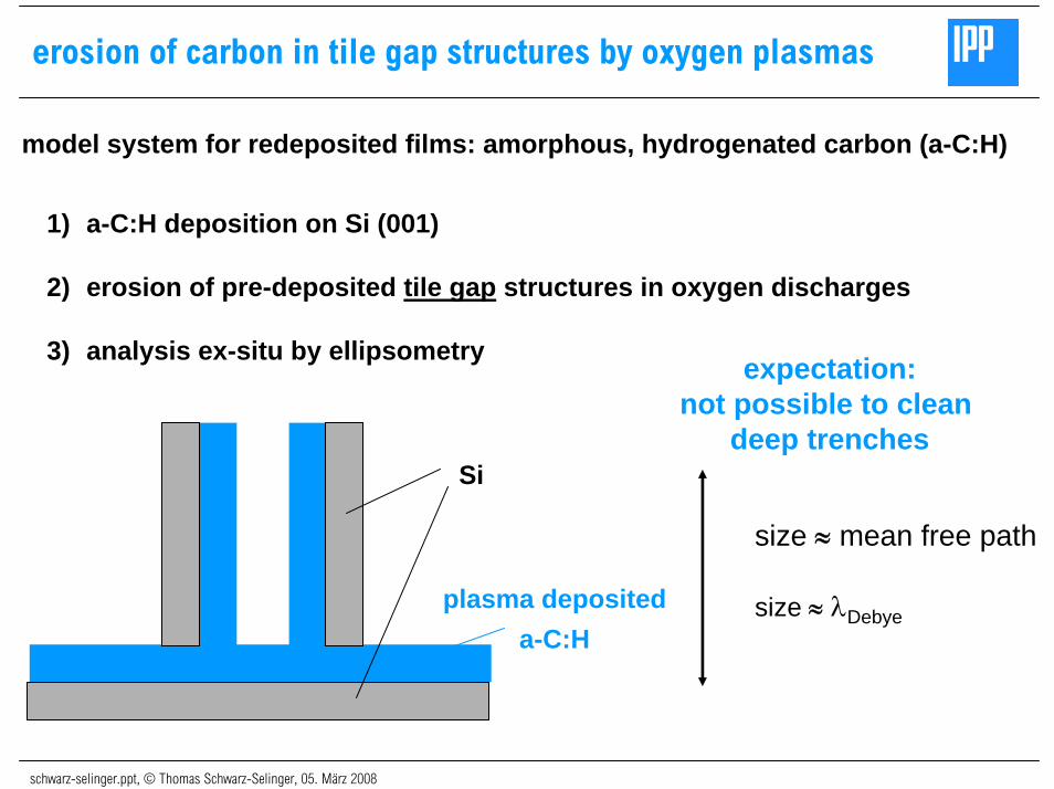
1) a-C:H deposition on Si (001)
2) erosion of pre-deposited tile gap structures in oxygen discharges
3) analysis ex-situ by ellipsometry expectation:not possible to clean
deep trenches
plasma depositeda-C:H
Si
model system for redeposited films: amorphous, hydrogenated carbon (a-C:H)
size ≈ mean free path
size ≈ λDebye
schwarz-selinger.ppt, © Thomas Schwarz-Selinger, 05. März 2008
erosion of carbon in tile gap structures by oxygen plasmas
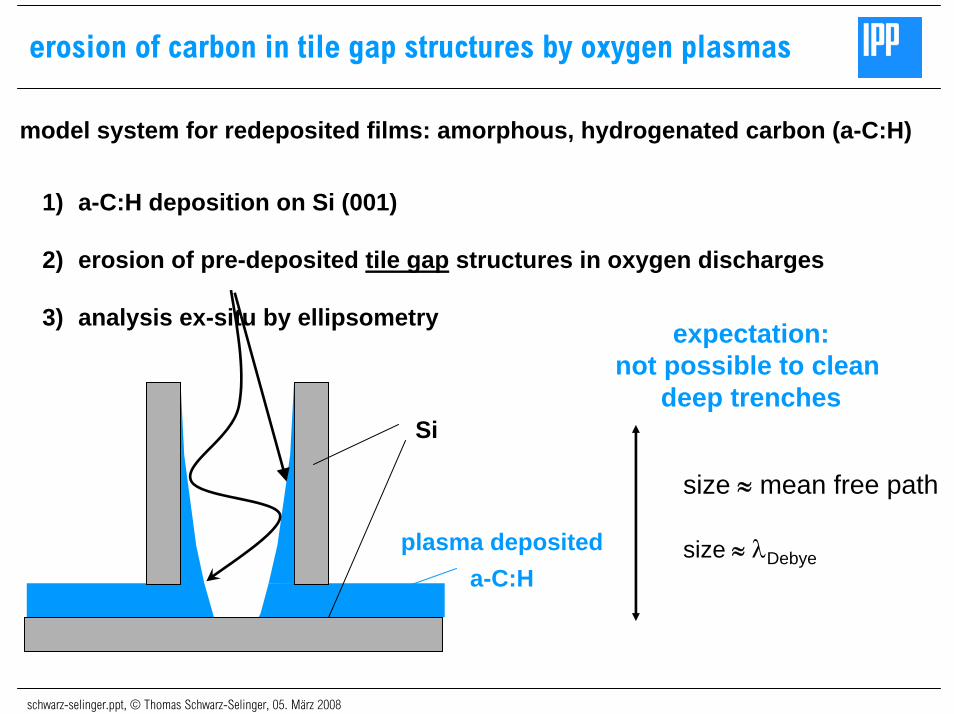
model system for redeposited films: amorphous, hydrogenated carbon (a-C:H)
1) a-C:H deposition on Si (001)
2) erosion of pre-deposited tile gap structures in oxygen discharges
3) analysis ex-situ by ellipsometry expectation:not possible to clean
deep trenches
plasma depositeda-C:H
Si
size ≈ mean free path
size ≈ λDebye
schwarz-selinger.ppt, © Thomas Schwarz-Selinger, 05. März 2008
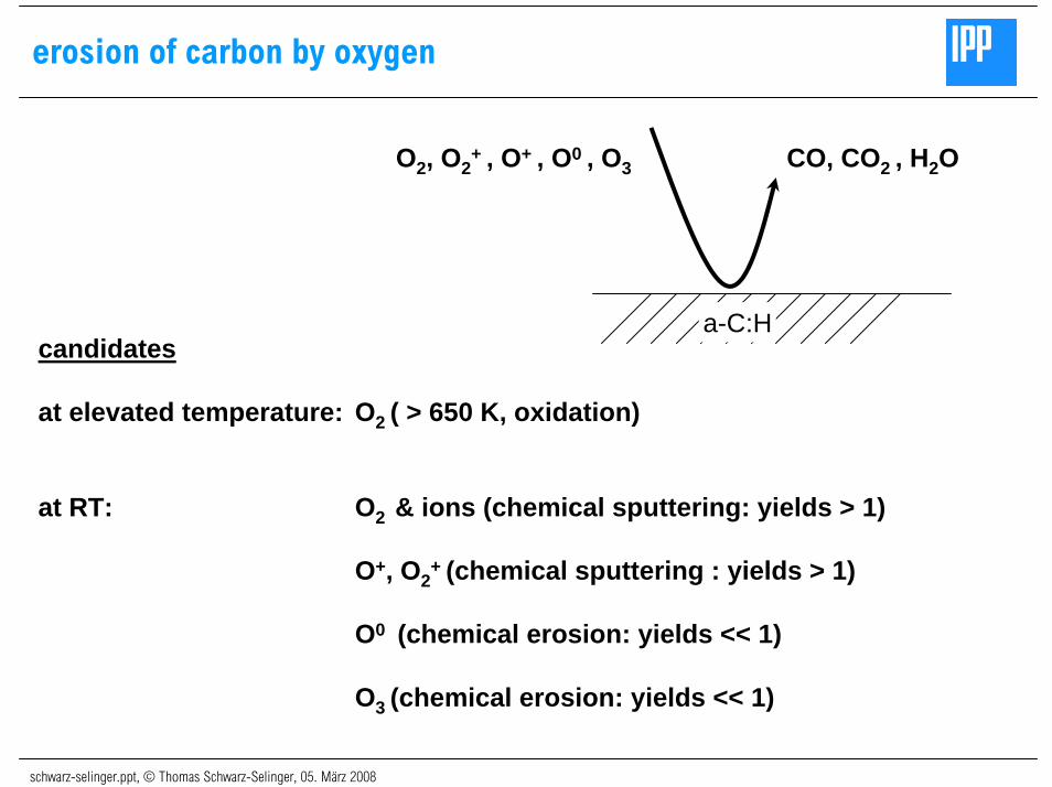
erosion of carbon by oxygen
CO, CO2 , H2O O2, O2+ , O+ , O0 , O3
candidates
at elevated temperature: O2 ( > 650 K, oxidation)
at RT: O2 & ions (chemical sputtering: yields > 1)
O+, O2+ (chemical sputtering : yields > 1)
O0 (chemical erosion: yields << 1)
O3 (chemical erosion: yields << 1)
a-C:H
schwarz-selinger.ppt, © Thomas Schwarz-Selinger, 05. März 2008
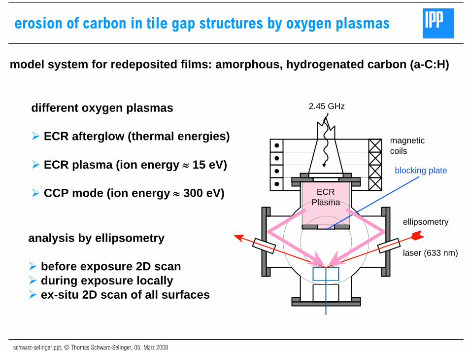
erosion of carbon in tile gap structures by oxygen plasmas
model system for redeposited films: amorphous, hydrogenated carbon (a-C:H)
different oxygen plasmas
ECR afterglow (thermal energies)
ECR plasma (ion energy ≈ 15 eV)
CCP mode (ion energy ≈ 300 eV)
2.45 GHz
magneticcoils
ECRPlasma
ellipsometry
laser (633 nm)
blocking plate
analysis by ellipsometry
before exposure 2D scanduring exposure locallyex-situ 2D scan of all surfaces
schwarz-selinger.ppt, © Thomas Schwarz-Selinger, 05. März 2008
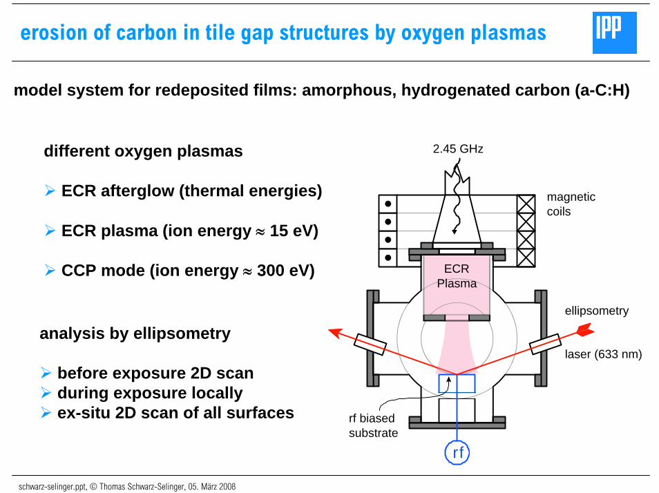
erosion of carbon in tile gap structures by oxygen plasmas
model system for redeposited films: amorphous, hydrogenated carbon (a-C:H)
different oxygen plasmas
ECR afterglow (thermal energies)
ECR plasma (ion energy ≈ 15 eV)
CCP mode (ion energy ≈ 300 eV)
2.45 GHz
magneticcoils
r f
ECRPlasma
ellipsometry
laser (633 nm)
rf biasedsubstrate
analysis by ellipsometry
before exposure 2D scanduring exposure locallyex-situ 2D scan of all surfaces
schwarz-selinger.ppt, © Thomas Schwarz-Selinger, 05. März 2008
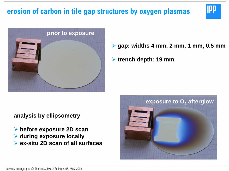
erosion of carbon in tile gap structures by oxygen plasmas
prior to exposure
gap: widths 4 mm, 2 mm, 1 mm, 0.5 mm
trench depth: 19 mm
exposure to O2 afterglow
analysis by ellipsometry
before exposure 2D scanduring exposure locallyex-situ 2D scan of all surfaces
schwarz-selinger.ppt, © Thomas Schwarz-Selinger, 05. März 2008
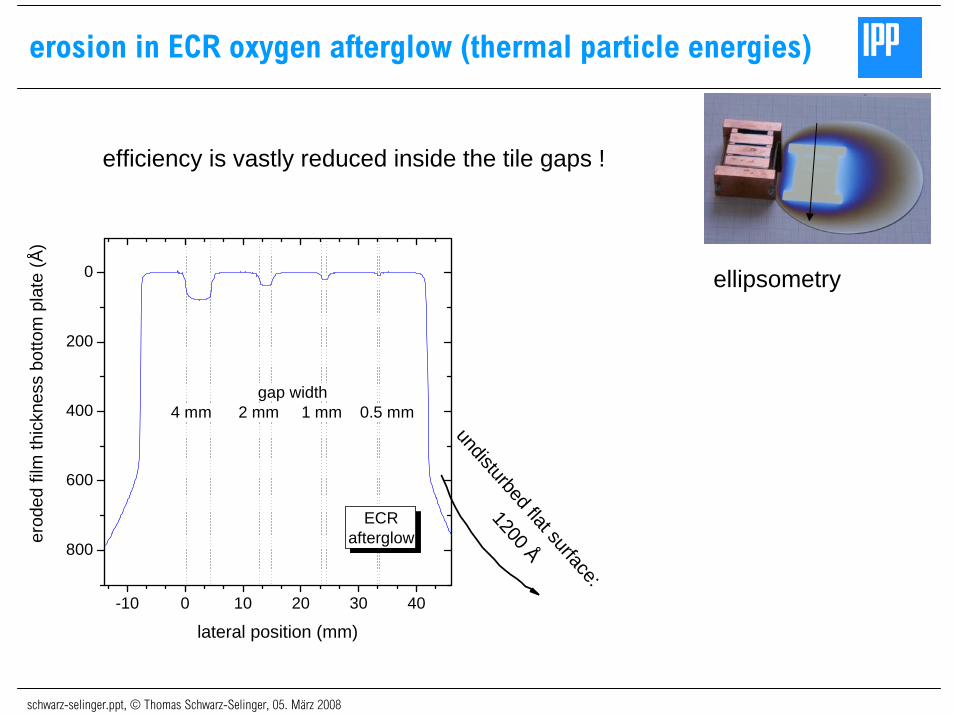
erosion in ECR oxygen afterglow (thermal particle energies)
efficiency is vastly reduced inside the tile gaps !
-10 0 10 20 30 40
800
600
400
200
0
ECRafterglow
erod
ed fi
lm th
ickn
ess
botto
m p
late
(Å)
lateral position (mm)
gap width4 mm 2 mm 1 mm 0.5 mm
undisturbed flat surface:
1200 Å
ellipsometry
schwarz-selinger.ppt, © Thomas Schwarz-Selinger, 05. März 2008
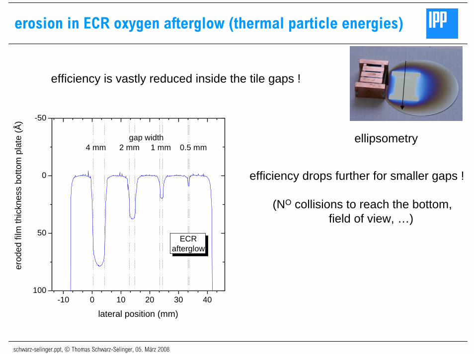
erosion in ECR oxygen afterglow (thermal particle energies)
ellipsometry
efficiency is vastly reduced inside the tile gaps !
-10 0 10 20 30 40100
50
0
-50
ECRafterglow
erod
ed fi
lm th
ickn
ess
botto
m p
late
(Å)
lateral position (mm)
gap width4 mm 2 mm 1 mm 0.5 mm
efficiency drops further for smaller gaps !
(NO collisions to reach the bottom,field of view, …)
schwarz-selinger.ppt, © Thomas Schwarz-Selinger, 05. März 2008
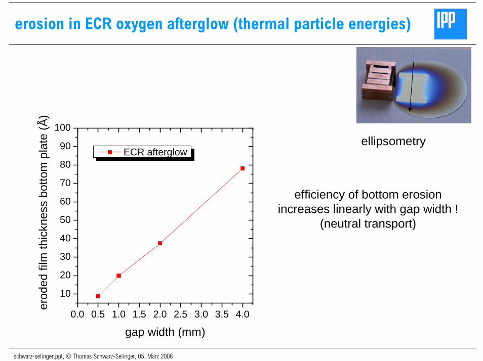
erosion in ECR oxygen afterglow (thermal particle energies)
0.0 0.5 1.0 1.5 2.0 2.5 3.0 3.5 4.0
10
20
30
40
50
60
70
80
90
100
erod
ed fi
lm th
ickn
ess
botto
m p
late
(Å)
gap width (mm)
ECR afterglow
efficiency of bottom erosionincreases linearly with gap width !
(neutral transport)
ellipsometry
schwarz-selinger.ppt, © Thomas Schwarz-Selinger, 05. März 2008
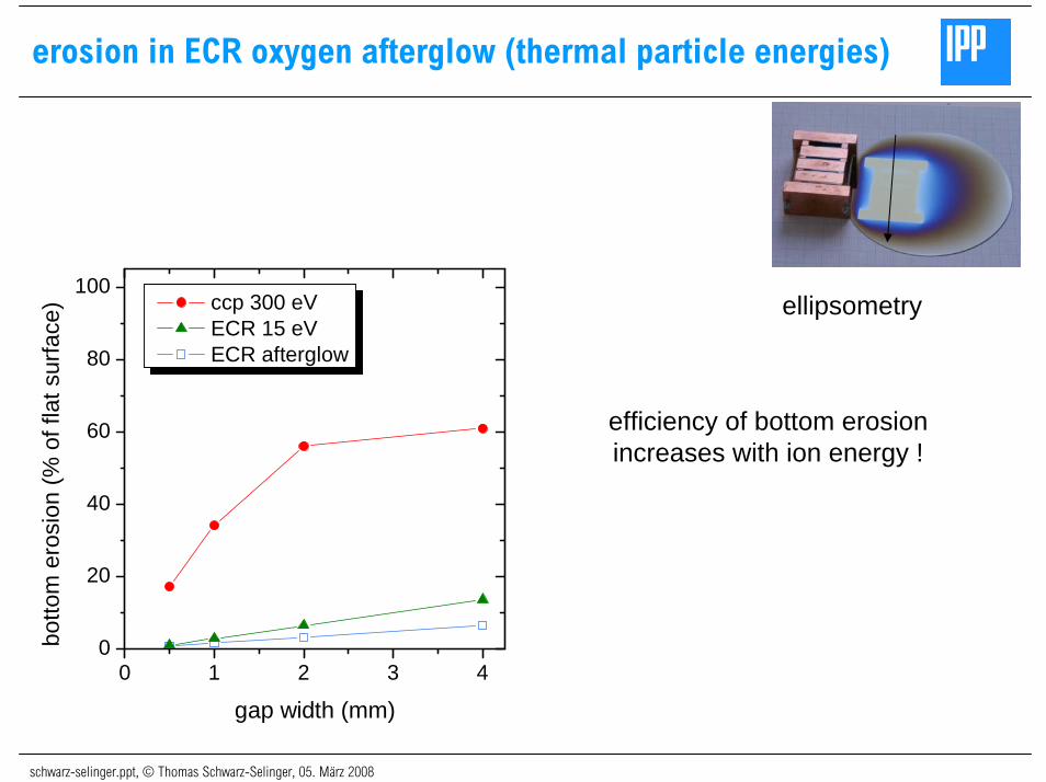
erosion in ECR oxygen afterglow (thermal particle energies)
ellipsometry
0 1 2 3 40
20
40
60
80
100
botto
m e
rosi
on (%
of f
lat s
urfa
ce)
gap width (mm)
ccp 300 eV ECR 15 eV ECR afterglow
efficiency of bottom erosionincreases with ion energy !
schwarz-selinger.ppt, © Thomas Schwarz-Selinger, 05. März 2008
erosion in ECR oxygen afterglow (thermal particle energies)
ellipsometry
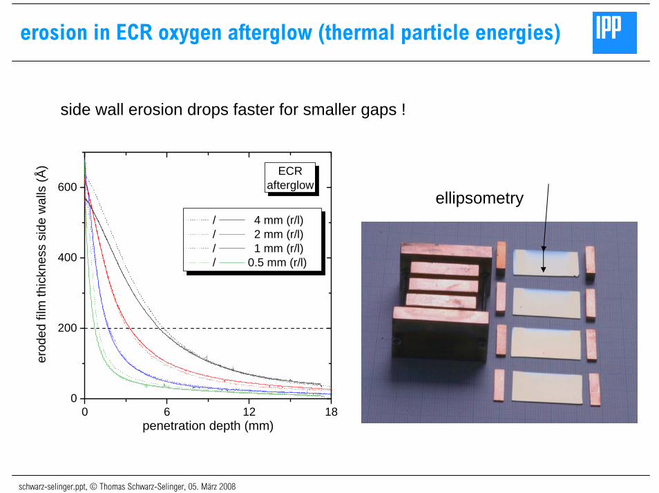
0 6 12 180
200
400
600ECR
afterglow
erod
ed fi
lm th
ickn
ess
side
wal
ls (Å
)
penetration depth (mm)
/ 4 mm (r/l) / 2 mm (r/l) / 1 mm (r/l) / 0.5 mm (r/l)
side wall erosion drops faster for smaller gaps !
schwarz-selinger.ppt, © Thomas Schwarz-Selinger, 05. März 2008
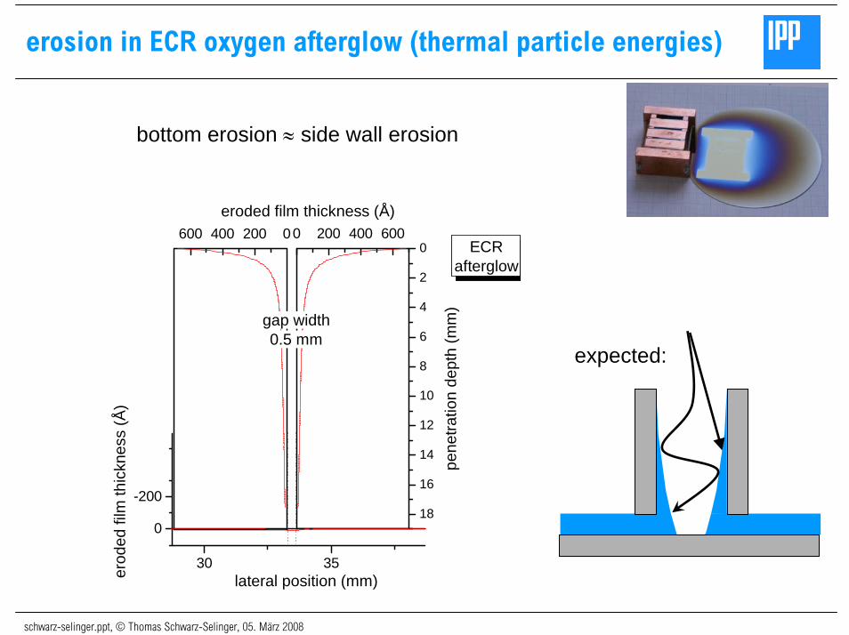
erosion in ECR oxygen afterglow (thermal particle energies)
bottom erosion ≈ side wall erosion
30 35
0
-200
0 200 400 600
18
16
14
12
10
8
6
4
2
0600 400 200 0
erod
ed fi
lm th
ickn
ess
(Å)
lateral position (mm)
gap width0.5 mm
ECRafterglow
pen
etra
tion
dept
h (m
m)
eroded film thickness (Å)
expected:
schwarz-selinger.ppt, © Thomas Schwarz-Selinger, 05. März 2008
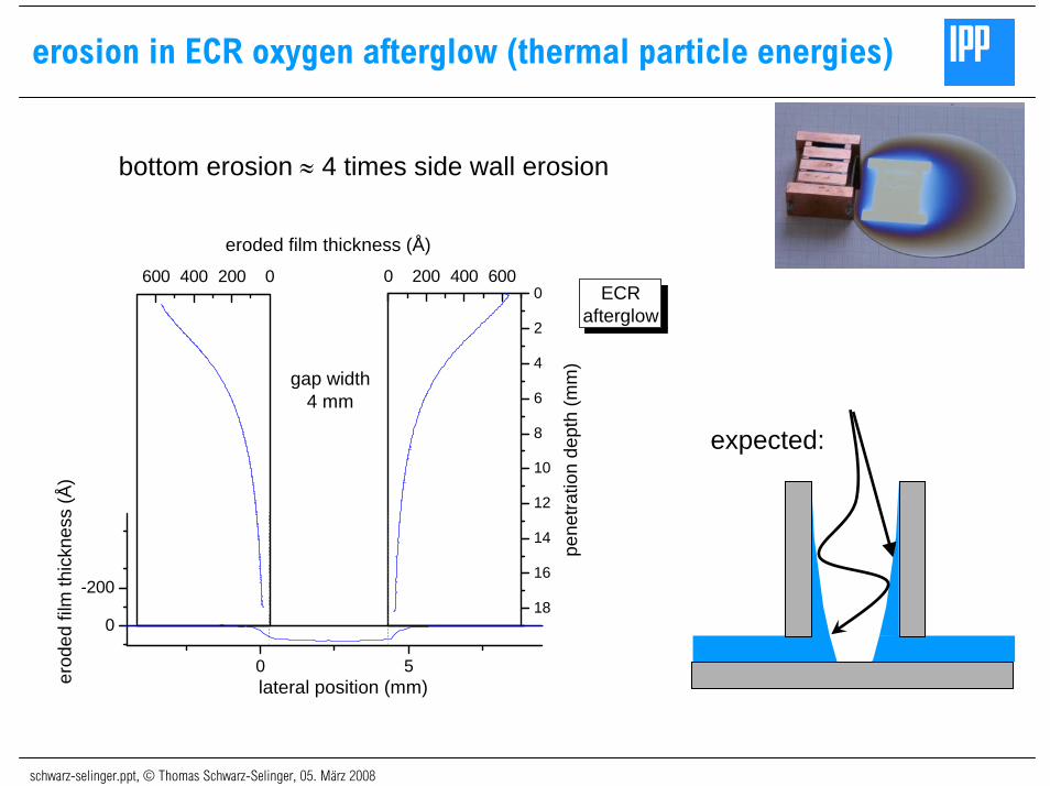
erosion in ECR oxygen afterglow (thermal particle energies)
0 5
0
-200
0 200 400 600
18
16
14
12
10
8
6
4
2
0600 400 200 0
erod
ed fi
lm th
ickn
ess
(Å)
lateral position (mm)
gap width4 mm
ECRafterglow
pen
etra
tion
dept
h (m
m)
eroded film thickness (Å)
expected:
bottom erosion ≈ 4 times side wall erosion

schwarz-selinger.ppt, © Thomas Schwarz-Selinger, 05. März 2008
erosion in ECR oxygen plasma (15 eV ion energy)
bottom erosion ≈ 4 times side wall erosion
0 5
500
250
0
-250
0 250 500 750
18
16
14
12
10
8
6
4
2
0750 500 250 0
erod
ed fi
lm th
ickn
ess
(Å)
lateral position (mm)
gap width4 mm
ECR15 eV
pen
etra
tion
dept
h (m
m)
eroded film thickness (Å)
expected:
schwarz-selinger.ppt, © Thomas Schwarz-Selinger, 05. März 2008
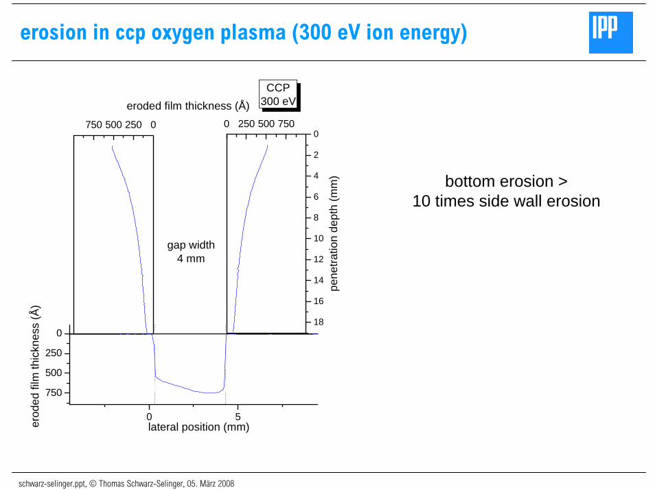
erosion in ccp oxygen plasma (300 eV ion energy)
0 5
750
500
250
0
0 250 500 750
18
16
14
12
10
8
6
4
2
0750 500 250 0
erod
ed fi
lm th
ickn
ess
(Å)
lateral position (mm)
gap width4 mm
CCP300 eV
pen
etra
tion
dept
h (m
m)
eroded film thickness (Å)
bottom erosion > 10 times side wall erosion
schwarz-selinger.ppt, © Thomas Schwarz-Selinger, 05. März 2008
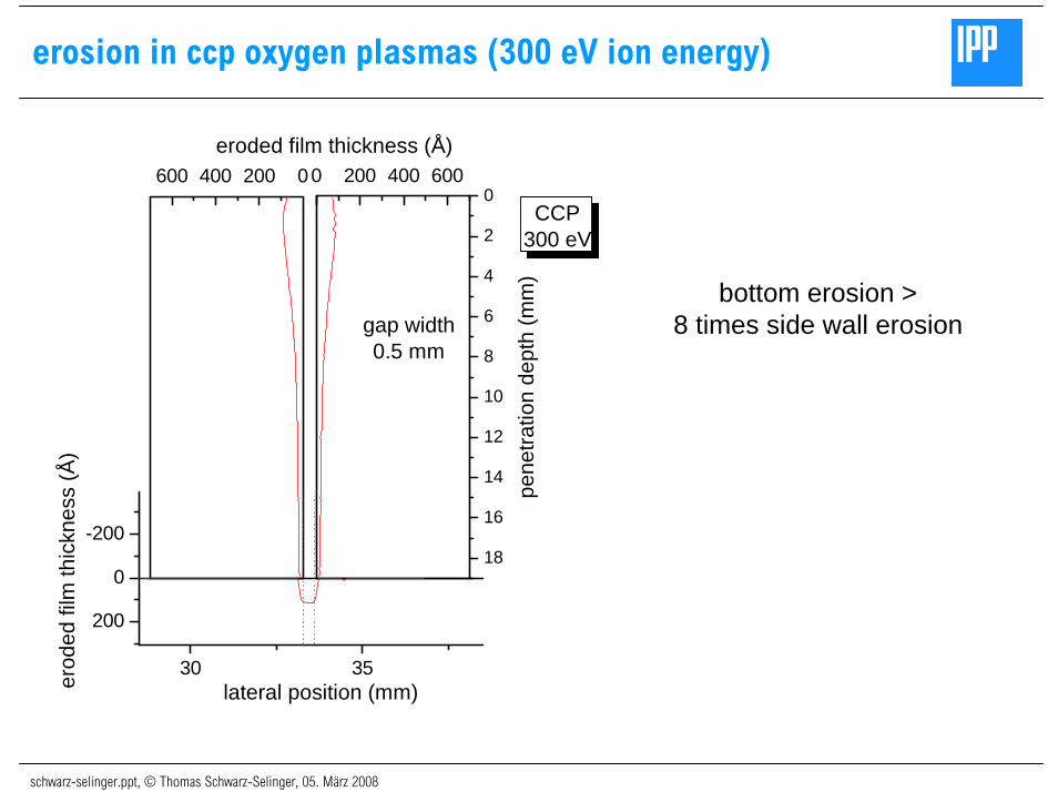
erosion in ccp oxygen plasmas (300 eV ion energy)
30 35
200
0
-200
0 200 400 600
18
16
14
12
10
8
6
4
2
0600 400 200 0
erod
ed fi
lm th
ickn
ess
(Å)
lateral position (mm)
gap width0.5 mm
CCP300 eV
pen
etra
tion
dept
h (m
m)
eroded film thickness (Å)
bottom erosion > 8 times side wall erosion
schwarz-selinger.ppt, © Thomas Schwarz-Selinger, 05. März 2008
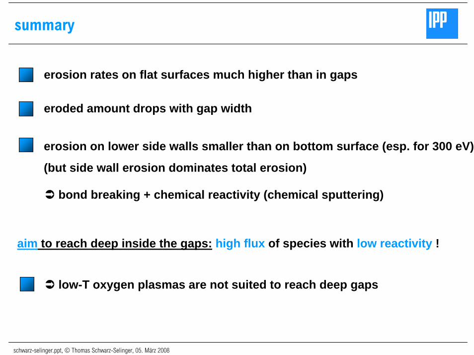
summary
erosion rates on flat surfaces much higher than in gaps
eroded amount drops with gap width
erosion on lower side walls smaller than on bottom surface (esp. for 300 eV)
(but side wall erosion dominates total erosion)
bond breaking + chemical reactivity (chemical sputtering)
aim to reach deep inside the gaps: high flux of species with low reactivity !
low-T oxygen plasmas are not suited to reach deep gaps
schwarz-selinger.ppt, © Thomas Schwarz-Selinger, 05. März 2008
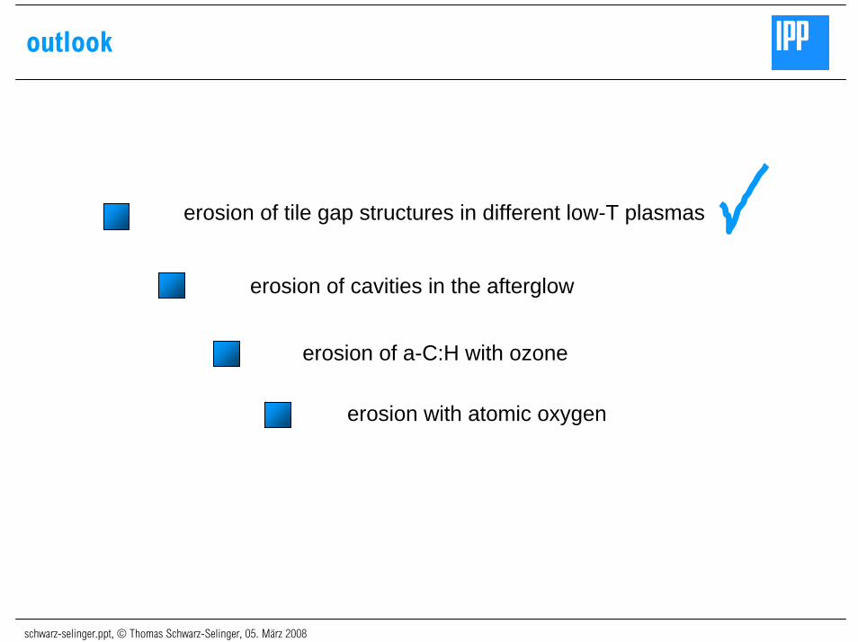
outlook
erosion of tile gap structures in different low-T plasmas
erosion of cavities in the afterglow
erosion of a-C:H with ozone
erosion with atomic oxygen
schwarz-selinger.ppt, © Thomas Schwarz-Selinger, 05. März 2008
Max-Planck-Institutfür Plasmaphysik


![Anlagen 2 bis 7 - landtag.sachsen-anhalt.de · Ing, Salomo + Partner mbH ... DIN 4124, Baugruben und Gräben, Böschungen, Arbeitsraumbreiten, Verbau; ... [28] ZTV SoB StB 04,](https://img.pdfslide.org/doc/110x75/5b9fe47a09d3f242318bc0ba/anlagen-2-bis-7-ing-salomo-partner-mbh-din-4124-baugruben-und-graeben.jpg)