Embed Size (px)
Citation preview
All
right
s re
serv
ed ©
WA
MG
RO
UP
• ELECTRIC EXTERNAL MOTOVIBRATORS
• ELEKTRISCHE AUSSENRÜTTLER
• MOTOVIBRATEURS EXTERNES ELECTRIQUES
• MOTOVIBRATORI ELETTRICI ESTERNI
CATALOGUE No. OL.2050 EX
ISSUEB1
DATE OF LATEST UPDATE
CREATION DATE
09-2011CIRCULATION100
MVE Ex e-Ex tD
II 2 GD Ex e II T3 Ex tD A21 T150°C IP66
INDEX
INHALTSVERZEICHNIS
INDEX
INDICE
10.07
OL.2050EXINDEX
-
-
-
-
1 TECHNICAL CATALOGUE
SCOPE AND IMPORTANCE OF THE MANUAL................................................................DESCRIPTION .....................................................................................................................INDICATIONS FOR THE USE.............................................................................................WARNING..............................................................................................................................WARRANTY CONDITIONS.................................................................................................STORAGE.............................................................................................................................ADJUSTING THE INTENSITY OF VIBRATIONS..............................................................FEATURES..............................................................................................................................2 POLE 3000 rpm 230/400V 50 Hz Three Phase / 3600 rpm 264/460V 60Hz......................4 POLE 3000 rpm 230/400V 50 Hz Three Phase / 3600 rpm 264/460V 60Hz......................6 POLE 3000 rpm 230/400V 50 Hz Three Phase / 3600 rpm 264/460V 60Hz......................8 POLE 750 rpm 230/400V 50 Hz Three Phase / 900 rpm 264/460V 60Hz.........................
TECHNISCHER KATALOG
ZWECK UND BEDEUTUNG DES HANDBUCHS.......................................................BESCHREIBUNG .........................................................................................................ANGABEN ZUM GEBRAUCH.....................................................................................HINWEISE......................................................................................................................GARANTIEBEDINGUNGEN........................................................................................LAGERHALTUNG .........................................................................................................EINSTELLUNG DER VIBRATIONSSTÄRKE...............................................................EIGENSCHAFTEN........................................................................................................2 POLE 3000 rpm 230/400V 50 Hz Three Phase / 3600 rpm 264/460V 60Hz..............4 POLE 3000 rpm 230/400V 50 Hz Three Phase / 3600 rpm 264/460V 60Hz..............6 POLE 3000 rpm 230/400V 50 Hz Three Phase / 3600 rpm 264/460V 60Hz..............8 POLE 750 rpm 230/400V 50 Hz Three Phase / 900 rpm 264/460V 60Hz..................
CATALOGUE TECNIQUE
BUT ET IMPORTANCE DU MANUEL................................................................................DESCRIPTION .....................................................................................................................MODES D’EMPLOI...............................................................................................................RECOMMANDATIONS.........................................................................................................CONDITIONS DE GARANTIE.............................................................................................EMMAGASINAGE ................................................................................................................RÉGLAGE DE L’INTENSITÉ DE LA VIBRATION...............................................................CARCTÉRISTIQUES............................................................................................................2 POLE 3000 rpm 230/400V 50 Hz Three Phase / 3600 rpm 264/460V 60Hz......................4 POLE 3000 rpm 230/400V 50 Hz Three Phase / 3600 rpm 264/460V 60Hz.....................6 POLE 3000 rpm 230/400V 50 Hz Three Phase / 3600 rpm 264/460V 60Hz......................8 POLE 750 rpm 230/400V 50 Hz Three Phase / 900 rpm 264/460V 60Hz.........................
CATALOGO TECNICO
SCOPO ED IMPORTANZA DEL MANUALE.............................................................DESCRIZIONE ..............................................................................................................INDICAZIONI PER L’USO...............................................................................................AVVERTENZE................................................................................................................CONDIZIONI DI GARANZIA.........................................................................................IMMAGAZZINAGGIO ...................................................................................................REGOLAZIONE DELL’INTENSITA’ DELLA VIBRAZIONE.......................................... CARATTERISTICHE.....................................................................................................2 POLE 3000 rpm 230/400V 50 Hz Three Phase / 3600 rpm 264/460V 60Hz..............4 POLE 1500 rpm 230/400V 50 Hz Three Phase / 1800 rpm 264/460V 60Hz..............6 POLE 1000 rpm 230/400V 50 Hz Three Phase / 1200 rpm 264/460V 60Hz..............8 POLE 750 rpm 230/400V 50 Hz Three Phase / 900 rpm 264/460V 60Hz..................
1
T .01 .02 .03 .04→.05 .06 .07 .08→.09 .10 .11→.12 .14→.15 .17→.18 .20→.21
2 MAINTENANCE CATALOGUE
MANUFACTURING DATA....................................................................................................TRANSPORT AND PACKAGING.........................................................................................INSTALLATION......................................................................................................................ELECTRICAL CONNECTIONS...........................................................................................START UP PROCEDURE....................................................................................................LIMITS OF USE.....................................................................................................................MAINTENANCE....................................................................................................................MAINTENANCE - PERIODIC CHECKS..............................................................................RESIDUAL RISKS.................................................................................................................SCRAPPING THE MACHINE/RETURNING......................................................................DECLARATION OF CONFORMITY....................................................................................LIFE OF BEARINGS.............................................................................................................
WARTUNGS KATALOG
KONSTRUKTIONSDATEN............................................................................................TRANSPORT UND VERPACKUNG.............................................................................EINBAU...........................................................................................................................ELEKTRISCHE ANSCLÜSSE.......................................................................................EINSCHALTERFAHREN...............................................................................................EINSATZGRENZEN......................................................................................................WARTUNG.....................................................................................................................WARTUNG - REGELMÄSSIGE KONTROLLEN.........................................................RESTRISIKEN................................................................................................................VERSCHROTTUNG DES GËRATS/RÜCKGABE.......................................................KONFORMITÄTSERKLÄRUNG....................................................................................STANDZEIT DER LAGER.............................................................................................
CATALOGUE D’ENTRETIEN
DONNÉES COSTRUCTIVES..............................................................................................TRANSPORT ET EMBALLAGE............................................................................................INSTALLATION.......................................................................................................................RACCORDEMENT ÉLECTRIQUES...................................................................................PROCÉDURE DE DÉMARRAGE.......................................................................................LIMITES D’EMPLOI ..............................................................................................................ENTRETIEN .........................................................................................................................ENTRETIEN - CONTROLES PERIODIQUES....................................................................RISQUES RESIDUELS.........................................................................................................DEMANTELEMENT DE LA MACHINE/RESTITUTION.....................................................DECLARATION DE CONFORMITE....................................................................................DURÉE DES ROULEMENTS..............................................................................................
CATALOGO DI MANUTENZIONE
DATI COSTRUZIONE....................................................................................................TRASPORTO E IMBALLO.............................................................................................INSTALLAZIONE ............................................................................................................COLLEGAMENTI ELETTRICI......................................................................................PROCEDURA D’AVVIAMENTO...................................................................................LIMITI DI IMPIEGO.........................................................................................................MANUTENZIONE...........................................................................................................MANUTENZIONE - CONTROLLI PERIODICI............................................................RISCHI RESIDUI............................................................................................................ROTTAMAZIONE MACCHINA/RESO MACCHINA....................................................DICHIARAZIONE DI CONFORMITÀ...........................................................................DURATA CUSCINETTI.................................................................................................
2
M .01 .02 .03→.04 .05→.08 .09 .10 .11→.12 .13 .14→.15 .16 .17→.21 .22→.25
SPARE PARTS CATALOGUE
SPARE PARTS.......................................................................................................................
ERSATZTEILKATALOG
ERSATZTEIL...................................................................................................................
CATALOGUE PIECES DE RECHANGE
PIECES DE RECHANGE......................................................................................................
CATALOGO RICAMBI
PEZZI DI RICAMBIO................................................................. ....................................
3
R. .01 →.05
3
R. .01 →.05
MVEExe -Extd
M .01 .02 .03→.04 .05→.08 .09 .10 .11→.12 .13 .14→.15 .16 .17→.21 .22→.25
T .01 .02 .03 .04→.05 .06 .07 .08→.09 .10 .11→.12 .14→.15 .17→.18 .20→.21
TEC
HN
ICA
L C
ATA
LOG
UE
• ELECTRIC EXTERNAL MOTOVIBRATORS TECHNICAL CATALOGUE
• ELEKTRISCHE AUSSENRÜTTLER TECHNISCER KATALOG
• MOTOVIBRATEURS EXTERNES ELECTRIQUES CATALOGUE TECHNIQUE
• MOTOVIBRATORI ELETTRICI ESTERNI CATALOGO TECNICO
All
right
s re
serv
ed ©
WA
MG
RO
UP
1
CATALOGUE No. OL.2050EX T.
ISSUEB1
DATE OF LATEST UPDATE
CREATION DATE
09-2011CIRCULATION100
MVE Ex e-Ex tD
II 2 GD Ex e II T3 Ex tD A21 T150°C IP66
09.11
1
OL.2050EX T.
MVE
-
-
-
-Ex e -Ex tD
SCOPE AND IMPORTANCE OF THE MANUAL
ZWECK UND BEDEUTUNG DES HANDBUCHS
BUT ET IMPORTANCE DU MANUEL
SCOPO E IMPORTANZA DEL MANUALE
La gamma dei vibratori MVE è il risultato di 40 anni di esperienza nel campo della vibrazione con applicazioni nei settori edili ed industriali, sia a livello nazionale che internazionale. La cura nellascelta della componentistica e l’alta precisione delle lavorazioni sono garanzia della durata nel tempo del motovibratore con operazioni di manutenzione estre-mamente semplici e ridotte.
SCOPO ED IMPORTANZA DEL MANUALE Il presente manuale, redatto dal costruttore, è parte integrante del corredo del motovibratore elettri-co; come tale deve assolutamente seguire il motovibratore elettrico fino al suo smantellamento ed essere facilmente reperibile per una rapida consultazione da parte degli operatori interessati e della direzione lavori del cantiere. In caso di cambio di proprietà del motovibratore elettrico, il manuale deve essere consegnato alla nuo-va proprietà. Prima di eseguire qualsiasi operazione con, o sul motovibratore elettrico; il persona-le interessato deve assolutamente ed obbligatoriamente aver letto con la massima attenzione il pre-sente manuale. Qualora il manua-le venga smarrito, sgualcito e tale da non essere completamente leggibile, si deve scaricare una nuova copia dal sito internet della Oli® e verificarne la data dell’ulti-mo aggiornamento. Il presente manuale fornisce avvertenze ed indicazioni relative alle norme di sicurezza per la prevenzione degli infortuni sul lavoro. Vanno in ogni modo, ed in ogni caso, osservate con il massimo scrupolo da parte dei vari operatori le norme di si-curezza poste a loro carico dalle vigenti normative.Eventuali modifiche delle norme di sicurezza che nel tempo doves-sero aver luogo dovranno essere recepite ed attuate.La versione sempre aggiornata del presente catalogo è reperibile sul sito internet www.olivibra.com
La gamme de vibrateurs MVE est le résultat de 40 ans d’expé-rience dans le domaine de la vibration avec des applications dans les secteurs industriels et du bâtiment, tant à échelon national qu’international. Le choix méticuleux des composants et la précision élevée des usinages sont la garantie de la longévité du vibrateur avec des opérations d’entretien extrêmement simples et réduites.
BUT ET IMPORTANCE DU MA-NUELLe présent manuel, rédigé par le constructeur, fait partie intégrante du vibrateur électrique ; comme tel il doit absolument suivre le vibrateur électrique jusqu’à son démantèlement et être conservé à portée de la main afin d’être consultable par les opérateurs concernés et par la direction des travaux du chantier. En cas de changement de propriété du vibrateur électrique, le manuel doit être remis au nouveau pro-priétaire.Avant d’exécuter une quelconque opération avec ou sur le vibrateur électrique, le personnel concerné doit absolument et obligatoire-ment avoir lu très attentivement le présent manuel. Si le manuel a été égaré, abîmé ou n’est plus complètement lisible, télécharger une nouvelle copie sur le site Internet de OLI® et vérifier la date de la dernière mise à jour.Le présent manuel fournit les recommandations et les indica-tions concernant les consignes de sécurité pour la prévention des accidents du travail.Les divers opérateurs doivent, dans tous les cas et toujours, observer avec la plus grande at-tention les consignes de sécurité que la réglementation en vigueur a placé à leur charge.Tou tes mod i f i ca t i ons des consignes de sécurité qui seraient apportées au fil du temps, doivent être adoptées et appliquées.La version toujours mise à jour du présent catalogue est disponible sur le site Internet www.olivibra.com
The range of MVE vibrators is the result of 40 years of experience in the field of vibration with applica-tions in the building and industrial sectors, both at national and inter-national level. Care in the choice of components and high precision machining guarantee long life of the electric vibrator with extremely simple and minimum maintenance operations.
SCOPE AND IMPORTANCE OF THE MANUAL This Manual, prepared by the manufacturer, is an integral part of the electric vibrator kit; it must therefore accompany the electric vibrator right up to its demolition and must be always available, ready at hand, for consultation by the operators concerned and the worksite manager. If the machine changes ownership, the Manual must be handed over to the new owner.Before carrying out any operation with, or on the electric vibrator, the personnel concerned must have read this Manual carefully. If the Manual is lost, damaged or illegible, download the new copy from the Oli® website and verify the date of the last update.This Manual provides warnings and indications regarding the safety regulations for preventing accidents at the worksite.In any case, the various operators must strictly follow the safety rules imposed on them by applicable regulatory standards.Modifications, if any, to the safety regulations must be incorporated and implemented.The constantly updated version of this Manual is available on our websitewww.olivibra.com
Die Baureihe der Unwuchtmoto-ren MVE ist das Ergebnis einer 40-jährigen Erfahrung im Be-reich der Vibrationstechnik, mit Anwendungen im Bausektor und der Industrie, sowohl national als auch international. Die Sorgfalt bei der Auswahl der Komponen-ten und die hohe Genauigkeit der Verarbeitung sind die Garantie für die Haltbarkeit des Unwuchtmo-tors mit einer sehr einfachen und reduzierten Wartung.
ZWECK UND BEDEUTUNG DES HANDBUCHSDieses vom Hersteller erstellte Handbuch ist integrierender Teil des elektrischen Unwuchtmo-tors. Als solches muss es dem elektrischen Unwuchtmotor bis zu seiner Demolierung folgen und für das schnelle Nachschlagen durch die mit seinem Betrieb betrauten Arbeitnehmer und die Baustellenleitung auffindbar sein. Bei einem Besitzerwechsel des elektrischen Unwuchtmotors muss das Handbuch dem neuen Besitzer ausgehändigt werden.Bevor es irgendeine Arbeit an oder mit dem elektrischen Un-wuchtmotor ausführt, muss das fragliche Personal dieses Hand-buch unbedingt mit großer Auf-merksamkeit gelesen haben. Falls das Handbuch verloren geht, be-schädigt wird und in einen solchen Zustand versetzt wird, dass es vollkommen unleserlich ist, muss man sich ein neues Exemplar des Handbuchs von der Webseiten der Firma Oli® herunterladen und das Datum der letzten Aktualisie-rung prüfen.Dieses Handbuch liefert Hin-weise und Angaben zu den Si-cherheitsbestimmungen für die Vermeidung von Unfällen am Arbeitsplatz.Die Sicherheitsbestimmungen, die von den geltenden Normen zu ihren Lasten vorgesehen sind, sind auf jeden Fall seitens der verschiedenen Arbeitnehmer mit einem Höchstmaß an Gewissen-haftigkeit zu beachten.Etwaige Änderungen der Si-cherheitsbestimmungen, die im Laufe der Zeit eintreten, müssen aufgenommen und durchgeführt werden.Die stets auf den neuesten Stand gebrachte Version die-ses Katalog finden Sie auf den Webseitenwww.olivibra.com
01
MVE
-
-
-
-
09.11
1
OL.2050EX T.
Ex e -Ex tD
DESCRIPTION
BESCHREIBUNG
DESCRIPTION
DESCRIZIONE
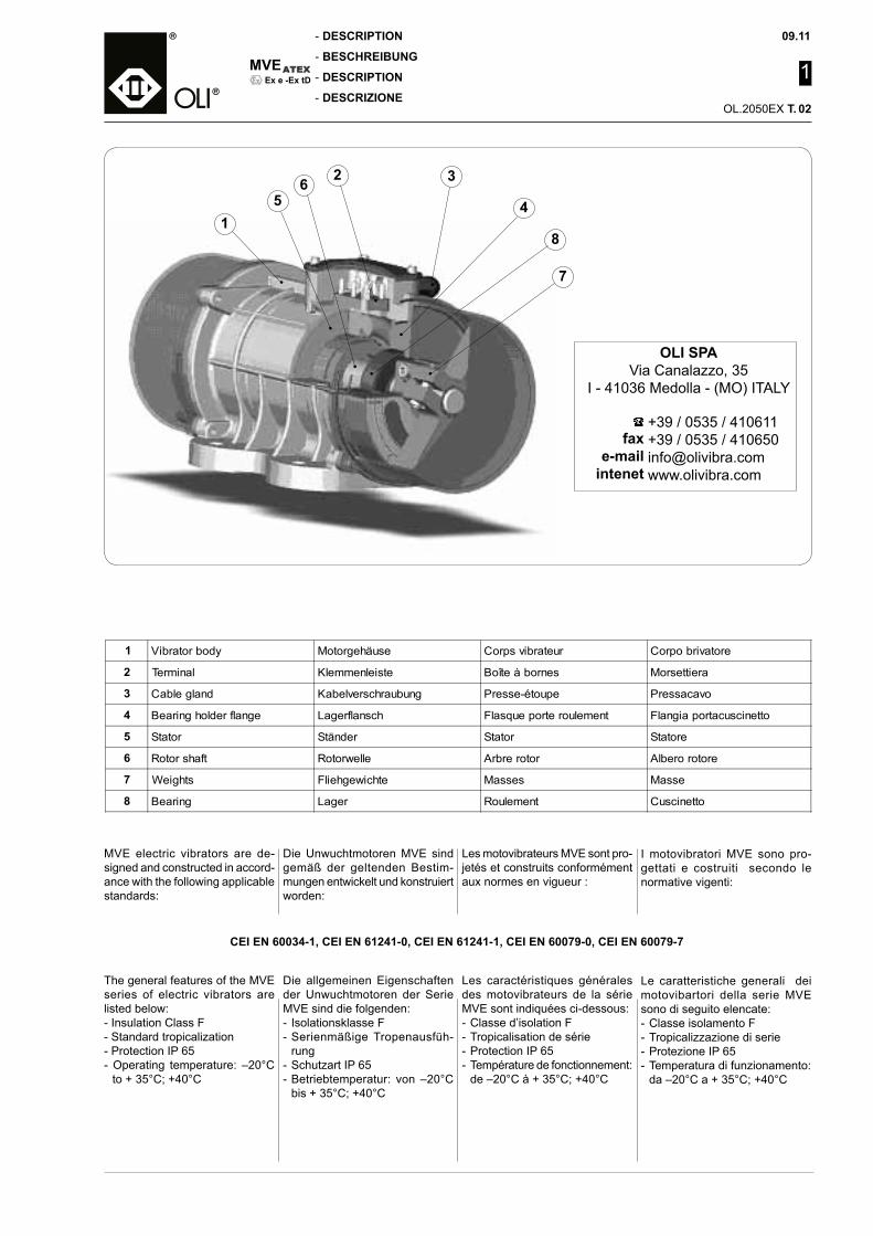
1 Vibrator body Motorgehäuse Corps vibrateur Corpo brivatore
2 Terminal Klemmenleiste Boîte à bornes Morsettiera
3 Cable gland Kabelverschraubung Presse-étoupe Pressacavo
4 Bearing holder flange Lagerflansch Flasque porte roulement Flangia portacuscinetto
5 Stator Ständer Stator Statore
6 Rotor shaft Rotorwelle Arbre rotor Albero rotore
7 Weights Fliehgewichte Masses Masse
8 Bearing Lager Roulement Cuscinetto
I motovibratori MVE sono pro-gettati e costruiti secondo le normative vigenti:
Le caratteristiche generali dei motovibartori della serie MVE sono di seguito elencate:- Classe isolamento F- Tropicalizzazione di serie- Protezione IP 65- Temperatura di funzionamento: da –20°C a + 35°C; +40°C
OLI SPAVia Canalazzo, 35
I - 41036 Medolla - (MO) ITALY
faxe-mail
intenet
+39 / 0535 / 410611+39 / 0535 / [email protected]
MVE electric vibrators are de-signed and constructed in accord-ance with the following applicable standards:
The general features of the MVE series of electric vibrators are listed below:- Insulation Class F- Standard tropicalization- Protection IP 65- Operating temperature: –20°C
to + 35°C; +40°C
Die Unwuchtmotoren MVE sind gemäß der geltenden Bestim-mungen entwickelt und konstruiert worden:
Die allgemeinen Eigenschaften der Unwuchtmotoren der Serie MVE sind die folgenden:- Isolationsklasse F- Serienmäßige Tropenausfüh-
rung- Schutzart IP 65- Betriebtemperatur: von –20°C
bis + 35°C; +40°C
Les motovibrateurs MVE sont pro-jetés et construits conformément aux normes en vigueur :
Les caractéristiques générales des motovibrateurs de la série MVE sont indiquées ci-dessous:- Classe d’isolation F- Tropicalisation de série- Protection IP 65- Température de fonctionnement:
de –20°C à + 35°C; +40°C
1
•
2
•
5
•
6
•
3
•
4
•
8
•
7
•
02
CEI EN 60034-1, CEI EN 61241-0, CEI EN 61241-1, CEI EN 60079-0, CEI EN 60079-7
09.11
1
OL.2050EX T.
MVE
-
-
-
-Ex e -Ex tD
INDICATIONS FOR THE USE
ANGABEN ZUM GEBRAUCH
MODES D’EMPLOI
INDICAZIONI PER L’USO
- Collegare il vibratore alla rete elettrica mediante cavi che abbiano una temperatura di utilizzo corrispondente a quando indicato sulla targhetta del mo-tovibratore. (80°C fino a size 50; 100°C da size 60 a size 90).
- I motovibratori MVE vengono forniti con pressacavi conformi alla direttiva 94/9 CE secondo categoria II2G/D ; nel caso in cui debbano essere sostituiti è necessario utilizzare pressacavi aventi le stesse caratteristiche.
- Il motovibratore elettrico descrit-to in questo manuale è stato pro-gettato e testato per un utilizzo in zone potenzialmente esplo-sive classificate come zona 21 zona 1 secondo la norma EN 50281-3 ed in accordo alla Diret-tiva ATEX 94/9/CE. L’utilizzatore dovrà assicurarsi che il luogo di lavoro all’interno del quale verrà installato il motovibratore elet-trico sia stato adeguatamente messo in sicurezza da un punto di vista di rischio esplosione .
- E’ importante da parte del cliente in fase d’ordine specificare le caratteristiche delle polveri da trattare e anche le temperature di processo.
IMPORTANTE: la versione ATEX del motovibratore elettri-co è stata progettata per ope-rare in atmosfere con presenza di polveri e gas potenzialmente esplosivi
ATTENERSI ALLE INDICAZIONI RIPORTATE NELLA TARGHET-TA: D = dust / polvereG = gas
Per poter operare in condizioni di sicurezza occorre verificare che le polveri trattate abbiano una temperatura di accensio-ne superiore almeno dei 2/3 della temperatura superficiale indicata sulla targhetta del motovibratore (EN 50281-3). (Le massime temperature indicate nel presente manuale ed in tar-ga sui motovibratori sono state calcolate senza considerare l’eventuale presenza di strati di polvere depositate sulle superfici). Il motovibratore elettrico dovrà essere installato con uno spazio circostante sufficiente per effet-tuare le normali operazioni di montaggio/smontaggio, pulitura e manutenzione.
- Connect the vibrator to the elec-tric mains by means of cables having an operating temperature corresponding to that indicated on the electric vibrator rating plate. (100°C up to size 50; 100°C from size 60 to size 90).
- MVE electric vibrators are sup-plied with cable glands con-forming to Directive 94/9 CE according to category II2G/D; for replacement, use cable glands having the same characteristics.
- The electric vibrator described in this Manual is designed and tested for use in potentially ex-plosive zones classified as zone 21 zone 1 according to standard EN 50281-3 and in accordance with ATEX Directive 94/9/CE.
The user must make sure that the workplace in which the elec-tric vibrator is installed is set in safety condition from the point of view of risk of explosion.
- In the order phase, it is neces-sary for the customer to specify the characteristics of the pow-ders handled and the process temperature.
IMPORTANT: the ATEX ver-sion of the electric vibrator is designed for handlingin atmospheres where potentially explosive dusts and gases are present.
FOLLOW THE INDICATIONS GIVEN ON THE RATING PLATE:D = dust / polvereG = gas
To operate in safe conditions, check to make sure the dusts handled have an ignition tem-perature at least 2/3 that of the surface temperature indicated on the electric vibrator rating plate (EN 50281-3).(The maximum temperatures indicated in this Manual and on the electric vibrator rating plate are calculated without taking into consideration the presence of layers of dust, if any, on the surface).The electric vibrator must be installed with sufficient clearance around it to allow assembly/disassembly, cleaning and main-tenance operations.
- Den Stromanschluss des Unwucht-motors mit Kabeln vornehmen, die eine Gebrauchstemperatur haben, die den Angaben auf dem Typenschild des Unwuchtmotors entspricht (80°C bis Baugröße 50; 100°C von Baugröße 60 bis 90).
- Die Unwuchtmotoren MVE wer-den mit Kabelverschraubungen gemäß der Richtlinie 94/9/CE der Kategorie II2G/D geliefert. Falls die Kabelverschraubung ersetzt werden müssen, dazu unbedingt Kabelverschraubungen mit den gleichen Eigenschaften benutzen.
- Der elektrische Unwuchtmotor, der in diesem Handbuch beschrieben wird, wurde für den Einsatz in explosionsgefährdeten Bereichen, die als Zone 21 zone 1 gemäß der Norm EN 50281-3 eingestuft wurden, und in Übereinstimmung mit der ATEX-Richtlinie 94/9/EG entwickelt und getestet.
Der Anwender muss sicherstellen, dass der Arbeitsort, innerhalb des-sen der elektrische Unwuchtmotor installiert wird, hinsichtlich der Explosionsgefahr in einen ange-messenen Sicherheitszustand gebracht worden ist.
- Es ist wichtig, dass der Kunde bei der Bestellung die Eigenschaften der zu behandelnden Stäube und auch die Prozesstemperaturen angibt.
WICHTIG: Die ATEX-Version des elektrischen Unwuchtmotors ist für den Einsatz in Bereichen mit explosionsgefährdeten Stäuben und Gasen entwickelt worden.
DIE AUF DEM TYPENSCHILD STEHENDEN ANGABEN BE-ACHTEN:D = dust / StaubG = gas
Um unter sicheren Bedingungen arbeiten zu können, ist es erforder-lich zu prüfen, dass die behandel-ten Stäube eine Zündtemperatur haben, die mindestens zwei Drit-teln der Oberflächentemperatur entspricht, die auf dem Typen-schild des Unwuchtmotors steht (EN 50281-3).(Die Höchsttemperaturen, die in diesem Handbuch und auf dem Typenschild der Unwuchtmotoren stehen, sind ohne Berücksich-tigung von auf den Oberflächen abgelagerten Staubschichten berechnet worden).Der elektrische Unwuchtmotor ist so zu installieren, dass ringsum aus-reichender Platz vorhanden ist, um die normalen Arbeiten für Ein- und Ausbau, Wartung und Reinigung vorzunehmen.
- Brancher le vibrateur au sec-teur électrique au moyen de câbles ayant une température d’utilisation correspondant à ce qui est indiqué sur la plaque du motovibrateur. (80°C jusqu’à la taille 50; 100°C de la taille 60 à la taille 90).
- Les motovibrateurs MVE sont fournis avec des presse-étoupes conformes à la directive 94/9 CE suivant la catégorie II2G/D; s’ils doivent être remplacés il faut uti-liser des presse-étoupes ayant les mêmes caractéristiques.
- Le motovibrateur électrique dé-crit dans ce manuel a été conçu et testé pour être utilisé dans les environnements explosibles classés comme zone 21 zone 1 conformément à la norme EN 50281-3 et en accord à la Directive ATEX 94/9/CE.
L’utilisateur doit s’assurer que le lieu de travail dans lequel sera installé le vibrateur électrique a été mis en condition de sécurité de manière adéquate du point de vue des risques d’explosion.
- Dans la phase de commande il est important que le client spécifie les caractéristiques des poudres à traiter ainsi que les températures du processus.
IMPORTANT : la version ATEX du motovibrateur électrique a été conçue pour travailler en atmosphères ou sont présents des gaz ou des poussières explosibles
OBSERVER LES CONSIGNES INDIQUÉES SUR LA PLAQUE :D = dust / poussièreG = gaz
Pour travailler en condition de sécurité il faut vérifier que la tem-pérature d’inflammation des poudres traitées est supérieure au moins à 2/3 de la tempéra-ture superficielle indiqué sur la plaque signalétique du motovi-brateur (EN 50281-3).(Les températures maximales indiquées dans le présent manuel et sur la plaque des motovibra-teurs ont été calculées sans tenir compte de la présence éventuelle des couches de poussière dépo-sées sur les surfaces).Le motovibrateur électrique devra être installé avec un espace suffisant tout autour pour effec-tuer les opérations ordinaires de montage/démontage, nettoyage et entretien.
03
MVE
-
-
-
-
09.11
1
OL.2050EX T.
Ex e -Ex tD
WARNING
HINWEISE
RECOMMANDATIONS
AVVERTENZE
- Prima di procedere all’installa-zione del motovibratore elettrico, l’impiantista/installatore, dovrà aver cura di verificare se il modello ordinato, corrisponde a quello in suo possesso (valori indicati in targhetta), e che non abbia subito danni durante il trasporto, o presenti anomalie.
- L’installazione del motovibratore elettrico deve essere eseguita seguendo le indicazioni del seguente manuale, dall’instal-latore/impiantista che dovrà provvedere: alla verifica fun-zionale, alla regolazione e ad un controllo del corretto posiziona-mento. Eventuali operazioni di smontaggio e montaggio di parti del motovibratore elettrico sono effettuate soltanto per scopi di manutenzione o di pulizia e possono essere eseguiti dal solo personale qualificato ed abilitato per tali operazioni: le indicazioni necessarie per il montaggio e lo smontaggio di alcuni particolari del motovibratore elettrico sono allegati al manuale d’uso.
- Prima di effettuare un qualsi-asi intervento sul motovibra-tore elettrico assicurarsi che questo sia messo in sicurez-za.
IMPORTANTE: in seguito nel presente manuale indichere-mo con la dicitura “mettere in sicurezza il motovibratore elet-trico e l’apparecchiatura sulla quale è installato” le seguenti operazioni:- Prima di qualsiasi intervento
di manutenzione, la macchina deve essere messa in sicurezza, in quanto è pericoloso operare all’interno della scatola morset-tiera del motovibratore elettrico, pertanto è necessario scolle-gare l’alimentazione elettrica dall’interruttore generale.
N.B. Durante il funzionamento dell’apparecchiatura su cui è installato il vibratore elettrico (es. fondo vibrante, vaglio ecc…) è vietato intervenire sul motovibratore elettrico stesso. Se l’apparecchiatura viene comandata da un quadro generale, quest’ultima deve essere provvista di chiave di sicurezza contro l’avviamento accidentale, e la chiave deve essere in possesso della per-sona che esegue l’operazione di manutenzione.
- Before proceeding with installa-tion of the electric vibrator, the plant technician/installer must check to make sure that the model ordered corresponds to that ordered (value on rating plate), and check it for faults and damage during transport.
- Installation of the electric vibra-tor must be done in accordance with the indications given in this Manual by the plant technician/installer who must carry out functional checks, adjustments and check the correct positio-ning.
Disassembly and assembly of parts of the electric vibrator must only be done for maintenance or cleaning and must be perfor-med only by qualified operators authorized for these operations: the indications necessary for assembly/disassembly of cer-tain parts of the electric vibrator are attached to the User Manual.
- Before carrying out any ope-ration on the electric vibrator, check to make sure it is in safe condition.
IMPORTANT: in this Manual we shall use the expression “setting the electric vibrator and the apparatus on which it is installed in safe condition” to indicate the following ope-rations:- Before carrying out any mainte-
nance operation, the machine must be set in safety condition, as it is hazardous to operate inside the junction box of the electric vibrator, so the electric supply must be disconnected by turning the main switch off.
N.B. It is forbidden to operate on the electric vibrator while the appliance on which it is installed (such as vibrating bin, screen, etc. …) is operating. If the appliance is controlled from a main panel, the latter must be provided with a safety key to prevent accidental start up, and the key must be kept in the custody of the person responsible for maintenance operations.
- Bevor man mit der Installation des elektrischen Unwuchtmotors beginnt, muss der Anlagenbauer/Installateur sicherstellen, dass das bestellte Modell dem entspricht, das ihm ausgeliefert wurde (auf dem Typenschild stehende Da-ten), und dass es keine Trans-portschäden oder sonstige Mängel aufweist.
- Die Installation des elektrischen Unwuchtmotors muss unter Be-folgung der Angaben des hier vorliegenden Handbuchs durch den Anlagenbauer/Installateur ausgeführt werden, der Folgendes zu veranlassen hat: die Betriebs-prüfung, die Einstellung und die Kontrolle der korrekten Positio-nierung.
Der etwaige Aus- bzw. Einbau von Teilen des elektrischen Unwucht-motors ist nur zur Wartung oder zur Reinigung auszuführen und darf nur von Personal ausgeführt werden, das dazu qualifiziert und befugt ist: Die Angaben, die für den Ein- und Ausbau einiger Einzelteile des elektrischen Un-wuchtmotors erforderlich sind, liegen der Betriebanleitung bei.
- Bevor man irgendeinen Eingriff am elektrischen Unwuchtmotor ausführt, sicherstellen, dass dieser sich in einem sicheren Zustand befindet.
WICHTIG: Im folgenden Text dieses Handbuchs verstehen wir unter der Angabe „den elektri-schen Unwuchtmotor und das Gerät, in dem er installiert ist, in den sicheren Zustand bringen” die folgenden Vorgänge:- Bevor man irgendeinen Eingriff
vornimmt, muss die Maschine in den sicheren Zustand gebracht werden, weil es gefährlich ist, in-nerhalb des Klemmenkastens des elektrischen Unwuchtmotors zu arbeiten, so dass es erforderlich ist, die elektrische Stromversor-gung mit dem Hauptschalter zu unterbrechen.
Anm.: Während des Betriebs des Geräts, auf dem der elektrische Unwuchtmotor installiert ist (z.B. Austragsboden, Sieb etc.), ist es verboten, Eingriffe auf dem elektrischen Unwuchtmotor auf-zuführen. Wenn das Gerät über einen allgemeinen Schaltschrank gesteuert wird, muss dieser mit einem Sicherheitsschlüssel gegen das unbeabsichtigte Ein-schalten versehen sein und der Schlüssel muss im Besitz der Per-son sein, die mit der Ausführung der Wartungsarbeiten befasst ist.
- Avant de procéder à l’installation du motovibrateur électrique, l’équipementier/installateur, devra vérifier si le modèle com-mandé, correspond à celui qu’il a dans ses mains (valeurs indiquées sur la plaque) et qu’il n’a pas subi de dégâts pendant le transport ou présentes des anomalies.
- La mise en place du motovibra-teur électrique doit être effec-tuée en suivant les indications de ce manuel, par l’installateur/équipementier qui doit prévoir : la vérification fonctionnelle, le réglage et le contrôle du posi-tionnement correct.
Les opérations éventuelles de montage et de démontage de pièces du motovibrateur électrique sont effectuées uni-quement pour l’entretien ou le nettoyage et elles ne peuvent être exécutées que par du per-sonnel qualifié et habilité pour ces opérations. les indications nécessaires pour le montage et le démontage de certaines pièces du motovibrateur élec-trique sont annexées au manuel d’utilisation.
- Avant d’effectuer une quel-conque intervention sur le motovibrateur électrique, s’assurer qu’elle a été mise en sécurité.
IMPORTANT : Dans la suite du présent manuel nous indi-quons avec la mention “mettre en sécurité le motovibrateur électrique et l’appareillage sur lequel il est installé” les opéra-tions suivantes :- Avant toute intervention d’entre-
tien la machine doit être mise en sécurité, car il est dangereux de travailler à l’intérieur de la boîte à bornes du motovibrateur électrique ; par conséquent il faut couper l’alimentation électrique avec le disjoncteur général.
N.B. : Pendant le fonction-nement de l’appareillage sur lequel est installé le vibrateur électrique (par ex. fond vibrant, tamis, etc...) il est interdit de faire une quelconque inter-vention sur le motovibrateur électrique. Si l’appareillage est commandé par un tableau gé-néral, ce dernier doit être muni d’une clé de sécurité contre le démarrage accidentel, et la clé doit être entre les mains de la personne qui effectue l’opéra-tion d’entretien.
04
09.11
1
OL.2050EX T.
MVE
-
-
-
-Ex e -Ex tD
- Provvedere a illuminare corret-tamente la zona circostante al motovibratore elettrico (even-tualmente dotando gli operatori di lampade elettriche idonee per zona 21 zona 1 cat. II 2 GD).
- Prima di intervenire sul motovi-bratore elettrico, rimuovere ac-curatamente gli strati di povere di deposito, avendo cura di non provocare nubi aerodisperse, con il solo ausilio di un panno umido.
- Per qualsiasi operazione da ef-fettuarsi sul motovibratore elet-trico (manutenzioni e pulizia), gli operatori dovranno essere muniti degli appositi dispositivi di protezione individuale (DPI):
- Scarpe antinfortunistiche antista-tiche (certificate)
- Indumenti protettivi antistatici (certificati)
- Guanti antitaglio antistatici- Mascherine protettive- Occhiali protettivi
Tutte le apparecchiature elet-triche eventualmente utilizzate per interventi manutentivi o di pulizia eseguiti esternamente al motovibratore elettrico devono essere certificate Atex cat. II 2 G/D per zona 21 zona 1.
- Il valore di temperatura massima indicato in targa, è relativo a misurazioni in normali condizioni ambientali. Vi è la possibilità di un aumento di sviluppo di calo-re, a causa della variazione della temperatura ambiente ad esem-pio, a causa di una collocazione del motovibratore elettrico in un luogo chiuso o poco ventilato.
- In caso di sostituzione di parti, utilizzare sempre ricambi origi-nali.
- Evitare che oggetti cadano o urtino contro il motovibratore elettrico, danneggiandolo.
WARNING
HINWEISE
RECOMMANDATIONS
AVVERTENZE
- The area around the electric vibrator must be well lighted (if necessary, the operators must be equipped with electric lamps suit-able for zone 21 zone 1 cat. II 2 GD).
- Before acting on the electric vibrator, carefully clean the lay-ers of dust deposited on it using only a damp cloth, taking care to avoid throwing up dust clouds.
- For carrying out any sort of op-eration on the electric vibrator (maintenance and cleaning), the operators must use the special personal protection devices necessary (PPD):
- Antistatic safety footwear (certi-fied)
- Antistatic safety clothing (certi-fied)
- Antistatic cut-proof gloves- Safety masks- Safety goggles
All the electrical equipment used for maintenance or clean-ing on the outside of the electric vibrator must be ATEX certified cat. II 2 G/D for zone 21 zone 1.
- The maximum temperature value indicated on the rating plate is relative to measure-ments made in normal operating conditions.
There is a possibility of over-heating caused by variation in the environmental temperature if the electric vibrator is installed in a closed or poorly ventilated place.
- Always use genuine spare parts for replacement.
- Make sure objects do not fall on or knock against the electric vibrator, damaging it.
- Dafür sorgen, dass der Bereich rings um den elektrischen Un-wuchtmotor korrekt ausgeleuch-tet wird (die Bediener gegebe-nenfalls mit Elektroleuchten ausstatten, die für den Einsatz in der Zone 21 zone 1Kat. II 2 GD geeignet sind).
- Bevor man Eingriffe am elektri-schen Unwuchtmotor ausführt, nur mit Hilfe eines feuchten Tuchs sorgfältig die angelager-ten Staubschichten entfernen, wobei darauf zu achten ist, dass man keine in der Luft verteilten Staubwolken erzeugt.
- Für jeden Vorgang, der auf dem elektrischen Unwuchtmotor auszuführen ist (Wartung und Reinigung), müssen die Arbeit-nehmer mit den vorgeschriebe-nen persönlichen Schutzausrü-stungen (PSA) versehen sein:
- antistatisches Unfallschutz-Schuhwerk (zertifiziert)
- antistatische Schutzleidung (zertifiziert)
- antistatische Schnittschutz-Handschuhe
- Schutzmasken- Schutzbrille.
Alle elektrischen Geräte, die eventuell für die Wartungsar-beiten und die Reinigung ver-wendet werden, die außerhalb des elektrischen Unwuchtmo-tors stattfinden, müssen nach ATEX Kat. II 2 G/D für Zone 21 Zone 1 zertifiziert sein.
- Der Typensch i ldwer t der Höchsttemperatur bezieht sich auf Messungen unter normalen Umgebungsbedingungen.
Es besteht die Möglichkeit zur Erhöhung der Wärmeentwick-lung infolge der Variation der Umgebungstemperatur, z.B. wenn der elektrische Unwucht-motor an einer geschlossenen oder schlecht belüfteten Stelle positioniert ist.
- Wenn Einzelteile ersetzt werden müssen, darf man nur Origina-lersatzteile verwenden.
- Unbedingt vermeiden, dass Gegenstände auf den elek-trischen Unwuchtmotor fallen oder dagegen stoßen und ihn beschädigen.
- Prévoir un éclairage correct de la zone qui entoure le motovibrateur électrique (en dotant éventuelle-ment les opérateurs de lampes électriques indiquées pour Zone 21 zone 1cat. II 2 GD).
- Avant d’intervenir sur le moto-vibrateur électrique, éliminer soigneusement les couches de poussière déposée avec un chif-fon humide, en faisant attention à ne pas provoquer de nuages dispersés dans l’air.
- Pour toute opération à effectuer sur le motovibrateur électrique (entretiens et nettoyage) les opérateurs devront être munis des équipements de protection individuelle appropriés (EPI) :
- Chaussures de sécurité antista-tiques (certifiées)
- Vêtements de protection antis-tatiques (certifiés)
- Gants anti-coupure antistatiques- Masques de protection- Lunettes de protection
Tous les appareillages élec-triques éventuellement utilisés pour les interventions d’entre-tien ou de nettoyage effectuées à l’extérieur du motovibrateur électrique, doivent être certifiés Atex cat. II 2 G/D pour zone 21 zona 1.
- La valeur de température maxi-mum indiquée sur la plaque se réfère à des mesures effectuées dans des conditions ambiantes normales.
Il existe la possibilité que le dégagement de chaleur aug-mente à cause par exemple de la variation de la température ambiante ou de la mise en place du motovibrateur dans un lieu fermé ou peu ventilé.
- En cas de remplacement de pièces, utiliser toujours des pièces d’origine.
- Eviter que des objets tombent ou heurtent le motovibrateur élec-trique et puissent l’endommager.
05
MVE
-
-
-
-
09.11
1
OL.2050EX T.
Ex e -Ex tD
WARRANTY CONDITIONS
GARANTIEBEDINGUNGEN
CONDITIONS DE GARANTIE
CONDIZIONI DI GARANZIA
La Oli® S.p.a. riconosce un pe-riodo di 12 mesi di garanzia sui prodotti di propria costruzione. Il periodo decorre dalla data della bolla di consegna. La garanzia non è applicabile a seguito di rotture e/o difetti causati da errata installazione o utilizzo, oppure da manutenzioni non corrette o modifiche apportate senza autorizzazione del costruttore. La garanzia non si estende alle parti che si logorano in seguito al normale uso e alle parti elettriche. A miglior precisazione la garanzia e la conformità alla normativa decadono nei casi in cui il moto-vibratore elettrico: · sia stato manomesso o modifi-
cato.· sia stato utilizzato non corretta-
mente.· sia stato utilizzato non rispettan-
do i limiti indicati nel presente manuale e/o sia stato sottoposto ad eccessive sollecitazioni mec-caniche.
· non sia stato sottoposto alle necessarie manutenzioni o que-ste siano state eseguite solo in parte e/o non correttamente o da personale NON correttamente istruito
· abbia subito danni per incuria durante il trasporto, l’installazio-ne e l’utilizzo.
· siano state inserite parti di ri-cambio non originali.
Al ricevimento del prodotto, il destinatario deve verificare che lo stesso non presenti difetti o danni derivanti dal trasporto e/o incompletezza della fornitura. Eventuali difetti, danni o incom-pletezza vanno immediatamente segnalati al costruttore mediante comunicazione scritta e controfir-mata dal vettore.I prodotti resi per riparazione in garanzia vanno resi in PORTO FRANCO ns. stabilimento.
Oli® S.p.a. acknowledges a war-rantee period of 12 months on its products, valid starting from the date of the consignment note.The warrantee is not applicable in the event of breakage and/or defects caused by incorrect installation or use, or incorrect maintenance or modifications made without the manufacturer’s authorization.The warrantee does not extend to parts subjected to normal use and to electrical parts.In other words, the warrantee and conformity to standards lapse if the electric vibrator:· has been tampered with or modi-
fied· has been used incorrectly· has been used without respect-
ing the limits indicated in this Manual and/or has been sub-jected to excessive mechanical stresses
· has not been subjected to the necessary maintenance or the maintenance operations have been carried out only partly and/or incorrectly or by personnel who have NOT BEEN TRAINED CORRECTLY
· has been damaged during trans-port, installation or use
· has been fitted with spare parts that are not genuine.
On receiving the goods, the con-signee must check to make sure there are no defects and/or dam-age deriving from transport and/or the incompleteness of the supply.Defects, damage or incomplete-ness must be immediately notified to the manufacturer in writing and countersigned by the haulage contractor.The products returned for repairs during the warrantee period must be CARRIAGE PAID to our fac-tory.
Firma Oli® S.p.a. erkennt auf die Produkte eigener Produktion eine Garantiezeit von 12 Monaten an.Die Berechnung dieses Zeitraums läuft mit dem Datum des Liefer-scheins ab.Die Garantie ist nicht auf Brüche und/oder Defekte anwendbar, die auf falscher Installation oder Ge-brauch beruhen, oder auf falscher Wartung oder Änderungen, die ohne Genehmigung des Herstel-lers ausgeführt worden sind.Die Garantie gilt auch nicht für Teile, die infolge normalem Ver-schleiß unbrauchbar werden, und für elektrische Teile.Im es genauer zu sagen, verfallen die Garantie und die Konformität mit der Norm, wenn der elektri-sche Unwuchtmotor:- manipuliert oder geändert wur-
de.- nicht korrekt benutzt wurde.- unter Nichtbeachtung der
Grenzen benutzt wurde, die in diesem Handbuch stehen, und/oder wenn er zu starken mechanischen Belastungen ausgesetzt worden ist.
- nicht der erforderlichen Wartung unterzogen wurde oder wenn diese nur teilweise und/oder nicht korrekt oder durch nicht korrekt angeleitetes Personal ausgeführt wurde.
- während Transport, Installation und Gebrauch durch Mangel an Sorgfalt Schäden erlitten hat.
- Ersatzteile benutzt worden sind, die keine Originalersatzteile sind.
Beim Erhalt des Produkts muss der Empfänger prüfen, dass dieses keine durch den Trans-port verursachten Schäden oder Fehler aufweist und dass der Lieferumfang vollständig ist.Etwaige Mängel, Schäden oder Fehlmengen sind dem Hersteller sofort mittels einer schriftlichen Mitteilung bekannt zu geben, die durch den Frachtführer gegenzu-zeichnen ist.Die während der Garantiezeit zur Reparatur zurückgegebenen Produkte sind FRACHTFREI an unser Werk zu schicken.
Oli® S.p.a. garantit les produis de sa fabrication pour une période de 12 mois.La période est valable à compter de la date du bon de livraison.La garantie n’est plus applicable à la suite de ruptures et/ou défauts dus à une mauvaise installation, utilisation et à des défaut d’en-tretien ou à des modifications apportées sans autorisation du fabricant.La garantie n’est pas étendue aux parties qui s’usent à la suite d’une utilisation normale et aux parties électriques.Il est précisé que la garantie et la conformité à la norme expirent au cas où le motovibrateur élec-trique :- a été altéré ou modifié.- n’a pas été utilisé correctement.- a été utilisé sans respecter les
limites indiquées dans le présent manuel et/ou il a été soumis à des contraintes mécaniques excessives.
- n’a pas été soumis aux entre-tiens nécessaires ou ceux-ci ont été exécutés seulement en partie et/ou non correctement ou pas du personnel NON correc-tement instruit
- a subi des dommages par négli-gence pendant le transport, la mise en place et l’utilisation.
- monte des pièces détachées qui ne sont pas d’origine.
A la réception du produit, le desti-nataire doit vérifier qu’il n’a pas de défauts ou de dommages dérivant du transport et/ou d’une fourniture incomplète.Les défauts, les dommages ou la fourniture incomplète doivent être signalés directement au fabricant par communication écrite, signée par le transporteur.Les produits rendus pour répa-ration sous garantie doivent être expédiés à notre usine FRANCO DE PORT.
06
09.11
1
OL.2050EX T.
MVE
-
-
-
-Ex e -Ex tD
STORAGE
LAGERHALTUNG
EMMAGASINAGE
IMMAGAZZINAGGIO
1)IMMAGAZZINAGGIO PRIMA DELL’INSTALLAZIONE
- Evitare possibilmente ambienti umidi e salmastri.
- Sistemare il motovibratore elet-trico su pedane di legno e lo-carlo al riparo dalle intemperie (divieto di impilamento).
- E’ vietato l’immagazzinamento all’aperto o in zone e dove siano presenti vapori o sostanze non compatibili con i materiali di costruzione del motovibratore elettrico (sostanze anche debol-mente corrosive).
- Le condizioni di immagazzi-namento al di sotto di -20°C devono essere evitate.
2)FERMO MACCHINA PROLUN-GATO DOPO IL MONTAGGIO
- Prima della messa in servizio mettere in sicurezza il motovi-bratore elettrico.
- Prima della messa in servi-zio del motovibratore elettrico controllare l’integrità di tutte le parti per le quali un prolungato arresto potrebbe compromettere la funzionalità.
3)POSSIBILE REIMPIEGO DOPO PERIODO DI INATTI-VITA’
- Durante il fermo macchina evi-tare ambienti umidi e salmastri.
- Sistemare il motovibratore elet-trico su pedane di legno e locar-lo al riparo dalle intemperie.
- E’ vietato l’immagazzinamento all’aperto o in zone e dove siano presenti vapori o sostanze non compatibili con i materiali di costruzione del motovibratore elettrico (sostanze anche debol-mente corrosive).
- Prima della messa in servizio mettere in sicurezza il motovi-bratore elettrico.
- Prima della messa in servizio del motovibratore elettrico con-trollare l’integrità delle parti per le quali un prolungato arresto potrebbe compromettere la funzionalità.
- Prima della messa in servizio del motovibratore elettrico ese-guire un ciclo completo di pulizia rispettando quanto riportato sulla scheda di sicurezza della polvere trattata dall’impianto.
- Se il motovibratore elettrico opera in condizioni e con ma-teriali diversi dall’applicazione precedente, verificare la com-patibilità di tale utilizzo secondo quanto riportato nella sezione INDICAZIONE PER L’USO.
1)STORAGE BEFORE INSTAL-LATION
- Avoid damp, salty environments, if possible.
- Place the electric vibrator on wooden pallets, protected from unfavourable weather condi-tions (do not stack).
- Do not store the appliance in the open or in areas in the pres-ence of vapours or substances incompatible with the material of which the electric vibrator is made (even weakly corrosive substances).
- Avoid storage in temperatures below -20°C.
2)PROLONGED MACHINE SHUTDOWNS AFTER AS-SEMBLY
- Before starting operations with the electric vibrator, set it in safety condition.
- Before starting operations with the electric vibrator, check the condition of parts for which prolonged shutdowns can affect the working.
3)POSSIBLE REUSE AFTER SHUTDOWN
- Avoid damp, salty environments during machine shutdowns.
- Place the electric vibrator on wooden pallets, protected from unfavourable weather condi-tions.
- Do not store the appliance in the open or in areas in the pres-ence of vapours or substances incompatible with the material of which the electric vibrator is made (even weakly corrosive substances).
- Before starting operations with the electric vibrator, set it in safety condition.
- Before starting operations with the electric vibrator, check the condition of parts for which prolonged shutdowns can affect the working.
- Before starting operations with the electric vibrator, clean it thor-oughly according to the safety chart of the powder handled by the plant.
- If the electric vibrator is used in conditions and with materials different from the previous ap-plication, check the compatibility of this use with the indications given in the INDICATIONS FOR USE section.
1)LAGERHALTUNG VOR DER INSTALLATION
- Umgebungen mit feuchter und salzhaltiger Luft möglichst vermei-den.
- Den elektrischen Unwuchtmotor auf eine Holzunterlage und witte-rungsgeschützt aufstellen (Stapeln ist verboten).
- Es ist verboten, den Unwuchtmotor im Freien oder in Bereichen zu la-gern, wo Dämpfe oder Substanzen vorhanden sind, die nicht mit den Konstruktionsmaterialien des elek-trischen Unwuchtmotors verträglich sind (auch leicht korrosiv wirkende Substanzen).
- Lagerbedingungen unterhalb von -20°C sind zu vermeiden.
2)LÄNGERER MASCHINENSTILL-STAND NACH DER MONTAGE
- Vor der Inbetriebnahme ist der elektrische Unwuchtmotor in den sicheren Zustand zu bringen.
- Vor der Inbetriebnahme des elek-trischen Unwuchtmotors die Un-versehrtheit aller Teile prüfen, deren Betriebstauglichkeit durch einen längeren Stillstand in Frage gestellt werden könnte.
3)MÖGLICHE WIEDERVERWEN-DUNG NACH EINER ZEIT DER UNTÄTIGKEIT
- Während des Stillstands der Ma-schine ist feuchte und salzhaltige Luft zu vermeiden.
- Den elektrischen Unwuchtmotor auf eine Holzunterlage und witte-rungsgeschützt aufstellen.
- Es ist verboten, den Unwuchtmo-tor im Freien oder in Bereichen zu lagern, wo Dämpfe oder Substan-zen vorhanden sind, die nicht mit den Konstruktionsmaterialien des elektrischen Unwuchtmotors ver-träglich sind (auch leicht korrosiv wirkende Substanzen).
- Vor der Inbetriebnahme ist der elektrische Unwuchtmotor in den sicheren Zustand zu bringen.
- Vor der Inbetriebnahme des elek-trischen Unwuchtmotors die Un-versehrtheit aller Teile prüfen, deren Betriebstauglichkeit durch einen längeren Stillstand in Frage gestellt werden könnte.
- Vor der Inbetriebnahme des elek-trischen Unwuchtmotors einen kompletten Reinigungszyklus aus-führen, wobei das zu beachten ist, was auf dem Sicherheitsdatenblatt der von der Anlage behandelten Stäube steht.
- Wenn der elektrische Unwucht-motor unter anderen Bedingun-gen und mit anderen Materialien arbeitet, als es bei der vorherigen Anwendung der Fall war, die Verträglichkeit dieses Einsatzes mit dem prüfen, was im Abschnitt GEBRAUCHSANGABEN steht.
1)ENTREPOSAGE AVANT L’INSTALLATION
- Eviter le plus possible les envi-ronnements humides et sau-mâtres.
- Placer le motovibrateur élec-trique sur une plate-forme en bois et à l’abri des intempéries (empilement interdit).
- Il est interdit de le stocker en plein air ou dans des zones où il y a des vapeurs ou des subs-tances non compatibles avec les matériaux de construction du motovibrateur (substances même faiblement corrosives).
- Eviter l’entreposage à des tem-pératures inférieures à -20°C.
2)ARRET PROLONGÉ DE LA MACHINE APRES LE MON-TAGE
- Avant la mise en service mettre le motovibrateur électrique en conditions de sécurité.
- Avant la mise en service du mo-tovibrateur électrique, contrôler l’intégrité du moteur électrique et de toutes les parties dont un arrêt prolongé pourrait compro-mettre le fonctionnement.
3)RÉEMPLOI POSSIBLE APRES UNE PÉRIODE D’INACTIVITÉ
- Pendant l’inactivité de la ma-chine éviter les environnements humides et saumâtres.
- Placer le motovibrateur élec-trique sur une plate-forme en bois et à l’abri des intempéries.
- Il est interdit de le stocker en plein air ou dans des zones où il y a des vapeurs ou des subs-tances non compatibles avec les matériaux de construction du motovibrateur (substances même faiblement corrosives).
- Avant la mise en service mettre le motovibrateur électrique en conditions de sécurité.
- Avant la mise en service du mo-tovibrateur électrique, contrôler l’intégrité de toutes les parties dont un arrêt prolongé pourrait compromettre le fonctionne-ment.
- Avant la mise en service du motovibrateur effectuer un cycle complet de nettoyage en res-pectant les indications figurant sur la fiche de sécurité de la poudre traitée par l’installation.
- Si le motovibrateur électrique travaille dans des conditions et avec des matières différentes de l’application précédente, vérifier la compatibilité de cette utilisation suivant ce qui est indi-qué dans la section « MODES D’EMPLOI ».
07
MVE
-
-
-
-
09.11
1
OL.2050EX T.
Ex e -Ex tD
ADJUSTING THE INTENSITY OF VIBRATIONS
EINSTELLUNG DER VIBRATIONSSTÄRKE
RÉGLAGE DE L’INTENSITÉ DE LA VIBRATION
REGOLAZIONE DELL’INTENSITA’ DELLA VIBRAZIONE
Questa operazione deve essere effettuata esclusivamente da personale qualificato e con alimentazione disinserita.- Togliere i coperchi laterali- Svitare la vite di serraggio della
massa mobile.- Portare le masse eccentriche sul
valore desiderato come indicato nei disegni seguenti.
- E’ assolutamente necessario che le masse siano regolate nello stesso senso nelle due estremità
- Una volta portate le masse sul valore desiderato serrare con chiave dinamometrica la vite di serraggio.
- Eseguita l’operazione su en-trambi i lati, rimontare i coperchi con le stesse viti e rondelle facendo attenzione che le guar-nizioni siano collocate corretta-mente nelle proprie sedi.
- Per le coppie di serraggio, vedi Tabella “Clamping torque” pag. M.12.
Controllo senso di rotazione:Nelle applicazioni dove si deve
accertare il senso di rotazione.- Togliere un coperchio masse.- Indossare occhiali protettivi;- Alimentare il motovibratore per
un breve periodo;ATTENZIONE: in questa fase assicurarsi che nessuno possa toccare o essere colpito dalle masse in rotazione.- Se é necessario invertire il
senso di rotazione, agire sui collegamenti della morsettiera, dopo aver tolto l’alimentazione al motovibratore.
- Riposizionare i coperchi assicu-randosi che le guarnizioni (OR) siano collocate correttamente nelle proprie sedi ed avvitare le viti di fissaggio.
This operation must be per-formed exclusively by qualified personnel, after disconnecting the power supply.- Remove the side covers- Unscrew the screws used for
locking the movable weight.- Bring the eccentric weights to
the required value as indicated in the following drawings.
- It is necessary to make sure the weights are adjusted in the same direction at both ends
- Once the weights are brought to the required value, lock the screws using the dynamometric wrench.
- After carrying out the operation on both sides, refit the covers using the same screws and washers taking care to make sure the gaskets are fitted cor-rectly in their seats.
- For clamping torques, see the “Clamping torque” Table on Page M.12.
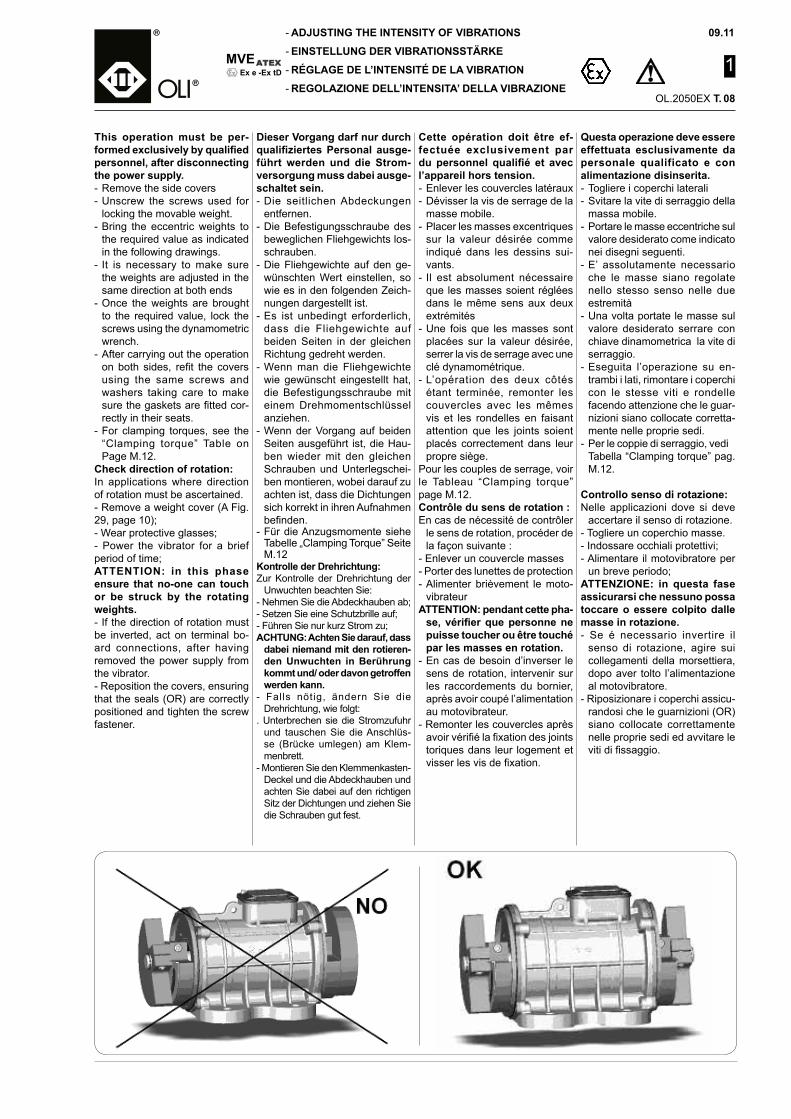
Check direction of rotation:In applications where direction of rotation must be ascertained.- Remove a weight cover (A Fig. 29, page 10);- Wear protective glasses;- Power the vibrator for a brief period of time;ATTENTION: in this phase ensure that no-one can touch or be struck by the rotating weights.- If the direction of rotation must be inverted, act on terminal bo-ard connections, after having removed the power supply from the vibrator.- Reposition the covers, ensuring that the seals (OR) are correctly positioned and tighten the screw fastener.
Dieser Vorgang darf nur durch qualifiziertes Personal ausge-führt werden und die Strom-versorgung muss dabei ausge-schaltet sein.- Die seitlichen Abdeckungen
entfernen.- Die Befestigungsschraube des
beweglichen Fliehgewichts los-schrauben.
- Die Fliehgewichte auf den ge-wünschten Wert einstellen, so wie es in den folgenden Zeich-nungen dargestellt ist.
- Es ist unbedingt erforderlich, dass die Fliehgewichte auf beiden Seiten in der gleichen Richtung gedreht werden.
- Wenn man die Fliehgewichte wie gewünscht eingestellt hat, die Befestigungsschraube mit einem Drehmomentschlüssel anziehen.
- Wenn der Vorgang auf beiden Seiten ausgeführt ist, die Hau-ben wieder mit den gleichen Schrauben und Unterlegschei-ben montieren, wobei darauf zu achten ist, dass die Dichtungen sich korrekt in ihren Aufnahmen befinden.
- Für die Anzugsmomente siehe Tabelle „Clamping Torque” Seite M.12
Kontrolle der Drehrichtung:Zur Kontrolle der Drehrichtung der
Unwuchten beachten Sie:- Nehmen Sie die Abdeckhauben ab;- Setzen Sie eine Schutzbrille auf;- Führen Sie nur kurz Strom zu;ACHTUNG: Achten Sie darauf, dass
dabei niemand mit den rotieren-den Unwuchten in Berührung kommt und/ oder davon getroffen werden kann.
- Falls nötig, ändern Sie die Drehrichtung, wie folgt:
. Unterbrechen sie die Stromzufuhr und tauschen Sie die Anschlüs-se (Brücke umlegen) am Klem-menbrett.
- Montieren Sie den Klemmenkasten-Deckel und die Abdeckhauben und achten Sie dabei auf den richtigen Sitz der Dichtungen und ziehen Sie die Schrauben gut fest.
Cette opération doit être ef-fectuée exclusivement par du personnel qualifié et avec l’appareil hors tension.- Enlever les couvercles latéraux- Dévisser la vis de serrage de la
masse mobile.- Placer les masses excentriques
sur la valeur désirée comme indiqué dans les dessins sui-vants.
- Il est absolument nécessaire que les masses soient réglées dans le même sens aux deux extrémités
- Une fois que les masses sont placées sur la valeur désirée, serrer la vis de serrage avec une clé dynamométrique.
- L’opération des deux côtés étant terminée, remonter les couvercles avec les mêmes vis et les rondelles en faisant attention que les joints soient placés correctement dans leur propre siège.
Pour les couples de serrage, voir le Tableau “Clamping torque” page M.12.Contrôle du sens de rotation :En cas de nécessité de contrôler
le sens de rotation, procéder de la façon suivante :
- Enlever un couvercle masses- Porter des lunettes de protection- Alimenter brièvement le moto-
vibrateurATTENTION: pendant cette pha-
se, vérifier que personne ne puisse toucher ou être touché par les masses en rotation.
- En cas de besoin d’inverser le sens de rotation, intervenir sur les raccordements du bornier, après avoir coupé l’alimentation au motovibrateur.
- Remonter les couvercles après avoir vérifié la fixation des joints toriques dans leur logement et visser les vis de fixation.
08
09.11
1
OL.2050EX T.
MVE
-
-
-
-Ex e -Ex tD
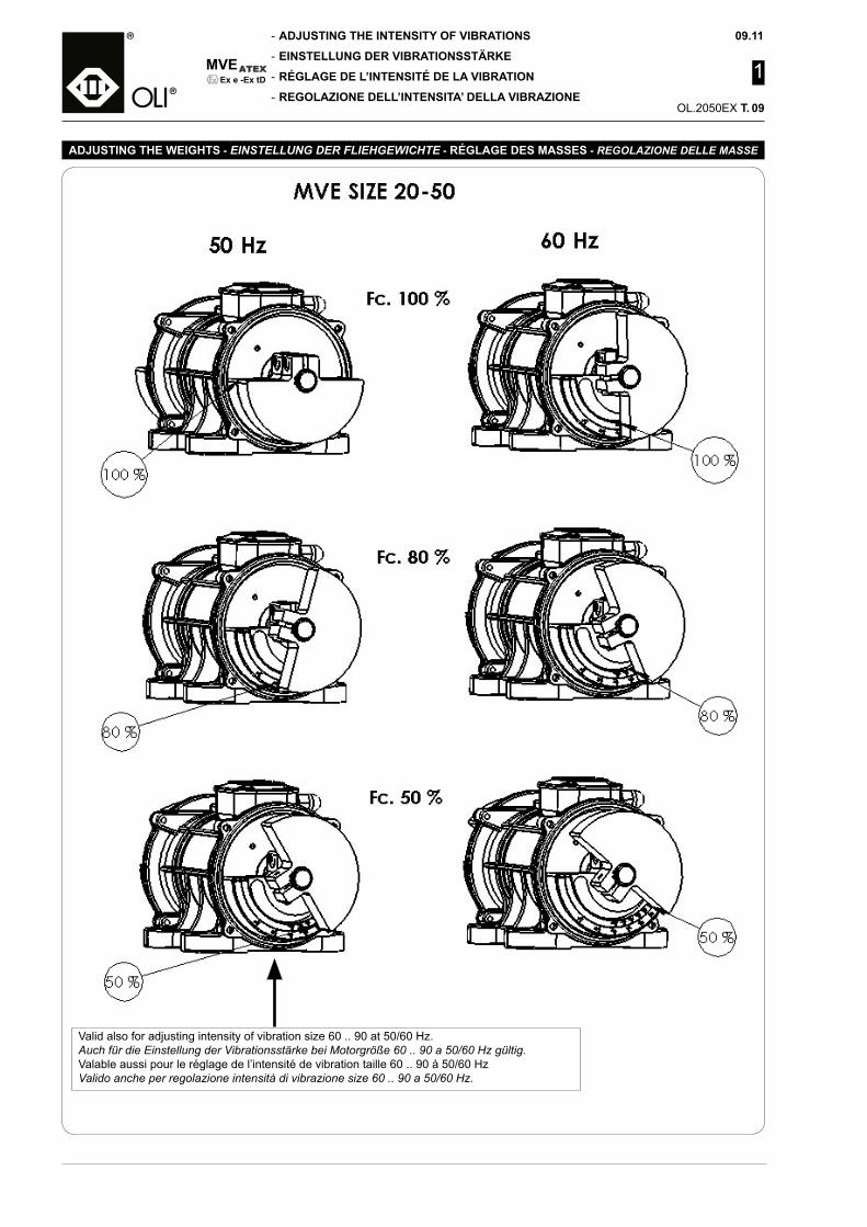
Valid also for adjusting intensity of vibration size 60 .. 90 at 50/60 Hz.Auch für die Einstellung der Vibrationsstärke bei Motorgröße 60 .. 90 a 50/60 Hz gültig.Valable aussi pour le réglage de l’intensité de vibration taille 60 .. 90 à 50/60 HzValido anche per regolazione intensità di vibrazione size 60 .. 90 a 50/60 Hz.
ADJUSTING THE WEIGHTS - EINSTELLUNG DER FLIEHGEWICHTE - RÉGLAGE DES MASSES - REGOLAZIONE DELLE MASSE
ADJUSTING THE INTENSITY OF VIBRATIONS
EINSTELLUNG DER VIBRATIONSSTÄRKE
RÉGLAGE DE L’INTENSITÉ DE LA VIBRATION
REGOLAZIONE DELL’INTENSITA’ DELLA VIBRAZIONE09

MVE
-
-
-
-
09.11
1
OL.2050EX T.
Ex e -Ex tD
ELEC
TRO
MEC
HA
NIC
AL
FEAT
UR
ES, O
VER
ALL
DIM
ENSI
ON
S, L
IFE
OF
BEA
RIN
GS
AN
D L
UB
RIC
ATIO
N
ELEK
TRO
MEC
HA
NIS
CH
E EI
GEN
SCH
AFT
EN, P
LATZ
BED
AR
F, S
TAN
DZE
IT D
ER L
AG
ER U
ND
SC
HM
IER
UN
GC
AR
AC
TÉR
ISTI
QU
ES É
LEC
TRO
MÉC
AN
IQU
ES, D
IMEN
SIO
NS
D’E
NC
OM
BR
EMEN
T, D
UR
ÉE D
ES R
OU
LEM
ENTS
ET
LUB
RIF
ICAT
ION
CA
RAT
TER
ISTI
CH
E EL
ETTR
OM
ECC
AN
ICH
E, D
IMEN
SIO
NI D
I IN
GO
MB
RO
, DU
RAT
A C
USC
INET
TI E
LU
BR
IFIC
AZI
ON
E
10
FEATURES
EIGENSCHAFTEN
CARACTÉRISTIQUES
CARATTERISTICHE
09.11
1
OL.2050EX T.
MVE
-
-
-
-Ex e -Ex tD
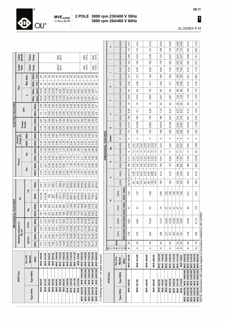
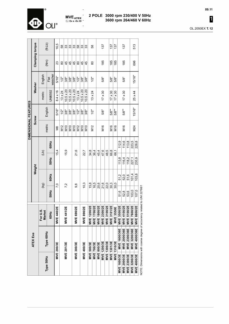
2 POLE 3000 rpm 230/400 V 50Hz 3600 rpm 264/460 V 60Hz
(*) W
orki
ng m
omen
t = 2
x st
atic
mom
ent
NO
TE: D
imen
sion
s w
ith c
oars
e de
gree
of a
ccur
ancy
rela
ted
to U
NI 2
2768
/1
ATEX
Exe
MEC
HAN
ICAL
FEA
TUR
ESEL
ECTR
IC F
EATU
RES
Wor
king
mom
ent (
*)kg
cm
FCPo
wer
Cur
rent
A m
ax (Y
)Po
wer
Fact
orla
/In
Exe
Cab
leTy
peC
able
glan
de
Kw
Hp
400V
460V
t EM
ax A
mb
Type
50H
zTy
pe 6
0Hz
For U
.S.
Mar
ket
kg*c
min
*Lb
kgLb
Cla
ssTe
mp.
Cla
ssTe
mp.
60H
z50
Hz
60H
z50
Hz
60H
z50
Hz
60H
z50
Hz
60H
z50
Hz
60H
z50
Hz
60H
z50
Hz
60H
z50
Hz
60H
z50
Hz
60H
z50
Hz
(sec
)60
Hz
(sec
)50
Hz
(°C)
60H
z(°C
)
MVE
200
/3E
MVE
440
/2E
3,72
2,61
3,23
2,27
187
189
412,
2641
6,7
0,18
0,21
0,24
0,28
0,35
0,35
0,78
0,87
3,3
3,30
18,0
018
,00
4040
4G2,
580
°CM
2080
°C
MVE
201
/3E
MVE
441
/2E
3,72
2,61
3,23
2,27
187
189
412,
2641
6,7
0,18
0,21
0,24
0,28
0,35
0,35
0,78
0,87
3,3
3,30
18,0
018
,00
4040
MVE
300
/3E
MVE
690
/2E
6,39
4,46
5,55
3,87
321
323
708
712,
10,
270,
280,
360,
380,
520,
450,
840,
893,
603,
5014
,00
14,0
040
40M
VE 4
00/3
EM
VE 8
90/2
E7,
965,
686,
914,
9340
741
189
790
6,1
0,30
0,36
0,40
0,48
0,58
0,60
0,88
0,88
3,50
3,50
15,0
015
,00
4040
MVE
500
/3E
MVE
120
0/2E
10,2
77,
388,
916,
4153
053
411
68,4
1177
,30,
500,
580,
670,
780,
960,
970,
840,
874,
004,
2012
,00
11,0
040
40M
VE 7
00/3
EM
VE 1
700/
2E14
,90
10,5
712
,93
9,18
758
765
1671
,116
86,5
0,66
0,75
0,89
1,01
1,25
1,24
0,83
0,88
4,30
5,00
11,0
08,
0040
40M
VE 8
00/3
EM
VE 1
800/
2E15
,68
11,0
613
,61
9,60
794
800
1750
,517
63,7
0,75
0,90
1,01
1,21
1,45
1,50
0,79
0,84
3,80
3,80
12,0
012
,00
4040
MVE
120
0/3E
MVE
230
0/2E
20,2
614
,00
17,5
912
,15
1005
1013
2215
,622
33,3
0,95
1,15
1,27
1,54
1,85
1,95
0,82
0,85
4,40
4,50
9,00
9,00
4040
MVE
130
0/3E
MVE
310
0/2E
27,5
818
,86
23,9
416
,37
1355
1365
2987
,230
09,3
1,30
1,38
1,74
1,85
2,44
2,25
0,82
0,87
5,20
5,00
7,50
8,00
4040
MVE
130
1/3E
MVE
310
1/2E
27,5
818
,86
23,9
416
,37
1355
1365
2987
,230
09,3
1,30
1,38
1,74
1,85
2,44
2,25
0,82
0,87
5,20
5,00
7,50
8,00
4040
MVE
131
0/3E
MVE
355
0E22
,34
22,3
419
,39
19,3
911
2316
1624
75,8
3562
,61,
301,
381,
741,
852,
442,
250,
820,
875,
205,
007,
508,
0040
40M
VE 1
600/
3EM
VE 1
600/
36E
MVE
350
0/2E
31,2
622
,22
27,1
419
,29
1601
1608
3529
,635
45,0
1,57
1,60
2,11
2,15
2,94
2,61
0,78
0,82
5,90
6,20
6,00
6,00
4040
4G4
110°
CM
2511
0°C
MVE
200
0/3E
MVE
200
0/36
EM
VE 4
100/
2E36
,78
27,6
031
,93
23,9
620
2719
9744
68,7
4402
,62,
002,
102,
682,
823,
753,
420,
740,
786,
506,
405,
505,
5040
40M
VE 2
300/
3EM
VE 2
300/
36E
MVE
510
0/2E
45,9
731
,87
39,9
027
,66
2302
2306
5075
,050
83,8
2,40
2,45
3,22
3,29
4,44
3,94
0,76
0,80
6,00
6,30
5,00
5,00
4040
MVE
320
0/3E
MVE
320
0/36
EM
VE 7
600/
2E68
,10
43,8
959
,11
38,1
032
5231
7671
69,4
7001
,82,
902,
903,
893,
895,
304,
610,
820,
858,
308,
205,
005,
0040
404G
611
0°C
M32
110°
CM
VE 4
000/
3EM
VE 4
000/
36E
MVE
880
0/2E
79,4
055
,99
68,9
248
,60
4033
4052
8891
,289
33,0
2,90
2,90
3,89
3,89
5,30
4,61
0,74
0,79
8,5
9,7
12,1
6,7
4040
ATEX
Exe
DIM
ENSI
ON
AL F
EATU
RES
D r a w i n g
Size
cm
ab
øgho
les
de
fh
il
n
Type
50H
zTy
pe 6
0Hz
For U
.S.
Mar
ket
(mm
)(in
ch)
(mm
)(in
ch)
(mm
)(in
ch)
(mm
)(in
ch)
(mm
)(in
ch)
n°(m
m)
(inch
)(m
m)
(inch
)(m
m)
(inch
)(m
m)
(inch
)(m
m)
(inch
)(m
m)
(inch
)(m
m)
(inch
)60
Hz
50H
z60
Hz
50H
z60
Hz
50H
z60
Hz
50H
z60
Hz
MVE
200
/3E
MVE
440
/2E
B20
219
8,62
411,
6162
-74
2.44
-2.9
110
64,
179
0,35
413
15,
157
159
6,26
150,
5964
2,52
121
4,76
123
4,84
112
4,41
MVE
201
/3E
MVE
441
/2E
A25
219
8,62
411,
6165
2,56
140
5,51
130,
514
162
6,37
815
56,
119
0,75
632,
4812
14,
7614
05,
5111
24,
4180
3,15
110
4,33
110,
4311
54,
5313
55,
3111
0,43
MVE
300
/3E
MVE
690
/2E
C30
260
10,2
443
1,69
803,
1511
04,
3311
0,43
415
46,
063
175
6,89
150,
5979
3,11
142
5,59
163
6,42
131
5,16
903,
5412
54,
9213
0,51
MVE
400
/3E
MVE
890
/2E
124
4,88
110
4,33
110,
4313
55,
3111
54,
5311
0,43
MVE
500
/3E
MVE
120
0/2E
D40
338
13,3
175
2,95
105
4,13
140
5,51
130,
514
168
6,61
419
67,
7222
0,87
923,
6216
96,
6517
87,
0115
86,
22M
VE 7
00/3
EM
VE 1
700/
2EM
VE 8
00/3
EM
VE 1
800/
2ED
50
311
12,2
447
1,85
120
4,72
170
6,69
170,
674
208
8,18
921
08,
2722
0,87
943,
718
07,
0920
58,
0717
06,
69M
VE 1
200/
3EM
VE 2
300/
2E31
112
,24
471,
85M
VE 1
300/
3EM
VE 3
100/
2E32
112
,64
471,
85M
VE 1
301/
3EM
VE 3
101/
2ED
5332
112
,64
471,
8510
03,
9418
07,
0917
0,67
423
69,
291
210
8,27
261,
0298
3,86
180
7,09
205
8,07
170
6,69
MVE
131
0/3E
MVE
355
0ED
5532
112
,64
471,
8510
03,
9420
07,
8717
0,67
423
69,
291
210
8,27
261,
0298
3,86
180
7,09
205
8,07
170
6,69
MVE
160
0/3E
MVE
160
0/36
EM
VE 3
500/
2ED
6041
816
,46
833,
2714
05,
5119
07,
4817
0,67
422
99,
016
247
9,72
301,
1812
04,
7224
79,
7222
08,
6622
28,
74M
VE 2
000/
3EM
VE 2
000/
36E
MVE
410
0/2E
MVE
230
0/3E
MVE
230
0/36
EM
VE 5
100/
2EM
VE 3
200/
3EM
VE 3
200/
36E
MVE
760
0/2E
D75
538
21,1
811
54,
5315
56,
1025
510
,04
250,
984
302
11,8
931
812
,535
1,38
147
5,79
295
11,6
273
10,7
264
10,4
MVE
400
0/3E
MVE
400
0/36
EM
VE 8
800/
2E
11
MVE
-
-
-
-
09.11
1
OL.2050EX T.
Ex e -Ex tD
NO
TE: D
imen
sion
s w
ith c
oars
e de
gree
of a
ccur
ancy
rela
ted
to U
NI 2
2768
/1
2 POLE 3000 rpm 230/400 V 50Hz 3600 rpm 264/460 V 60Hz
ATEX
Exe
DIM
ENSI
ON
AL F
EATU
RES
Wei
ght
Scre
wW
ashe
rC
lam
ping
torq
ue
Type
50H
zTy
pe 6
0Hz
For U
.S.
Mar
ket
(kg)
(Lb)
met
ricE
nglis
hm
etric
Eng
lish
(Nm
)(ft
-Lb)
60H
z50
Hz
60H
z50
Hz
60H
zU
NI6
592
Flat
was
cher
MVE
200
/3E
MVE
440
/2E
7,0
15,4
M8
5/16
"8.
4 x
165/
16"
2316
,5
MVE
201
/3E
MVE
441
/2E
7,2
15,9
M12
1/2"
13 x
24
1/2"
8058
M10
3/8"
10.5
x 2
03/
8"45
33M
103/
8"10
.5 x
20
3/8"
4533
MVE
300
/3E
MVE
690
/2E
9,8
21,6
M10
3/8"
10.5
x 2
03/
8"45
33M
121/
2"13
x 2
41/
2"80
58
MVE
400
/3E
MVE
890
/2E
10,3
22,7
M10
3/8"
10.5
x 2
03/
8"45
33M
103/
8"10
.5 x
20
3/8"
4533
MVE
500
/3E
MVE
120
0/2E
15,8
34,8
M12
1/2"
13 x
24
1/2"
8058
MVE
700
/3E
MVE
170
0/2E
16,5
36,4
MVE
800
/3E
MVE
180
0/2E
20,6
45,4
M16
5/8"
17 x
30
5/8"
185
137
MVE
120
0/3E
MVE
230
0/2E
21,6
47,6
MVE
130
0/3E
MVE
310
0/2E
22,0
48,5
MVE
130
1/3E
MVE
310
1/2E
30,3
66,8
M16
5/8"
"17
x 3
05/
8"18
513
7M
VE 1
310/
3EM
VE 3
550E
30,0
66,1
M16
5/8"
"17
x 3
05/
8"18
513
7M
VE 1
600/
3EM
VE 1
600/
36E
MVE
350
0/2E
51,6
51,2
113,
811
2,9
M16
5/8"
"17
x 3
05/
8"18
513
7M
VE 2
000/
3EM
VE 2
000/
36E
MVE
410
0/2E
52,8
52,0
116,
411
4,6
MVE
230
0/3E
MVE
230
0/36
EM
VE 5
100/
2E53
,651
,611
8,2
113,
8M
VE 3
200/
3EM
VE 3
200/
36E
MVE
760
0/2E
103,
010
1,4
227,
122
3,5
M24
15/1
6"25
x 4
415
/16"
696
513
MVE
400
0/3E
MVE
400
0/36
EM
VE 8
800/
2E10
7,0
103,
823
5,9
228,
8
12

09.11
1
OL.2050EX T.
MVE
-
-
-
-Ex e -Ex tD
ELEC
TRO
MEC
HA
NIC
AL
FEAT
UR
ES, O
VER
ALL
DIM
ENSI
ON
S, L
IFE
OF
BEA
RIN
GS
AN
D L
UB
RIC
ATIO
N
ELEK
TRO
MEC
HA
NIS
CH
E EI
GEN
SCH
AFT
EN, P
LATZ
BED
AR
F, S
TAN
DZE
IT D
ER L
AG
ER U
ND
SC
HM
IER
UN
GC
AR
AC
TÉR
ISTI
QU
ES É
LEC
TRO
MÉC
AN
IQU
ES, D
IMEN
SIO
NS
D’E
NC
OM
BR
EMEN
T, D
UR
ÉE D
ES R
OU
LEM
ENTS
ET
LUB
RIF
ICAT
ION
CA
RAT
TER
ISTI
CH
E EL
ETTR
OM
ECC
AN
ICH
E, D
IMEN
SIO
NI D
I IN
GO
MB
RO
, DU
RAT
A C
USC
INET
TI E
LU
BR
IFIC
AZI
ON
E13
FEATURES
EIGENSCHAFTEN
CARACTÉRISTIQUES
CARATTERISTICHE
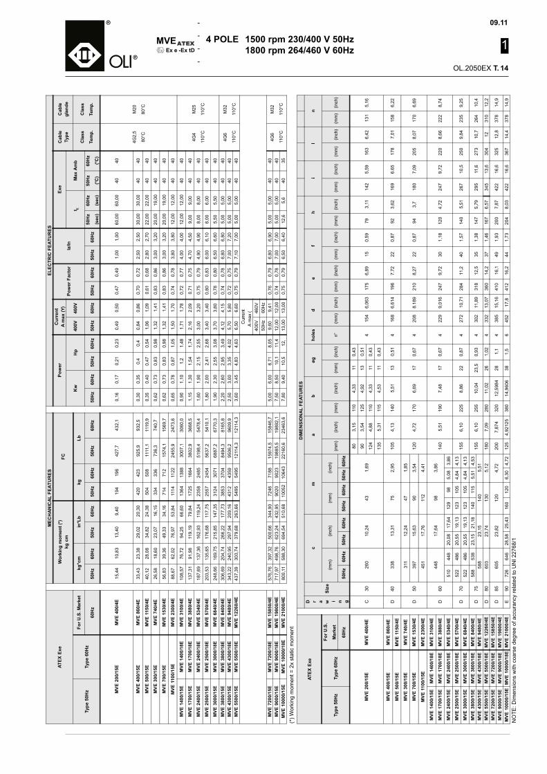
MVE
-
-
-
-
09.11
1
OL.2050EX T.
Ex e -Ex tD
4 POLE 1500 rpm 230/400 V 50Hz 1800 rpm 264/460 V 60Hz
ATEX
Exe
MEC
HAN
ICAL
FEA
TUR
ESEL
ECTR
IC F
EATU
RES
Wor
king
mom
ent (
*)kg
cm
FCPo
wer
Cur
rent
A m
ax (Y
)Po
wer
Fac
tor
la/In
Exe
Cab
leTy
peC
able
glan
de
Kw
Hp
400V
460V
t EM
ax A
mb
Type
50H
zTy
pe 6
0Hz
For U
.S. M
arke
tkg
*cm
in*L
bkg
LbC
lass
Tem
p.
Cla
ss
Tem
p.60
Hz
50H
z60
Hz
50H
z60
Hz
50H
z60
Hz
50H
z60
Hz
50H
z60
Hz
50H
z60
Hz
50H
z60
Hz
50H
z60
Hz
50H
z60
Hz
50H
z
(sec
)
60H
z
(sec
)
50H
z
(°C)
60H
z
(°C)
MVE
200
/15E
MVE
400
/4E
15,4
410
,83
13,4
09,
4019
419
642
7,7
432,
10,
160,
170,
210,
230,
490,
500,
470,
491,
001,
0060
,00
60,0
040
40
4G2,
5
80°C
M20
80°C
MVE
400
/15E
MVE
860
/4E
33,4
323
,38
29,0
220
,30
420
423
925,
993
2,5
0,30
0,35
0,4
0,4
0,84
0,86
0,70
0,72
2,50
2,50
30,0
030
,00
4040
MVE
500
/15E
MVE
115
0/4E
40,1
228
,08
34,8
224
,38
504
508
1111
,111
19,9
0,35
0,40
0,47
0,54
1,06
1,09
0,61
0,68
2,80
2,70
22,0
022
,00
4040
MVE
300
/15E
MVE
740
/4E
26,5
818
,60
23,0
716
,15
334
336
736,
374
0,7
0,62
0,73
0,83
0,98
1,32
1,41
0,83
0,86
3,00
3,20
20,0
019
,00
4040
MVE
700
/15E
MVE
153
0/4E
56,8
339
,36
49,3
334
,16
714
712
1574
,115
69,7
0,62
0,73
0,83
0,98
1,32
1,41
0,83
0,86
3,00
3,20
20,0
019
,00
4040
MVE
110
0/15
EM
VE 2
300/
4E88
,67
62,0
276
,97
53,8
411
1411
2224
55,9
2473
,60,
650,
780,
871,
051,
501,
700,
740,
783,
803,
8012
,00
12,0
040
40
MVE
140
0/15
EM
VE 1
400/
18E
MVE
310
0/4E
108,
5776
,72
94,2
566
,60
1364
1388
3007
,130
60,0
0,90
1,10
1,2
1,48
1,71
1,78
0,72
0,77
4,00
4,00
12,0
012
,00
4040
4G4
110°
C
M25
110°
C
MVE
170
0/15
EM
VE 1
700/
18E
MVE
388
0/4E
137,
3191
,98
119,
1979
,84
1725
1664
3802
,936
68,5
1,15
1,30
1,54
1,74
2,16
2,09
0,71
0,75
4,70
4,50
9,00
9,00
4040
MVE
240
0/15
EM
VE 2
400/
18E
MVE
534
0/4E
187,
6913
7,36
162,
9311
9,24
2358
2485
5198
,454
78,4
1,60
1,90
2,15
2,55
3,00
3,20
0,75
0,79
4,90
4,90
8,00
8,00
4040
MVE
250
0/15
EM
VE 2
500/
18E
MVE
570
0/4E
203,
5313
5,65
176,
6811
7,75
2557
2454
5637
,254
10,1
1,80
2,00
2,41
2,68
3,40
3,40
0,80
0,83
6,00
6,10
6,00
6,00
4040
MVE
300
0/15
EM
VE 3
000/
18E
MVE
684
0/4E
248,
6616
9,75
215,
8514
7,35
3124
3071
6887
,267
70,3
1,90
2,30
2,55
3,08
3,70
3,80
0,78
0,80
6,50
6,60
5,50
5,50
4040
MVE
380
0/15
EM
VE 3
800/
18E
MVE
840
0/4E
306,
6920
4,74
266,
2217
7,73
3853
3704
8494
,381
65,8
2,20
2,60
2,95
3,49
4,12
4,15
0,74
0,78
6,80
6,80
5,00
5,00
4040
4G6
110°
C
M32
110°
CM
VE 4
300/
15E
MVE
430
0/18
EM
VE 9
480/
4E34
3,22
240,
9529
7,94
209,
1643
1243
5995
06,2
9609
,92,
503,
003,
354,
025,
705,
800,
720,
757,
007,
205,
005,
0040
40M
VE 5
500/
15E
MVE
550
0/18
EM
VE 1
2260
/4E
437,
3930
3,74
379,
6826
3,66
5495
5495
1211
4,3
1211
4,3
3,60
3,45
4,83
4,63
6,50
6,60
0,75
0,79
7,10
7,00
5,00
5,00
4040
Cur
rent
A m
ax (
40
0V46
0V50
Hz
60H
zM
VE 7
200/
15E
MVE
720
0/18
EM
VE 1
5850
/4E
576,
7639
7,32
500,
6634
4,90
7246
7188
1597
4,5
1584
6,7
5,00
6,00
6,71
8,05
9,60
9,41
0,76
0,79
6,80
6,90
5,00
5,00
4040
4G6
110°
C
M32
110°
CM
VE 9
000/
15E
MVE
900
0/18
EM
VE 1
9800
/4E
717,
9749
8,76
623,
2443
2,95
9020
9023
1988
5,5
1989
2,1
7,50
8,50
10,1
11,4
12,0
012
,00
0,74
0,78
7,00
7,00
5,00
5,00
4040
MVE
100
00/1
5EM
VE 1
0000
/18E
MVE
210
00/4
E80
0,11
588,
3069
4,54
510,
6810
052
1064
322
160,
623
463,
67,
809,
4010
,512
,13
,00
13,0
00,
750,
796,
506,
4012
,65,
640
35
ATEX
Exe
DIM
ENSI
ON
AL F
EATU
RES
D r a w i n g
Size
cm
ab
øgho
les
de
fh
il
n
Type
50H
zTy
pe 6
0Hz
For U
.S.
Mar
ket
(mm
)(in
ch)
(mm
)(in
ch)
(mm
)(in
ch)
(mm
)(in
ch)
(mm
)(in
ch)
n°(m
m)
(inch
)(m
m)
(inch
)(m
m)
(inch
)(m
m)
(inch
)(m
m)
(inch
)(m
m)
(inch
)(m
m)
(inch
)
60H
z50
Hz
60H
z50
Hz
60H
z50
Hz
60H
z50
Hz
60H
z
MVE
200
/15E
MVE
400
/4E
C30
260
10,2
443
1,69
803,
1511
04,
3311
0,43
415
46,
063
175
6,89
150,
5979
3,11
142
5,59
163
6,42
131
5,16
903,
5412
54,
9213
0,51
124
4,88
110
4,33
110,
43
135
5,31
115
4,53
110,
43
MVE
400
/15E
MVE
860
/4E
D40
338
13,3
175
2,95
105
4,13
140
5,51
130,
514
168
6,61
419
67.
7222
0,87
923,
6216
96.
6517
87,
0115
86,
22M
VE 5
00/1
5EM
VE 1
150/
4E
MVE
300
/15E
MVE
740
/4E
D50
311
12,2
447
1,85
120
4,72
170
6,69
170,
674
208
8.18
921
08,
2722
0,87
943,
718
07,
0920
58,
0717
06,
69M
VE 7
00/1
5EM
VE 1
530/
4E39
715
,63
903,
54
MVE
110
0/15
EM
VE 2
300/
4E45
117
,76
112
4,41
MVE
140
0/15
EM
VE 1
400/
18E
MVE
310
0/4E
D60
448
17,6
498
3,86
140
5,51
190
7,48
170,
674
229
9,01
624
79,
7230
1,18
120
4,72
247
9,72
220
8,66
222
8,74
MVE
170
0/15
EM
VE 1
700/
18E
MVE
388
0/4E
MVE
240
0/15
EM
VE 2
400/
18E
MVE
534
0/4E
510
448
20,0
817
,64
129
985,
083,
86
MVE
250
0/15
EM
VE 2
500/
18E
MVE
570
0/4E
D70
522
486
20,5
519
,13
123
105
4,84
4,13
155
6,10
225
8,86
220,
874
272
10,7
128
411
,240
1,57
140
5,51
267
10,5
250
9,84
235
9,25
MVE
300
0/15
EM
VE 3
000/
18E
MVE
684
0/4E
522
486
20,5
519
,13
123
105
4,84
4,13
MVE
380
0/15
EM
VE 3
800/
18E
MVE
840
0/4E
D75
588
538
23,1
521
,18
140
115
5,51
4,53
155
6,10
255
10,0
423
,50,
934
302
11,8
931
812
,535
1,38
147
5,79
295
11,6
273
10,7
264
10,4
MVE
430
0/15
EM
VE 4
300/
18E
MVE
948
0/4E
588
23,1
514
05,
51M
VE 5
500/
15E
MVE
550
0/18
EM
VE 1
2260
/4E
D80
603
23,7
413
05,
1218
07,
0928
011
,02
261,
024
332
13,0
736
014
,237
1,46
167
6,57
345
13,6
304
1231
012
,2M
VE 7
200/
15E
MVE
720
0/18
EM
VE 1
5850
/4E
D85
605
23,8
212
04,
7220
07,
874
320
12,5
984
281,
14
385
15,1
641
016
,149
1,93
200
7,87
422
16,6
325
12,8
378
14,9
MVE
900
0/15
EM
VE 9
000/
18E
MVE
198
00/4
EM
VE 1
0000
/15E
MVE
100
00/1
8EM
VE 2
1000
/4E
E90
726
646
28,5
825
,43
160
120
6,30
4,72
125
4,92
125
380
14,9
606
381,
56
452
17,8
412
16,2
441,
7320
48,
0342
216
,636
714
,437
814
,9
(*) W
orki
ng m
omen
t = 2
x st
atic
mom
ent
NO
TE: D
imen
sion
s w
ith c
oars
e de
gree
of a
ccur
ancy
rela
ted
to U
NI 2
2768
/1
14
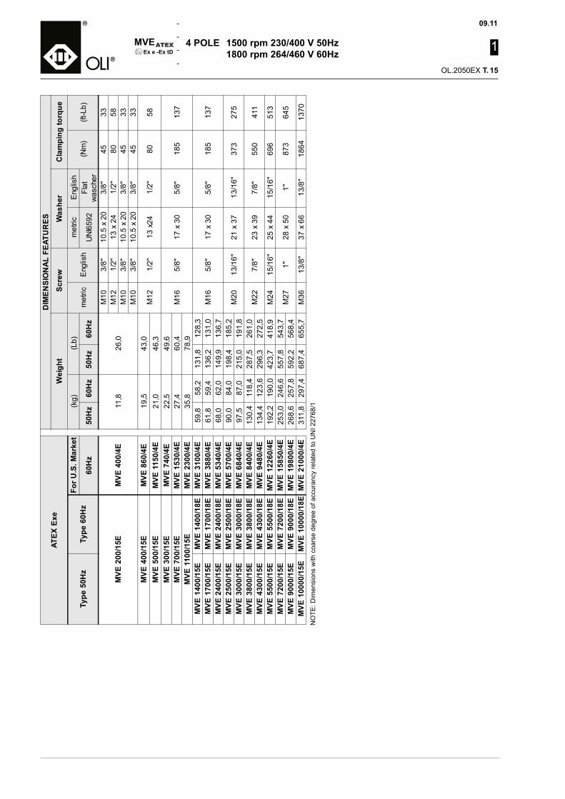
09.11
1
OL.2050EX T.
MVE
-
-
-
-Ex e -Ex tD
NO
TE: D
imen
sion
s w
ith c
oars
e de
gree
of a
ccur
ancy
rela
ted
to U
NI 2
2768
/1
4 POLE 1500 rpm 230/400 V 50Hz 1800 rpm 264/460 V 60Hz
ATEX
Exe
DIM
ENSI
ON
AL F
EATU
RES
Wei
ght
Scre
wW
ashe
rC
lam
ping
torq
ue
Type
50H
zTy
pe 6
0Hz
For U
.S. M
arke
t(k
g)(L
b)m
etric
Eng
lish
met
ricE
nglis
h(N
m)
(ft-L
b)60
Hz
50H
z60
Hz
50H
z60
Hz
UN
I659
2Fl
atw
asch
er
MVE
200
/15E
MVE
400
/4E
11,8
26,0
M10
3/8"
10.5
x 2
03/
8"45
33M
121/
2"13
x 2
41/
2"80
58M
103/
8"10
.5 x
20
3/8"
4533
M10
3/8"
10.5
x 2
03/
8"45
33M
VE 4
00/1
5EM
VE 8
60/4
E19
,543
,0M
121/
2"13
x24
1/2"
8058
MVE
500
/15E
MVE
115
0/4E
21,0
46,3
MVE
300
/15E
MVE
740
/4E
22,5
49,6
M16
5/8"
17 x
30
5/8"
185
137
MVE
700
/15E
MVE
153
0/4E
27,4
60,4
MVE
110
0/15
EM
VE 2
300/
4E35
,878
,9M
VE 1
400/
15E
MVE
140
0/18
EM
VE 3
100/
4E59
,858
,213
1,8
128,
3M
165/
8"17
x 3
05/
8"18
513
7M
VE 1
700/
15E
MVE
170
0/18
EM
VE 3
880/
4E61
,859
,413
6,2
131,
0M
VE 2
400/
15E
MVE
240
0/18
EM
VE 5
340/
4E68
,062
,014
9,9
136,
7M
VE 2
500/
15E
MVE
250
0/18
EM
VE 5
700/
4E90
,084
,019
8,4
185,
2M
2013
/16"
21 x
37
13/1
6"37
327
5M
VE 3
000/
15E
MVE
300
0/18
EM
VE 6
840/
4E97
,587
,021
5,0
191,
8M
VE 3
800/
15E
MVE
380
0/18
EM
VE 8
400/
4E13
0,4
118,
428
7,5
261,
0M
227/
8"23
x 3
97/
8"55
041
1M
VE 4
300/
15E
MVE
430
0/18
EM
VE 9
480/
4E13
4,4
123,
629
6,3
272,
5M
VE 5
500/
15E
MVE
550
0/18
EM
VE 1
2260
/4E
192,
219
0,0
423,
741
8,9
M24
15/1
6"25
x 4
415
/16"
696
513
MVE
720
0/15
EM
VE 7
200/
18E
MVE
158
50/4
E25
3,0
246,
655
7,8
543,
7M
271"
28 x
50
1"87
364
5M
VE 9
000/
15E
MVE
900
0/18
EM
VE 1
9800
/4E
268,
625
7,8
592,
256
8,4
MVE
100
00/1
5EM
VE 1
0000
/18E
MVE
210
00/4
E31
1,8
297,
468
7,4
655,
7M
3613
/8"
37 x
66
13/8
"18
6413
70
15
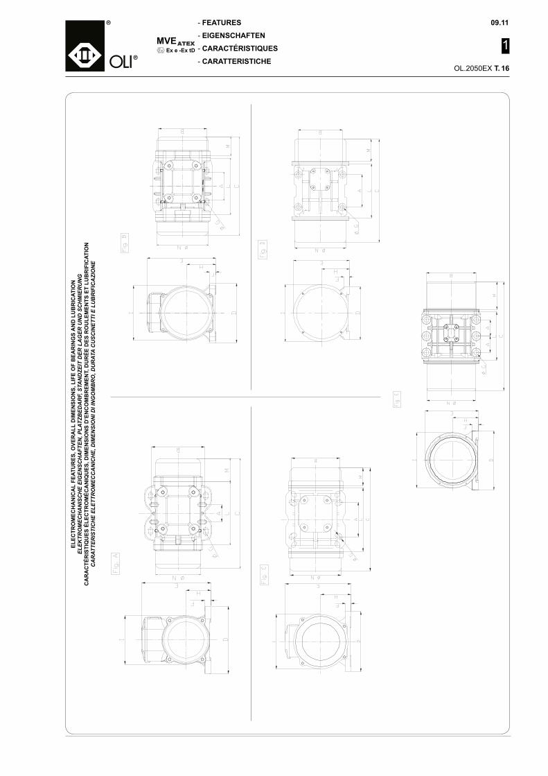
MVE
-
-
-
-
09.11
1
OL.2050EX T.
Ex e -Ex tD
ELEC
TRO
MEC
HA
NIC
AL
FEAT
UR
ES, O
VER
ALL
DIM
ENSI
ON
S, L
IFE
OF
BEA
RIN
GS
AN
D L
UB
RIC
ATIO
N
ELEK
TRO
MEC
HA
NIS
CH
E EI
GEN
SCH
AFT
EN, P
LATZ
BED
AR
F, S
TAN
DZE
IT D
ER L
AG
ER U
ND
SC
HM
IER
UN
GC
AR
AC
TÉR
ISTI
QU
ES É
LEC
TRO
MÉC
AN
IQU
ES, D
IMEN
SIO
NS
D’E
NC
OM
BR
EMEN
T, D
UR
ÉE D
ES R
OU
LEM
ENTS
ET
LUB
RIF
ICAT
ION
CA
RAT
TER
ISTI
CH
E EL
ETTR
OM
ECC
AN
ICH
E, D
IMEN
SIO
NI D
I IN
GO
MB
RO
, DU
RAT
A C
USC
INET
TI E
LU
BR
IFIC
AZI
ON
E
16
FEATURES
EIGENSCHAFTEN
CARACTÉRISTIQUES
CARATTERISTICHE

09.11
1
OL.2050EX T.
MVE
-
-
-
-Ex e -Ex tD
6 POLE 1000 rpm 230/400 V 50Hz 1200 rpm 264/460 V 60Hz
ATEX
Exe
MEC
HAN
ICAL
FEA
TUR
ESEL
ECTR
IC F
EATU
RES
Wor
king
mom
ent (
*)kg
cm
FCPo
wer
Cur
rent
A m
ax (Y
)Po
wer
Fac
tor
la/In
Exe
Cab
leTy
peC
able
glan
de
Kw
Hp
400V
460V
t EM
ax A
mb
Type
50H
zTy
pe 6
0Hz
For U
.S. M
arke
tkg
*cm
in*L
bkg
LbC
lass
Tem
p.
Cla
ss
Tem
p.60
Hz
50H
z60
Hz
50H
z60
Hz
50H
z60
Hz
50H
z60
Hz
50H
z60
Hz
50H
z60
Hz
50H
z60
Hz
50H
z60
Hz
50H
z60
Hz
50H
z
(sec
)
60H
z
(sec
)
50H
z
(°C)
60H
z
(°C)
MVE
50/
1EM
VE 9
0/6E
9,49
6,59
8,24
5,72
5353
116,
811
6,8
0,12
0,14
0,16
0,19
0,40
0,40
0.32
0.38
1,00
1,00
60,0
060
,00
4040
4G1,
5
80°C
M16
80°C
MVE
100
/1E
MVE
200
/6E
18,8
013
,18
16,3
211
,44
105
106
231,
523
3,7
0,12
0,14
0,16
0,19
0,40
0,40
0.32
0.38
1,00
1,00
60,0
060
,00
4040
MVE
200/
1EM
VE 4
10/6
E33
,49
23,3
829
,07
20,3
018
718
841
2,3
414,
50,
180,
210,
240,
280,
530,
510,
370.
421,
001,
0060
,00
60,0
040
40
MVE
300
/1E
MVE
680
/6E
47,8
233
,46
41,5
129
,04
267
269
588,
659
30,
350,
380,
470,
510,
670,
640,
680,
722,
502,
5030
,00
30,0
040
40
MVE
500
/1E
MVE
110
0/6E
85,0
759
,57
73,8
551
,71
475
479
1047
1056
0,35
0,40
0,47
0,54
1,20
1,15
0,60
0,64
2,80
2,70
24,0
024
,00
4040
MVE
800
/1E
MVE
800
/12E
MVE
173
0/6E
137,
3710
8,58
119,
2494
,25
767
873
1691
1925
0,68
0,76
0,91
1,02
1,29
1,26
0,66
0,70
2,80
2,80
24,0
024
,00
4040
4G4
110°
C
M25
110°
C
MVE
110
0/1E
MVE
110
0/12
EM
VE 2
350/
6E18
7,69
137,
3116
2,93
119,
1910
4811
0423
1024
340,
750,
801,
011,
071,
421,
320,
590,
643,
203,
1019
,00
19,0
040
40
MVE
150
0/1E
MVE
150
0/12
EM
VE 3
090/
6E28
4,76
196,
5124
7,19
170,
5815
9015
8035
0534
831,
101,
301,
481,
742,
102,
000,
660,
703,
303,
3016
,00
16,0
040
40
MVE
160
0/1E
MVE
160
0/12
EM
VE 3
580/
6E29
9,63
203,
4726
0,09
176,
6216
7316
3636
8836
071,
101,
301,
481,
742,
833,
220,
630,
683,
703,
6013
,00
13,0
040
40
MVE
210
0/1E
MVE
210
0/12
EM
VE 4
740/
6E37
3,05
248,
7432
3,83
215,
9220
8320
0045
9244
091,
501,
802,
012,
413,
003,
000,
700,
724,
304,
4010
,00
10,0
040
40
MVE
260
0/1E
MVE
260
0/12
EM
VE 5
690/
6E46
7,44
306,
7040
5,76
266,
2326
1024
6657
5454
371,
962,
102,
632,
823,
633,
380,
680,
704,
804,
809,
009,
0040
40
4G6
110°
C
M32
110°
C
MVE
300
0/1E
MVE
300
0/12
EM
VE 6
620/
6E54
0,33
379,
7146
9,03
329,
6130
1730
5366
5167
312,
202,
402,
953,
224,
504,
300,
720,
755,
005,
008,
008,
0040
40M
VE 3
800/
1EM
VE 3
800/
12E
MVE
845
0/6E
680,
3843
7,41
590,
6137
9,70
3799
3517
8375
7754
2,50
3,00
3,35
4,02
4,67
4,88
0,71
0,75
5,90
6,00
6,00
6,00
4040
MVE
470
0/1E
MVE
470
0/12
EM
VE 1
0370
/6E
838,
3458
4,17
727,
7350
7,09
4681
4697
1032
010
355
3,20
3,90
4,29
5,23
6,50
6,00
0,64
0,69
5,50
5,70
7,00
7,00
4040
MVE
520
0/1E
MVE
520
0/12
EM
VE 1
1500
/6E
929,
8665
4,57
807,
1756
8,20
5192
5263
1144
611
603
3,80
4,00
5,10
5,36
6,92
6,36
0,69
0,74
5,50
5,50
7,00
7,00
4040
MVE
650
0/1E
MVE
650
0/12
EM
VE 1
4360
/6E
1165
,19
823,
9610
11,4
571
5,24
6506
6625
1434
314
605
4,30
5,00
5,77
6,71
7,76
7,81
0,68
0,72
6,20
6,00
6,00
6,00
4040
Cur
rent
A m
ax (
40
0V46
0V50
Hz
60H
zM
VE 8
000/
1EM
VE 8
000/
12E
MVE
177
50/6
E14
35,9
892
9,80
1246
,51
807,
1280
1874
7617
676
1648
27,
107,
509,
5210
,06
12,6
011
,60
0,67
0,72
6,00
6,20
6,00
6,00
4040
4G6
110°
C
M32
110°
C
MVE
900
0/1E
MVE
900
0/12
EM
VE 1
9120
/6E
1600
,39
1165
,23
1389
,23
1011
,49
8936
9369
1970
020
655
7,50
8,30
10,0
611
,13
13,2
012
,60
0,73
0,76
6,30
6,20
5,50
5,50
4040
MVE
100
00/1
EM
VE 1
0000
/12E
MVE
214
00/6
E17
88,4
412
39,9
815
52,4
610
76,3
799
8699
7022
015
2198
07,
608,
0010
,19
10,7
313
,50
12,7
00,
640,
666,
406,
405,
505,
5040
40M
VE 1
3000
/1E
//
2329
,84
1647
,42
2022
,43
1430
,05
1300
913
246
2868
029
202
10,0
010
,00
13,4
113
,41
17,0
016
,00
0,72
6,20
5,50
/35
/
ATEX
Exe
DIM
ENSI
ON
AL F
EATU
RES
D r a w i n g
Size
cm
ab
øgho
les
de
fh
il
n
Type
50H
zTy
pe 6
0Hz
For U
.S.
Mar
ket
(mm
)(in
ch)
(mm
)(in
ch)
(mm
)(in
ch)
(mm
)(in
ch)
(mm
)(in
ch)
n°(m
m)
(inch
)(m
m)
(inch
)(m
m)
(inch
)(m
m)
(inch
)(m
m)
(inch
)(m
m)
(inch
)(m
m)
(inch
)
60H
z50
Hz
60H
z50
Hz
60H
z50
Hz
60H
z50
Hz
60H
z
MVE
50/
1EM
VE 9
0/6E
C30
260
10,2
443
1,69
803,
1511
04,
3311
0,43
415
46,
0617
56,
8915
0,59
793,
1114
25,
5916
36,
4213
15,
1690
3,54
125
4,92
130,
51
MVE
100
/1E
MVE
200
/6E
300
11,8
163
2,48
124
4,88
110
4,33
110,
43
135
5,31
115
4,53
110,
43
MVE
200/
1EM
VE 4
10/6
ED
4033
813
,31
752,
9510
54,
1314
05,
5113
0,51
416
86,
6119
67,
7222
0,87
923,
6216
96,
6517
87,
0115
86,
22
MVE
300
/1E
MVE
680
/6E
D50
397
16,6
390
3,54
120
4,72
170
6,69
170,
674
208
8,19
210
8,27
220,
8794
3,70
180
7,09
205
8,07
170
6,69
MVE
500
/1E
MVE
110
0/6E
441
17,3
611
24,
41
MVE
800
/1E
MVE
800
/12E
MVE
173
0/6E
D60
448
17,6
498
3,86
140
5,51
190
7,48
170,
674
229
9,02
247
9,72
301,
1812
04,
7224
79,
7222
08,
6622
28,
74M
VE 1
100/
1EM
VE 1
100/
12E
MVE
235
0/6E
510
448
20,0
817
,64
129
985,
083,
86
MVE
150
0/1E
MVE
150
0/12
EM
VE 3
090/
6E56
251
022
,13
20,0
815
412
96,
065,
08
MVE
160
0/1E
MVE
160
0/12
EM
VE 3
580/
6ED
7055
652
221
,89
20,5
514
012
35,
514,
8415
56,
122
58,
8622
0,87
427
210
,71
284
11,1
840
1,57
140
5,51
267
10,5
125
09,
8423
59,
25M
VE 2
100/
1EM
VE 2
100/
12E
MVE
474
0/6E
616
522
24,2
520
,55
170
123
6,69
4,84
MVE
260
0/1E
MVE
260
0/12
EM
VE 5
690/
6ED
7570
858
827
,87
23,1
520
014
07,
875,
5115
56,
125
510
,04
23,5
0,93
430
211
,89
318
12,5
235
1,38
147
5,79
295
11,6
127
310
,75
264
10,3
9M
VE 3
000/
1EM
VE 3
000/
12E
MVE
662
0/6E
608
23,9
415
05,
91M
VE 3
800/
1EM
VE 3
800/
12E
MVE
845
0/6E
D80
683
603
26,8
923
,74
170
130
6,69
5,12
180
7,09
280
11,0
226
1,02
433
213
,07
360
14,1
737
1,46
167
6,57
345
13,5
830
411
,97
310
12,2
0M
VE 4
700/
1EM
VE 4
700/
12E
MVE
103
70/6
E73
368
328
,86
26,8
919
517
07,
686,
69M
VE 5
200/
1EM
VE 5
200/
12E
MVE
115
00/6
ED
8568
560
526
,97
23,8
216
012
06,
304,
7220
07,
8732
012
,60
261,
104
385
15,1
641
016
,14
491,
9320
07,
8742
216
,61
325
12,8
037
814
,88
MVE
650
0/1E
MVE
650
0/12
EM
VE 1
4360
/6E
685
26,9
716
06,
30M
VE 8
000/
1EM
VE 8
000/
12E
MVE
177
50/6
ED
8578
568
530
,91
26,9
721
016
08,
276,
3020
07,
8732
012
,60
261,
14
385
15,1
641
016
,149
1,93
200
7,87
422
16,6
132
512
,80
378
14,9
MVE
900
0/1E
MVE
900
0/12
EM
VE 1
9120
/6E
785
685
30,9
126
,97
210
160
8,27
6,30
MVE
100
00/1
EM
VE 1
0000
/12E
MVE
214
00/6
EE
9082
632
,52
210
8,27
125
4,92
380
14,9
638
1,5
645
217
,841
216
,244
1,73
204
8,03
422
16,6
367
14,4
378
14,9
MVE
130
00/1
E/
/92
682
636
,46
32,5
226
021
010
,24
8,27
17
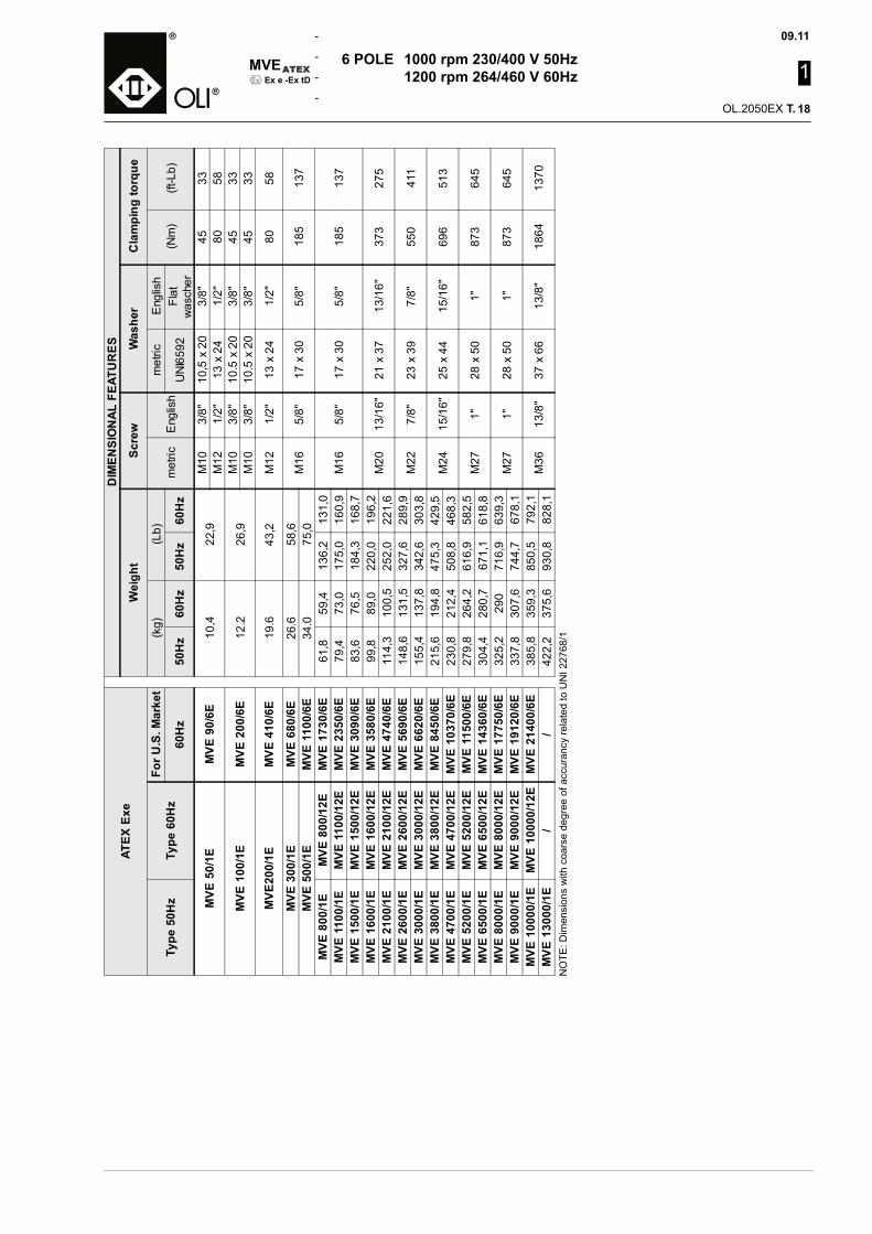
MVE
-
-
-
-
09.11
1
OL.2050EX T.
Ex e -Ex tD
6 POLE 1000 rpm 230/400 V 50Hz 1200 rpm 264/460 V 60Hz
ATEX
Exe
DIM
ENSI
ON
AL F
EATU
RES
Wei
ght
Scre
wW
ashe
rC
lam
ping
torq
ue
Type
50H
zTy
pe 6
0Hz
For U
.S. M
arke
t(k
g)(L
b)m
etric
Eng
lish
met
ricE
nglis
h(N
m)
(ft-L
b)60
Hz
50H
z60
Hz
50H
z60
Hz
UN
I659
2Fl
atw
asch
er
MVE
50/
1EM
VE 9
0/6E
10,4
22,9
M10
3/8"
10,5
x 2
03/
8"45
33M
121/
2"13
x 2
41/
2"80
58
MVE
100
/1E
MVE
200
/6E
12.2
26,9
M10
3/8"
10.5
x 2
03/
8"45
33M
103/
8"10
.5 x
20
3/8"
4533
MVE
200/
1EM
VE 4
10/6
E19
.643
,2M
121/
2"13
x 2
41/
2"80
58
MVE
300
/1E
MVE
680
/6E
26.6
58,6
M16
5/8"
17 x
30
5/8"
185
137
MVE
500
/1E
MVE
110
0/6E
34.0
75,0
MVE
800
/1E
MVE
800
/12E
MVE
173
0/6E
61,8
59,4
136,
213
1,0
M16
5/8"
17 x
30
5/8"
185
137
MVE
110
0/1E
MVE
110
0/12
EM
VE 2
350/
6E79
,473
,017
5,0
160,
9M
VE 1
500/
1EM
VE 1
500/
12E
MVE
309
0/6E
83,6
76,5
184,
316
8,7
MVE
160
0/1E
MVE
160
0/12
EM
VE 3
580/
6E99
,889
,022
0,0
196,
2M
2013
/16"
21 x
37
13/1
6"37
327
5M
VE 2
100/
1EM
VE 2
100/
12E
MVE
474
0/6E
114,
310
0,5
252,
022
1,6
MVE
260
0/1E
MVE
260
0/12
EM
VE 5
690/
6E14
8,6
131,
532
7,6
289,
9M
227/
8"23
x 3
97/
8"55
041
1M
VE 3
000/
1EM
VE 3
000/
12E
MVE
662
0/6E
155,
413
7,8
342,
630
3,8
MVE
380
0/1E
MVE
380
0/12
EM
VE 8
450/
6E21
5,6
194,
847
5,3
429,
5M
2415
/16"
25 x
44
15/1
6"69
651
3M
VE 4
700/
1EM
VE 4
700/
12E
MVE
103
70/6
E23
0,8
212,
450
8,8
468,
3M
VE 5
200/
1EM
VE 5
200/
12E
MVE
115
00/6
E27
9,8
264,
261
6,9
582,
5M
271"
28 x
50
1"87
364
5M
VE 6
500/
1EM
VE 6
500/
12E
MVE
143
60/6
E30
4,4
280,
767
1,1
618,
8M
VE 8
000/
1EM
VE 8
000/
12E
MVE
177
50/6
E32
5,2
290
716,
963
9,3
M27
1"28
x 5
01"
873
645
MVE
900
0/1E
MVE
900
0/12
EM
VE 1
9120
/6E
337,
830
7,6
744,
767
8,1
MVE
100
00/1
EM
VE 1
0000
/12E
MVE
214
00/6
E38
5,8
359,
385
0,5
792,
1M
3613
/8"
37 x
66
13/8
"18
6413
70M
VE 1
3000
/1E
//
422,
237
5,6
930,
882
8,1
NO
TE: D
imen
sion
s w
ith c
oars
e de
gree
of a
ccur
ancy
rela
ted
to U
NI 2
2768
/1
18
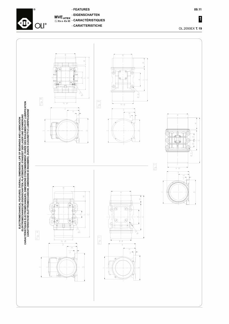
09.11
1
OL.2050EX T.
MVE
-
-
-
-Ex e -Ex tD
ELEC
TRO
MEC
HA
NIC
AL
FEAT
UR
ES, O
VER
ALL
DIM
ENSI
ON
S, L
IFE
OF
BEA
RIN
GS
AN
D L
UB
RIC
ATIO
N
ELEK
TRO
MEC
HA
NIS
CH
E EI
GEN
SCH
AFT
EN, P
LATZ
BED
AR
F, S
TAN
DZE
IT D
ER L
AG
ER U
ND
SC
HM
IER
UN
GC
AR
AC
TÉR
ISTI
QU
ES É
LEC
TRO
MÉC
AN
IQU
ES, D
IMEN
SIO
NS
D’E
NC
OM
BR
EMEN
T, D
UR
ÉE D
ES R
OU
LEM
ENTS
ET
LUB
RIF
ICAT
ION
CA
RAT
TER
ISTI
CH
E EL
ETTR
OM
ECC
AN
ICH
E, D
IMEN
SIO
NI D
I IN
GO
MB
RO
, DU
RAT
A C
USC
INET
TI E
LU
BR
IFIC
AZI
ON
E19
FEATURES
EIGENSCHAFTEN
CARACTÉRISTIQUES
CARATTERISTICHE

MVE
-
-
-
-
09.11
1
OL.2050EX T.
Ex e -Ex tD
8 POLE 750 rpm 230/400 V 50Hz 900 rpm 264/460 V 60Hz
(*) W
orki
ng m
omen
t = 2
x st
atic
mom
ent
ATE
X E
xe
ME
CH
ANIC
AL F
EAT
UR
ES
ELE
CTR
IC F
EAT
UR
ES
Wor
king
mom
ent (
*)kg
cm
FCP
ower
Cur
rent
A m
ax (Y
)P
ower
Fact
orla
/In
Exe
Cab
leTy
peC
able
glan
de
Kw
Hp
400V
460V
t EM
ax A
mb
Type
50-
60H
z
For U
.S.
Mar
ket
kg*c
min
*Lb
kgLb
Cla
ssTe
mp.
Cla
ssTe
mp.
60H
z50
-60H
z50
-60H
z50
Hz
60H
z50
Hz
60H
z50
Hz
60H
z50
Hz
60H
z50
Hz
60H
z50
Hz
60H
z50
Hz
60H
z50
Hz
(sec
)60
Hz
(sec
)50
Hz
(°C
)60
Hz
(°C
)M
VE 1
50/0
75E
MVE
330
/8E
33,3
928
,98
105
151
231
333
0,2
3 0
,25
0,3
1 0
,34
1,14
1,14
0,29
0,37
1,50
1,50
30,0
030
,00
4040
4G1,
580
°CM
1680
°CM
VE 2
50/0
75E
MVE
550
/8E
57,2
749
,71
180
259
397
571
0,3
5 0
,38
0,4
7 0
,51
1,15
1,15
0,41
0,45
1,70
1,70
30,0
030
,00
4040
MVE
400
/075
EM
VE 8
80/8
E84
,02
72,9
326
438
058
283
8 0
,35
0,3
8 0
,47
0,5
11,
151,
150,
410,
451,
901,
9030
,00
30,0
040
40M
VE 6
50/0
75E
MVE
143
0/8E
137,
3111
9,19
431
621
950
1369
0,5
0 0
,60
0,6
7 0
,80
1,20
1,20
0,56
0,62
2,20
2,20
30,0
030
,00
4040
4G4
110°
CM
2511
0°C
MVE
900
/075
EM
VE 2
000/
8E18
7,72
162,
9558
984
912
9918
72 0
,65
0,7
8 0
,87
1,0
51,
231,
290,
570,
622,
502,
5025
,00
25,0
040
40M
VE 1
300/
075E
MVE
290
0/8E
299,
6026
0,07
941
1355
2075
2987
1,0
0 1
,10
1,3
4 1
,48
1,86
1,83
0,69
0,72
3,00
3,00
20,0
020
,00
4040
MVE
210
0/07
5EM
VE 4
620/
8E46
7,41
405,
7414
6821
1432
3646
61 1
,50
1,8
0 2
,01
2,4
12,
812,
890,
640,
654,
204,
1012
,00
12,0
040
40
4G6
110°
CM
3211
0°C
MVE
310
0/07
5EM
VE 6
820/
8E68
0,34
590,
5721
3730
7747
1167
84 2
,00
2,3
0 2
,68
3,0
83,
793,
770,
680,
734,
004,
0012
,00
12,0
040
40M
VE 3
800/
075E
MVE
836
0/8E
838,
4372
7,80
2633
3792
5805
8360
2,5
0 3
,00
3,3
5 4
,02
6,00
6,00
0,66
0,67
3,90
4,00
12,0
012
,00
4040
MVE
420
0/07
5EM
VE 9
240/
8E92
9,74
807,
0729
2042
0564
3792
70 2
,90
3,4
0 3
,89
4,5
66,
506,
500,
690,
713,
803,
7013
,00
13,0
040
40M
VE 5
300/
075E
MVE
116
60/8
E11
65,2
210
11,4
836
6052
7080
6911
618
4,0
0 4
,30
5,3
6 5
,77
8,50
8,00
0,72
0,76
3,80
4,20
13,0
012
,00
4040
MVE
650
0/07
5EM
VE 1
4300
/8E
1435
,85
1246
,40
4510
6494
9943
1431
7 5
,00
5,9
0 6
,71
7,9
110
,00
10,0
00,
750,
783,
604,
0014
,00
12,0
040
40C
urre
ntA
max
(
400V
460V
50H
z60
Hz
MVE
100
00/0
75E
MVE
220
00/8
E22
00,4
319
10,1
069
1199
5215
236
2194
06,
807,
509,
1210
,06
13,5
012
,50,
740,
753,
54,
224
,822
,840
404G
611
0°C
M32
110°
C
ATEX
Exe
DIM
ENSI
ON
ALAL
FEA
TUR
ESD r a w i n g
Size
cm
ab
øgho
les
de
fh
il
n
Type
50-
60H
zFo
r U.S
. Mar
ket
(mm
)(in
ch)
(mm
)(in
ch)
(mm
)(in
ch)
(mm
)(in
ch)
(mm
)(in
ch)
n°(m
m)
(inch
)(m
m)
(inch
)(m
m)
(inch
)(m
m)
(inch
)(m
m)
(inch
)(m
m)
(inch
)(m
m)
(inch
)60
Hz
50-6
0Hz
50-6
0Hz
50-6
0Hz
50-6
0Hz
MVE
150
/075
EM
VE 3
30/8
ED
4033
813
,31
752,
9510
54,
1314
05,
5113
0,51
416
86,
6119
67,
7222
0,87
923,
6216
96,
6517
87,
0115
86,
22M
VE 2
50/0
75E
MVE
550
/8E
D50
397
15,6
390
3,54
120
4,72
170
6,69
170,
674
208
8,18
921
08,
2722
0,87
943,
718
07,
0920
58,
0717
06,
69M
VE 4
00/0
75E
MVE
880
/8E
D50
441
17,3
611
24,
41M
VE 6
50/0
75E
MVE
143
0/8E
D60
448
17,6
498
3,86
140
5,51
190
7,48
170,
674
229
9,01
624
79,
7230
1,18
120
4,72
247
9,72
220
8,66
222
8,75
MVE
900
/075
EM
VE 2
000/
8E51
020
,08
129
5,08
MVE
130
0/07
5EM
VE 2
900/
8ED
7055
621
,89
140
5,51
155
6,10
225
8,86
220,
874
272
10,7
128
411
,18
401,
5714
05,
5126
710
,51
250
9,84
235
9,25
MVE
210
0/07
5EM
VE 4
620/
8ED
7570
827
,87
200
7,87
155
6,10
255
10,0
423
,50,
934
302
11,8
931
812
,52
351,
3814
75,
7929
511
,61
273
10,7
526
410
,39
MVE
310
0/07
5EM
VE 6
820/
8ED
8068
326
,89
170
6,69
180
7,09
280
1126
1,02
433
213
,07
360
14,2
371,
4616
76,
5734
513
,630
412
310
12,2
0M
VE 3
800/
075E
MVE
836
0/8E
733
28,8
619
57,
68M
VE 4
200/
075E
MVE
924
0/8E
D85
685
26,9
716
06,
3020
07,
8732
012
,628
1,1
438
515
,16
410
16,1
491,
9319
97,
8342
216
,632
512
,837
814
,88
MVE
530
0/07
5EM
VE 1
1660
/8E
685
26,9
716
06,
30M
VE 6
500/
075E
MVE
143
00/8
E78
530
,91
210
8,27
MVE
100
00/0
75E
MVE
220
00/8
EE
9092
636
,46
260
10,2
412
54,
9238
014
,96
381,
506
452
17,8
041
216
,22
441,
7320
48,
0342
216
,61
367
14,4
537
814
,88
NO
TE: D
imen
sion
s w
ith c
oars
e de
gree
of a
ccur
ancy
rela
ted
to U
NI 2
2768
/1
20
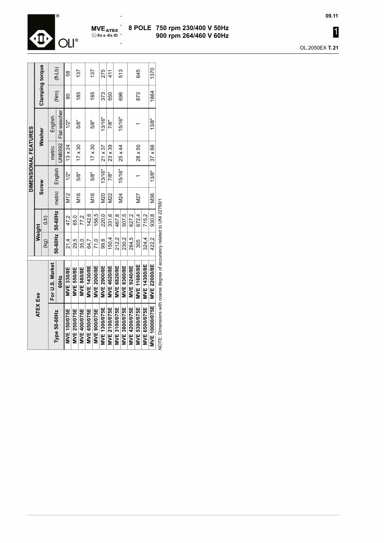
09.11
1
OL.2050EX T.
MVE
-
-
-
-Ex e -Ex tD
8 POLE 750 rpm 230/400 V 50Hz 900 rpm 264/460 V 60Hz
ATEX
Exe
DIM
ENSI
ON
AL F
EATU
RES
Wei
ght
Scre
wW
ashe
rC
lam
ping
torq
ue(k
g)(L
b)
Type
50-
60H
zFo
r U.S
. Mar
ket
50-6
0Hz
50-6
0Hz
met
ricE
nglis
hm
etric
Eng
lish
(Nm
)(ft
-Lb)
60H
zU
NI6
592
Flat
was
cher
MVE
150
/075
EM
VE 3
30/8
E21
,447
,2M
121/
2"13
x 2
41/
2"80
58M
VE 2
50/0
75E
MVE
550
/8E
29,5
65,0
M16
5/8"
17 x
30
5/8"
185
137
MVE
400
/075
EM
VE 8
80/8
E35
,077
,2M
VE 6
50/0
75E
MVE
143
0/8E
64,7
142,
6M
165/
8"17
x 3
05/
8"18
513
7M
VE 9
00/0
75E
MVE
200
0/8E
71,0
156,
5M
VE 1
300/
075E
MVE
290
0/8E
99,8
220,
0M
2013
/16"
21 x
37
13/1
6"37
327
5M
VE 2
100/
075E
MVE
462
0/8E
150,
433
1,6
M22
7/8"
23 x
39
7/8"
550
411
MVE
310
0/07
5EM
VE 6
820/
8E21
2,2
467,
8M
2415
/16"
25 x
44
15/1
6"69
651
3M
VE 3
800/
075E
MVE
836
0/8E
230,
250
7,5
MVE
420
0/07
5EM
VE 9
240/
8E28
4,5
627,
2M
271
28 x
50
187
364
5M
VE 5
300/
075E
MVE
116
60/8
E30
567
2,4
MVE
650
0/07
5EM
VE 1
4300
/8E
324,
471
5,2
MVE
100
00/0
75E
MVE
220
00/8
E42
2,2
930,
8M
3613
/8"
37 x
66
13/8
"18
6413
70N
OTE
: Dim
ensi
ons
with
coa
rse
degr
ee o
f acc
uran
cy re
late
d to
UN
I 227
68/1
21
MA
INTE
NA
NC
EA
ll rig
hts
rese
rved
© W
AM
GR
OU
P
2
CATALOGUE No. OL.2050EX M.
ISSUEB1
DATE OF LATEST UPDATE
CREATION DATE
09-2011CIRCULATION100
• ELECTRIC EXTERNAL MOTOVIBRATORS INSTALLATION, OPERATION AND MAINTENANCE
• ELEKTRISCHE AUSSENRÜTTLER EINBAU-,BETRIEBS-UND WARTUNGSANLEITUNG
• MOTOVIBRATEURS EXTERNES ELECTRIQUES INSTALLATION, UTILISATION ET ENTRETIEN
• MOTOVIBRATORI ELETTRICI ESTERNI INSTALLAZIONE, USO E MANUTENZIONE
MVE Ex e-Ex tD
II 2 GD Ex e II T3 Ex tD A21 T150°C IP66
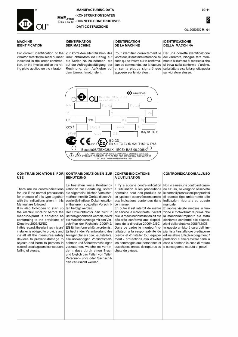
MVE
-
-
-
-
09.11
2
OL.2050EX M.
Ex e -Ex tD
IDENTIFICAZIONEDELLA MACCHINA
Per una corretta identificazione del vibratore, bisogna fare riferi-mento al numero di matricola che si trova sulla conferma d’ordine, sulla fattura e sulla targhetta posta sul vibratore stesso.
MANUFACTURING DATA
KONSTRUKTIONSDATEN
DONNÉES CONSTRUCTIVES
DATI COSTRUZIONE
CONTROINDICAZIONI ALL’USO
Non vi è nessuna controindicazio-ne all’uso, se vengono osservate le normali precauzioni per prodotti di questo tipo unitamente alle indicazioni riportate su questo manuale.E’ inoltre vietato mettere in fun-zione il motovibratore prima che la macchina/impianto sia stato dichiarato conforme alle disposi-zioni della direttiva 2006/42/CEIn questo ambito è cura dell’ im-piantista / installatore predisporre ed installare tutti gli accorgimenti / protezioni al fine di evitare danni a cose o persone in caso di rotture e conseguente caduta di pezzi.
KONTRAINDIKATIONEN ZUR BENUTZUNG
Es bestehen keine Kontraindi-kationen zur Benutzung, sofern die allgemein üblichen Vorsichts-maßnahmen für Geräte dieser Art sowie die in dieser Dokumentation enthaltenen, speziellen Vorschrif-ten befolgt werden. Der Unwuchtmotor darf nicht in Betrieb genommen werden, bevor die Maschine/Anlage mit den Vor-schriften der Richtlinie 2006/42/EG für konform erklärt worden ist.Es liegt in der Verantwortung des Anlagenplaners bzw. -aufstellers, alle notwendigen Vorsichtsmaß-nahmen und Schutzvorrichtungen vorzusehen, welche es verhin-dern, dass durch einen Bruch und folglich das Fallen von Teilen Personen- und/ oder Sachschä-den verursacht werden.
CONTRE-INDICATIONS A L’UTILISATION
Il n’y a aucune contre-indication à l’utilisation si les précautions normales pour des produits de ce type sont observées ensemble aux indications contenues dans ce manuel.En outre il est interdit de mettre en service le motovibrateur avant que la machine/installation ait été déclarée conforme aux disposi-tions de la directive 2006/42/ECDans ce cadre le monteur/ins-tallateur a la responsabilité de prévoir et d’installer tout équipe-ment / protections afin d’éviter les dommages aux personnes et aux choses en cas de ruptures ou chute de pièces.
CONTRAINDICATIONS FOR USE
There are no contraindications for use if the normal precautions for products of this type together with the indications given in this Manual are followed.It is also forbidden to start up the electric vibrator before the machine/plant is declared as conforming to the provisions of Directive 2006/42/ECIn this regard, the plant technician/installer is obliged to provide and install all the measures/safety devices to prevent damage to objects and harm to persons in case of breakage and consequent falling of pieces.
IDENTIFICATION DE LA MACHINE
Pour identifier correctement le vibrateur, il faut faire référence au code qui se trouve sur la confirma-tion de commande, sur la facture et sur la plaque signalétique apposée sur le vibrateur.
IDENTIFIKATION DER MASCHINE
Zur korrekten Identifikation des Unwuchtmotors ist Bezug auf die Serien-Nr. zu nehmen, die auf der Auftragsbestätigung, der Rechnung, dem Aufkleber auf dem Unwuchtmotor steht.
MACHINE IDENTIFICATION
For correct identification of the vibrator, refer to the serial number indicated in the order confirma-tion, on the invoice and on the rat-ing plate applied on the vibrator.
01
Baseefa06ATEX0281X - IECEx BAS 06.0068X
Fc.Kg
Medolla (MO)-Italywww.olivibra.it
CAUTION: USE SUPPLY WIRES AND CABLE ENTRIES SUITABLEFOR 80°C FROM SIZE 20 TO 50 AND FOR 100°C FROM SIZE 60 TO 90 DO NOT OPEN WHEN ENERGIZED
SIZEYEAR
0044
COS f
Hz
MVE
V
IA/IN
RPM
S.N.
Ex e II T3 Ex tD A21 T150°C IP66II 2 GD
Duty S1 CL. F
Fc.Lb
Tamb
Kw
A
Hp
Et
PH
WAMGROUPMade in EU
09.11
2
OL.2050EX M.
MVE
-
-
-
-Ex e -Ex tD
CONTROLLI PRIMA DELLA SPEDIZIONE
Evitate ogni tipo di danneggia-mento durante lo scarico e le movimentazioni; a tale scopo sollevare l’imballo come indicato nel seguente manuale. NON SPINGERE NÈ TRASCINARE il motovibratore elettrico! Tenete conto che si tratta di materiale meccanico/elettrico che deve essere movimentato con cura. Come modalità di ancoraggio durante il trasporto, l’imballo del motovibratore deve essere saldamente ancorato al pianale del mezzo per evitare movimenti e urti che potrebbero lesionare alcune parti; inoltre non devono essere presenti sul pianale corpi liberi che con urti potrebbero danneggiarle.
Al ricevimento della merce con-trollare se la tipologia e la quantità corrispondono con i dati della conferma d’ordine.
Eventuali danni devono essere fatti presenti immediatamente per iscritto nell’apposito spazio della lettera di vettura. L’autista è obbligato ad accettare tale recla-mo e lasciarne una copia a Voi. Se la fornitura è franco destino, inviate il Vs. reclamo al produt-tore, altrimenti direttamente allo spedizioniere.
Se non richiederete i danni imme-diatamente all’arrivo della merce, la vostra richiesta potrebbe non essere accolta.
Deve essere cura dell’installatore smaltire gli imballi in modo ade-guato secondo le leggi vigenti in materia.
CHECKING PRIOR TO SHIP-MENT
Avoid damage during unloading and handling; this is possible by lifting the pack as indicated in the Manual. DO NOT PUSH OR PULL the electric vibrator! Bear in mind that it is mechanical/electrical material and must be handled carefully.For anchoring during transport, fix the electric vibrator package firmly to the vehicle bed to prevent movement or impact which can damage parts; no parts must be left loose on the vehicle bed as they can be damaged by impact.
On receiving the goods, check to make sure the type and quantity correspond to the data in the order confirmation.
Damage, if any, must be imme-diately notified in writing in the space provided in the waybill. The driver of the vehicle is obliged to accept this complaint and leave the client a copy.If the supply is ex-destination, the Customer must send the complaint to the manufacturer, or directly to the haulage contractor.
No claims for damages will be accepted unless received imme-diately on receipt of the goods.
It shall be the installer’s responsi-bility to dispose off the packaging according to the legislation ap-plicable in the matter.
KONTROLLEN VOR DEM VER-SAND
Vermeiden Sie jede Art der Be-schädigung während Abladen und Handling. Zu diesem Zweck die Verpackung haben, wie es in dem folgenden Handbuch angegeben ist. Den elektrischen Unwuchtmotor weder SCHIEBEN NOCH ZIEHEN! Berücksichtigen Sie, dass es sich um mechanisches/elektrisches Material handelt, das mit Vorsicht gehandhabt werden muss.Als Verankerungsmodalität wäh-rend des Transports muss die Ver-packung des Unwuchtmotors fest an der Pritsche des Fahrzeugs befestigt werden, um Bewegun-gen und Stöße zu vermeiden, die einige Teile beschädigen könnten. Außerdem dürfen auf der Pritsche keine freien Körper vorhanden sein, die durch Stöße Beschä-digungen verursachen könnten.
Bei Erhalt der Ware prüfen, ob der Typ und die Menge der Ware der Auftragsbestätigung entsprechen.
Etwaige Schäden müssen sofort in der Schriftform, und zwar auf dem Abschnitt des Frachtbriefes angegeben werden. Der Fahrer ist verpflichtet, diese Reklamati-on anzunehmen und Ihnen eine Kopie auszuhändigen.Wenn die Lieferung frei Haus erfolgt, senden Sie ihre Reklama-tion an den Hersteller, ansonsten direkt an den Spediteur.
Wenn Sie die Schäden nicht sofort bei der Ankunft der Ware reklamieren, könnte Ihre Anfrage sonst später nicht mehr angenom-men werden.
Der Installateur hat für das Entsor-gen der Verpackungen zu sorgen, und zwar in Übereinstimmung mit den geltenden Gesetzen.
CONTROLES AVANT L’EXPÉ-DITION
Eviter tout type de dégât pendant le déchargement et la manuten-tion ; pour cela soulever l’embal-lage comme indiqué dans ce manuel. NE PAS POUSSER, NI TRAINER le motovibrateur électrique ! Tenir compte du fait qu’il s’agit de matériel mécanique/électrique qui doit être manutentionné avec soin.Pendant le transport l’emballage du motovibrateur doit être fixé so-lidement au plateau du moyen de transport pour éviter les mouve-ments ou les chocs qui pourraient abîmer certaines parties. En outre sur le plateau il ne doit pas y avoir de corps libres pouvant bouger et donc les endommager.
Au moment de la réception de la marchandise contrôler si la typo-logie et la quantité correspondent aux données de la confirmation de commande.
Les dégâts éventuels doivent être immédiatement mentionnés par écrit dans l’espace prévu sur la lettre de voiture. Le chauffeur a l’obligation d’accepter cette réclamation et de vous en laisser une copie.Si la fourniture est franco destina-tion, adressez votre réclamation au producteur, sinon directement au transporteur.
Si vous ne faites pas immédia-tement la demande tout de suite après l’arrivée de la marchandise, votre demande pourrait ne pas être acceptée.
L’installateur a l’obligation d’élimi-ner les emballages conformément aux lois en vigueur en la matière.
TRANSPORT AND PACKING
TRANSPORT UND VERPACKUNG
TRANSPORT ET EMBALLAGE
TRASPORTO E IMBALLO02

MVE
-
-
-
-
09.11
2
OL.2050EX M.
Ex e -Ex tD
- L’utilizzatore dovrà assicurarsi che l’impianto all’interno del quale verrà installato il motovibratore elettrico sia stato adeguatamente messo in sicurezza da un punto di vista di rischio esplosione prima di essere avviato e che inoltre sia stato redatto il “documento sulla protezione contro le esplosioni” come previsto dalla Direttiva ATEX 99/92/CE.
- La macchina non necessita di un’il-luminazione particolare; l’installa-tore della macchina è comunque tenuto ad assicurare la presenza di un’omogenea illuminazione nell’area in base alle indicazioni della normativa pertinente.
IL MOTOVIBRATORE DEVE ESSERE INSTALLATO ESCLU-SIVAMENTE DA PERSONALE SPECIALIZZATO.
- Prima dell’installazione, soprat-tutto se l’apparecchio è rimasto a magazzino per molto tempo (oltre 24 mesi), consigliamo di rimuovere uno dei coperchi laterali di prote-zione delle masse e controllare che l’albero ruoti liberamente.
- Controllare inoltre l’isolamento del motore, utilizzando un “Prova Rigidità”, alla tensione di circa 2 KV per un tempo non superiore ai 5 secondi tra fase e fase e 10 secondi tra fase e massa. (fig.1)
- Qualora vengano riscontrate anomalie, contattare la ditta pro-duttrice.
- Il motovibratore MVE può essere installato in qualsiasi posizione. Si consiglia di fissare il motovibratore su una zona rigida per evitare che le vibrazioni indotte provochino rotture o incrinature; se ciò non fosse possibile, è necessario utilizzare piastre e nervature di rinforzo. Le procedure di taglio e di saldatura devono essere ef-fettuate da personale qualificato. Idonee procedure di Hot-Works, (quali taglio, saldatura…) e LOTO – lockout/tagout: procedura di disconnessione della macchina (segregazione elettrica e mecca-nica), dovranno essere applicate per l’installazione in sicurezza del vibratore elettrico. L’autorizzazio-ne all’esecuzione dei lavori a caldo DEVE essere data da personale tecnico specializzato e formato sul rischio esplosione da polveri (in grado di verificare il rischio residuo, l’idoneità degli utensili la conoscenza delle procedure).
INSTALLATION
EINBAU
INSTALLATION
INSTALLAZIONE
- The user must make sure the plant in which the electric vibrator is installed is set in safe condi-tion from the point of view of risk of explosion before it is started up and that the “document on protection against explosions” is also prepared, as required by ATEX Directive 99/92/CE.
- The machine does not require spe-cial lighting; the machine installer is however required to make sure there is uniform lighting in the area according to the relevant standards.
THE ELECTRIC VIBRATOR MUST BE INSTALLED EXCLUSIVELY BY SPECIALIST PERSONNEL.
- Before installation, especially if the apparatus has remained for long in the warehouse (exceeding 24 months), remove one of the side covers from the weights and check to make sure the shaft turns freely.
- Also check the motor isolation, us-ing a “Rigidity Test”, at a voltage of approx. 2 kV for a maximum time of 5 seconds between phases and 10 seconds between phase and earth. (fig.1)
- In the event of faults, contact the manufacturer.
- The MVE electric vibrator can be installed in any position.
Fix the electric vibrator on a rigid area to avoid induced vibrations causing breakage or cracks; if this is not possible, use plates and ribbing for reinforcement.
Cutting and welding procedures must be carried out by qualified personnel.
Suitable Hot- Works, (like cutting, welding…) and LOTO – lockout/tagout: procedure for disconnect-ing the machine (electrical and mechanical segregation), must be applied for safe installation of the electric vibrator. Authorization for Hot works MUST be given by spe-cialist trained personnel familiar with the risk of explosion of pow-ders (capable of checking residual risk, the suitability of tools and familiarity with the procedures).
- Der Anwender muss sicherstellen, dass die Anlage, in die der elek-trische Unwuchtmotor installiert werden soll, angemessen in einen sicheren Zustand gebracht worden ist, was die Explosionsgefahr angeht, bevor er in Betrieb genommen wird, und dass außerdem das „Explosi-onsschutzdokument” geschrieben worden ist, so wie es die ATEX- Richtlinie 99/92/EG vorsieht.
- Die Maschine verlangt keine beson-dere Beleuchtung. Der Installateur der Maschine ist allerdings dazu an-gehalten, das Vorhandensein einer gleichmäßigen Ausleuchtung des Bereichs aufgrund der einschlägigen Bestimmungen zu gewährleisten.
DER UNWUCHTMOTOR DARF NUR DURCH SPEZIALISIERTES PERSONAL INSTALLIERT WER-DEN.
- Vor der Installation, vor allem wenn das Gerät längere Zeit auf Lager ge-halten worden ist (über 24 Monate), sollte man eine der beiden seitlichen Schutzhauben der Fliehgewichte ab-nehmen und prüfen, dass die Welle sich frei drehen kann.
- Außerdem die Isolierung des Motors prüfen, indem man einen „Durch-schlagfestigkeitstester” benutzt, und zwar bei der Spannung von ca. 2 kV für eine Zeit von nicht mehr als 5 Sekunden zwischen den Phasen und von 10 Sekunden zwischen Phase und Masse (Abb. 1).
- Falls Mängel festgestellt werden, wenden Sie sich an den Hersteller.
- Der Unwuchtmotor MVE kann in jeder beliebigen Position eingebaut werden.
Es empfiehlt sich, den Unwucht-motor in einem starren Bereich zu befestigen, um zu vermeiden, dass die erzeugten Schwingungen Brüche oder Risse verursachen. Sollte das nicht möglich sein, ist es erforderlich, Verstärkungsplatten und -rippen zu benutzen.
Schnitt- und Schweißarbeiten müs-sen durch qualifiziertes Personal ausgeführt werden.
Geeignete Verfahren für Warmarbei-ten (wie Brennschneiden, Schwei-ßen etc.) und LOTO – lockout/tagout (Abschaltung/Absperrung), d.h. Verfahren zum Abtrennen der Ma-schine (elektrische und mechanische Abtrennung) müssen für die sichere Installation des elektrischen Un-wuchtmotors angewendet werden. Die Genehmigung zur Ausführung der Warmarbeiten MUSS von spe-zialisiertem technischem Personal gegeben werden, das über die Staubexplosionsgefahr ausgebildet ist (in der Lage, das Restrisiko, die Eignung der Werkzeuge und die Kenntnis der Verfahren zu prüfen).
- L’utilisateur devra s’assurer que l’équipement dans lequel sera installé le motovibrateur électrique a été mis en sécurité du point de vue des risques d’explosion avant d’être mis en marche et que le “document sur la protection contre les explosions” a été rédigé comme prévu par la Direc-tive ATEX 99/92/CE.
- La machine n’exige pas un éclai-rage particulier, l’installateur de la machine est tenu de garantir un éclairage homogène dans la zone conformément aux indications de la norme correspondante.
LE MOTOVIBRATEUR DOIT ÊTRE INSTALLÉ EXCLUSIVEMENT PAR DU PERSONNEL SPÉCIALISÉ.
- Avant la mis en place, surtout si l’appareil est resté entreposé pen-dant longtemps (plus de 24 mois), nous conseillons d’enlever un des couvercles latéraux de protection des masses et de contrôler que l’arbre tourne librement.
- Contrôler aussi l’isolation du moteur, en utilisant un « Essai Rigidité » , à la tension de 2 KV environ pendant une durée qui ne dépasse pas 5 secondes entre les phases et 10 secondes entre la phase et la masse. (fig.1)
- En cas d’anomalies, contacter le producteur.
- Le motovibrateur MVE peut être installé dans n’importe quelle position.
On conseille de fixer le motovi-brateur sur une partie rigide pour éviter que les vibrations induites provoquent des ruptures ou des fissures ; si cela n’est pas pos-sible, utiliser des plaques et des nervures de renfort.
Les procédures de découpe et de soudage doivent être faites par du personnel qualifié.
Des procédures appropriées de travail à haute température Hot Works, (tel que découpe, sou-dure...) et LOTO - lockout/tagout : la procédure de déconnection de la machine (séparation électrique et mécanique), devra être appli-quée pour la mise en sécurité du vibrateur électrique. L’autorisa-tion pour exécuter les travaux à chaud DOIT être donnée par du personnel technique spécialisé et formé sur le risque explosion des poussières (en mesure de vérifier le risque résiduel, l’aptitude des outils, la connaissance des pro-cédures).
03
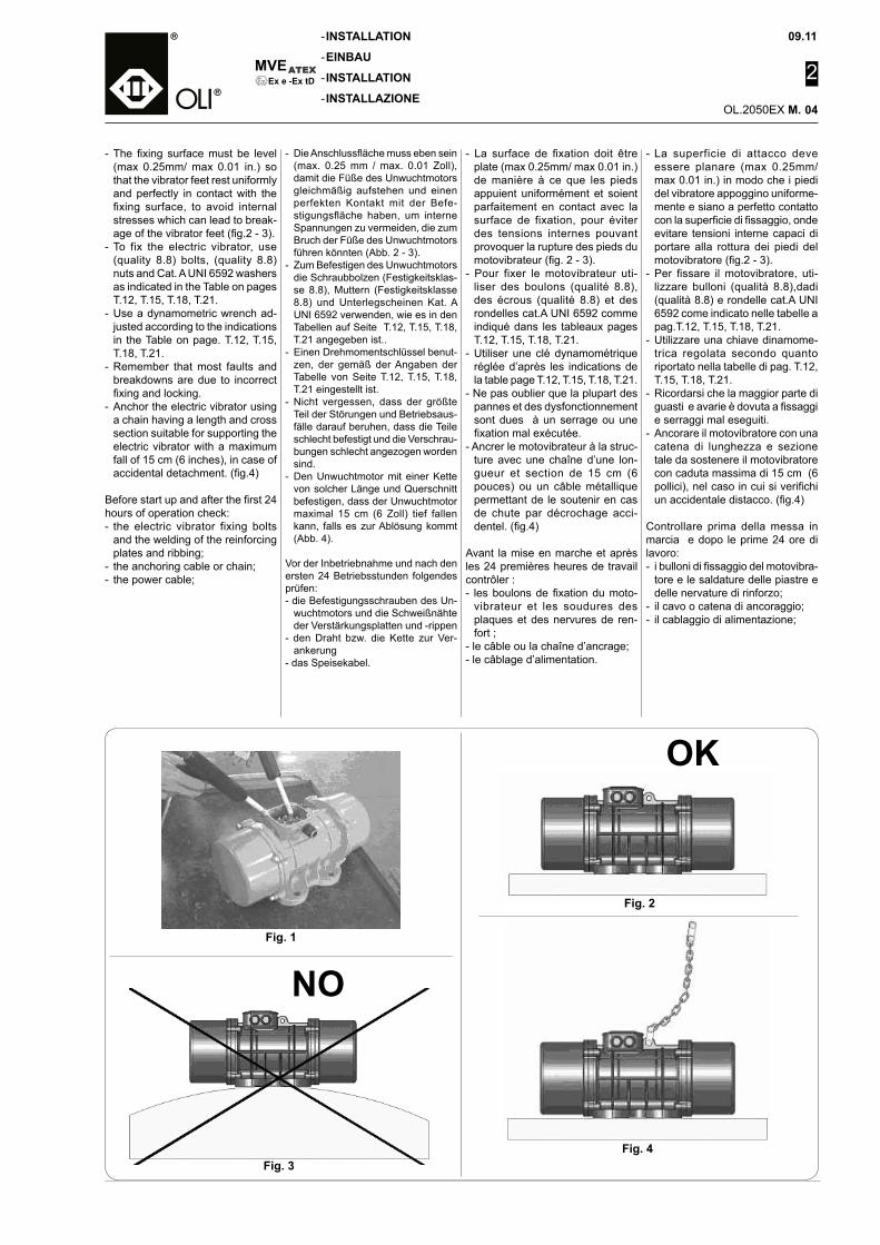
09.11
2
OL.2050EX M.
MVE
-
-
-
-Ex e -Ex tD
- La superficie di attacco deve essere planare (max 0.25mm/max 0.01 in.) in modo che i piedi del vibratore appoggino uniforme-mente e siano a perfetto contatto con la superficie di fissaggio, onde evitare tensioni interne capaci di portare alla rottura dei piedi del motovibratore (fig.2 - 3).
- Per fissare il motovibratore, uti-lizzare bulloni (qualità 8.8),dadi (qualità 8.8) e rondelle cat.A UNI 6592 come indicato nelle tabelle a pag.T.12, T.15, T.18, T.21.
- Utilizzare una chiave dinamome-trica regolata secondo quanto riportato nella tabelle di pag. T.12, T.15, T.18, T.21.
- Ricordarsi che la maggior parte di guasti e avarie è dovuta a fissaggi e serraggi mal eseguiti.
- Ancorare il motovibratore con una catena di lunghezza e sezione tale da sostenere il motovibratore con caduta massima di 15 cm (6 pollici), nel caso in cui si verifichi un accidentale distacco. (fig.4)
Controllare prima della messa in marcia e dopo le prime 24 ore di lavoro:- i bulloni di fissaggio del motovibra-
tore e le saldature delle piastre e delle nervature di rinforzo;
- il cavo o catena di ancoraggio;- il cablaggio di alimentazione;
INSTALLATION
EINBAU
INSTALLATION
INSTALLAZIONE
Fig. 1
Fig. 2
Fig. 3Fig. 4
OK
NO
- La surface de fixation doit être plate (max 0.25mm/ max 0.01 in.)de manière à ce que les pieds appuient uniformément et soient parfaitement en contact avec la surface de fixation, pour éviter des tensions internes pouvant provoquer la rupture des pieds du motovibrateur (fig. 2 - 3).
- Pour fixer le motovibrateur uti-liser des boulons (qualité 8.8), des écrous (qualité 8.8) et des rondelles cat.A UNI 6592 comme indiqué dans les tableaux pages T.12, T.15, T.18, T.21.
- Utiliser une clé dynamométrique réglée d’après les indications de la table page T.12, T.15, T.18, T.21.
- Ne pas oublier que la plupart des pannes et des dysfonctionnement sont dues à un serrage ou une fixation mal exécutée.
- Ancrer le motovibrateur à la struc-ture avec une chaîne d’une lon-gueur et section de 15 cm (6 pouces) ou un câble métallique permettant de le soutenir en cas de chute par décrochage acci-dentel. (fig.4)
Avant la mise en marche et après les 24 premières heures de travail contrôler :- les boulons de fixation du moto-
vibrateur et les soudures des plaques et des nervures de ren-fort ;
- le câble ou la chaîne d’ancrage;- le câblage d’alimentation.
- Die Anschlussfläche muss eben sein (max. 0.25 mm / max. 0.01 Zoll), damit die Füße des Unwuchtmotors gleichmäßig aufstehen und einen perfekten Kontakt mit der Befe-stigungsfläche haben, um interne Spannungen zu vermeiden, die zum Bruch der Füße des Unwuchtmotors führen könnten (Abb. 2 - 3).
- Zum Befestigen des Unwuchtmotors die Schraubbolzen (Festigkeitsklas-se 8.8), Muttern (Festigkeitsklasse 8.8) und Unterlegscheinen Kat. A UNI 6592 verwenden, wie es in den Tabellen auf Seite T.12, T.15, T.18, T.21 angegeben ist..
- Einen Drehmomentschlüssel benut-zen, der gemäß der Angaben der Tabelle von Seite T.12, T.15, T.18, T.21 eingestellt ist.
- Nicht vergessen, dass der größte Teil der Störungen und Betriebsaus-fälle darauf beruhen, dass die Teile schlecht befestigt und die Verschrau-bungen schlecht angezogen worden sind.
- Den Unwuchtmotor mit einer Kette von solcher Länge und Querschnitt befestigen, dass der Unwuchtmotor maximal 15 cm (6 Zoll) tief fallen kann, falls es zur Ablösung kommt (Abb. 4).
Vor der Inbetriebnahme und nach den ersten 24 Betriebsstunden folgendes prüfen:- die Befestigungsschrauben des Un-
wuchtmotors und die Schweißnähte der Verstärkungsplatten und -rippen
- den Draht bzw. die Kette zur Ver-ankerung
- das Speisekabel.
- The fixing surface must be level (max 0.25mm/ max 0.01 in.) so that the vibrator feet rest uniformly and perfectly in contact with the fixing surface, to avoid internal stresses which can lead to break-age of the vibrator feet (fig.2 - 3).
- To fix the electric vibrator, use (quality 8.8) bolts, (quality 8.8) nuts and Cat. A UNI 6592 washers as indicated in the Table on pages T.12, T.15, T.18, T.21.
- Use a dynamometric wrench ad-justed according to the indications in the Table on page. T.12, T.15, T.18, T.21.
- Remember that most faults and breakdowns are due to incorrect fixing and locking.
- Anchor the electric vibrator using a chain having a length and cross section suitable for supporting the electric vibrator with a maximum fall of 15 cm (6 inches), in case of accidental detachment. (fig.4)
Before start up and after the first 24 hours of operation check:- the electric vibrator fixing bolts
and the welding of the reinforcing plates and ribbing;
- the anchoring cable or chain;- the power cable;
04
MVE
-
-
-
-
09.11
2
OL.2050EX M.
Ex e -Ex tD
ELECTRICAL CONNECTIONS
ELEKTRISCHE ANSCHLÜSSE
RACCORDEMENTS ÉLECTRIQUES
COLLEGAMENTI ELETTRICI
IL COLLEGAMENTO ELETTRI-CO DEVE ESSERE EFFETTUA-TO ESCLUSIVAMENTE DA PER-SONALE QUALIFICATO E CON ALIMENTAZIONE DISINSERITA.
La rete di alimentazione ed il colle-gamento dei motovibratori devono essere conformi alle vigenti norme di sicurezza stabilite dalle autorità competenti del luogo dove si svol-ge l’attività.- Accertarsi che la tensione di
rete sia la stessa indicata sulla targhetta posta sul motovibratore
- Scollegare la linea prima di eseguire eventuali manuten-zioni o durante la regolazione delle masse. Ogni riparazione o sostituzione di componenti deve essere effettuata solamente da personale specializzato.
- Utilizzare cavo di alimentazione flessibile a 4 conduttori, di cui uno giallo-verde (solo verde per gli U.S.A.) utilizzato per la messa a terra. Nel collegamento del motovibratore alla linea , il cavo giallo-verde della terra deve essere sempre il più lungo per evitare che si rompa per primo in caso di cedimento.
- Gli elementi di connessione per la messa a terra o per il collegamento equipotenziale delle masse devono permettere il collegamento efficace di almeno un conduttore di sezione come indicato nella tabella sottostante.
In caso di sostituzione del pres-sacavo è OBBLIGATORIO che il nuovo pressacavo impiegato sia conforme alla direttiva ATEX II 2 GD
THE ELECTRICAL CONNEC-TIONS MUST BE MADE EXCLU-SIVELY BY QUALIFIED PER-SONNEL, WITH THE POWER SUPPLY DISCONNECTED.
The power supply mains and connection of the electric vibra-tors must be in conformity to the safety standards established by the competent authorities of the place in which the operations are carried out.- Check to make sure the mains
voltage is the same as that in-dicated on the electric vibrator rating plate.
- Disconnect the line before car-rying out maintenance or while adjusting the weights. All repairs or replacement of components must be carried out exclusively by specialist personnel.
- Use a flexible power cable with 4 wires, one of which is yellow-green (green only for the U.S.A.) used for earthing. While con-necting the electric vibrator to the line, the yellow-green earth wire must always be longer to prevent it breaking first, in the event of yielding.
- The elements for the earth con-nection or for equipotential con-nection of the weights must allow effective connection of at least one wire having cross section as indicated in the Table below.
For replacing cable glands, the new cable gland used MUST conform to ATEX Directive II 2 GD
D E R E L E K T R I S C H E A N -SCHLUSS DARF NUR DURCH QUALIFIZIERTES PERSONAL UND BEI AUSGESCHALTETER STROMVERSORGUNG AUSGE-FÜHRT WERDEN.
Das Stromnetz und der Anschluss der Unwuchtmotoren müssen den geltenden Sicherheitsbestimmun-gen entsprechen, die von den zuständigen Behörden der Ortes, wo die Tätigkeit ausgeführt wird, festgelegt worden sind.- Sicherstellen, dass die Netzspan-
nung die gleiche ist, die auf dem Typenschild des Unwuchtmotors steht.
- Die Leitung abtrennen, bevor man irgendwelche Wartungen ausführt oder die Fliehgewichte regelt. Alle Reparaturen oder Ersetzungen von Komponenten dürfen nur von spezialisiertem Personal ausgeführt werden.
- Ein biegsames Speisekabel mit 4 Leitern benutzen, von denen einer gelbgrün ist (in den USA nur grün) und für die Erdung ver-wendet wird. Beim Anschluss des Unwuchtmotors an die Leitung ist das gelbgrüne Erdungskabel immer länger zu halten, um zu vermeiden, dass es beim Nach-geben zuerst reißt.
- Die Anschlusselemente für die Erdung oder den potentialfreien Anschluss der Fliehgewichte müssen den effizienten An-schluss von wenigstens einem Leiter mit Querschnitt wie in der folgenden Tabelle ermöglichen.
Beim Ersetzen der Kabelver-schraubung ist es OBLIGATO-RISCH vorgeschrieben, dass die neue Kabelverschraubung der ATEX-Richtlinie II 2 GD entspricht.
LE RACCORDEMENT ELEC-TRIQUE DOIT ETRE EFFECTUE EXCLUSIVEMENT PAR DU PER-SONNEL QUALIFIE ET AVEC ALIMENTATION DEBRANCHEE. LE RACCORDEMENT A LA TERRE EST OBLIGATOIRE.
Le réseau d’alimentation et le raccordement des motovibra-teurs doivent être conformes aux normes de sécurité en vigueur éta-blies par les autorités compétentes du lieu où se déroule l’activité.- S’assurer que la tension du
secteur est la même de celle indiquée sur la plaque apposée sur le motovibrateur.
- Débrancher la ligne avant d’effec-tuer l’entretien ou le réglage des masses. Chaque réparation ou remplacement de composant doit être effectué seulement par du personnel spécialisé.
- Utiliser un câble d’alimentation flexible à 4 conducteurs, dont un jaune-vert (vert aux Etats-Unis) pour la mise à la terre. Lors du branchement du motovibrateur à la ligne, le câble jaune-vert de la terre doit toujours être plus long afin d’éviter qu’il ne se coupe en premier en cas de chute.
- Les éléments de connexion de mise à la terre ou pour la liaison équipotentielle des masses doivent permettre le raccorde-ment efficace d’au moins un conducteur de section comme indiqué dans le tableau ci-des-sous.
En cas de remplacement du presse-étoupe il est OBLIGA-TOIRE que le nouveau presse-étoupe employée soit conforme à la directive ATEX II 2 GD
05
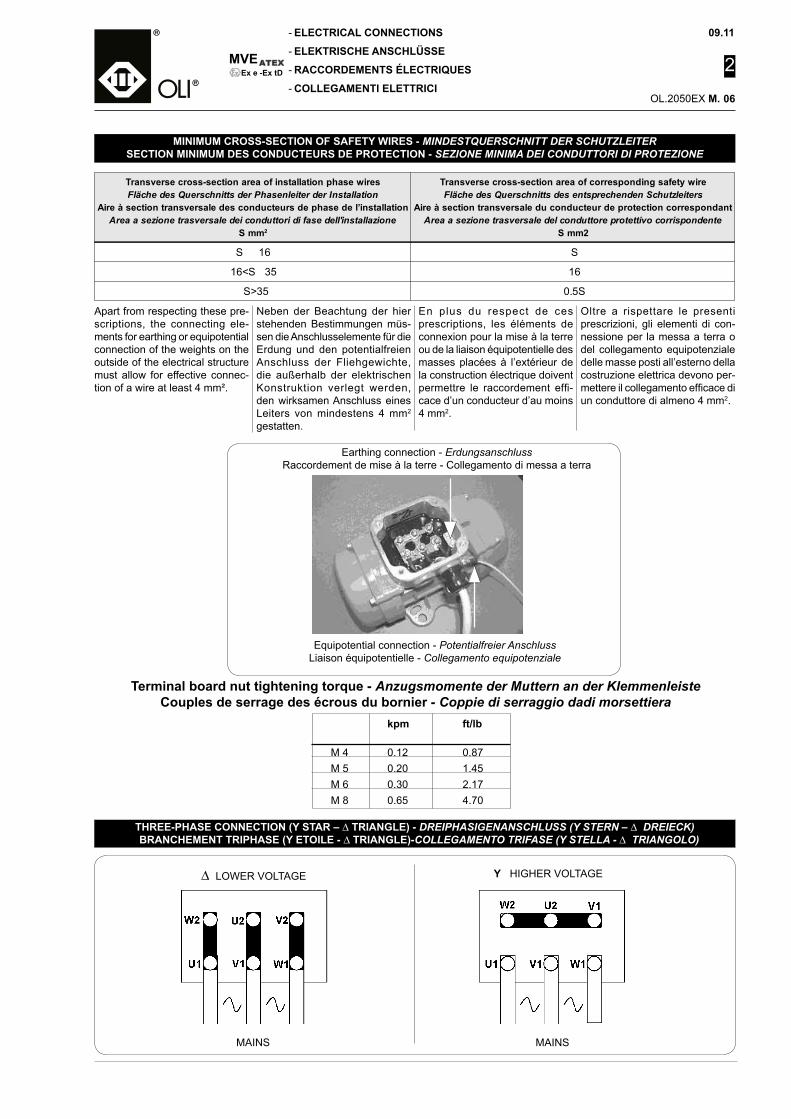
09.11
2
OL.2050EX M.
MVE
-
-
-
-Ex e -Ex tD
Transverse cross-section area of installation phase wiresFläche des Querschnitts der Phasenleiter der Installation
Aire à section transversale des conducteurs de phase de l’installationArea a sezione trasversale dei conduttori di fase dell'installazione
S mm2
Transverse cross-section area of corresponding safety wireFläche des Querschnitts des entsprechenden Schutzleiters
Aire à section transversale du conducteur de protection correspondantArea a sezione trasversale del conduttore protettivo corrispondente
S mm2
S 16 S
16<S 35 16
S>35 0.5S
MINIMUM CROSS-SECTION OF SAFETY WIRES - MINDESTQUERSCHNITT DER SCHUTZLEITERSECTION MINIMUM DES CONDUCTEURS DE PROTECTION - SEZIONE MINIMA DEI CONDUTTORI DI PROTEZIONE
Oltre a rispettare le presenti prescrizioni, gli elementi di con-nessione per la messa a terra o del collegamento equipotenziale delle masse posti all’esterno della costruzione elettrica devono per-mettere il collegamento efficace di un conduttore di almeno 4 mm2.
Equipotential connection - Potentialfreier AnschlussLiaison équipotentielle - Collegamento equipotenziale
Earthing connection - ErdungsanschlussRaccordement de mise à la terre - Collegamento di messa a terra
Terminal board nut tightening torque - Anzugsmomente der Muttern an der KlemmenleisteCouples de serrage des écrous du bornier - Coppie di serraggio dadi morsettiera
kpm ft/lb M 4 0.12 0.87 M 5 0.20 1.45 M 6 0.30 2.17 M 8 0.65 4.70
ELECTRICAL CONNECTIONS
ELEKTRISCHE ANSCHLÜSSE
RACCORDEMENTS ÉLECTRIQUES
COLLEGAMENTI ELETTRICI
Apart from respecting these pre-scriptions, the connecting ele-ments for earthing or equipotential connection of the weights on the outside of the electrical structure must allow for effective connec-tion of a wire at least 4 mm².
Neben der Beachtung der hier stehenden Bestimmungen müs-sen die Anschlusselemente für die Erdung und den potentialfreien Anschluss der Fliehgewichte, die außerhalb der elektrischen Konstruktion verlegt werden, den wirksamen Anschluss eines Leiters von mindestens 4 mm2 gestatten.
En plus du respect de ces prescriptions, les éléments de connexion pour la mise à la terre ou de la liaison équipotentielle des masses placées à l’extérieur de la construction électrique doivent permettre le raccordement effi-cace d’un conducteur d’au moins 4 mm2.
∆ LOWER VOLTAGE Y HIGHER VOLTAGE
MAINS MAINS
THREE-PHASE CONNECTION (Y STAR – ∆ TRIANGLE) - DREIPHASIGENANSCHLUSS (Y STERN – ∆ DREIECK) BRANCHEMENT TRIPHASE (Y ETOILE - ∆ TRIANGLE)-COLLEGAMENTO TRIFASE (Y STELLA - ∆ TRIANGOLO)
06
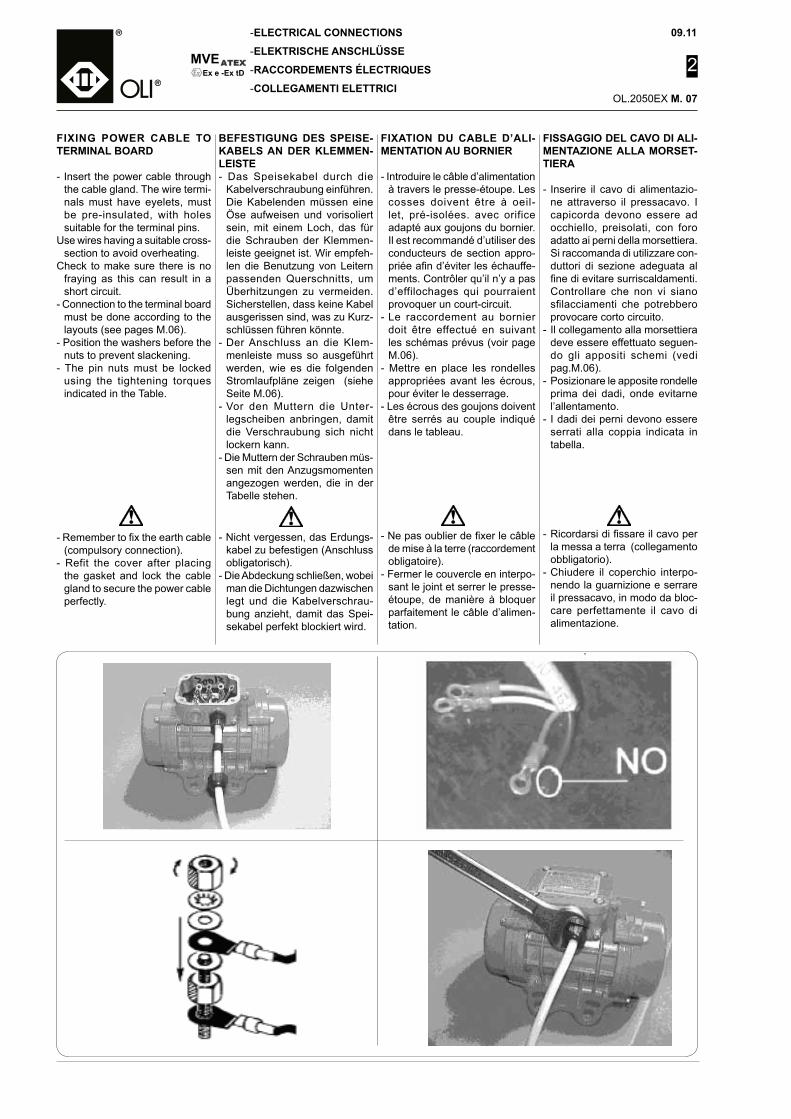
MVE
-
-
-
-
09.11
2
OL.2050EX M.
Ex e -Ex tD
FISSAGGIO DEL CAVO DI ALI-MENTAZIONE ALLA MORSET-TIERA
- Inserire il cavo di alimentazio-ne attraverso il pressacavo. I capicorda devono essere ad occhiello, preisolati, con foro adatto ai perni della morsettiera. Si raccomanda di utilizzare con-duttori di sezione adeguata al fine di evitare surriscaldamenti. Controllare che non vi siano sfilacciamenti che potrebbero provocare corto circuito.
- Il collegamento alla morsettiera deve essere effettuato seguen-do gli appositi schemi (vedi pag.M.06).
- Posizionare le apposite rondelle prima dei dadi, onde evitarne l’allentamento.
- I dadi dei perni devono essere serrati alla coppia indicata in tabella.
ELECTRICAL CONNECTIONS
ELEKTRISCHE ANSCHLÜSSE
RACCORDEMENTS ÉLECTRIQUES
COLLEGAMENTI ELETTRICI
FIXING POWER CABLE TO TERMINAL BOARD
- Insert the power cable through the cable gland. The wire termi-nals must have eyelets, must be pre-insulated, with holes suitable for the terminal pins.
Use wires having a suitable cross-section to avoid overheating.
Check to make sure there is no fraying as this can result in a short circuit.
- Connection to the terminal board must be done according to the layouts (see pages M.06).
- Position the washers before the nuts to prevent slackening.
- The pin nuts must be locked using the tightening torques indicated in the Table.
BEFESTIGUNG DES SPEISE-KABELS AN DER KLEMMEN-LEISTE- Das Speisekabel durch die
Kabelverschraubung einführen. Die Kabelenden müssen eine Öse aufweisen und vorisoliert sein, mit einem Loch, das für die Schrauben der Klemmen-leiste geeignet ist. Wir empfeh-len die Benutzung von Leitern passenden Querschnitts, um Überhitzungen zu vermeiden. Sicherstellen, dass keine Kabel ausgerissen sind, was zu Kurz-schlüssen führen könnte.
- Der Anschluss an die Klem-menleiste muss so ausgeführt werden, wie es die folgenden Stromlaufpläne zeigen (siehe Seite M.06).
- Vor den Muttern die Unter-legscheiben anbringen, damit die Verschraubung sich nicht lockern kann.
- Die Muttern der Schrauben müs-sen mit den Anzugsmomenten angezogen werden, die in der Tabelle stehen.
FIXATION DU CABLE D’ALI-MENTATION AU BORNIER
- Introduire le câble d’alimentation à travers le presse-étoupe. Les cosses doivent être à oeil-let, pré-isolées. avec orifice adapté aux goujons du bornier. Il est recommandé d’utiliser des conducteurs de section appro-priée afin d’éviter les échauffe-ments. Contrôler qu’il n’y a pas d’effilochages qui pourraient provoquer un court-circuit.
- Le raccordement au bornier doit être effectué en suivant les schémas prévus (voir page M.06).
- Mettre en place les rondelles appropriées avant les écrous, pour éviter le desserrage.
- Les écrous des goujons doivent être serrés au couple indiqué dans le tableau.
- Ne pas oublier de fixer le câble de mise à la terre (raccordement obligatoire).
- Fermer le couvercle en interpo-sant le joint et serrer le presse-étoupe, de manière à bloquer parfaitement le câble d’alimen-tation.
- Nicht vergessen, das Erdungs-kabel zu befestigen (Anschluss obligatorisch).
- Die Abdeckung schließen, wobei man die Dichtungen dazwischen legt und die Kabelverschrau-bung anzieht, damit das Spei-sekabel perfekt blockiert wird.
- Ricordarsi di fissare il cavo per la messa a terra (collegamento obbligatorio).
- Chiudere il coperchio interpo-nendo la guarnizione e serrare il pressacavo, in modo da bloc-care perfettamente il cavo di alimentazione.
- Remember to fix the earth cable (compulsory connection).
- Refit the cover after placing the gasket and lock the cable gland to secure the power cable perfectly.
07
09.11
2
OL.2050EX M.
MVE
-
-
-
-Ex e -Ex tD
IL COLLEGAMENTO ELETTRI-CO DEVE ESSERE EFFETTUA-TO ESCLUSIVAMENTE DA PER-SONALE QUALIFICATO E CON ALIMENTAZIONE DISINSERITA.
Controllare che la tensione e la frequenza corrispondano a quella indicata nella targa di identifica-zione del motovibratore.Quando i motovibratori vengono installati in coppia, ognuno di essi deve essere provvisto di una propria protezione esterna di sovraccarico, le quali devono essere interbloccate tra loro, onde evitare il funzionamento di un solo motovibratore in caso di arresto accidentale dell’altro. Utilizzare sempre magnetotermici ad intervento ritardato, in modo da evitarne l’intervento durante la fase di avviamento, nella quale la corrente assorbita può raggiun-gere livelli elevati (soprattutto in presenza di basse temperature).Protezione al sovraccarico NON SUPERIORE al 10% dei dati di targa, pena il decadimento della garanzia!
Tutta la componentistica elettrica che l’installatore andrà ad inserire nel motovibratore elettrico (es. protezioni per il sovraccarico, sensori…) dovrà essere conforme alla direttiva ATEX 94/9/CE.- categoria II 2 G/D o superiore
per l’esterno (per zona 21, zona 1).
- Per il collegamento del moto-vibratore in equipotenzialità, collegare la macchina a terra utilizzando l’apposito morsetto presente sulla carcassa
NOTA: Fare attenzione che la guarnizione del coperchio della morsettiera sia posizionata cor-rettamente; un errato posiziona-mento potrebbe alterare il grado di protezione IP.
ELECTRICAL CONNECTIONS
ELEKTRISCHE ANSCHLÜSSE
RACCORDEMENTS ÉLECTRIQUES
COLLEGAMENTI ELETTRICI
ELECTRICAL CONNECTIONS MUST BE MADE EXCLUSIVELY BY QUALIFIED PERSONNEL WITH THE POWER SUPPLY SWITCHED OFF.
Check to make sure the voltage and frequency correspond to the values indicated on the electric vibrator identification plate.When electric vibrators are in-stalled in pairs, each of these must have its own external overload protection, and the two must be interlocked to prevent working of a single vibrator if the other stops accidentally. Always use delayed-action magnetothermal cut-outs to prevent activation dur-ing the start up phase, when the power draw can reach very high levels (especially at low tempera-tures). Overload protection NOT HIGHER THAN 10% of the plate data, failing which the warrantee will lapse!
All the electrical components the installer intends installing in the electric vibrator (such as overload protection, sensors…) must con-form to ATEX Directive 94/ 9/CE.
- category II 2 G/D or greater for the outdoors (for zone 21, zone 1).
- For connecting the electric vibra-tor in equipotential, connect the machine to earth using the spe-cial clamp provided on the body.
NOTE: Check to make sure the terminal board cover gasket is positioned correctly, as incorrect positioning can alter the degree of protection.
D ER ELEK TR ISC H E A N -SCHLUSS DARF NUR DURCH QUALIFIZIERTES PERSONAL UND BEI AUSGESCHALTETER STROMVERSORGUNG AUSGE-FÜHRT WERDEN.
Sicherstellen, dass die Spannung und die Frequenz den Werten ent-spricht, die auf dem Typenschild des Unwuchtmotors stehen.Wenn die Unwuchtmotoren paar-weise installiert werden, hat jeder davon einen eigenen Schutz ge-gen Überlastung. Diese müssen miteinander verbunden werden, um zu vermeiden, dass nur ein Unwuchtmotor funktioniert, falls der andere unvorhergesehen zum Stehen kommt. Immer Mo-torschutzschalter mit verzögerter Auslösung benutzen, damit die Auslösung während der Start-phase vermieden wird, in der die Stromaufnahme sehr hohe Werte erreichen kann (vor allem beim Vorliegen tiefer Temperaturen). Überlastschutz NICHT ÜBER 10 % der Typenschilddaten, weil sonst die Garantie verfällt!
Alle elektrischen Komponenten, die der Installateur in den elek-trischen Unwuchtmotor einsetzt (z.B. Überlastschutz, Sensoren etc.), müssen der ATEX-Richtlinie 94/ 9/CE entsprechen.
- Kategorie II 2 G/D oder höher für Freilandaufstellungen (für Zone 21, Zone 1).
- Für den Anschluss des Unwucht-motors mit Potentialausgleich die Maschine unter Benutzung der Erdungsklemme au dem Gehäuse erden.
ANMERKUNG: Darauf achten, dass die Dichtung des Klemmen-kastendeckels korrekt angeordnet wird. Eine falsche Positionierung kann zur Änderung der Schutzart IP führen.
LE RACCORDEMENT ELEC-TRIQUE DOIT ETRE EFFEC-TUE EXCLUSIVEMENT PAR DU PERSONNEL QUALIFIE ET AVEC ALIMENTATION DE-BRANCHEE.
Contrôler que la tension et la fréquence correspondent à celle indiquée sur la plaque signalé-tique du motovibrateur.Quand les motovibrateurs sont installés par paire il est impor-tant que chaque appareil soit doté d’une protection individuelle extérieure contre les surcharges. Ces protections doivent être interverrouillées entre elles pour éviter le fonctionnement d’un seul motovibrateur en cas d’arrêt accidentel de l’autre.. Utiliser toujours des interrupteurs magné-tothermiques à intervention retar-dée, pour éviter leur intervention pendant la phase de démarrage quand le courant absorbé peut atteindre des niveaux élevés (surtout en présence de basses températures). Protection contre la surcharge NON SUPÉRIEURE à 10% des données de plaque, sous peine de déchéance de la garantie !
Tous les composants électriques que l’installateur aura appliqué dans le motovibrateur (par ex. protections contre la surcharge, capteurs...) devra être conforme à la directives ATEX 94/9/CE.
- catégorie II 2 G/D ou supérieure pour l’extérieur (pour zone 21, zone 1).
- Pour la liaison équipotentielle du motovibrateur, relier la machine à la terre en utilisant la borne prévue sur la carcasse.
REMARQUE : Faire attention à ce que le joint du couvercle du bor-nier soit placé correctement, un mauvais positionnement pourrait altérer l’indice de protection IP.
08
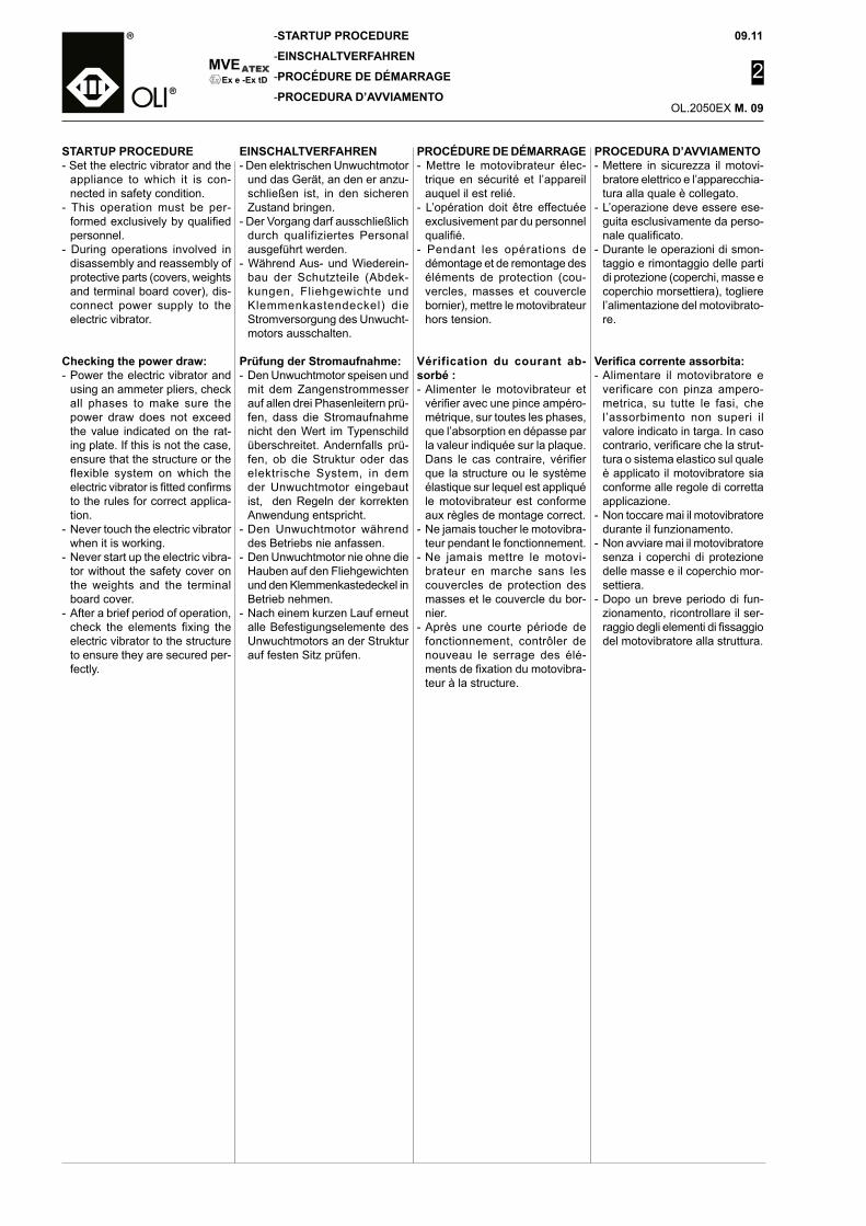
MVE
-
-
-
-
09.11
2
OL.2050EX M.
Ex e -Ex tD
STARTUP PROCEDURE
EINSCHALTVERFAHREN
PROCÉDURE DE DÉMARRAGE
PROCEDURA D’AVVIAMENTO
PROCEDURA D’AVVIAMENTO- Mettere in sicurezza il motovi-
bratore elettrico e l’apparecchia-tura alla quale è collegato.
- L’operazione deve essere ese-guita esclusivamente da perso-nale qualificato.
- Durante le operazioni di smon-taggio e rimontaggio delle parti di protezione (coperchi, masse e coperchio morsettiera), togliere l’alimentazione del motovibrato-re.
Verifica corrente assorbita:- Alimentare il motovibratore e
verificare con pinza ampero-metrica, su tutte le fasi, che l’assorbimento non superi il valore indicato in targa. In caso contrario, verificare che la strut-tura o sistema elastico sul quale è applicato il motovibratore sia conforme alle regole di corretta applicazione.
- Non toccare mai il motovibratore durante il funzionamento.
- Non avviare mai il motovibratore senza i coperchi di protezione delle masse e il coperchio mor-settiera.
- Dopo un breve periodo di fun-zionamento, ricontrollare il ser-raggio degli elementi di fissaggio del motovibratore alla struttura.
STARTUP PROCEDURE- Set the electric vibrator and the
appliance to which it is con-nected in safety condition.
- This operation must be per-formed exclusively by qualified personnel.
- During operations involved in disassembly and reassembly of protective parts (covers, weights and terminal board cover), dis-connect power supply to the electric vibrator.
Checking the power draw:- Power the electric vibrator and
using an ammeter pliers, check all phases to make sure the power draw does not exceed the value indicated on the rat-ing plate. If this is not the case, ensure that the structure or the flexible system on which the electric vibrator is fitted confirms to the rules for correct applica-tion.
- Never touch the electric vibrator when it is working.
- Never start up the electric vibra-tor without the safety cover on the weights and the terminal board cover.
- After a brief period of operation, check the elements fixing the electric vibrator to the structure to ensure they are secured per-fectly.
EINSCHALTVERFAHREN- Den elektrischen Unwuchtmotor
und das Gerät, an den er anzu-schließen ist, in den sicheren Zustand bringen.
- Der Vorgang darf ausschließlich durch qualifiziertes Personal ausgeführt werden.
- Während Aus- und Wiederein-bau der Schutzteile (Abdek-kungen, Fliehgewichte und Klemmenkastendeckel) die Stromversorgung des Unwucht-motors ausschalten.
Prüfung der Stromaufnahme:- Den Unwuchtmotor speisen und
mit dem Zangenstrommesser auf allen drei Phasenleitern prü-fen, dass die Stromaufnahme nicht den Wert im Typenschild überschreitet. Andernfalls prü-fen, ob die Struktur oder das elektrische System, in dem der Unwuchtmotor eingebaut ist, den Regeln der korrekten Anwendung entspricht.
- Den Unwuchtmotor während des Betriebs nie anfassen.
- Den Unwuchtmotor nie ohne die Hauben auf den Fliehgewichten und den Klemmenkastedeckel in Betrieb nehmen.
- Nach einem kurzen Lauf erneut alle Befestigungselemente des Unwuchtmotors an der Struktur auf festen Sitz prüfen.
PROCÉDURE DE DÉMARRAGE- Mettre le motovibrateur élec-
trique en sécurité et l’appareil auquel il est relié.
- L’opération doit être effectuée exclusivement par du personnel qualifié.
- Pendant les opérations de démontage et de remontage des éléments de protection (cou-vercles, masses et couvercle bornier), mettre le motovibrateur hors tension.
Vérification du courant ab-sorbé :- Alimenter le motovibrateur et
vérifier avec une pince ampéro-métrique, sur toutes les phases, que l’absorption en dépasse par la valeur indiquée sur la plaque. Dans le cas contraire, vérifier que la structure ou le système élastique sur lequel est appliqué le motovibrateur est conforme aux règles de montage correct.
- Ne jamais toucher le motovibra-teur pendant le fonctionnement.
- Ne jamais mettre le motovi-brateur en marche sans les couvercles de protection des masses et le couvercle du bor-nier.
- Après une courte période de fonctionnement, contrôler de nouveau le serrage des élé-ments de fixation du motovibra-teur à la structure.
09
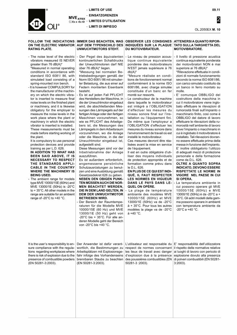
09.11
2
OL.2050EX M.
MVE
-
-
-
-Ex e -Ex tD
ATTENERSI A QUANTO RIPOR-TATO SULLA TARGHETTA DEL MOTOVIBRATORE.
- Il livello di pressione acustica continua equivalente ponderata dei motovibratori NON è mai superiore ai 76 dB(A)*
*Rilevazione effettuata in condi-zioni di normale funzionamento secondo la norma ISO 6081/86, con carico simulato costituito da un banco in ferro montato su molle.
- E’ comunque OBBLIGO del costruttore della macchina in cui il motovibratore viene inglo-bato effettuare le rilevazioni di rumorosità finali sull’impianto o macchinario finito, così come è OBBLIGO del datore di lavoro effettuare le rilevazioni della ru-morosità nell’ambiente di lavoro dove l’impianto o macchinario in cui è inglobato il motovibratore è installato. Tali rilevazioni dovran-no essere effettuate prima della messa in funzione dell’impianto. E’ inoltre obbligatorio l’utilizzo di adeguati mezzi di protezione personale e della formazione come da D.L. 626.
OLTRE A QUANTO SOPRA INDICATO, DEVONO ESSERE RISPETTATE LE NORME IN VIGORE NEL PAESE IN CUI SI OPERA.
- La temperatura ambiente in cui possono operare gli MVE 10000/15E (60Hz) e MVE 13000/1E (50Hz) è da -20°C a + 35°C. Gli aòtri modelli della gam-ma possono operare in ambienti con temperatura ambiente da -20°C a +40 °C.
E’ responsabilità dell’utilizzatore il rispetto delle normative relative ai luoghi di lavoro con pericolo di esplosione dovuto alla presenza di polveri combustibili (EN 50281-3:2003).
LIMITS OF USE
EINSATZGRENZEN
LIMITES D’UTILISATION
LIMITI DI IMPIEGO
FOLLOW THE INDICATIONS ON THE ELECTRIC VIBRATOR RATING PLATE.
- The noise level of the electric vibrators measured IS NEVER greater than 76 dB(A)*
*Measured in normal operating conditions in accordance with standard ISO 6081/ 86, with simulated load consisting of a spring-mounted iron bench.
- It is however COMPULSORY for the manufacturer of the machin-ery on which the electric vibra-tor is inserted to measure final noise levels on the finished plant or machinery, and it is likewise obligatory for the employer to measure the noise levels in the work place where the plant or machinery in which the electric vibrator is inserted is installed.
These measurements must be made before starting working of the plant.
It is compulsory to use personal protection devices and provide training as per L.D. 626.
IN ADDITION TO WHAT HAS BEEN SAID ABOVE, IT IS NECESSARY TO RESPECT THE STANDARDS APPLI-CABLE IN THE COUNTRY WHERE THE MACHINERY IS BEING USED.
- The ambient range for models type MVE 10000/15E (60Hz) and MVE 13000/1E (50Hz) is -20°C to + 35°C. All other models in the range are suitable for an ambient range of -20°C to +40 °C.
It is the user’s responsibility to en-sure compliance with the regula-tions regarding workplaces where there is risk of explosion due to the presence of combustible powders (EN 50281-3:2003).
IMMER DAS BEACHTEN, WAS AUF DEM TYPENSCHILD DES UNWUCHTMOTORS STEHT.
- Der Pegel des äquivalenten kontinuierlichen Schalldrucks der Unwuchtmotoren darf NIE über 76 dB(A)* liegen.
*Messung bei normalen Be-triebsbedingungen gemäß der Norm ISO 6081/ 86 mit simulier-ter Belastung, die aus einer auf Federn montierten Eisenbank besteht.
- Es ist auf jeden Fall PFLICHT des Herstellers der Maschine, in die der Unwuchtmotor eingebaut wird, die abschließenden Mes-sungen des Lärmpegels auf der fertigen Anlage oder den fertigen Maschinen vorzunehmen, so wie es PFLICHT des Arbeitge-bers ist, die Messungen des Lärmpegels in dem Arbeitsraum vorzunehmen, wo die Anlage oder die Maschine, in die der Unwuchtmotor eingebaut ist, aufgestellt sind.
Diese Messungen sind vor der Inbetriebnahme der Anlage auszuführen.
Es ist außerdem erforderlich, angemessene persönl iche Schutzausrüstungen zu benut-zen und eine Ausbildung gemäß Gesetzesdekret 626 zu geben.
NEBEN DEN OBIGEN PUNK-TEN MÜSSEN AUCH DIE NOR-MEN BEACHTET WERDEN, DIE IN DEM LAND GELTEN, IN DEM DER UNWUCHTMOTOR BETRIEBEN WIRD.
- Der Bereich der Raumtempe-raturen für die Modelle MVE 10000/15E (60 Hz) und MVE 13000/1E (50 Hz) geht von -20°C bis + 35°C. Für alle an-deren Modelle geht der Bereich von -20°C bis +40 °C.
Der Anwender ist dafür verant-wortlich, die Bestimmungen zu Arbeitsplätzen mit Explosionsge-fahr infolge des Vorhandenseins brennbaren Staubs zu beachten (EN 50281-3:2003).
OBSERVER LES CONSIGNES INDIQUÉES SUR LA PLAQUE DU MOTOVIBRATEUR.
- Le niveau de pression acous-tique continue équivalente pondérée des motovibrateurs N’EST jamais supérieure à 76 db(A)*
*Mesure réalisée en condi-tions de fonctionnement normal conformément à la norme ISO 6081/86, avec charge simulée constituée d’un banc en fer monté sur ressorts.
- Le constructeur de la machine dans laquelle le motovibrateur est intégré a l’OBLIGATION d’effectuer les mesures du niveau sonore final sur l’ins-tallation ou l’équipement fini. De même que l’employeur a l’OBLIGATION d’effectuer les mesures du niveau sonore dans l’environnement de travail où est installé le motovibrateur.
Ces mesures devront être réa-lisées avant la mise en service de l’équipement.
Il est en outre obligatoire d’uti-liser des moyens individuels de protection appropriés et de formation comme prévu dans le D.L. 626.
EN PLUS DE CE QUI EST INDI-QUÉ, IL FAUT RESPECTER LES NORMES EN VIGUEUR DANS LE PAYS DANS LE-QUEL ON OPÈRE.
- La plage de température ambiante des modèles MVE 10000/15E (60Hz) et MVE 13000/1E (50Hz) va de -20°C à + 35°C. Pour tous les autres modèles la plage va de -20°C à +40 °C.
L’utilisateur est responsable du respect de normes concernant les lieux de travail avec danger d’explosion due à la présence des poussières combustibles (EN 50281-3 :2003).
10
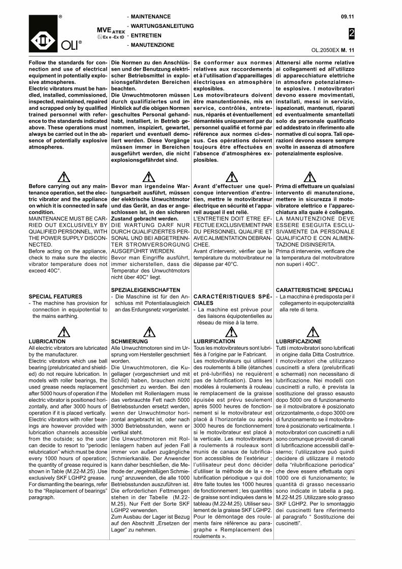
MVE
-
-
-
-
09.11
2
OL.2050EX M.
Ex e -Ex tD
Attenersi alle norme relative ai collegamenti ed all’utilizzo di apparecchiature elettriche in atmosfere potenzialmen-te esplosive. I motovibratori devono essere movimentati, installati, messi in servizio, ispezionati, mantenuti, riparati ed eventualmente smantellati solo da personale qualificato ed addestrato in riferimento alle normative di cui sopra. Tali ope-razioni devono essere sempre svolte in assenza di atmosfere potenzialmente esplosive.
MAINTENANCE
WARTUNGSANLEITUNG
ENTRETIEN
MANUTENZIONE
Prima di effettuare un qualsiasi intervento di manutenzione, mettere in sicurezza il moto-vibratore elettrico e l’apparec-chiatura alla quale è collegato.LA MANUTENZIONE DEVE ESSERE ESEGUITA ESCLU-SIVAMENTE DA PERSONALE QUALIFICATO E CON ALIMEN-TAZIONE DISINSERITA.Prima di intervenire, verificare che la temperatura del motovibratore non superi i 40C°.
CARATTERISTICHE SPECIALI - La macchina è predisposta per il
collegamento in equipotenzialità alla rete di terra.
LUBRIFICAZIONE Tutti i motovibratori sono lubrificati in origine dalla Ditta Costruttrice. I motovibratori che utilizzano cuscinetti a sfera (prelubrificati e schermati) non necessitano di lubrificazione. Nei modelli con cuscinetti a rullo, è prevista la sostituzione del grasso esausto dopo 5000 ore di funzionamento se il motovibratore è posizionato orizzontalmente, o dopo 3000 ore di funzionamento se il motovibra-tore è posizionato verticalmente. I motovibratori con cuscinetti a rulli sono comunque provvisti di canali di lubrificazione accessibili dall’e-sterno; l’utilizzatore può quindi decidere di utilizzare il metodo della “rilubrificazione periodica” che deve essere effettuata ogni 1000 ore di funzionamento; le quantità di grasso necessario sono indicate in tabella a pag. M.22-M.25 .Utilizzare solo grasso SKF LGHP2. Per lo smontaggio dei cuscinetti fare riferimento al paragrafo “ Sostituzione dei cuscinetti”.
Follow the standards for con-nection and use of electrical equipment in potentially explo-sive atmospheres. Electric vibrators must be han-dled, installed, commissioned, inspected, maintained, repaired and scrapped only by qualified trained personnel with refer-ence to the standards indicated above. These operations must always be carried out in the ab-sence of potentially explosive atmospheres.
Die Normen zu den Anschlüs-sen und der Benutzung elektri-scher Betriebsmittel in explo-sionsgefährdeten Bereichen beachten. Die Unwuchtmotoren müssen durch qualifiziertes und im Hinblick auf die obigen Normen geschultes Personal gehand-habt, installiert, in Betrieb ge-nommen, inspiziert, gewartet, repariert und eventuell demo-liert werden. Diese Vorgänge müssen immer in Bereichen ausgeführt werden, die nicht explosionsgefährdet sind.
Se conformer aux normes relatives aux raccordements et à l’utilisation d’appareillages électriques en atmosphère explosibles. Les motovibrateurs doivent être manutentionnés, mis en service, contrôlés, entrete-nus, réparés et éventuellement démantelés uniquement par du personnel qualifié et formé par référence aux normes ci-des-sus. Ces opérations doivent toujours être effectuées en l’absence d’atmosphères ex-plosibles.
Avant d’effectuer une quel-conque intervention d’entre-tien, mettre le motovibrateur électrique en sécurité et l’appa-reil auquel il est relié.L’ENTRETIEN DOIT ETRE EF-FECTUE EXCLUSIVEMENT PAR DU PERSONNEL QUALIFIE ET AVEC ALIMENTATION DEBRAN-CHEE.Avant d’intervenir, vérifier que la température du motovibrateur ne dépasse par 40°C.
CARACTÉRISTIQUES SPÉ-CIALES- La machine est prévue pour
des liaisons équipotentielles au réseau de mise à la terre.
Bevor man irgendeine War-tungsarbeit ausführt, müssen der elektrische Unwuchtmotor und das Gerät, an das er ange-schlossen ist, in den sicheren Zustand gebracht werden.DIE WARTUNG DARF NUR DURCH QUALIFIZIERTES PER-SONAL UND BEI ABGETRENN-TER STROMVERSORGUNG AUSGEFÜHRT WERDEN.Bevor man Eingriffe ausführt, immer sicherstellen, dass die Temperatur des Unwuchtmotors nicht über 40C° liegt.
SPEZIALEIGENSCHAFTEN- Die Maschine ist für den An-
schluss mit Potentialausgleich an das Erdungsnetz vorgerüstet.
Before carrying out any main-tenance operation, set the elec-tric vibrator and the appliance on which it is connected in safe condition.MAINTENANCE MUST BE CAR-RIED OUT EXCLUSIVELY BY QUALIFIED PERSONNEL, WITH THE POWER SUPPLY DISCON-NECTED.Before acting on the appliance, check to make sure the electric vibrator temperature does not exceed 40C°.
SPECIAL FEATURES- The machine has provision for
connection in equipotential to the mains earthing.
LUBRIFICATIONTous les motovibrateurs sont lubri-fiés à l’origine par le Fabricant.Les motovibrateurs qui utilisent des roulements à bille (étanches et pré-lubrifiés) ne requièrent pas de lubrification). Dans les modèles à roulements à rouleau le remplacement de la graisse épuisée est prévu seulement après 5000 heures de fonction-nement si le motovibrateur est placé à l’horizontale ou après 3000 heures de fonctionnement si le motovibrateur est placé à la verticale. Les motovibrateurs à roulements à rouleaux sont munis de canaux de lubrifica-tion accessibles de l’extérieur ; l’utilisateur peut donc décider d’utiliser la méthode de la « re-lubrification périodique » qui doit être faite toutes les 1000 heures de fonctionnement ; les quantités de graisse sont indiquées dans le tableau (M.22-M.25). Utiliser seu-lement de la graisse SKF LGHP2. Pour le démontage des roule-ments faire référence au para-graphe « Remplacement des roulements ».
SCHMIERUNGAlle Unwuchtmotoren sind im Ur-sprung vom Hersteller geschmiert worden.Die Unwuchtmotoren, die Ku-gellager (vorgeschmiert und mit Schild) haben, brauchen nicht geschmiert zu werden. Bei den Modellen mit Rollenlagern muss das verbrauchte Fett nach 5000 Betriebsstunden ersetzt werden, wenn der Unwuchtmotor hori-zontal angebracht ist, oder nach 3000 Betriebsstunden, wenn er vertikal steht.Die Unwuchtmotoren mit Rol-lenlagern haben auf jeden Fall immer von außen zugängliche Schmierkanäle. Der Anwender kann daher beschließen, die Me-thode der „regelmäßigen Schmie-rung” anzuwenden, die alle 1000 Betriebsstunden auszuführen ist. Die erforderlichen Fettmengen stehen in der Tabelle (M.22-M.25). Nur Fett der Sorte SKF LGHP2 verwenden. Zum Ausbau der Lager ist Bezug auf den Abschnitt „Ersetzen der Lager” zu nehmen.
LUBRICATIONAll electric vibrators are lubricated by the manufacturer.Electric vibrators which use ball bearing (prelubricated and shield-ed) do not require lubrication. In models with roller bearings, the used grease needs replacement after 5000 hours of operation if the electric vibrator is positioned hori-zontally, and after 3000 hours of operation if it is placed vertically.Electric vibrators with roller bear-ings are however provided with lubrication channels accessible from the outside; so the user can decide to resort to “periodic relubrication” which must be done every 1000 hours of operation; the quantity of grease required is shown in Table (M.22-M.25) .Use exclusively SKF LGHP2 grease. For dismantling the bearings, refer to the “Replacement of bearings” paragraph.
11
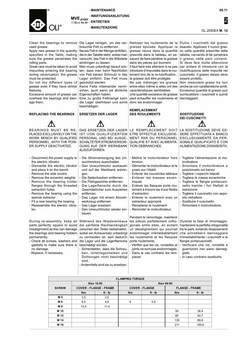
09.11
2
OL.2050EX M.
MVE
-
-
-
-Ex e -Ex tD
MAINTENANCE
WARTUNGSANLEITUNG
ENTRETIEN
MANUTENZIONE
Pulire i cuscinetti dal grasso esausto. Applicare il nuovo gras-so nella quantità prescritta dalla tabella, cercando di far penetrare il grasso nelle parti volventi. Si deve fare molta attenzione per evitare di introdurre con la rilubrificazione delle impurità nel cuscinetto; il grasso stesso deve essere protetto.Non mescolare grassi tra loro anche se con caratteristiche simili. Eccessiva quantità di grasso può surriscaldare i cuscinetti e quindi danneggiarli.
SOSTITUZIONE DEI CUSCINETTI
LA SOSTITUZIONE DEVE ES-SERE EFFETTUATA A BANCO ESCLUSIVAMENTE DA PER-SONALE QUALIFICATO E CON ALIMENTAZIONE DISINSERITA.
- Togliere l’alimentazione al mo-tovibratore
- Smontare il motovibratore e posizionarlo sul banco
- Togliere i coperchi laterali- Togliere le masse eccentriche- Togliere le flangie portacusci-
netto tramite i fori filettati di estrazione
- Togliere il cuscinetto con appo-sito estrattore
- Sostituire il cuscinetto- Rimontare il motovibratore.
Durante la fase di rimontaggio, mantenere la perfetta ortogonalità tra le parti, evitando disassamenti che potrebbero danneggiare irrimediabilmente i cuscinetti e le flangie portacuscinetti. - Verificare che viti, rondelle e
guarnizioni non siano danneg-giate.
- In caso contrario sostituirle.
Clean the bearings to remove used grease. Apply new grease in the quantity specified in the Table, making sure the grease penetrates the rolling parts.Great care must be taken to avoid impurities entering the bearing during relubrication; the grease must be protected.Do not mix different types of grease even if they have similar features.Excessive amount of grease can overheat the bearings and dam-age them.
REPLACING THE BEARINGS
Die Lager reinigen, um das ver-brauchte Fett zu entfernen. Neues Fett in der Menge einfüllen, die in der Tabelle steht, wobei man versucht, das Fett in die Wälzteile eindringen zu lassen.Man muss unbedingt darauf ach-ten, dass man beim Nachfüllen von Fett keinen Schmutz in das Lager einführt. Das Fett muss geschützt werden.Keine Fette miteinander vermi-schen, auch wenn sie ähnliche Eigenschaften haben.Eine zu große Fettmenge kann die Lager überhitzen und somit beschädigen.
ERSETZEN DER LAGER
Nettoyer les roulements de la graisse épuisée. Appliquer la graisse neuve dans la quantité prescrite dans le tableau, en es-sayant de faire pénétrer la graisse dans les pièces qui tournent.Il faut faire très attention à ne pas introduire d’impuretés dans le rou-lement lors de la re-lubrification ; la graisse doit être protégée.Ne pas mélanger les graisse entre-elles même si elles ont des caractéristiques semblables.Une quantité excessive de graisse peut échauffer les roulements et donc les endommager.
REMPLACEMENT DES ROULEMENTS
LE REMPLACEMENT DOIT ETRE EFFECTUE EXCLUSIVE-MENT PAR DU PERSONNEL QUALIFIE ET AVEC ALIMENTA-TION DEBRANCHEE.
- Mettre le motovibrateur hors tension
- Démonter le motovibrateur et le poser sur l’établi
- Enlever les couvercles latéraux- Enlever les masses excen-
triques- Enlever les flasques porte rou-
lement à travers les trous filetés d’extraction
- Enlever le roulement avec un extracteur approprié
- Remplacer le roulement- Remonter le motovibrateur.
Pendant le remontage, maintenir les pièces parfaitement ortho-gonale entre elles, en évitant un désalignement qui pourrait endommager irrémédiablement les roulements et les flasques porte roulements. - Vérifier que les vis, rondelles et
joints ne sont pas endommagés.- Dans le cas contraire les rem-
placer.
DAS ERSETZEN DER LAGER IST VON QUALIFIZIERTEM PERSONAL UND BEI AUSGE-SCHALTETER STROMVERSOR-GUNG AUF DER WERKBANK AUSZUFÜHREN.
- Die Stromversorgung des Un-wuchtmotors ausschalten.
- Den Unwuchtmotor ausbauen und auf der Werkbank anbrin-gen.
- Die Seitenhauben entfernen.- Die Fliehgewichte entfernen.- Die Lagerflansche durch die
Gewindelöcher zum Ausziehen entfernen.
- Das Lager mit einem Abzieh-werkzeug entfernen.
- Das Lager ersetzen.- Den Unwuchtmotor wieder ein-
bauen.
Während des Wiedereinbaus die perfekte Rechtwinkligkeit zwischen den Teilen beibehalten, wobei ein Achsversatz unbedingt zu vermeiden ist, weil dadurch die Lager und die Lagerflansche beschädigt würden. - Sicherstellen, dass die Schrau-
ben, Unterlegscheiben und Dichtungen nicht beschädigt sind.
- Andernfalls sind sie zu ersetzen.
BEARINGS MUST BE RE-PLACED EXCLUSIVELY ON THE WORK BENCH BY QUALIFIED PERSONNEL, WITH THE POW-ER SUPPLY DEACTIVATED.
- Disconnect the power supply to the electric vibrator
- Dismantle the electric vibrator and place it on the bench
- Remove the side covers- Remove the eccentric weights- Remove the bearing holder
flanges through the threaded extraction holes
- Remove the bearing using the special extractor
- Fit a new bearing the bearing- Reassemble the electric vibra-
tor.
During re-assembly, keep all parts perfectly square to avoid misalignment as this can damage the bearings and bearing holders permanently. - Check all screws, washers and
gaskets to make sure there is no damage.
- Replace, if necessary.
CLAMPING TORQUE
SCREWSize 10-50 Size 60-90
COVER - FLANGE - FRAME COVER - FLANGE FLANGE - FRAMENm ft - lb Nm ft - lb Nm ft - lb
M 5 3.5 2.6M 6 6.5 4.8 8 5.9M 8 15.5 11.4
M 10 50 36.9M 12 85 62.7M 14 135 99.6M 16 211 155.6
12
MVE
-
-
-
-
09.11
2
OL.2050EX M.
Ex e -Ex tD
MAINTENANCE: PERIODIC CHECKS
WARTUNG: REGELMÄSSIGE KONTROLLEN
ENTRETIEN: CONTROLES PERIODIQUES
MANUTENZIONE: CONTROLLI PERIODICI
Prima di effettuare un qualsiasi intervento di manutenzione, mettere in sicurezza il moto-vibratore elettrico e l’apparec-chiatura alla quale è collegato.
Prima di ogni turno di lavoro:- A seconda delle condizioni di
funzionamento, rimuovere ac-curatamente gli strati di povere di deposito avendo cura di non provocare nubi aerodisperse. Gli strati di polvere depositata non deve mai superare i 5mm di spessore!
- Controllare che non vi siano rumori anomali dovuti a sfrega-menti o rotture del motovibratore elettrico.
Mensilmente:- Verificare l’integrità della tar-
ghetta, se danneggiata, occorre chiederne una copia al costrut-tore.
- Verificare l’integrità del pitto-grammi, se danneggiati, sosti-tuirli.
- Controllare il serraggio delle viti di fissaggio del motovibratore.
- Controllare l’integrità della cate-na o del cavo di sicurezza.
- Far verificare la continuità verso il circuito di terra da personale specializzato.
PULIZIA
Prima di effettuare un qualsiasi intervento di manutenzione o pulizia sulla macchina assicu-rarsi che questa sia messa in sicurezza.
- Nella rimozione della polvere eventualmente presente sulla motovibratore elettrico aver cura di non disperdere la polvere stessa nell’ambiente circostan-te. Gli strati di polvere depositata non deve mai superare i 5mm di spessore!
- Pulire esclusivamente con l’au-silio di un panno umido
- La frequenza delle operazioni di pulizia dipendono dalla natura del prodotto trattato dall’appa-recchio in cui viene inserito il motovibratore elettrico.
- Non dirigere direttamente getti d’acqua ad alta pressione sul motovibratore elettrico.
Before carrying out any mainte-nance, set the electric vibrator and the appliance on which it is fitted in safe condition.
Before each work shift:- Depending on the operating
conditions, wipe off the layers of dust deposited taking care to avoid throwing up clouds of dust.
The dust layers must never be more than 5mm thick!
- Check for abnormal noise due to rubbing or breakage of the electric vibrator.
Every month:- Check the identification plate
and if it is damaged contact the manufacturer for a copy.
- Check the pictograms and re-place those that are damaged.
- Check to make sure all the fixing screws of the electric vibrator are secured properly.
- Check the condition of the safety cable or rope.
- Have a specialist technician check the continuity to the earth circuit.
CLEANING
Before carrying out any main-tenance or cleaning on the machine, make sure it is set in safe conditions.
- While removing the dust that may be present on the electric vibrator, take care to avoid its dispersal in the surroundings.
Dust deposits must never ex-ceed a thickness of 5mm!
- Use only a damp cloth to remove the dust.
- Frequency of cleaning opera-tions depends on the type of product handled by the appli-ance in which the electric vibra-tor is inserted.
- Do not direct high pressure water jets on the electric vibrator.
Bevor man irgendeine War-tungsarbeit ausführt, den elek-trischen Unwuchtmotor und das Gerät, an das er ange-schlossen ist, in den sicheren Zustand bringen.
Vor jeder Arbeitsschicht:- Je nach den Betriebsbedin-
gungen sorgfältig die Staub-schichten entfernen, die sich abgelagert haben, und darauf achten, dass keine durch die Luft verteilten Staubwolken entstehen.
Die abgelagerten Staubschich-ten dürfen nie dicker als 5 mm sein!
- Sicherstellen, dass keine Stör-geräusche vorliegen, die auf Abrieb oder Brüchen des elektri-schen Unwuchtmotors beruhen.
Monatlich:- Das Typenschild auf Unversehrt-
heit prüfen. Wenn es beschädigt ist, muss eine Kopie beim Her-steller angefordert werden.
- Die Unversehrtheit der Pik-togramme prüfen. Sind sie beschädigt, müssen sie ersetzt werden.
- Die Befestigungsschrauben des Unwuchtmotors auf festen Sitz prüfen.
- Die Sicherheitskette bzw. den Sicherheitsdraht auf Unver-sehrtheit prüfen.
- Den Erdungskreis durch den Fachmann auf Durchgang prü-fen lassen.
REINIGUNG
Vor der Ausführung jeder Rei-nigung oder Wartungsarbeit an der Maschine immer sicherstel-len, dass diese in den sicheren Zustand gebracht worden ist.- Beim Entfernen von Staub,
der sich eventuell auf dem elektrischen Unwuchtmotor abgelagert hat, darauf achten, dass man den Staub nicht in der Luft verteilt.
Die abgelagerten Staubschich-ten dürfen nie dicker als 5 mm sein!
- Zum Reinigen ausschließlich feuchte Tücher verwenden.
- Die Häufigkeit der Reinigungen hängen von der Beschaffenheit des Produkts ab, das von dem Gerät behandelt wird, in das der elektrische Unwuchtmotor eingebaut wird.
- Kein unter hohem Druck stehen-den Wasser direkt auf den elek-trischen Unwuchtmotor spritzen.
Avant d’effectuer une quel-conque intervention d’entre-tien, mettre le motovibrateur électrique en sécurité et l’appa-reil auquel il est relié.
Avant chaque tour de travail:- Suivant les conditions de fonc-
tionnement, éliminer soigneuse-ment les couches de poussière déposée en faisant attention à ne pas provoquer de nuages dispersés dans l’air.
Les couches de poussière dépo-sée ne doivent jamais dépasser 5 mm d’épaisseur !
- Contrôler qu’il n’y a pas de bruits anormaux dus à des frottements ou ruptures du motovibrateur électrique.
Tous les mois :- Vérifier l’intégrité de la plaque,
si elle est endommagée il faut en demander une copie au constructeur.
- Vérifier l’intégrité des picto-grammes, s’ils sont endomma-gés les remplacer.
- Contrôler le serrage des vis de fixation du motovibrateur.
- Contrôler l’intégrité de la chaîne ou du câble de sécurité.
- Faire vérifier la continuité vers le circuit de terre par du personnel spécialisé.
NETTOYAGE
Avant d’effectuer une quel-conque intervention d’entretien ou de nettoyage sur la machine, s’assurer qu’elle a été mise en sécurité.
- Lors de l’élimination de la pous-sière éventuellement présente sur le motovibrateur électrique, prendre soin de ne pas la disper-ser dans l’environnement.
Les couches de poussière dépo-sée ne doivent jamais dépasser 5 mm d’épaisseur !
- Nettoyer exclusivement à l’aide d’un chiffon humide
- La fréquence des opérations de nettoyage dépend de la nature du produit traité par l’appareil dans lequel le motovibrateur électrique est inséré.
- Ne pas diriger directement le jet d’eau à haute pression sur le motovibrateur électrique.
13

09.11
2
OL.2050EX M.
MVE
-
-
-
-Ex e -Ex tD
RESIDUAL RISKS
RESTRISIKEN
RISQUES RESIDUELS
RISCHI RESIDUI
E’ OBBLIGATORIO USARE I GUANTI
E’ OBBLIGATORIO USARE LE CALZATUREDI SICUREZZA
PORT DE GANTSOBLIGATOIRE
CHASSURES DE SÉCURITÉ OBLIGATOIRES
DIE BENUTZUNG VONHANDSCHUHE ISTVORGESCHRIEBEN
DIE BENUTZUNG VON SICHERHEITS SCHUHWERK IST VORGESCHRIEBEN
GLOVE ARECOMPULSORY
SAFETY FOOTWEAR ARECOMPULSORY
E’ OBBLIGATORIO USARE LAMASCHERA
DIE BENUTZUNG DER MASKE IST VORGESCHRIEBEN
MASQUEOBLIGATOIRE
MASK ISCOMPULSORY
L’installatore, in base all’utilizzo del motovibratore elettrico, deve informare gli operatori, tramite ap-positi segnali, in merito ai seguenti rischi residui:
1.Pericoli di natura meccanicaPer le attività di manutenzione è fatto obbligo all’operatore di impiegare sempre i dispositivi di protezione individuale. Apposite targhe monitorie in prossimità della macchina indicano quali di-spositivi di protezione individuale si rendono obbligatori:
2.Presenza di polveri potenzialmente pericolose Nel caso di interventi sia ordinari che straordinari di manutenzione l’operatore deve dotarsi di idonei dispositivi di protezione individua-le ed in particolare utilizzare ma-schere a protezione delle vie re-spiratorie di classe idonea in base al tipo di polvere trattata nonché di guanti o indumenti. Per maggiori dettagli si deve far riferimento alla scheda di sicurezza prodotto trattato dall’apparecchiatura nel quale il motovibratore è inserito.
2.Presence of potentially haz-ardous powdersFor carrying out routine and extraordinary maintenance op-erations, the operators must use special personal protection devices, and a mask, in particular, to protect the respiratory tract belonging to a Class suitable for the type of powder handled, in addition to protective gloves or clothing. For more details, consult the safe-ty chart of the powder handled by the appliance in which the electric vibrator is inserted.
Depending on the use of the elec-tric vibrator, it is necessary to use special signals to warn the opera-tors of the following residual risks:
1.Mechanical hazardsFor maintenance operations, the operator must always use per-sonal protection devices. Special warning notices near the machine indicate the personal protection devices that must be used compulsorily:
Je nach der Benutzung des elek-trischen Unwuchtmotors muss der Installateur den Anwender mittels geeigneter Signalschilder über die folgenden Restrisiken unterrichten:
1. Gefahren mechanischer ArtFür die Ausführung von War-tungsarbeiten muss der Arbeit-nehmer immer die persönlichen Schutzausrüstungen benutzen. Besondere Hinweisschilder in der Nähe der Maschine eben an, welche persönlichen Schutzaus-rüstungen obligatorisch zu be-nutzen sind:
2. Vorhandensein explosions-gefährdeten StaubsBei der Ausführung von lau-fenden oder außerordentlichen Wartungsarbeiten muss der Arbeitnehmer geeignete per-sönliche Schutzausrüstungen benutzen, insbesondere Masken zum Schutz der Atemwege der geeigneten Klasse aufgrund der behandelten Stäube, und Schutzkleidung, sowie Schutz-handschuhe. Für eingehendere Angaben ist Be-zug auf das Sicherheitsdatenblatt des Produkts zu nehmen, das in der Anlage behandelt wird, in die der Unwuchtmotor eingebaut worden ist.
En fonction de l’utilisation du motovibrateur DLP, l’installateur doit informer les opérateurs des risques résiduels par des signaux appropriés :
1. Danger de nature mécaniquePour les activités d’entretien, l’opérateur a l’obligation de por-ter toujours les équipements de protection individuelle. Des panneaux d’avertissement spécifiques, placés à proximité de la machine, doivent indiquer quels sont les équipements de protection individuelle qui se rendent obligatoires :
2. Présence de poudres poten-tiellement dangereusesEn cas d’interventions ordinaires ou extraordinaires d’entretien, l’opérateur doit se doter d’équipe-ments de protection individuelle et notamment utiliser des masques de protection des voies respira-toires de classe appropriée en fonction du type de poudre trai-tée, ainsi que des gants ou des vêtements.
14
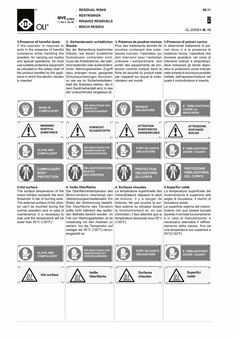
MVE
-
-
-
-
09.11
2
OL.2050EX M.
Ex e -Ex tD
ATTENZIONESOSTANZE NOCIVE
VORSICHT: SCHADSTOFFE
WARNINGHURTFULSUBSTANCE
ATTENTIONSUBSTANCESDANGEREUSES
3.Presenza di polveri nociveIn determinati trattamenti di pol-veri dove vi è la presenza di sostanze nocive, l’operatore che dovesse accedere, nel corso di interventi ordinari e straordinari, deve indossare gli idonei dispo-sitivi di protezione come indicato nella scheda di sicurezza prodotto trattato dall’apparecchiatura nel quale il motovibratore è inserito.
E’ OBBLIGATORIO USARE LAMASCHERA
DIE BENUTZUNG DER MASKE IST VORGESCHRIEBEN
MASQUEOBLIGATOIRE
MASK ISCOMPULSORY
RESIDUAL RISKS
RESTRISIKEN
RISQUES RESIDUELS
RISCHI RESIDUI
E’ OBBLIGATORIO USARE I GUANTI
PORT DE GANTSOBLIGATOIRE
DIE BENUTZUNG VONHANDSCHUHE ISTVORGESCHRIEBEN
GLOVE ARECOMPULSORY
PROTEZIONEOBBLIGATORIADEL CORPO
3.Presence of harmful dustsIf the operator is required to work in the presence of harmful substance while handling the powders, for carrying out routine and special operations, he must use suitable protective equipment as indicated in the safety chart of the product handled by the appli-ance in which the electric vibrator is inserted.
COMPULSORY BODY PROTECTION
OBLIGATORISCHER SCHUTZ DES KÖRPERS
PROTECTIONOBLIGATOIREDU CORPS
3. Vorhandensein schädlichen StaubsBei der Behandlung bestimmter Stäube, bei denen schädliche Substanzen vorhanden sind, muss der Arbeitnehmer, der wäh-rend laufender oder außerordent-licher Wartungsarbeiten Zugriff dazu erlangen muss, geeignete Schutzausrüstungen benutzen, so wie sie im Sicherheitsdaten-blatt der Substanz stehen, die in dem Gerät behandelt wird, in das der Unwuchtmotor eingebaut ist.
3. Présence de poudres nocivesPour des traitements donnés de poudres contenant des subs-tances nocives, l’opérateur qui doit intervenir pour l’entretien ordinaire / extraordinaire, doit porter des équipements de pro-tection comme indiqué dans la fiche de sécurité du produit traité par l’appareil sur lequel le moto-vibrateur est monté.
15
4.Superfici caldeLa temperatura superficiale del motovibratore è superiore alla soglia di bruciatura. Il rischio di bruciatura esiste.La superficie esterna del motovi-bratore non può essere toccata durante il normale funzionamento e in caso di manutenzione; è necessario attendere il raffred-damento della stessa, fino ad una temperatura non superiore a 55°C(130°F)
4.Hot surfaceThe surface temperature of the motor-vibrator exceeds the burn threshold. A risk of burning exist. The external surface of the vibra-tor can’t be touched during the normal operation and, in case of maintenance, it is necessary to wait until the temperature will be lower than 55°C (130°F)”.
4. heiße OberflächeDie Oberflächentemperatur des Motorvibrators übersteigt den Verbrennungsschwellenwert. Ein Risiko der Verbrennung besteht. Die Oberfläche des Vibrators sollte nicht während des laufen-den Betriebs berührt werden. Im Fall von Wartungsarbeiten ist es notwendig mit den Arbeiten zu warten, bis die Temperatur auf webiger als 55°C (130°F) herun-tergekühlt ist.
4. Surfaces chaudesLa température superficielle des motovibrateurs dépasse le seuil de brûlure. Il y a danger de brûlures. Ne pas toucher la sur-face externe du vibrateur durant le fonctionnement et, en cas d'entretien, il faut attendre que la température descende sous 55°c (130°F).
heißeOberflächeHot surface
Surfaces chaudes
E’ OBBLIGATORIO USARE I GUANTI
PORT DE GANTSOBLIGATOIRE
DIE BENUTZUNG VONHANDSCHUHE ISTVORGESCHRIEBEN
GLOVE ARECOMPULSORY
Superfici calde
09.11
2
OL.2050EX M.
MVE
-
-
-
-Ex e -Ex tD
SCRAPPING THE MACHINE / RETURNING
VERSCHROTTUNG DES GERÄTS / RÜCKGABE
DEMANTELEMENT DE LA MACHINE / RESTITUTION
ROTTAMAZIONE MACCHINA / RESO MACCHINA
ROTTAMAZIONE MACCHINA
- Prima di procedere alla rottama-zione del motovibratore elettrico provvedere alla sua completa pulizia ed allo smaltimento delle polveri residue in accordo con le indicazioni della scheda di sicurezza.
- Lo smantellamento della mac-china è da effettuarsi in zona classificata sicura.
- Gli operatori addetti allo smal-timento devono indossare di-spositivi di protezione personale adeguati.
- Il motovibratore elettrico deve essere demolito in modo tale da non essere più riutilizzato come unità completa, ne sia possibile riutilizzare una o più delle sue parti.
Nel caso di smaltimento del grasso esausto del motovibratore, è obbligatorio attenersi alla legi-slazione vigente nel paese in cui si opera. In caso di rottamazione a fine vita della macchina, avere cura di smontare le varie parti in materiale plastico (guarnizioni) e destinarle agli appositi centri di raccolta. Le restanti parti sono da destinare al recupero dei materiali ferrosi.
RESO MACCHINA
In caso di reso della macchina, se si è conservato l’imballo, reinserirla nello stesso, altrimenti riporla in una scatola, cercando di proteggerla al meglio da eventuali urti derivanti dal trasporto. In ogni caso assicurarsi che la macchina non abbia residui di materiale.
SCRAPPING THE MACHINE
- Before scrapping the electric vibrator clean it thoroughly and dispose off the residual dust in accordance with the indications in the material safety chart.
- Dismantling operations must be carried out in an area classified as safe.
- The operators involved in the scrapping operations must use suitable personal protection devices.
- The electric vibrator must be dismantled in such a way that it cannot be used as a complete unit, and it must be impossible to reuse the parts.
To dispose off the used grease from the electric vibrator, it is com-pulsory to abide by the legislation applicable in the country of use. For scrapping the machine at the end of its life, separate the parts made of plastic (gaskets) and send these to special collection centres.The remaining parts must be sent to the scrap yard.
RETURNING THE MACHINE
If the machine is to be returned, replace it in the original packing if it has been retained, or pack it in a box, protecting it as far as pos-sible from impact during transport. In any case, make sure there is no material residue inside the machine.
VERSCHROTTUNG DER MASCHINE
- Bevor man den elektrischen Unwuchtmotor verschrottet, ist er vollkommen zu reinigen, um den restlichen, darin vorhande-nen Staub so zu entsorgen, wie es im entsprechenden Sicher-heitsdatenblatt vorgesehen ist.
- Die Zerlegung der Maschine ist in einer als sicher eingestuften Zone vorzunehmen.
- Die mit der Entsorgung be-auftragten Arbeitnehmer müs-sen passende persönliche Schutzausrüstungen tragen.
- Der elektrische Unwuchtmotor muss so demoliert werden, dass er nicht als komplette Einheit wiederverwendet werden kann, und dass es auch nicht möglich ist, eines oder mehrere seiner Teile wiederzuverwenden.
Bei der Entsorgung des Altfetts des Unwuchtmotors ist es vor-geschrieben, die Gesetze des Landes zu beachten, indem man arbeitet. Bei der Verschrottung der Maschine am Ende der Le-benszeit der Maschine die ver-schiedenen Teile aus Kunststoff (Dichtungen) ausbauen und den entsprechenden Sammelstellen zuführen.Die restlichen Teile sind als Ei-senschrott wiederzuverwenden.
RETOURNIERUNG DER MASCHINE
Bei der Retournierung der Ma-schine ist diese, falls man die Originalverpackung aufbewahrt hat, wieder darin einzupacken. Ansonsten stellt man sie in einen Karton und versucht, sie so gut wie möglich vor etwaigen Stö-ßen während des Transports zu schützen. Auf jeden Fall sicherstellen, dass die Maschine keine Materialreste mehr enthält.
DÉMANTÈLEMENT DE LA MACHINE
- Avant mettre l’émotteur à la décharge le nettoyer complète-ment et éliminer les poussières restantes conformément aux indications fournies par la fiche de sécurité.
- Le démantèlement de la ma-chine doit être effectué dans une zone classée sûre.
- Les opérateurs préposés à la mise à la décharge doivent porter des équipements de pro-tection individuelle appropriés.
- Le motovibrateur électrique doit être mis à la décharge de manière à ne plus être utilisé comme unité complète, et qu’il ne soit pas possible de réutiliser une ou plusieurs de ses parties.
Pour éliminer la graisse épuisée du motovibrateur, il est obligatoire de se conformer à la législation en vigueur dans le pays où opère la machine. En cas de mise à décharge ou démolition à la fin de la vie de la machine, prendre soin de démonter les pièces en matière plastique (joints) et les destiner aux déchetteries spé-cialisées.Les parties restantes seront desti-nées au recyclage des matériaux ferreux.
RESTITUTION MACHINE
En cas de restitution de la ma-chine, si l’emballage a été conser-vé, la remettre dans celui-ci, sinon la mettre dans un carton, en essayant de la protéger le plus possible contre les chocs dérivant du transport. Dans tous les cas s’assurer que la machine ne contient pas de résidus de matière.
16
MVE
-
-
-
-
09.11
2
OL.2050EX M.
Ex e -Ex tD
DECLARATION OF CONFORMITY
KONFORMITÄTSERKLÄRUNG
DECLARATION DE CONFORMITE
DICHIARAZIONE DI CONFORMITA’
L’apparecchiatura è accom-pagnata da una dichiarazione di conformità alle direttive vigenti, ma, se integrata in un impianto più complesso, la sua sicurezza è legata al rispetto da parte dell’installatore di tutte le direttive applicabili. Ogni utilizzo improprio del motovi-bratore elettrico senza seguire le indicazioni del presente manuale solleverà la Oli® da ogni responsabilità inerenti ad un cattivo funzionamento del motovibratore elettrico. Trattandosi di materia in forte evoluzione tecnica e normativa, Oli® si riserva di adeguare con la massima celerità i propri manufatti a tutte le conoscenze tecnologiche e le norme uffi-ciali applicabili (EN, UNI) che di volta in volta si rendessero disponibili.
N.B. Con riferimento alla “DIRET-TIVA MACCHINE 2006/42/CE” la dichiarazione di seguito è da intendersi come: “dichiarazione di incorporazione” ai sensi dell’art 4.2 ed Allegato II.B.
The appliance is accompanied by a declaration of conformity to applicable directives, but, if integrated in a more complex plant, its safety is linked to the installer respecting all the ap-plicable directives. All improper use of the electric vibrator with-out following the indications in this Manual will free Oli® of all responsibility concerning poor working of the electric vibrator. Since this is a subject constantly evolving as regards technology and standards, Oli® reserves the right to update its products as soon as possible with all the technological know-how and official standards applicable (EN, UNI) available from time to time.
N.B. With reference to the “MA-CHINE DIRECTIVE 2006/42/EC” the declaration given below is to be understood as: “declaration of incorporation” in accordance with art 4.2 and Attachment II.B.
Das Gerät wird durch eine Be-scheinigung zur Konformität mit den geltenden Richtlinien begleitet, aber wenn es in eine komplexere Anlage eingebaut wird, ist seine Sicherheit daran gebunden, dass der Installateur alle anwendbaren Richtlinien beachtet. Jeder bestimmungs-widrige Gebrauch des elektri-schen Unwuchtmotors ohne Beachtung der Angaben die-ses Handbuchs enthebt Firma Oli® von jeder Haftung für den schlechten Betrieb des elektri-schen Unwuchtmotors. Da es sich um eine Materie handelt, die einer starken technischen und normenmäßigen Entwick-lung unterliegt, behält Firma Oli® sich das Recht vor, die eigenen Erzeugnisse so schnell wie möglich an alle technolo-gischen Kenntnisse und die anwendbaren offiziellen Nor-men (EN, UNI) anzupassen, die von Fall zu Fall zur Verfügung stehen sollten.
Anm.: Unter Bezug auf die „MA-SCHINEN-RICHTLINIE 2006/42/EC” versteht die folgende Erklä-rung sich als: „Einbauerklärung” im Sinne von Art 4.2 und Anhang II.B.
L’appareillage est accompagné d’un certificat de conformité aux directives en vigueur, mais en tant que composant à inté-grer dans une installation com-plète, sa sécurité est liée au res-pect par l’installateur de toutes les directives applicables. Toute utilisation impropre du percuteur pneumatique sans suivre les indications du pré-sent manuel dégage Oli® de toute responsabilité due à un mauvais fonctionnement du motovibrateur électrique. S’agissant de matériel en forte évolution technique et régle-mentaire, Oli® se réserve le droit d’adapter ses produits le plus rapidement possible à toutes les connaissances technologiques et aux normes officielles applicables (EN, UNI) rendues disponibles au fur et à mesure.
N.B. Par référence à la « DIREC-TIVE MACHINE 2006/42/EC » la déclaration ci-après doit être entendue comme « délcaration d’incorporation » aux termes de l’art. 4.2 et Annexe II B.
17
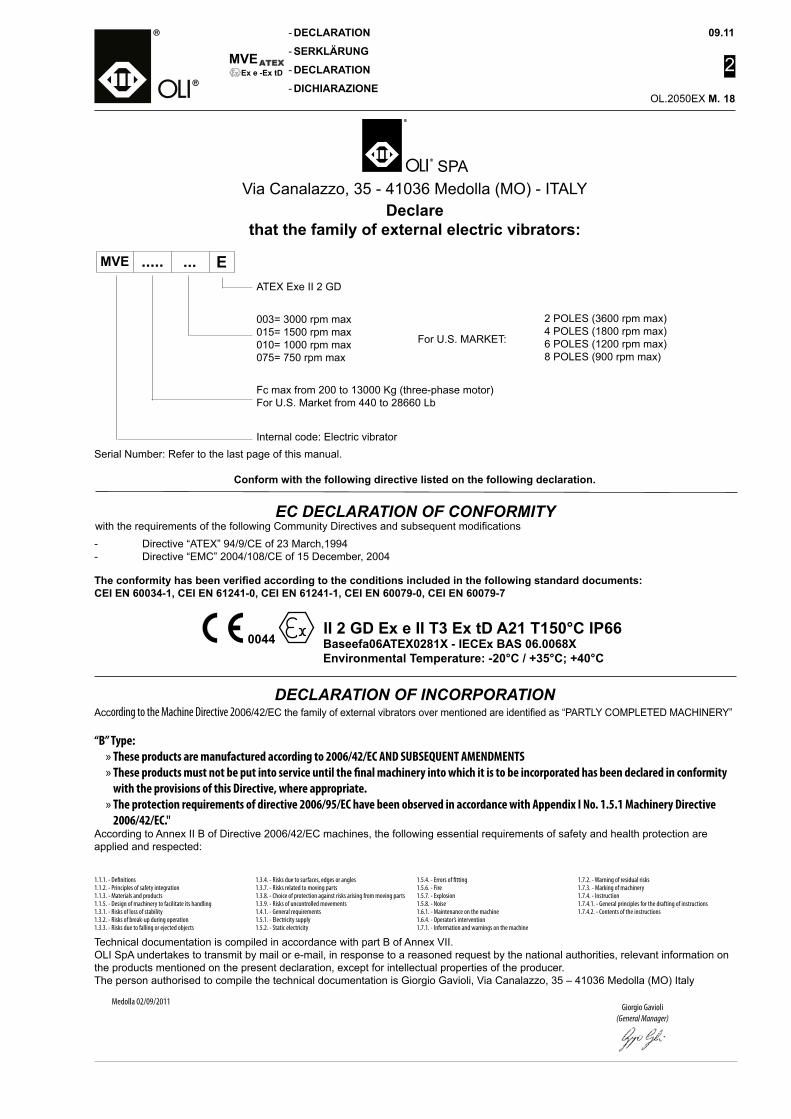
09.11
2
OL.2050EX M.
MVE
-
-
-
-Ex e -Ex tD
DECLARATION
SERKLÄRUNG
DECLARATION
DICHIARAZIONE18
EC DECLARATION OF CONFORMITYwith the requirements of the following Community Directives and subsequent modifications
Serial Number: Refer to the last page of this manual.
Conform with the following directive listed on the following declaration.
- Directive “ATEX” 94/9/CE of 23 March,1994- Directive “EMC” 2004/108/CE of 15 December, 2004
The conformity has been verified according to the conditions included in the following standard documents:CEI EN 60034-1, CEI EN 61241-0, CEI EN 61241-1, CEI EN 60079-0, CEI EN 60079-7
Declarethat the family of external electric vibrators:
Internal code: Electric vibrator
MVE ..... ... E
For U.S. MARKET:
2 POLES (3600 rpm max)4 POLES (1800 rpm max)6 POLES (1200 rpm max)8 POLES (900 rpm max)
ATEX Exe II 2 GD
Fc max from 200 to 13000 Kg (three-phase motor)For U.S. Market from 440 to 28660 Lb
003= 3000 rpm max015= 1500 rpm max010= 1000 rpm max075= 750 rpm max
0044 II 2 GD Ex e II T3 Ex tD A21 T150°C IP66
Baseefa06ATEX0281X - IECEx BAS 06.0068XEnvironmental Temperature: -20°C / +35°C; +40°C
DECLARATION OF INCORPORATIONAccording to the Machine Directive 2006/42/EC the family of external vibrators over mentioned are identified as “PARTLY COMPLETED MACHINERY”
“B” Type: » These products are manufactured according to 2006/42/EC AND SUBSEQUENT AMENDMENTS » These products must not be put into service until the final machinery into which it is to be incorporated has been declared in conformity with the provisions of this Directive, where appropriate. » The protection requirements of directive 2006/95/EC have been observed in accordance with Appendix I No. 1.5.1 Machinery Directive 2006/42/EC."
According to Annex II B of Directive 2006/42/EC machines, the following essential requirements of safety and health protection are applied and respected:
Medolla 02/09/2011Giorgio Gavioli
(General Manager)
Technical documentation is compiled in accordance with part B of Annex VII.OLI SpA undertakes to transmit by mail or e-mail, in response to a reasoned request by the national authorities, relevant information on the products mentioned on the present declaration, except for intellectual properties of the producer. The person authorised to compile the technical documentation is Giorgio Gavioli, Via Canalazzo, 35 – 41036 Medolla (MO) Italy
1.1.1. - Definitions 1.1.2. - Principles of safety integration 1.1.3. - Materials and products 1.1.5. - Design of machinery to facilitate its handling 1.3.1. - Risks of loss of stability 1.3.2. - Risks of break-up during operation 1.3.3. - Risks due to falling or ejected objects
1.3.4. - Risks due to surfaces, edges or angles 1.3.7. - Risks related to moving parts 1.3.8. - Choice of protection against risks arising from moving parts 1.3.9. - Risks of uncontrolled movements 1.4.1. - General requirements 1.5.1. - Electricity supply 1.5.2. - Static electricity
1.5.4. - Errors of fitting 1.5.6. - Fire1.5.7. - Explosion1.5.8. - Noise 1.6.1. - Maintenance on the machine 1.6.4. - Operator’s intervention 1.7.1. - Information and warnings on the machine
1.7.2. - Warning of residual risks 1.7.3. - Marking of machinery 1.7.4. - Instruction 1.7.4.1. - General principles for the drafting of instructions 1.7.4.2. - Contents of the instructions
SPA Via Canalazzo, 35 - 41036 Medolla (MO) - ITALY
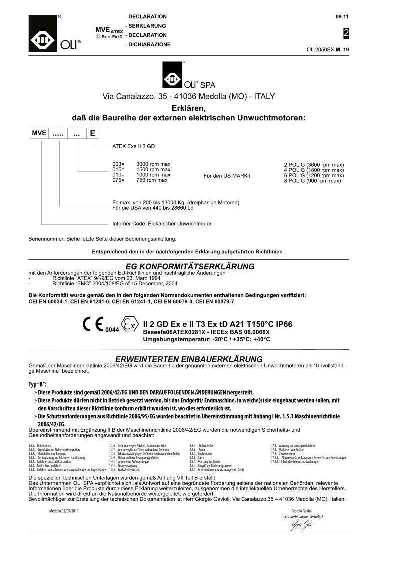
MVE
-
-
-
-
09.11
2
OL.2050EX M.
Ex e -Ex tD
DECLARATION
SERKLÄRUNG
DECLARATION
DICHIARAZIONE19
Erklären, daß die Baureihe der externen elektrischen Unwuchtmotoren:
Seriennummer: Siehe letzte Seite dieser Bedienungsanleitung.
Entsprechend den in der nachfolgenden Erklärung aufgeführten Richtlinien .
EG KONFORMITÄTSERKLÄRUNGmit den Anforderungen der folgenden EU-Richtlinien und nachträgliche Änderungen- Richtlinie “ATEX” 94/9/EG vom 23. März 1994- Richtlinie “EMC” 2004/108/EG of 15 December, 2004
Die Konformität wurde gemäß den in den folgenden Normendokumenten enthaltenen Bedingungen verifiziert:CEI EN 60034-1, CEI EN 61241-0, CEI EN 61241-1, CEI EN 60079-0, CEI EN 60079-7
003= 3000 rpm max015= 1500 rpm max010= 1000 rpm max075= 750 rpm max
Fc max. von 200 bis 13000 Kg. (dreiphasige Motoren) Für die USA von 440 bis 28660 Lb
Interner Code: Elektrischer Unwuchtmotor
MVE ..... ... E
Für den US MARKT:
2 POLIG (3600 rpm max)4 POLIG (1800 rpm max)6 POLIG (1200 rpm max)8 POLIG (900 rpm max)
ATEX Exe II 2 GD
ERWEINTERTEN EINBAUERKLÄRUNGGemäß der Maschinenrichtlinie 2006/42/EG wird die Baureihe der genannten externen elektrischen Unwuchtmotoren als “Unvollständi-ge Maschine” bezeichnet.
Typ “B”: » Diese Produkte sind gemäß 2006/42/EG UND DEN DARAUFFOLGENDEN ÄNDERUNGEN hergestellt. » Diese Produkte dürfen nicht in Betrieb gesetzt werden, bis das Endgerät/ Endmaschine, in welche(s) sie eingebaut werden sollen, mit den Vorschriften dieser Richtlinie konform erklärt worden ist, wo dies erforderlich ist. » Die Schutzanforderungen aus Richtlinie 2006/95/EG wurden beachtet in Übereinstimmung mit Anhang I Nr. 1.5.1 Maschinenrichtlinie 2006/42/EG.
Übereinstimmend mit Ergänzung II B der Maschinenrichtlinie 2006/42/EG wurden die notwendigen Sicherheits- und Gesundheitsanforderungen angewandt und beachtet:
Giorgio Gavioli(rechtsverbindlicher Vertreter)
Die speziellen technischen Unterlagen wurden gemäß Anhang VII Teil B erstelltDas Unternehmen OLI SPA verpflichtet sich, als Antwort auf eine begründete Forderung seitens der nationalen Behörden, relevante Informationen über die Produkte durch diese Erklärung weiterzuleiten, ausgenommen die intellektuellen Urheberrechte des Herstellers. Die Information wird direkt an die Nationalbehörde weitergeleitet, wie gefordert.Bevollmächtiger zur Erstellung der technischen Dokumentation ist Herr Giorgio Gavioli, Via Canalazzo,35 – 41036 Medolla (MO), Italien.
1.1.1. - Definitionen1.1.2. - Grundsätze zur Sicherheitsintegration1.1.3. - Materialien und Produkte1.1.5. - Geräteplanung zur leichteren Handhabung1.3.1. - Gefahren aus Stabilitätsverlust1.3.2. - Reiß-/ Bruchgefahren1.3.3. - Gefahren von fallenden oder ausgeschleuderten Gegenständen
1.3.4. - Gefahren wegen Flächen, Kanten oder Ecken1.3.7. - mit beweglichen Teilen verbundene Gefahren1.3.8. - Schutzauswahl gegen Gefahren von beweglichen Teilen 1.3.9. - Unkontrollierte Bewegungsgefahren1.4.1. - Allgemeine Anforderungen1.5.1. - Stromversorgung1.5.2. - Statische Elektrizität
1.5.4. - Einbaufehler1.5.6. - Feuer1.5.7. - Explosionen1.5.8. - Lärm1.6.1. - Wartung des Geräts1.6.4. - Eingriff der Bedienungsperson 1.7.1. - Informationen und Warnungen am Gerät
1.7.2. - Warnung vor sonstigen Gefahren1.7.3. - Markieren von Geräten1.7.4. - Unterweisung1.7.4.1. - Allgemeine Grundsätze zum Entwerfen von Anweisungen1.7.4.2. - Inhalt der Gebrauchsanweisungen
SPA Via Canalazzo, 35 - 41036 Medolla (MO) - ITALY
Medolla 02/09/2011
0044 II 2 GD Ex e II T3 Ex tD A21 T150°C IP66
Baseefa06ATEX0281X - IECEx BAS 06.0068XUmgebungstemperatur: -20°C / +35°C; +40°C
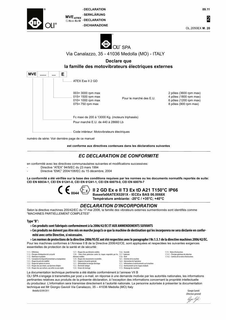
09.11
2
OL.2050EX M.
MVE
-
-
-
-Ex e -Ex tD
DECLARATION
SERKLÄRUNG
DECLARATION
DICHIARAZIONE20
EC DECLARATION DE CONFORMITEen conformité avec les directives communautaires suivantes et modifications successives:- Directive “ATEX” 94/9/EC du 23 mars 1994- Directive “EMC” 2004/108/EC du 15 décembre, 2004
La conformité a été vérifiée sur la base des conditions requises par les normes ou les documents normatifs reportés de suite:CEI EN 60034-1, CEI EN 61241-0, CEI EN 61241-1, CEI EN 60079-0, CEI EN 60079-7
numéro de série: Voir dernière page de ce manuel
est conforme aux directives contenues dans les déclarations suivantes
Declare quela famille des motovibrateurs électriques externes
003= 3000 rpm max015= 1500 rpm max010= 1000 rpm max075= 750 rpm max
Fc maxi de 200 à 13000 Kg. (moteurs triphasés)Pour marché E.U. de 440 à 28660 Lb
Code intérieur: Motovibrateurs électriques
MVE ..... ... E
Pour le marché des E.U.
2 pôles (3600 rpm max)4 pôles (1800 rpm max)6 pôles (1200 rpm max)8 pôles (900 rpm max)
DECLARATION D'INCORPORATIONSelon la directive machines 200/42/EC du 17 mai 2006, la famille des vibrateurs externes surmentionnés sont identifiés comme "MACHINES PARTIELLEMENT COMPLETES"
Type “B”: » Ces produits sont fabriqués conformément à la 2006/42/EC ET AUX AMMENDEMENTS SUIVANTS » Ces produits ne doivent pas être mis en marche jusqu’à ce que la machine de destination qui les incorporera ne sera déclarée en confor-mité avec cette Directive, si nécessaire. » Les normes de protections de la directive 2006/95/EC ont été respectées avec le paragraphe I Nr.1.5.1 de la directive machines 2006/42/EC.
Pour les machines conformes à l’Annexe II B de la Directive 2006/42/CE, sont appliquées et respectées les suivantes exigences essentielles de protection de la santé et de sécurité:
Giorgio Gavioli(Directeur general)
La documentation technique pertinente a été établie conformément à l’annexe VII BOLI SPA s’engage à transmettre,par post u e-mail, en réponse à une demande motivée par les autorités nationales, les informations pertinantes relatives aux produits de la présente déclaration, à l’exception des informations concernant la propriété intellectuelle du producteur. L’information sera transmise directement à l’autorité nationale. La personne autorisée à présenter la documentation technique est Mr Giorgio Gavioli Via Canalazzo, 35 – 41036 Medolla (MO) Italy
1.1.1. - Définitions1.1.2. - Principes d’intégration de la sécurité1.1.3. - Matériaux et produits1.1.5. - Conception du dispositif permettant sa manipulation1.3.1. - Risque de perte de stabilité1.3.2. - Risque de rupture en service1.3.3. - Risques dus aux chutes, aux éjections d’objets1.3.4. - Risques dus aux surfaces, aux arêtes ou aux angles
1.3.7. - Risques liés aux éléments mobiles1.3.8. - Choix d’une protection contre les risques engendrés par les éléments mobiles1.3.9. - Risques des mouvements incontrôlés1.4.1. - Exigences de portée générale1.5.1. - Alimentation en énergie électrique1.5.2. - Électricité statique1.5.4. - Erreurs de montage
1.5.6. - Incendie1.5.7 - Explosion1.5.8. - Bruit1.6.1. - Entretien de la machine1.6.4. - Intervention de l’opérateur1.7.1. - Informations et avertissements sur la machine1.7.2. - Avertissement sur les risques résiduels1.7.3. - Marquage des machines
1.7.4. - Notice d’instructions1.7.4.1. - Principes généraux de rédaction 1.7.4.2. - Contenu de la notice d’instructions
SPA Via Canalazzo, 35 - 41036 Medolla (MO) - ITALY
Medolla 02/09/2011
ATEX Exe II 2 GD
0044 II 2 GD Ex e II T3 Ex tD A21 T150°C IP66
Baseefa06ATEX0281X - IECEx BAS 06.0068XTempérature ambiante: -20°C / +35°C; +40°C
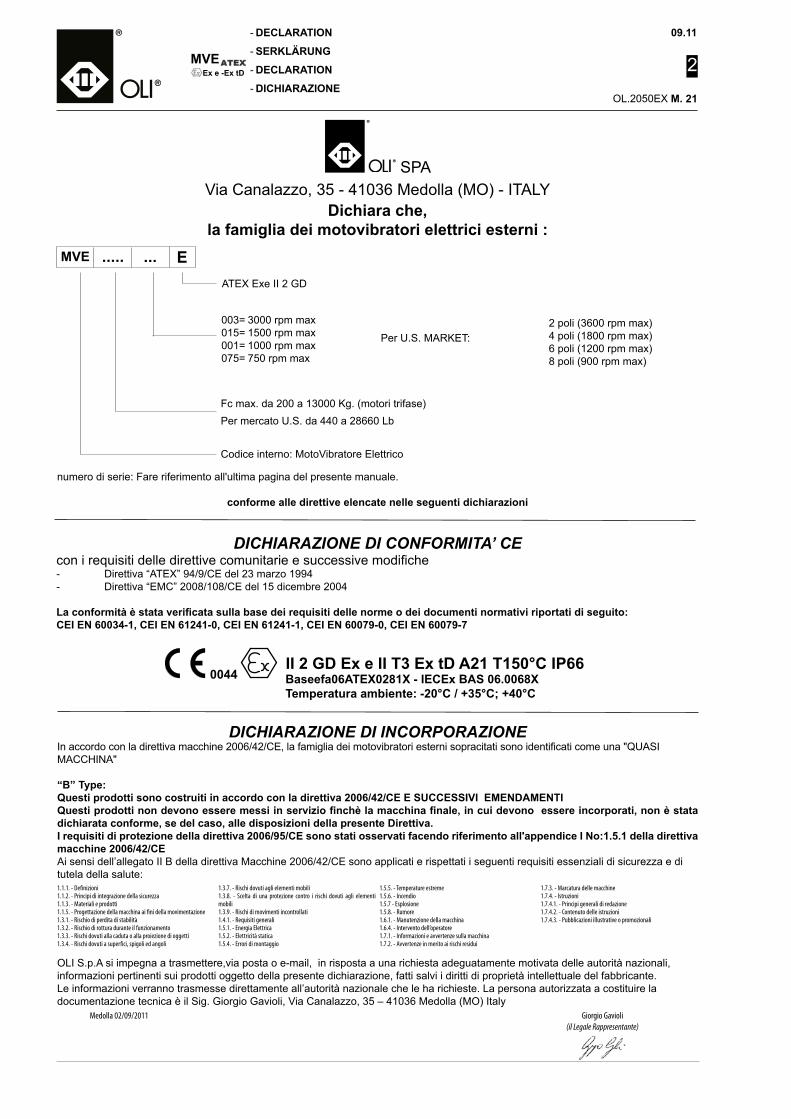
MVE
-
-
-
-
09.11
2
OL.2050EX M.
Ex e -Ex tD
DECLARATION
SERKLÄRUNG
DECLARATION
DICHIARAZIONE21
Dichiara che,la famiglia dei motovibratori elettrici esterni :
DICHIARAZIONE DI CONFORMITA’ CEcon i requisiti delle direttive comunitarie e successive modifiche- Direttiva “ATEX” 94/9/CE del 23 marzo 1994- Direttiva “EMC” 2008/108/CE del 15 dicembre 2004
La conformità è stata verificata sulla base dei requisiti delle norme o dei documenti normativi riportati di seguito:CEI EN 60034-1, CEI EN 61241-0, CEI EN 61241-1, CEI EN 60079-0, CEI EN 60079-7
003= 3000 rpm max015= 1500 rpm max001= 1000 rpm max075= 750 rpm max
Fc max. da 200 a 13000 Kg. (motori trifase)Per mercato U.S. da 440 a 28660 Lb
Codice interno: MotoVibratore Elettrico
MVE ..... ... E
Per U.S. MARKET:2 poli (3600 rpm max)4 poli (1800 rpm max)6 poli (1200 rpm max)8 poli (900 rpm max)
ATEX Exe II 2 GD
DICHIARAZIONE DI INCORPORAZIONEIn accordo con la direttiva macchine 2006/42/CE, la famiglia dei motovibratori esterni sopracitati sono identificati come una "QUASI MACCHINA"
“B” Type:Questi prodotti sono costruiti in accordo con la direttiva 2006/42/CE E SUCCESSIVI EMENDAMENTIQuesti prodotti non devono essere messi in servizio finchè la macchina finale, in cui devono essere incorporati, non è stata dichiarata conforme, se del caso, alle disposizioni della presente Direttiva.I requisiti di protezione della direttiva 2006/95/CE sono stati osservati facendo riferimento all'appendice I No:1.5.1 della direttiva macchine 2006/42/CEAi sensi dell’allegato II B della direttiva Macchine 2006/42/CE sono applicati e rispettati i seguenti requisiti essenziali di sicurezza e di tutela della salute:
Medolla 02/09/2011 Giorgio Gavioli(il Legale Rappresentante)
OLI S.p.A si impegna a trasmettere,via posta o e-mail, in risposta a una richiesta adeguatamente motivata delle autorità nazionali, informazioni pertinenti sui prodotti oggetto della presente dichiarazione, fatti salvi i diritti di proprietà intellettuale del fabbricante. Le informazioni verranno trasmesse direttamente all’autorità nazionale che le ha richieste. La persona autorizzata a costituire la documentazione tecnica è il Sig. Giorgio Gavioli, Via Canalazzo, 35 – 41036 Medolla (MO) Italy
1.1.1. - Definizioni1.1.2. - Principi di integrazione della sicurezza1.1.3. - Materiali e prodotti1.1.5. - Progettazione della macchina ai fini della movimentazione1.3.1. - Rischio di perdita di stabilità1.3.2. - Rischio di rottura durante il funzionamento1.3.3. - Rischi dovuti alla caduta o alla proiezione di oggetti1.3.4. - Rischi dovuti a superfici, spigoli ed angoli
1.3.7. - Rischi dovuti agli elementi mobili1.3.8. - Scelta di una protezione contro i rischi dovuti agli elementi mobili1.3.9. - Rischi di movimenti incontrollati1.4.1. - Requisiti generali1.5.1. - Energia Elettrica1.5.2. - Elettricità statica1.5.4. - Errori di montaggio
1.5.5. - Temperature estreme1.5.6. - Incendio1.5.7 - Esplosione1.5.8. - Rumore1.6.1. - Manutenzione della macchina1.6.4. - Intervento dell’operatore1.7.1. - Informazioni e avvertenze sulla macchina1.7.2. - Avvertenze in merito ai rischi residui
1.7.3. - Marcatura delle macchine1.7.4. - Istruzioni1.7.4.1. - Principi generali di redazione1.7.4.2. - Contenuto delle istruzioni1.7.4.3. - Pubblicazioni illustrative o promozionali
SPA Via Canalazzo, 35 - 41036 Medolla (MO) - ITALY
numero di serie: Fare riferimento all'ultima pagina del presente manuale.
conforme alle direttive elencate nelle seguenti dichiarazioni
0044 II 2 GD Ex e II T3 Ex tD A21 T150°C IP66
Baseefa06ATEX0281X - IECEx BAS 06.0068XTemperatura ambiente: -20°C / +35°C; +40°C
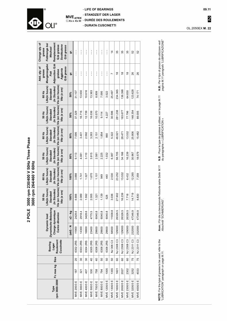
09.11
2
OL.2050EX M.
MVE
-
-
-
-Ex e -Ex tD
LIFE OF BEARINGS
STANDZEIT DER LAGER
DURÉE DES ROULEMENTS
DURATA CUSCINETTI2
POLE
30
00 rp
m 2
30/4
00 V
50H
z Th
ree
Phas
e
3600
rpm
264
/460
V 6
0Hz
NO
TE: F
or th
e ty
pe o
f gre
ase
to b
e us
ed, r
efer
to th
e “L
UB
RIC
ATIO
N” p
arag
raph
on
page
M.1
1.A
nm.:
Für d
ie z
u be
nutz
ende
Fet
tsor
te s
iehe
Sei
te M
.11
Abs
chni
tt “S
CH
MIE
RU
NG
”.N
.B. :
Pou
r le
type
de
grai
sse
à ut
ilise
r, vo
ir la
pag
e M
.11
du p
arag
raph
e «
LUB
RIF
ICAT
ION
»N
.B.:
Per
il ti
po d
i gra
sso
da u
tiliz
zare
ved
ipa
gina
M.1
1 pa
ragr
afo
“LU
BR
IFIC
AZI
ON
E”
Type
rpm
360
0-30
00Fc
max
kg
Siz
e
Bea
ring
Lage
rR
oule
men
tC
usci
netto
Dyn
amic
load
Dyn
amis
che
Bela
stun
gC
harg
e dy
nam
ique
Car
ico
dina
mic
o
50 H
zLi
fe(in
hou
rs)
Stan
dzei
t (i
n St
unde
n)Vi
s (e
n he
ures
)Vi
ta (a
ore
)
60 H
zLi
fe(in
hou
rs)
Stan
dzei
t (i
n St
unde
n)Vi
s (e
n he
ures
)Vi
ta (a
ore
)
50 H
zLi
fe(in
hou
rs)
Stan
dzei
t (i
n St
unde
n)Vi
s (e
n he
ures
)Vi
ta (a
ore
)
60 H
zLi
fe(in
hou
rs)
Stan
dzei
t (i
n St
unde
n)Vi
s (e
n he
ures
)Vi
ta (a
ore
)
50 H
zLi
fe(in
hou
rs)
Stan
dzei
t (i
n St
unde
n)Vi
s (e
n he
ures
)Vi
ta (a
ore
)
60 H
zLi
fe(in
hou
rs)
Stan
dzei
t (i
n St
unde
n)Vi
s (e
n he
ures
)Vi
ta (a
ore
)
Add.
qty
. of
grea
seM
enge
nzug
abe
Fett
Adjo
nctio
n Q
.tégr
aiss
eA
ggiu
nta
Q.tà
gra
sso
Cha
nge
qty.
of
grea
seFe
ttmen
ge b
eiW
echs
elR
empl
acem
ent
Q.té
gra
isse
Sost
ituzio
neQ
.tà g
rass
o
(skf
) - N
x2 -
kg10
0%10
0%80
%80
%50
%50
%gr
.gr
.
MV
E 2
00/3
E18
720
6302
2R
S11
900
2428
.64.
666
3.88
89.
113
7.59
537
.329
31.1
07- -
-- -
-
MV
E 3
00/3
E32
130
6303
2R
S14
300
2918
.42.
089
1.74
14.
081
3.40
116
.716
13.9
30- -
-- -
-
MV
E 4
00/3
E40
730
6304
2R
S16
800
3428
.61.
592
1.32
73.
110
2.59
212
.739
10.6
16- -
-- -
-
MV
E 5
00/3
E53
040
6305
2R
S23
400
4775
.52.
005
1.67
03.
915
3.26
316
.036
13.3
63- -
-- -
-
MV
E 7
00/3
E75
840
6306
2R
S29
600
6040
.81.
321
1.10
12.
581
2.15
110
.570
8.80
9- -
-- -
-
MV
E 8
00/3
E79
450
6306
2R
S29
600
6040
.81.
139
949
2.22
51.
854
9.11
47.
595
- - -
- - -
MV
E 1
200/
3 E
1005
5063
06 2
RS
2960
060
40.8
528
440
1.03
286
04.
227
3.52
2- -
-- -
-
MV
E 1
300/
3 E
1355
50N
J 30
6 C
358
500
1193
8.8
3.03
62.
530
6.38
75.
322
30.5
9625
.497
714
MV
E 1
600/
3 E
1601
60N
J 23
08 C
312
9000
2632
6.5
27.9
0223
.252
58.7
0548
.921
281.
238
234.
365
1835
MV
E 2
000/
3 E
2027
60N
J 23
08 C
312
9000
2632
6.5
16.2
3913
.532
34.1
6628
.471
163.
677
136.
398
1835
MV
E 2
300/
3 E
2302
60N
J 23
08 C
312
9000
2632
6.5
7.71
86.
432
16.2
3913
.532
77.7
9664
.830
1835
MV
E 3
200/
3 E
3252
75N
J 23
11 C
323
2000
4734
6.9
14.7
1912
.265
30.9
6725
.806
148.
354
123.
628
2652
MV
E 4
000/
3 E
4033
75N
J 23
11 C
323
2000
4734
6.9
8.83
07.
359
18.5
7915
.482
89.0
0574
.171
2652
22
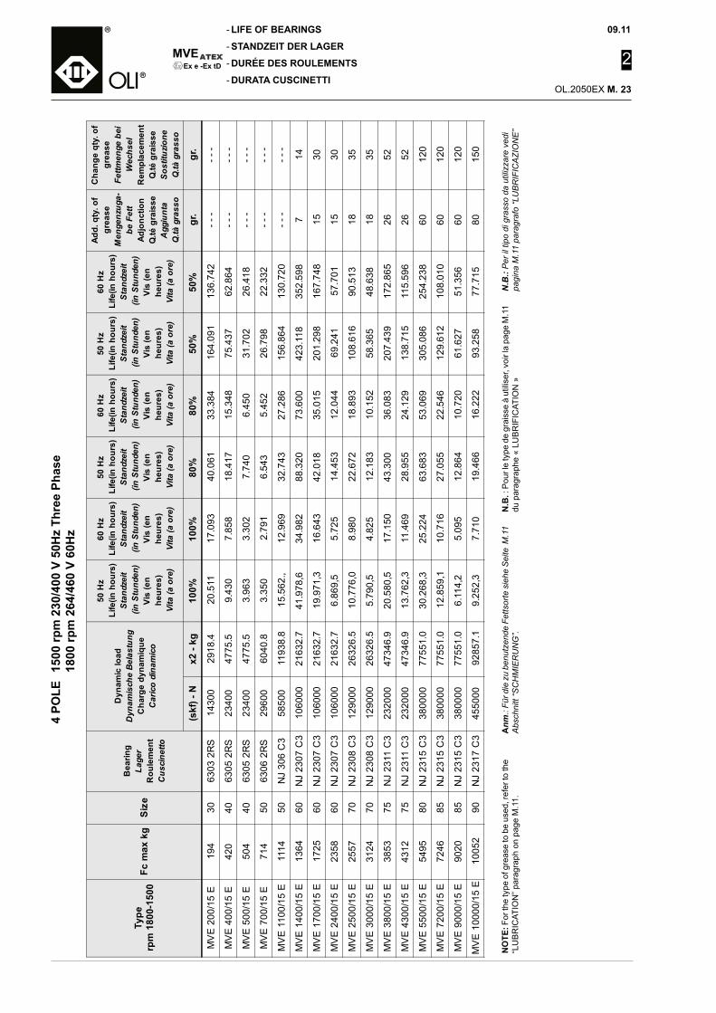
MVE
-
-
-
-
09.11
2
OL.2050EX M.
Ex e -Ex tD4
POLE
150
0 rp
m 2
30/4
00 V
50H
z Th
ree
Phas
e
1800
rpm
264
/460
V 6
0Hz
LIFE OF BEARINGS
STANDZEIT DER LAGER
DURÉE DES ROULEMENTS
DURATA CUSCINETTI
NO
TE: F
or th
e ty
pe o
f gre
ase
to b
e us
ed, r
efer
to th
e “L
UB
RIC
ATIO
N” p
arag
raph
on
page
M.1
1.A
nm.:
Für d
ie z
u be
nutz
ende
Fet
tsor
te s
iehe
Sei
te M
.11
Abs
chni
tt “S
CH
MIE
RU
NG
”.N
.B. :
Pou
r le
type
de
grai
sse
à ut
ilise
r, vo
ir la
pag
e M
.11
du p
arag
raph
e «
LUB
RIF
ICAT
ION
»N
.B.:
Per
il ti
po d
i gra
sso
da u
tiliz
zare
ved
ipa
gina
M.1
1 pa
ragr
afo
“LU
BR
IFIC
AZI
ON
E”
Type
rpm
180
0-15
00Fc
max
kg
Size
Bea
ring
Lage
rR
oule
men
tC
usci
netto
Dyn
amic
load
Dyn
amis
che
Bela
stun
gC
harg
e dy
nam
ique
Car
ico
dina
mic
o
50 H
zLi
fe(in
hou
rs)
Stan
dzei
t (i
n St
unde
n)Vi
s (e
nhe
ures
)Vi
ta (a
ore
)
60 H
zLi
fe(in
hou
rs)
Stan
dzei
t (i
n St
unde
n)Vi
s (e
nhe
ures
)Vi
ta (a
ore
)
50 H
zLi
fe(in
hou
rs)
Stan
dzei
t (i
n St
unde
n)Vi
s (e
nhe
ures
)Vi
ta (a
ore
)
60 H
zLi
fe(in
hou
rs)
Stan
dzei
t (i
n St
unde
n)Vi
s (e
nhe
ures
)Vi
ta (a
ore
)
50 H
zLi
fe(in
hou
rs)
Stan
dzei
t (i
n St
unde
n)Vi
s (e
nhe
ures
)Vi
ta (a
ore
)
60 H
zLi
fe(in
hou
rs)
Stan
dzei
t (i
n St
unde
n)Vi
s (e
nhe
ures
)Vi
ta (a
ore
)
Add.
qty
. of
grea
seM
enge
nzug
a-be
Fet
tAd
jonc
tion
Q.té
gra
isse
Agg
iunt
aQ
.tà g
rass
o
Cha
nge
qty.
of
grea
seFe
ttmen
ge b
eiW
echs
elR
empl
acem
ent
Q.té
gra
isse
Sost
ituzio
neQ
.tà g
rass
o
(skf
) - N
x2 -
kg10
0%10
0%80
%80
%50
%50
%gr
.gr
.
MV
E 2
00/1
5 E
194
3063
03 2
RS
1430
029
18.4
20.5
1117
.093
40.0
6133
.384
164.
091
136.
742
- - -
- - -
MV
E 4
00/1
5 E
420
4063
05 2
RS
2340
047
75.5
9.43
07.
858
18.4
1715
.348
75.4
3762
.864
- - -
- - -
MV
E 5
00/1
5 E
504
4063
05 2
RS
2340
047
75.5
3.96
33.
302
7.74
06.
450
31.7
0226
.418
- - -
- - -
MV
E 7
00/1
5 E
714
5063
06 2
RS
2960
060
40.8
3.35
02.
791
6.54
35.
452
26.7
9822
.332
- - -
- - -
MV
E 1
100/
15 E
1114
50N
J 30
6 C
358
500
1193
8.8
15.5
62.,
12.9
6932
.743
27.2
8615
6.86
413
0.72
0- -
-- -
-
MV
E 1
400/
15 E
1364
60N
J 23
07 C
310
6000
2163
2.7
41.9
78,6
34.9
8288
.320
73.6
0042
3.11
835
2.59
87
14
MV
E 1
700/
15 E
1725
60N
J 23
07 C
310
6000
2163
2.7
19.9
71,3
16.6
4342
.018
35.0
1520
1.29
816
7.74
815
30
MV
E 2
400/
15 E
2358
60N
J 23
07 C
310
6000
2163
2.7
6.86
9,5
5.72
514
.453
12.0
4469
.241
57.7
0115
30
MV
E 2
500/
15 E
2557
70N
J 23
08 C
312
9000
2632
6.5
10.7
76,0
8.98
022
.672
18.8
9310
8.61
690
.513
1835
MV
E 3
000/
15 E
3124
70N
J 23
08 C
312
9000
2632
6.5
5.79
0,5
4.82
512
.183
10.1
5258
.365
48.6
3818
35
MV
E 3
800/
15 E
3853
75N
J 23
11 C
323
2000
4734
6.9
20.5
80,5
17.1
5043
.300
36.0
8320
7.43
917
2.86
526
52
MV
E 4
300/
15 E
4312
75N
J 23
11 C
323
2000
4734
6.9
13.7
62,3
11.4
6928
.955
24.1
2913
8.71
511
5.59
626
52
MV
E 5
500/
15 E
5495
80N
J 23
15 C
338
0000
7755
1.0
30.2
68,3
25.2
2463
.683
53.0
6930
5.08
625
4.23
860
120
MV
E 7
200/
15 E
7246
85N
J 23
15 C
338
0000
7755
1.0
12.8
59,1
10.7
1627
.055
22.5
4612
9.61
210
8.01
060
120
MV
E 9
000/
15 E
9020
85N
J 23
15 C
338
0000
7755
1.0
6.11
4,2
5.09
512
.864
10.7
2061
.627
51.3
5660
120
MV
E 1
0000
/15
E10
052
90N
J 23
17 C
345
5000
9285
7.1
9.25
2,3
7.71
019
.466
16.2
2293
.258
77.7
1580
150
23
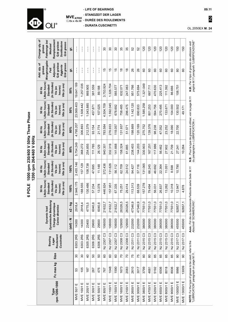
09.11
2
OL.2050EX M.
MVE
-
-
-
-Ex e -Ex tD
6 PO
LE 1
000
rpm
230
/400
V 5
0Hz
Thre
e Ph
ase
12
00 rp
m 2
64/4
60 V
60H
z
LIFE OF BEARINGS
STANDZEIT DER LAGER
DURÉE DES ROULEMENTS
DURATA CUSCINETTI
NO
TE: F
or th
e ty
pe o
f gre
ase
to b
e us
ed, r
efer
to th
e “L
UB
RIC
ATIO
N” p
arag
raph
on
page
M.1
1.A
nm.:
Für d
ie z
u be
nutz
ende
Fet
tsor
te s
iehe
Sei
te M
.11
Abs
chni
tt “S
CH
MIE
RU
NG
”.N
.B. :
Pou
r le
type
de
grai
sse
à ut
ilise
r, vo
ir la
pag
e M
.11
du p
arag
raph
e «
LUB
RIF
ICAT
ION
»N
.B.:
Per
il ti
po d
i gra
sso
da u
tiliz
zare
ved
ipa
gina
M.1
1 pa
ragr
afo
“LU
BR
IFIC
AZI
ON
E”
Type
rpm
120
0-10
00Fc
max
kg
Size
Bea
ring
Lage
rR
oule
men
tC
usci
netto
Dyn
amic
load
Dyn
amis
che
Bela
stun
gC
harg
e dy
nam
ique
Car
ico
dina
mic
o
50 H
zLi
fe(in
hou
rs)
Stan
dzei
t (i
n St
unde
n)Vi
s (e
nhe
ures
)Vi
ta (a
ore
)
60 H
zLi
fe(in
hou
rs)
Stan
dzei
t (i
n St
unde
n)Vi
s (e
nhe
ures
)Vi
ta (a
ore
)
50 H
zLi
fe(in
hou
rs)
Stan
dzei
t (i
n St
unde
n)Vi
s (e
nhe
ures
)Vi
ta (a
ore
)
60 H
zLi
fe(in
hou
rs)
Stan
dzei
t (i
n St
unde
n)Vi
s (e
nhe
ures
)Vi
ta (a
ore
)
50 H
zLi
fe(in
hou
rs)
Stan
dzei
t (i
n St
unde
n)Vi
s (e
nhe
ures
)Vi
ta (a
ore
)
60 H
zLi
fe(in
hou
rs)
Stan
dzei
t (i
n St
unde
n)Vi
s (e
nhe
ures
)Vi
ta (a
ore
)
Add.
qty
. of
grea
seM
enge
nzug
abe
Fett
Adjo
nctio
nQ
.té g
rais
seA
ggiu
nta
Q.tà
gra
sso
Cha
nge
qty.
of
grea
seFe
ttmen
ge b
eiW
echs
elR
empl
acem
ent
Q.té
gra
isse
Sost
ituzio
neQ
.tà g
rass
o
(skf
) - N
x2 -
kg10
0%10
0%80
%80
%50
%50
%gr
.gr
.
MV
E 5
0/1
E53
3063
03 2
RS
1430
029
18,4
2.94
6.17
52.
455.
146
5.75
4.24
94.
795.
207
23.5
69.4
0319
.641
.169
- - -
- - -
MV
E 1
00/1
E10
530
6303
2R
S14
300
2918
,418
8.55
515
7.12
936
8.27
230
6.89
31.
508.
442
1.25
7.03
5- -
-- -
-
MV
E 2
00/1
E18
740
6305
2R
S23
400
4775
,513
0.48
610
8.73
825
4.85
521
2.37
91.
043.
885
869.
905
- - -
- - -
MV
E 3
00/1
E26
750
6306
2R
S29
600
6040
,857
.234
47.6
9511
1.78
593
.154
457.
871
381.
559
- - -
- - -
MV
E 5
00/1
E47
550
6306
2R
S29
600
6040
,813
.378
11.1
4826
.129
21.7
7410
7.02
589
.188
- - -
- - -
MV
E 8
00/1
E76
760
NJ
2307
C3
1060
0021
632,
744
6.92
437
2.43
694
0.30
178
3.58
44.
504.
709
3.75
3.92
415
30
MV
E 1
100/
1 E
1048
60N
J 23
07 C
310
6000
2163
2,7
157.
951
131.
626
332.
319
276.
933
1.59
2.04
51.
326.
704
1530
MV
E 1
500/
1 E
1590
60N
J 23
07 C
310
6000
2163
2,7
67.3
3556
.112
141.
668
118.
057
678.
692
565.
577
1530
MV
E 1
600/
1 E
1673
70N
J 23
08 C
312
9000
2632
6,5
75.2
5162
.709
158.
324
131.
937
758.
485
632.
071
1835
MV
E 2
100/
1 E
2083
70N
J 23
08 C
312
9000
2632
6,5
29.4
1424
.512
61.8
8551
.571
296.
475
247.
063
1835
MV
E 2
600/
1 E
2610
75N
J 23
11 C
323
2000
4734
6,9
113.
313
94.4
2723
8.40
319
8.66
91.
142.
120
951.
766
2652
MV
E 3
000/
1 E
3017
75N
J 23
11 C
323
2000
4734
6,9
68.5
3957
.116
144.
203
120.
169
690.
833
575.
694
2652
MV
E 3
800/
1 E
3799
80N
J 23
15 C
338
0000
7755
1,0
157.
278
131.
065
330.
903
275.
752
1.58
5.25
81.
321.
049
6012
0
MV
E 4
700/
1 E
4681
80N
J 23
15 C
338
0000
7755
1,0
79.4
9466
.245
167.
251
139.
376
801.
253
667.
711
6012
0
MV
E 5
200/
1 E
5192
85N
J 23
15 C
338
0000
7755
1,0
56.0
3146
.692
117.
886
98.2
3856
4.75
647
0.63
060
120
MV
E 6
500/
1 E
6506
85N
J 23
15 C
338
0000
7755
1,0
26.8
3722
.364
56.4
6247
.052
270.
495
225.
413
6012
0
MV
E 8
000/
1 E
8018
85N
J 23
15 C
338
0000
7755
1,0
13.2
6211
.051
27.9
0223
.252
133.
671
111.
392
6012
0
MV
E 9
000/
1 E
8936
85N
J 23
15 C
338
0000
7755
1,0
10.3
188.
598
21.7
0918
.090
104.
000
86.6
6660
120
MV
E 1
0000
/1 E
9986
90N
J 23
17 C
345
5000
9285
7,1
12.9
4710
.790
27.2
4122
.700
130.
502
108.
751
8015
0
MV
E 1
3000
/1 E
1300
990
NJ
2317
C3
4550
0092
857,
14.
878
10.2
6449
.171
8015
0
24
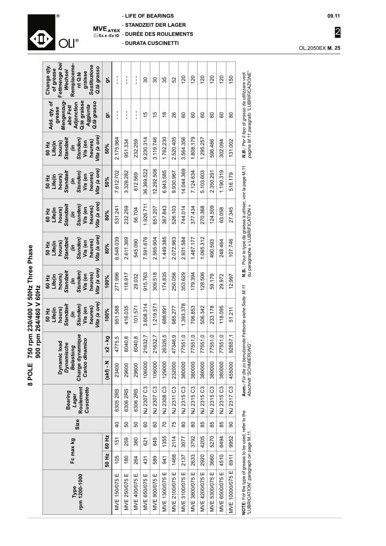
MVE
-
-
-
-
09.11
2
OL.2050EX M.
Ex e -Ex tD8
POLE
750
rpm
230
/400
V 5
0Hz
Thre
e Ph
ase
90
0 rp
m 2
64/4
60 V
60H
z
LIFE OF BEARINGS
STANDZEIT DER LAGER
DURÉE DES ROULEMENTS
DURATA CUSCINETTI
NO
TE: F
or th
e ty
pe o
f gre
ase
to b
e us
ed, r
efer
to th
e “L
UB
RIC
ATIO
N” p
arag
raph
on
page
M.1
1.A
nm.:
Für d
ie z
u be
nutz
ende
Fet
tsor
te s
iehe
Sei
te M
.11
Abs
chni
tt “S
CH
MIE
RU
NG
”.N
.B. :
Pou
r le
type
de
grai
sse
à ut
ilise
r, vo
ir la
pag
e M
.11
du p
arag
raph
e «
LUB
RIF
ICAT
ION
»N
.B.:
Per
il ti
po d
i gra
sso
da u
tiliz
zare
ved
ipa
gina
M.1
1 pa
ragr
afo
“LU
BR
IFIC
AZI
ON
E”
Type
rpm
120
0-10
00Fc
max
kg
Size
Bea
ring
Lage
rR
oule
men
tC
usci
netto
Dyn
amic
load
Dyn
amis
che
Bela
stun
gC
harg
e dy
nam
ique
Car
ico
dina
mic
o
50 H
zLi
fe(in
hour
s)St
andz
eit
(in
Stun
den)
Vis
(en
heur
es)
Vita
(a o
re)
60 H
zLi
fe(in
hour
s)St
andz
eit
(in
Stun
den)
Vis
(en
heur
es)
Vita
(a o
re)
50 H
zLi
fe(in
hour
s)St
andz
eit
(in
Stun
den)
Vis
(en
heur
es)
Vita
(a o
re)
60 H
zLi
fe(in
hour
s)St
andz
eit
(in
Stun
den)
Vis
(en
heur
es)
Vita
(a o
re)
50 H
zLi
fe(in
hour
s)St
andz
eit
(in
Stun
den)
Vis
(en
heur
es)
Vita
(a o
re)
60 H
zLi
fe(in
hour
s)St
andz
eit
(in
Stun
den)
Vis
(en
heur
es)
Vita
(a o
re)
Add.
qty
. of
grea
seM
enge
nzug
-ab
e Fe
ttAd
jonc
tion
Q.té
gra
isse
Agg
iunt
aQ
.tà g
rass
o
Cha
nge
qty.
of g
reas
eFe
ttmen
ge b
eiW
echs
elR
empl
acem
e-nt
Q.té
grai
sse
Sost
ituzio
neQ
.tà g
rass
o
50 H
z60
Hz
(skf
) - N
x2 -
kg10
0%10
0%80
%80
%50
%50
%gr
.gr
.
MV
E 1
50/0
75 E
105
151
4063
05 2
RS
2340
047
75,5
951.
588
271.
996
6.54
8.03
953
1.24
17.
612.
702
2.17
5.96
4- -
-- -
-
MV
E 2
50/0
75 E
180
259
5063
06 2
RS
2960
060
40,8
416.
035
118.
917
2.61
1.36
923
2.25
93.
328.
282
951.
334
- - -
- - -
MV
E 4
00/0
75 E
264
380
5063
06 2
RS
2960
060
40,8
101.
571
29.0
3254
5.09
056
.704
812.
569
232.
259
- - -
- - -
MV
E 6
50/0
75 E
431
621
60N
J 23
07 C
310
6000
2163
2,7
3.60
8.31
491
5.76
37.
591.
676
1.92
6.71
136
.369
.522
9.23
0.31
415
30
MV
E 9
00/0
75 E
589
849
60N
J 23
07 C
310
6000
2163
2,7
1.21
9.57
130
9.51
82.
565.
904
651.
207
12.2
92.5
063.
119.
746
1530
MV
E 1
300/
075
E94
113
5570
NJ
2308
C3
1290
0026
326,
568
8.89
117
4.83
51.
449.
385
367.
843
6.94
3.58
51.
762.
230
1835
MV
E 2
100/
075
E14
6821
1475
NJ
2311
C3
2320
0047
346,
998
5.27
725
0.05
62.
072.
963
526.
103
9.93
0.96
72.
520.
405
2652
MV
E 3
100/
075
E21
3730
7780
NJ
2315
C3
3800
0077
551,
01.
393.
378
353.
629
2.93
1.58
474
4.01
414
.044
.369
3.56
4.35
660
120
MV
E 3
800/
075
E26
3337
9280
NJ
2315
C3
3800
0077
551,
070
6.85
317
9.39
41.
487.
177
377.
434
7.12
4.63
41.
808.
179
6012
0
MV
E 4
200/
075
E29
2042
0585
NJ
2315
C3
3800
0077
551,
050
6.34
212
8.50
61.
065.
312
270.
368
5.10
3.60
31.
295.
257
6012
0
MV
E 5
300/
075
E36
6052
7085
NJ
2315
C3
3800
0077
551,
023
3.17
859
.179
490.
593
124.
509
2.35
0.29
159
6.48
660
120
MV
E 6
500/
075
E45
1064
9485
NJ
2315
C3
3800
0077
551,
011
8.09
529
.972
248.
464
63.0
581.
190.
319
302.
094
6012
0
MV
E 1
0000
/075
E69
1199
5290
NJ
2317
C3
4550
0092
857,
151
.211
12.9
9710
7.74
627
.345
516.
179
131.
002
8015
0
25

SPA
RE
PA
RTS
All
right
s re
serv
ed ©
WA
MG
RO
UP
3
CATALOGUE No. OL.2050EX R.
ISSUEB1
DATE OF LATEST UPDATE
CREATION DATE
09-2011CIRCULATION100
• ELECTRIC EXTERNAL MOTOVIBRATORS SPARE PARTS CATALOGUE
• ELEKTRISCHE AUSSENRÜTTLER ERSATZTEILKATALOG
• MOTOVIBRATEURS EXTERNES ELECTRIQUES PIECES DE RECHANGE
• MOTOVIBRATORI ELETTRICI ESTERNI PEZZI DI RICAMBIO
MVEEx e-Ex tD
II 2 GD Ex e II T3 Ex tD A21 T150°C IP66

SPARE PARTS
ERSATZTEILE
PIECES DE RECHANGE
PEZZI DI RICAMBIO
-
-
-
-
MVE
09.11
3
OL.2050EX R.
Ex e -Ex tD
Per la richiesta di parti di ricambio, occorre specificare:- Tipo di motovibratore- Serie del motovibratore- Tensione di alimentazione- Descrizione della parte di ri-
cambio e numero posizione disegno.
Qualsiasi intervento al motovibra-tore elettrico deve essere effet-tuato da personale specializzato e munito di appositi DPI, prima di intervenire sulla macchina, metterla in sicurezza.
Pour la demande des pièces déta-chées veuillez préciser :- Le Type de motovibrateur- La Série du motovibrateur- La tension d’alimentation- La description de la pièce et le
numéro de position sur le des-sin.
Toutes les interventions sur le motovibrateur doivent être effec-tuées par du personnel spécialisé disposants des E.P.I. appropriés ; avant d’intervenir sur la machine, la mettre en sécurité.
Für die Bestellung von Ersatz-teilen sind folgende Angaben erforderlich:- Typ des Unwuchtmotors- Serien-Nummer des Unwucht-
motors- Betriebsspannung- Beschreibung des Ersatzteils
sowie Positionsnummer in der Zeichnung.
Alle Eingriffe am elektrischen Unwuchtmotor dürfen nur durch spezialisiertes Personal ausge-führt werden, das mit angemes-senen PSA ausgerüstet ist. Vor Eingriffen an der Maschine, muss diese in den sicheren Zustand gebracht werden.
While ordering spare parts, al-ways mention:
- Type of motovibrator- Series of motovibrator- Supply voltage- Description of the spare part and
its item number in the drawing.
All operations on the electric vibrator must be carried out by specialist personnel equipped with special PPD, after setting the machine in safety condition.
01
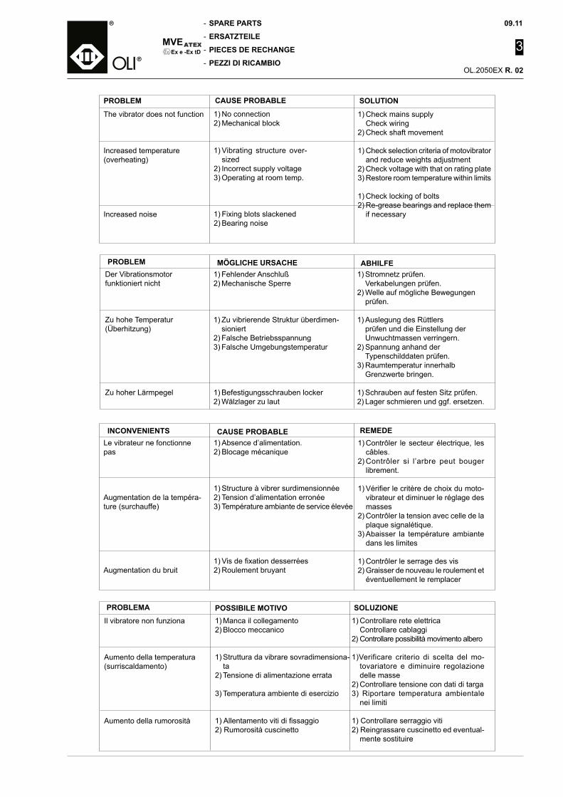
09.11
3
OL.2050EX R.
SPARE PARTS
ERSATZTEILE
PIECES DE RECHANGE
PEZZI DI RICAMBIO
-
-
-
-
MVEEx e -Ex tD
1) No connection2) Mechanical block
1) Vibrating structure over-sized
2) Incorrect supply voltage3) Operating at room temp.
1) Fixing blots slackened2) Bearing noise
PROBLEM CAUSE PROBABLE
The vibrator does not function
Increased temperature (overheating)
Increased noise
1) Check mains supply Check wiring2) Check shaft movement
1) Check selection criteria of motovibrator and reduce weights adjustment
2) Check voltage with that on rating plate3) Restore room temperature within limits
1) Check locking of bolts2) Re-grease bearings and replace them
if necessary
SOLUTION
PROBLEM MÖGLICHE URSACHE ABHILFE1) Fehlender Anschluß2) Mechanische Sperre
1) Zu vibrierende Struktur überdimen-sioniert
2) Falsche Betriebsspannung3) Falsche Umgebungstemperatur
1) Befestigungsschrauben locker2) Wälzlager zu laut
Der Vibrationsmotor funktioniert nicht
Zu hohe Temperatur (Überhitzung)
Zu hoher Lärmpegel
1) Stromnetz prüfen. Verkabelungen prüfen.2) Welle auf mögliche Bewegungen prüfen.
1) Auslegung des Rüttlers prüfen und die Einstellung der Unwuchtmassen verringern.2) Spannung anhand der Typenschilddaten prüfen.3) Raumtemperatur innerhalb Grenzwerte bringen.
1) Schrauben auf festen Sitz prüfen.2) Lager schmieren und ggf. ersetzen.
1) Absence d’alimentation.2) Blocage mécanique
1) Structure à vibrer surdimensionnée2) Tension d’alimentation erronée3) Température ambiante de service élevée
1) Vis de fixation desserrées2) Roulement bruyant
INCONVENIENTS CAUSE PROBABLELe vibrateur ne fonctionne pas
Augmentation de la tempéra-ture (surchauffe)
Augmentation du bruit
1) Contrôler le secteur électrique, les câbles.
2) Contrôler si l’arbre peut bouger librement.
1) Vérifier le critère de choix du moto-vibrateur et diminuer le réglage des masses
2) Contrôler la tension avec celle de la plaque signalétique.
3) Abaisser la température ambiante dans les limites
1) Contrôler le serrage des vis2) Graisser de nouveau le roulement et
éventuellement le remplacer
REMEDE
1) Manca il collegamento2) Blocco meccanico
1) Struttura da vibrare sovradimensiona-ta
2) Tensione di alimentazione errata
3) Temperatura ambiente di esercizio
1) Allentamento viti di fissaggio2) Rumorosità cuscinetto
PROBLEMA POSSIBILE MOTIVOIl vibratore non funziona
Aumento della temperatura(surriscaldamento)
Aumento della rumorosità
1) Controllare rete elettrica Controllare cablaggi2) Controllare possibilità movimento albero
1)Verificare criterio di scelta del mo-tovariatore e diminuire regolazione delle masse
2) Controllare tensione con dati di targa3) Riportare temperatura ambientale
nei limiti
1) Controllare serraggio viti2) Reingrassare cuscinetto ed eventual-
mente sostituire
SOLUZIONE
02
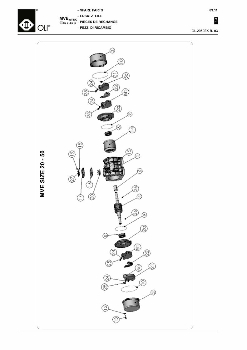
SPARE PARTS
ERSATZTEILE
PIECES DE RECHANGE
PEZZI DI RICAMBIO
-
-
-
-
MVE
09.11
3
OL.2050EX R.
Ex e -Ex tD
MVE
SIZ
E 20
- 50
03
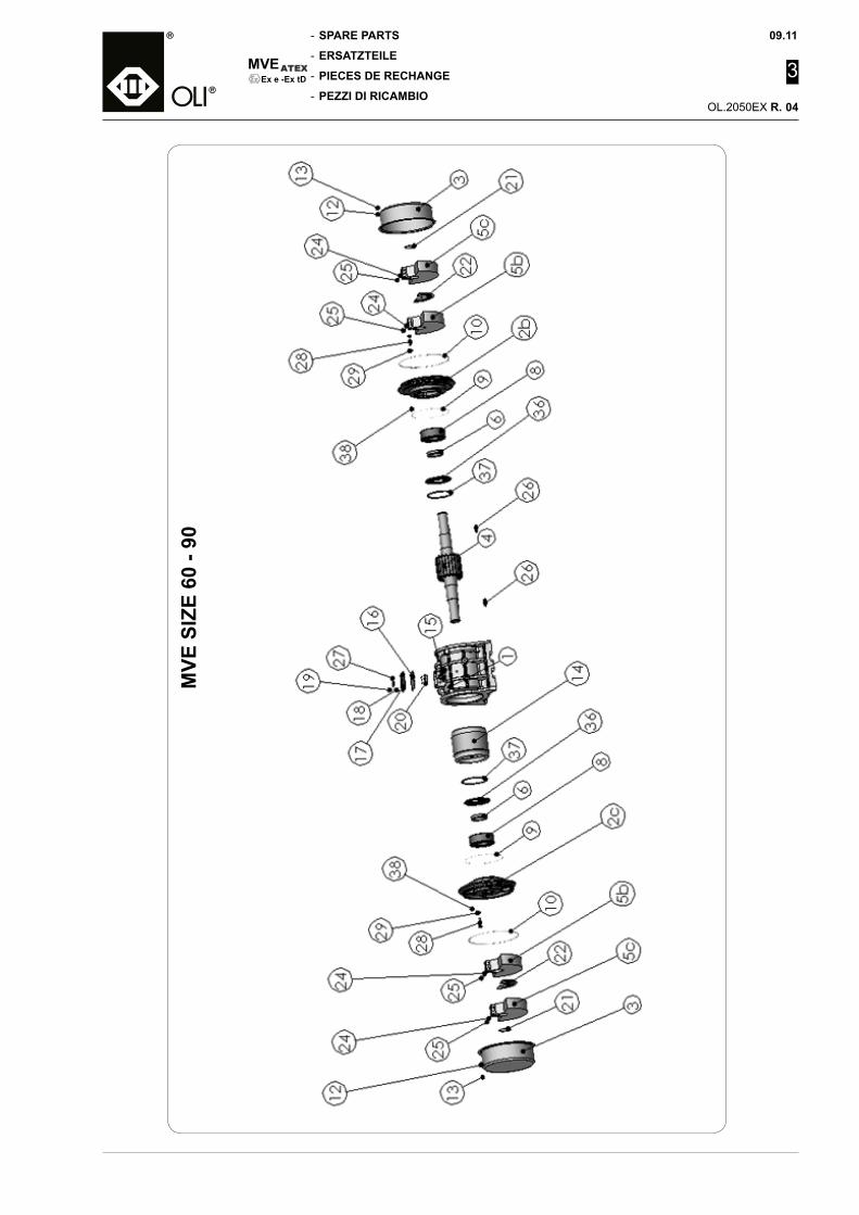
09.11
3
OL.2050EX R.
SPARE PARTS
ERSATZTEILE
PIECES DE RECHANGE
PEZZI DI RICAMBIO
-
-
-
-
MVEEx e -Ex tD
MVE
SIZ
E 60
- 90
04

SPARE PARTS
ERSATZTEILE
PIECES DE RECHANGE
PEZZI DI RICAMBIO
-
-
-
-
MVE
09.11
3
OL.2050EX R.
Ex e -Ex tD
ItemPos.
Q.tyMenge DESCRIPTION BENENNUNG DESIGNATION DENOMINAZIONE
1 1 Motor body Motorgehäuse Carcasse moteur Carcassa motore
1a 1 Motor body left Motorgehäuse links Carcasse moteur gauche Carcassa motore sinistra
1b 1 Motor body right Motorgehäuse rechts Carcasse moteur droite Carcassa motore destra
2a 2 Bearing holder flange Lagerflansch Flasque porte-roulement Flangia portacuscinetto
2b 1 Bearing holder flange right Lagerflansch rechts Flasque porte-roulement droite Flangia portacuscinetto destra
2c 1 Bearing holder flange left Lagerflansch links Flasque porte-roulement gauche Flangia portacuscinetto sinistra
3 2 Weights cover Deckel für Fliehgewichte Couvercie des masses Coperchio masse
4 1 Shaft - rotor Welle - rotor Arbre - rotor Albero - rotore
5a Lamellar weight Lamellenförmige Fliehgewichte Masse à lamelle Massa a lamelle
5b 2 Fixed weight Feste Fliehgewichte Masse fixe Massa fissa
5c 2 Movable weight Bewegliche Fliehgewichte Masse mobile Massa mobile
6 Bearing spacer Abstandhalter wälziager Entretoise roulement Distanziale cuscinetto
7 2 Weights spacer Abstandhalter unwuchtmasse Entretoise masse Distanziale massa
8 2 Bearing Wälziager Roulement Cuscinetto
9 2 Bearing holder flange gasket Dichtung für lagerflansch Joint pour flasque porte-roulement Guarnizione flangia portacuscinetto
10 2 Side cover gasket Dichtung für seitlichen deckel Joint couvercie latéral Guarnizione coperchio laterale
11 2 Nut Mutter Ecrou Dado
12 8 Cover screw washerUnterlegscheibe fürdeckelschraube
Rondelle vis couvercie Rondella vite coperchio
13 8, 10 Cover screw Deckelschraube Vis couvercie Vite coperchio
14 1 Stator with winding Gewickelter ständer Stator enroulé Statore avvolto
15 1 Cable gland Kabelverschraubung Serre-câble Pressacavo
16 1 Terminal board cover gasketDichtung desKlemmenkastendeckels
Joint couvercie bornier Guarnizione coperchio morsettiera
17 1 Terminal board cover Klemmenkastendeckel Couvercie bornier Coperchio morsettiera
18 4 Terminal board cover washerUnterlegscheibe fürKlemmenkastendeckel
Rondelle couvercie bornier Rondella coperchio morsettiera
19 4 Terminal board cover screwSchraube desKlemmenkastendeckels
Vis couvercie bornier Vite coperchio morsettiera
20 1 Terminal board Klemmenleiste Bornier Morsettiera
21 2 Seeger Seeger Seeger Seeger
22 1 Left regulation scale Linker scheibe für unwuchtmasse Disque de gauche de regulation Disco regolazione masse sinistro
23 1 Right regulation scaleRechter scheibe fürunwuchtmasse
Disque de droite de regulation Disco regolazione masse destro
24 4 Weight washerUnterlegscheibe fürunwuchtmasse
Rondelle pour masse Rondella per massa
25 4, 6 Weight screw Schraube für unwuchtmasse Vis pour masse Vite per massa
26 2 Key Passfeder Clavette Chiavetta
27 1 Identification plate Identifikationstypenschild laque signalétique Targhetta di identificazione
28 8 Flange screw Flanschschraube Vis flasque Vite flangia
29 8 Washer Spannstift Rondelle Rondella
30 2 Washer Spannstift Rondelle Rondella
31 1Bushing with brush holderflange
Buchse mit Bürstenflansch Douille avec bride porte balais Bussola con flangia portaspazzole
32 1 Bearing bush Buchse für Lager Bague roulement Boccola cuscinetto
33 1 Motor body gasket Dichtung für motorgehäuse Joint carcasse moteur Guarnizione carcassa motore
34 2 Motor body screw Schraube für motorgehäuse Vis carcasse moteur Vite carcassa motore
35 2 Motor body nutUnterlegscheibe fürmotorgehäuse
Ecrou carcasse moteur Dado carcassa motore
36 2 Grease sealing ring Fettabdichtungsring Bague d'étanchéité graisse Anello di tenuta grasso
37 2 Seeger Seeger Seeger Seeger
38 2 Grease nipple Schmiernippel Graisseur Ingrassatore
05

09.11-
-
-
-
MVEEx e -Ex tD
NOTE
NOTES
NOTES
NOTE OL.2050EX

09.11
OL.2050EX T.
MVEEx e -Ex tD
- NOTE
- NOTES
- NOTES
- NOTE
N.B. Rights reserved to modify technical specificationsN.B. Angaben ohne Gewähr. Änderungen können ohne Vorankündigung vorgenommen werden.N.B. Toutes données portées dans le présent catalogue n’engagent pas le fabricant. Elles peuvent être modifiéès à tout moment.N.B. Tutti i dati riportati nel presente catalogo non sono impegnativi e possono subire variazioni in qualsiasi momento.
OLI SPAVia Canalazzo, 35 I - 41036 Medolla - (MO) ITALY
fax
e-mailinternet
+39 / 0535 / 410611+39 / 0535 / [email protected]
Serial NumberSeriennummerNuméro de sérieNumero di serie