Embed Size (px)
Citation preview

Chemin de la Madeleine - Z.I. 31130 FLOURENS – France Tél. : +33.(0)5.61.36.06.06 Fax : +33.(0)5.61.83.99.45 Web : www.erems.fr
EPM/MEEMM PAYLOAD AND GSE OPERATION
MANUAL
Réf. : EPM-ERM-MA-0001 Ed./Rév. : 1/E (Iss./Rev.)
Date : 01/06/05
E10
FICHE CHAMPS DE DOCUMENT
CHAMPS A RENSEIGNER PAR LE REDACTEUR
NOM DE L’AFFAIRE OU PROJET EPM/MEEMM
TITRE DU CARTOUCHE
PAYLOAD AND GSE OPERATION MANUAL
TITRE DU DOCUMENT EPM/MEEMM SOUS-TITRE DU
DOCUMENT PAYLOAD AND GSE OPERATION MANUAL
REFERENCE DU DOCUMENT
EPM-ERM-MA-0001
REDACTEUR(S) L. LE BARATOUX
MOTS CLES
NOTE DE PIED DE PAGE
E10
EDITION/REVISION 1/E
DATE EDITION/REVISION 01/06/05
INFORMATIONS CONCERNANT LE MODELE : RENSEIGNE PAR LE SERVICE QUALITE
REFERENCE DU MODELE AVEC
EDITION / REVISION
SQ/MO-T/001/ERM-2/A
DATE ED./REV. 17/05/00
Chemin de la Madeleine - Z.I. 31130 FLOURENS – France Tél. : +33.(0)5.61.36.06.06 Fax : +33.(0)5.61.83.99.45 Web : www.erems.fr
EPM/MEEMM PAYLOAD AND GSE OPERATION
MANUAL
Réf. : EPM-ERM-MA-0001 Ed./Rév. : 1/E (Iss./Rev.)
Date : 01/06/05
E10
EPM/MEEMM
PAYLOAD AND GSE OPERATION MANUAL
MOTS CLES / Keywords :
NOM / FONCTION Name / Fonction
DATE SIGNATURE
Préparé par Prepared by
L. LE BARATOUX System Engineer
Approuvé par Approved by
M.Routelous Quality Manager
Approuvé par Approved by
G. DEJONGHE Project Manager

Chemin de la Madeleine - Z.I. 31130 FLOURENS – France Tél. : +33.(0)5.61.36.06.06 Fax : +33.(0)5.61.83.99.45 Web : www.erems.fr
EPM/MEEMM PAYLOAD AND GSE OPERATION
MANUAL
Réf. : EPM-ERM-MA-0001 Ed./Rév. : 1/E (Iss./Rev.)
Date : 01/06/05 Page : i
E10
LISTE DE DIFFUSION
DISTRIBUTION LIST
NOM / FONCTION NAME / FONCTION
SOCIETE FIRM
Nombre d'exemplaires Number of copies
A. WINKLER
G. DEJONGHE
OHB
EREMS
1
1
Chemin de la Madeleine - Z.I. 31130 FLOURENS – France Tél. : +33.(0)5.61.36.06.06 Fax : +33.(0)5.61.83.99.45 Web : www.erems.fr
EPM/MEEMM PAYLOAD AND GSE OPERATION
MANUAL
Réf. : EPM-ERM-MA-0001 Ed./Rév. : 1/E (Iss./Rev.)
Date : 01/06/05 Page : ii
E10
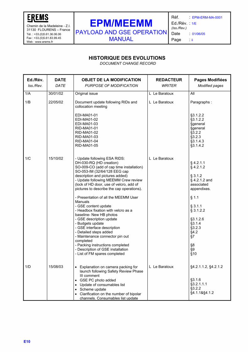
HISTORIQUE DES EVOLUTIONS
DOCUMENT CHANGE RECORD
Ed./Rév. Iss./Rev.
DATE DATE
OBJET DE LA MODIFICATION PURPOSE OF MODIFICATION
REDACTEUR WRITER
Pages Modifiées Modified pages
1/A 1/B 1/C 1/D
30/01/02 22/05/02 15/10/02 15/08/03
Original issue Document update following RIDs and collocation meeting EDI-MA01-01 EDI-MA01-02 EDI-MA01-03 RID-MA01-01 RID-MA01-02 RID-MA01-03 RID-MA01-04 RID-MA01-05 - Update following ESA RIDS: DH-030-RQ (HD creation) SO-009-CO (add of cap time installation) SO-053-IM (32/64/128 EEG cap description and pictures added) - Update following MEEMM Crew review (lock of HD door, use of velcro, add of pictures to describe the cap operations). - Presentation of all the MEEMM User Manuals - GSE content update - Headbox fixation with velcro as a baseline- New HB photos - GSE description update - Budgets update - GSE interface description - Detailed steps added - Maintenance connector pin out completed - Packing instructions completed - Description of GSE installation - List of FM spares completed • Explanation on camera packing for
launch following Safety Review Phase III comment
• GSE PC photo added • Update of consumables list • Scheme update • Clarification on the number of bipolar
channels. Consumables list update
L Le Baratoux L Le Baratoux L Le Baratoux L Le Baratoux
All Paragraphs : §3.1.2.2 §3.1.2.2 §general §general §3.2.2 §3.2.3 §3.1.4.3 §3.1.4.2 § 4.2.1.1 § 4.2.1.2 § 3.1.2 § 4.2.1.2 and associated appendixes. § 1.1 § 3.1.1 § 3.1.2.2 §3.1.2.6 §3.1.4 §3.2.3 §4.2 §7 §8 §9 §10 §4.2.1.1.2, §4.2.1.2 §3.1.6 §3.2.1.1.1 §3.2.2 §4.1.1&§4.1.2

Chemin de la Madeleine - Z.I. 31130 FLOURENS – France Tél. : +33.(0)5.61.36.06.06 Fax : +33.(0)5.61.83.99.45 Web : www.erems.fr
EPM/MEEMM PAYLOAD AND GSE OPERATION
MANUAL
Réf. : EPM-ERM-MA-0001 Ed./Rév. : 1/E (Iss./Rev.)
Date : 01/06/05 Page : iii
E10
Ed./Rév. Iss./Rev.
DATE DATE
OBJET DE LA MODIFICATION PURPOSE OF MODIFICATION
REDACTEUR WRITER
Pages Modifiées Modified pages
1/E
01/06/05
• Photogrammetry pre tasks update • Precision on camera calibration
process and CF selection • HD preparation • HD reception • Labelling update – EPM LTU
environment completed • GSE scheme and item list update • Document issue numbers • Acronyms list update • TMTC data update • RID 22786 - A reference to RD2
document (EPM/MEEMM SW User Manual) has been added to chapter 4.3 (MMI displays).
• Clarification on experiment scenario series (LHB/HHB, analog channels)
• Add of ground instructions of use related to CE directive
• Add of RD30 (CE declaration of conformity)
L. Le Baratoux
§4.2.1.1.1 §4.2.1.1.2 §4.2.1.1.3 §4.2.1.3.2 §4.2.2 §9.1 §2 §1.2 §3.1.5 § 4.3 § 4.1 § 9.3 (new paragraph) §2.2

Chemin de la Madeleine - Z.I. 31130 FLOURENS – France Tél. : +33.(0)5.61.36.06.06 Fax : +33.(0)5.61.83.99.45 Web : www.erems.fr
EPM/MEEMM PAYLOAD AND GSE OPERATION
MANUAL
Réf. : EPM-ERM-MA-0001 Ed./Rév. : 1/E (Iss./Rev.)
Date : 01/06/05 Page : iv
E10
SOMMAIRE SUMMARY
1 INTRODUCTION ........................................................................................... 1
1.1 Purpose and Scope............................................................................................... 1
1.2 Acronyms............................................................................................................... 1
2 DOCUMENTs................................................................................................ 4
2.1 Applicable documents .......................................................................................... 4
2.2 Reference documents........................................................................................... 4
3 PAYLOAD DESCRIPTION ........................................................................... 6
3.1 GENERAL DESCRIPTION ..................................................................................... 6 3.1.1 Complete payload description .........................................................................................................6 3.1.2 Physical charACteristics of each major unit ....................................................................................9
3.1.2.1 MEEMM Main Unit .......................................................................................................................9 3.1.2.2 MEEMM Headboxes....................................................................................................................9 3.1.2.3 Camera ......................................................................................................................................11 3.1.2.4 Portable Equipment (PORTEEM)..............................................................................................11 3.1.2.5 Sensors and accessories...........................................................................................................12
3.1.2.5.1 EEG electrode cap ...............................................................................................................................12 3.1.2.5.2 EMG sensors .......................................................................................................................................15 3.1.2.5.3 Ambulatory and sleep sensors .............................................................................................................16
3.1.2.6 GSE ...........................................................................................................................................17 3.1.3 The RD24 “EPM/MEEMM DIL” shows which items are provided with the GSEs of the different models.Operational modes and on-board control..........................................................................................18 3.1.3 Operational modes and on-board control ......................................................................................19 3.1.4 Resources, Power and thermal characteristics .............................................................................20
3.1.4.1 Data rate and storage capacity..................................................................................................20 3.1.4.2 Consumables.............................................................................................................................21 3.1.4.3 Power budget.............................................................................................................................22 3.1.4.4 Power consumption ...................................................................................................................22 3.1.4.5 Thermal budget..........................................................................................................................23
3.1.5 Telemetry and Telecommand data................................................................................................24 3.2 DETAILED DESCRIPTION................................................................................... 25
3.2.1 HARDWARE ITEMS – Global view ...............................................................................................25 3.2.1.1 Stationary mode.........................................................................................................................25
3.2.1.1.1 Items and Electronics circuits...............................................................................................................25 3.2.1.1.2 Interface functions................................................................................................................................28
3.2.1.2 Ambulatory and sleep mode......................................................................................................29 3.2.1.2.1 Items and Electronics circuits...............................................................................................................29 3.2.1.2.2 Interface functions................................................................................................................................29
3.2.2 SOFTWARE ITEMS ......................................................................................................................30 3.2.3 GSE items......................................................................................................................................31
3.2.3.1 Items and electronics circuits.....................................................................................................31 3.2.3.1.1 MEEMM GSE main box .......................................................................................................................31 3.2.3.1.2 MEEMM GSE PC.................................................................................................................................33 3.2.3.1.3 MEEMM GSE attenuator box ...............................................................................................................33

Chemin de la Madeleine - Z.I. 31130 FLOURENS – France Tél. : +33.(0)5.61.36.06.06 Fax : +33.(0)5.61.83.99.45 Web : www.erems.fr
EPM/MEEMM PAYLOAD AND GSE OPERATION
MANUAL
Réf. : EPM-ERM-MA-0001 Ed./Rév. : 1/E (Iss./Rev.)
Date : 01/06/05 Page : v
E10
3.2.3.1.4 MEEMM GSE analog generator interface box .....................................................................................33 3.2.3.2 Interface functions .....................................................................................................................33
3.2.3.2.1 MEEMM GSE main box .......................................................................................................................33 3.2.3.2.2 MEEMM GSE PC.................................................................................................................................33 3.2.3.2.3 MEEMM GSE attenuator box ...............................................................................................................33 3.2.3.2.4 MEEMM GSE analog generator interface box .....................................................................................33
4 OPERATING INSTRUCTIONS ................................................................... 34
4.1 MEEMM experiment scenarios........................................................................... 34 4.1.1 General ..........................................................................................................................................34 4.1.2 HARDWARE ITEMS – Selection according to RMS .....................................................................35
4.2 Crew operating tasks .......................................................................................... 44 4.2.1 Pre-Increment, Increment & Post-increment Tasks.......................................................................44
4.2.1.1 Pre-increment tasks...................................................................................................................44 4.2.1.1.1 Crew preparation:.................................................................................................................................44 4.2.1.1.2 Hardware preparation...........................................................................................................................45 4.2.1.1.3 Software preparation ............................................................................................................................46
4.2.1.2 Increment tasks .........................................................................................................................47 4.2.1.3 Post-increment tasks .................................................................................................................47
4.2.1.3.1 Crew tasks: ..........................................................................................................................................47 4.2.1.3.2 HW tasks:.............................................................................................................................................48 4.2.1.3.3 SW tasks: .............................................................................................................................................49
4.2.2 Experiment procedures..................................................................................................................50 4.2.2.1 Stationary procedure .................................................................................................................51 PREPARATION AND MONITORING STEPS....................................................................................................51 RECORDING STEPS..................................................................................................................................63 PACKING STEPS........................................................................................................................................66 4.2.2.2 Ambulatory and sleep procedure...............................................................................................68 PREPARATION AND MONITORING STEPS.............................................................................................68 Stand alone recording with occasional remote monitoring .........................................................................68 Stand alone recording .................................................................................................................................68 RECORDING STEPS..................................................................................................................................73 Stand alone recording with occasional remote monitoring .........................................................................73 Stand alone recording .................................................................................................................................73 PACKING STEPS........................................................................................................................................74 Stand alone recording with occasional remote monitoring .........................................................................74 Stand alone recording .................................................................................................................................74
4.3 Example of complete scenario associated display .......................................... 75 4.3.1 Stationary equipment.....................................................................................................................75 4.3.2 Ambulatory and sleep equipment ..................................................................................................78
5 MAINTENANCE PLAN AND INSTRUCTIONS........................................... 79
6 SPECIAL TOOLS........................................................................................ 80
7 SCHEMATICS, WIRING AND LOGIC DIAGRAM ...................................... 82
8 Transportation, Packaging, HANDLING and storage ............................. 84
9 INSTALLATION PROCEDURE .................................................................. 85
9.1 MEEMM/GSE set-up ............................................................................................ 85

Chemin de la Madeleine - Z.I. 31130 FLOURENS – France Tél. : +33.(0)5.61.36.06.06 Fax : +33.(0)5.61.83.99.45 Web : www.erems.fr
EPM/MEEMM PAYLOAD AND GSE OPERATION
MANUAL
Réf. : EPM-ERM-MA-0001 Ed./Rév. : 1/E (Iss./Rev.)
Date : 01/06/05 Page : vi
E10
9.2 Installation steps ................................................................................................. 89
9.3 Ground instructions of use ................................................................................ 89
10 SPARES PARTS LISTS............................................................................ 91
11 POST FLIGHT REFURBISHMENT........................................................... 92
12 SKILL/TRAINING REQUIREMENTS ........................................................ 93

Chemin de la Madeleine - Z.I. 31130 FLOURENS – France Tél. : +33.(0)5.61.36.06.06 Fax : +33.(0)5.61.83.99.45 Web : www.erems.fr
EPM/MEEMM PAYLOAD AND GSE OPERATION
MANUAL
Réf. : EPM-ERM-MA-0001 Ed./Rév. : 1/E (Iss./Rev.)
Date : 01/06/05 Page : 1
E10
1 INTRODUCTION
1.1 PURPOSE AND SCOPE The MEEMM (Multi-electrode ElectroEncephalogram Mapping Module) is part of the EPM Facility (European Physiology Modules Facility) which is one of the major International Space Station facilities developed within the scope of ESA’s Microgravity Facilities for Columbus program. The MEEMM is one of the initial set of Science Modules developed for the first EPM mission. It is dedicated to the study of the brain activity by measuring both EEG/EMG and Evoked Potentials. The Payload and GSE Operation Manual is the main document providing detailed documentation, data and instructions for operations and maintenance of the payload and ground segment equipment (GSE). This document refers to 3 others User Manual dedicated to SW and Digitizing tasks for some specific operations:
- RD2 :EPM/MEEMM SW User Manual This document describes the use of MEEMM SW The intended readership of this document is : • OHB personal be able to operate the MEEMM during test and integration • Profile developer, i.e. people in charge of developing a scientific session using MEEMM. • Test engineers, as the content of this document shall be known for writing test scripts.
- RD25 : EPM/MEEMM SW Transfer Document
This document identifies the MEEMM Softwares and how to build and install it in the operational environment. The document is updated after main SW releases.
- RD26 : EPM/MEEMM 3D Electrodes Modelling User Manual
This document is in charge to explain the way to proceed to obtain the electrodes location thanks to the Photomodeler software.
Additionally, a synthesis of data and requirements to support the MEEMM/EPM ground integration phase is provided in “Ground Processing data” (RD10).
1.2 ACRONYMS
AD Applicable Documents
ADC Analog to Digital Conversion
BOB Break-Out Box
BW BandWidth
CAM Commercial, Avionics, Military
CLSW Carrier control Laptop SoftWare
CMRR Common Mode Rejection Ratio
CPU Central processing unit
CTRL Control
DC/DC Direct current to direct current conversion
EEG Electro-Encephalogram
EMG Electro-MyoGraphy
Chemin de la Madeleine - Z.I. 31130 FLOURENS – France Tél. : +33.(0)5.61.36.06.06 Fax : +33.(0)5.61.83.99.45 Web : www.erems.fr
EPM/MEEMM PAYLOAD AND GSE OPERATION
MANUAL
Réf. : EPM-ERM-MA-0001 Ed./Rév. : 1/E (Iss./Rev.)
Date : 01/06/05 Page : 2
E10
EP Evoked Potential
EPM European Physiology Modules
ESA European Space Agency
FFT Fast Fourier Transform
FSE Flight Support Equipment
GCP Guided Crew Procedure
GSE Ground support equipment
HDRL High Rate Data Link
HHB High frequency HeadBox
HKP HouseHeeping Data
IAP Interactive Automatic Crew Procedure
I/O Input / Output
ISS International Space Station
LAN Local Area Network
LSB Last significant bit
LHB
LRU
Low frequency HeadBox
Line Repalaceable Unit
LTU Laptop Computer Unit
Mbps Mega Bit Per second
MEEMM Multi-electrode ElectroEncephalogram Mapping Module
MPLM Mini Pressurised Logistics Module
MRI Magnetic Resonance Imagery
MSB Most significant bit
MTBF Mean Time Between Failure
ORU On-orbit Replaceable Unit
PU Panel Unit
RD Reference Document
RMS Reference Mission Scenario
SAC Standard Active Container
SEE Single Event Effect
SM Science Module
SMSC Science Module Computer
SPLC Standard payload computer
SW Software
Sync Synchronisation
T Temperature
TBC To be confirmed
TBD To be defined

Chemin de la Madeleine - Z.I. 31130 FLOURENS – France Tél. : +33.(0)5.61.36.06.06 Fax : +33.(0)5.61.83.99.45 Web : www.erems.fr
EPM/MEEMM PAYLOAD AND GSE OPERATION
MANUAL
Réf. : EPM-ERM-MA-0001 Ed./Rév. : 1/E (Iss./Rev.)
Date : 01/06/05 Page : 3
E10
TMTC Telemetry and Telecommand
USE User Support Environment
UTC Universal Time Correlated
V Voltage
VDC Voltage direct current

Chemin de la Madeleine - Z.I. 31130 FLOURENS – France Tél. : +33.(0)5.61.36.06.06 Fax : +33.(0)5.61.83.99.45 Web : www.erems.fr
EPM/MEEMM PAYLOAD AND GSE OPERATION
MANUAL
Réf. : EPM-ERM-MA-0001 Ed./Rév. : 1/E (Iss./Rev.)
Date : 01/06/05 Page : 4
E10
2 DOCUMENTS
2.1 APPLICABLE DOCUMENTS
AD Document Number Issue Rev Date Title
1 EPM-OHB-SOW-0003 2 - 18/12/00 Statement of Work for EREMS Science Module MEEMM for the European Physiology Modules Facility – Phase CD
2 EPM-ESA-RQ-001 2 0 Dec 00 EPM- System Requirements Document
3 EPM-OHB-RQ-0001 3 A 25/10/02 Science Module Interface Requirements Document (SMIRD) for the European Physiology Module
4 EPM-ERM-SP-0001 1 G 22/05/02 EPM/MEEMM Science Module Specification
5 COL-RIBRE-MA-0007-00
1 - 30/03/01 COLUMBUS Payload Accommodation Handbook
Attached Pressurized Module (APM)
6 COL-RIBRE-SPE-0164 1 - 30/03/01 COLUMBUS Pressurized Payloads Interface Requirements Document
7 EPM-OHB-LI-0055 1 C MEEMM TM/TC Data definition
2.2 REFERENCE DOCUMENTS
RD Document Number Issue Rev Date Title
1 EPM-ERM-RP-0012 2 D 03/06/03 EPM/MEEMM Design Report
2 EPM-ERM-MA-0002 1 C 14/04/05 EPM/MEEMM SW User Manual
3 Deleted
4 Deleted
5 Deleted
6 Deleted
7 EPM-ERM-PL-0006 2 C 30/06/03 EPM/MEEMM Maintainability Assessment and Inputs to Maintenance Plan
8 EPM-ERM-RP-0001 1 E 30/06/03 EPM/MEEMM Life Cycle Analysis Report
9 EPM-ERM-RP-0015 2 C 30/06/03 EPM/MEEMM FMECA & SPF List
10 EPM-ERM-PL-0012 1 D 30/06/03 EPM/MEEMM Ground Processing Data
11 EPM-ERM-RP-0002 3 A 30/06/03 EPM/MEEMM Resources Budget Report
12 Deleted
13 Deleted
14 FCS&I Section SSODB Prelimi December BOEING

Chemin de la Madeleine - Z.I. 31130 FLOURENS – France Tél. : +33.(0)5.61.36.06.06 Fax : +33.(0)5.61.83.99.45 Web : www.erems.fr
EPM/MEEMM PAYLOAD AND GSE OPERATION
MANUAL
Réf. : EPM-ERM-MA-0001 Ed./Rév. : 1/E (Iss./Rev.)
Date : 01/06/05 Page : 5
E10
nary 1997 Flight Crew Support and Integration (FCS&I)
Section of the Space Station Operations Data Book (SSODB)
15 EPM-ERM-RP-0008 3 A 30/06/03 EPM/MEEMM Electrical and EMC Analysis Report
16 EPM-ERM-DDD-0001 1 A 29/08/03 EPM/MEEMM Detailed Design Document
17 EPM-ERM-ADD-0001 2 A 29/08/03 EPM/MEEMM SW Architectural Design Document
18 EPM-ERM-RP-0010 2 C 15/10/02 EPM/MEEMM Operational Analysis Report
19 EPM-ERM-RP-0004 3 B 10/10/03 EPM/MEEMM Thermal Analysis Report
20 Vitaport 2 Digital Recorder
Operator’s manual
21 Vitaport 3 Digital Recorder
User’s manual
22 Vitaport 3 Digital Recorder
Operator’s manual
23 Columbus
User’s manual
24 EPM-ERM-LI-0008 2 B 31/01/04 Delivery Item List
25 EPM-ERM-MA-0003 1 G 16/01/04 EPM/MEEMM SW Transfer Document
26 EPM-ERM-MA-0004 1 B 10/02/04 EPM/MEEMM 3D Electrodes Modelling User Manual
27 EPM-OHB-ICD-0009 1 A Interface Control Document
28 EPM-ERM-SP-0002 1 C 30/03/02 EPM/MEEMM EEG cap specification
29 EPM-ERM-PR-0012 1 A 26/05/03 EPM/MEEMM Acceptance test procedures
30 EPM-ERM-TN-0025 1 A 18/04/05 EPM/MEEMM CE declaration of conformity
Chemin de la Madeleine - Z.I. 31130 FLOURENS – France Tél. : +33.(0)5.61.36.06.06 Fax : +33.(0)5.61.83.99.45 Web : www.erems.fr
EPM/MEEMM PAYLOAD AND GSE OPERATION
MANUAL
Réf. : EPM-ERM-MA-0001 Ed./Rév. : 1/E (Iss./Rev.)
Date : 01/06/05 Page : 6
E10
3 PAYLOAD DESCRIPTION
3.1 GENERAL DESCRIPTION
3.1.1 COMPLETE PAYLOAD DESCRIPTION The MEEMM (Multi-electrode ElectroEncephalogram Mapping Module) is part of the EPM Facility (European Physiology Modules Facility) which is one of the major International Space Station facilities developed within the scope of ESA’s Microgravity Facilities for Columbus program. The MEEMM is one of the initial set of Science Modules developed for the first EPM mission. It is dedicated to the study of the brain and muscle activity by measuring both EEG/EMG and Evoked Potentials. The MEEMM Science Module :
- operates according to the following exclusive different modes : Mode Number of
channels Number of bipolar
interfaces (allowing EMG acquisitions)
Maximum Bandwidth
Maximum Sampling frequency
Signal envelop
Fast stationary Up to 32 Up to 32 1,5 Hz – 10 kHz 40 kHz 25 mVpp Slow stationary Up to 128 At least 32 0,01 Hz – 570 Hz 2,2 kHz 25 mVpp Ambulatory & sleep Up to 16 Up to 4 0,3 Hz – 150 Hz 1 kHz According to selected
amplifier gain
The selection of acquisition path will be made by SW and harness choice between EEG/EP cap, EMG electrodes and headboxes.
EMG acquisitions only include conventional surface EMG acquisition (without electrical stimulations). The MEEMM acquisition channels shall allow to acquire low impedance signals.
- acquires and stores the raw scientific data channels (continuous acquisition) as well as 3 other external analogue inputs on a removable 40 Gbyte-hard disk in a synchronised process
- acquires external triggering digital signals using a 8-bit digital interface : • with the sample relative accuracy for sampling frequencies up to 10 kHz • with 0,1 ms for higher sampling frequencies
- Includes an impedance tester function
- determines the position of the electrodes once mounted on the subject, using a dedicated MEEMM digital camera. The position calculation shall be performed on ground using appropriate software.
- displays the following results for monitoring purpose using the EPM Laptop interface : • Impedance test results (available when no acquisition is performed) • Required FFT spectra, EEG/EMG data and EP processed data for experiment monitoring
purpose The MEEMM Science Module will be composed of different units :
- Main Unit included in an active container of EPM facility in charge of : • Amplifying and digitising 32 high frequency channels (with a sampling rate up to 40 kHz) • Management and storage of up to 128 low frequency digital information (sampling rate up to
2,2 kHz) or up to 32 high frequency digital information (sampling rate up to 40 kHz) • MEEMM management and communication with EPM data handling system and with a
laptop, • Impedance/calibration functions • MEEMM power conditioning
Chemin de la Madeleine - Z.I. 31130 FLOURENS – France Tél. : +33.(0)5.61.36.06.06 Fax : +33.(0)5.61.83.99.45 Web : www.erems.fr
EPM/MEEMM PAYLOAD AND GSE OPERATION
MANUAL
Réf. : EPM-ERM-MA-0001 Ed./Rév. : 1/E (Iss./Rev.)
Date : 01/06/05 Page : 7
E10
- Stowable items in a passive container including : • Sensors
EEG/EP electrode caps including cap equipped with electrodes to pick up the signal Surface EMG electrodes, Ambulatory and sleep varied sensors including EEG and EMG electrodes
• Headboxes in charge of pre-conditioning the signal
Two low frequency headboxes near the electrodes, each implementing 64 bipolar acquisition channels (amplification, digitising steps).
One high frequency headbox near the electrodes, which implements 32 bipolar acquisition channels (pre-amplification step).
• Harnesses to link the sensors, the headboxes and the main unit for the different operational
configurations • A portable unit referred as PORTEEM dedicated to ambulatory and sleep studies (16
channels) • A digitizing camera
• Consumables
Cleaning wipes Gel application set Batteries for the PORTEEM Removable hard disks
• Spare for unitary stowage items
- MMI SW - GSEs dedicated to MEEMM ground support during flight (combined with EPM GSE services)
as well as MEEMM support for standalone configuration :
• MEEMM GSE PC including:
Trigger and EEG/EMG simulation UNIT (HW/SW) adaptor for MEEMM HD HD formatting SW MMI SW (identical to on board MMI SW) Photo post processing SW SMSC simulation unit (HW/SW) (stand alone configuration)
• GSE box:
28 Vdc power supply (stand alone configuration) Air cooling (stand alone configuration)
• Commercial standard laptop unit (BDCM standalone configuration)
Note: RD24 “EPM/MEEMM DIL” shows which items are provided with the GSEs of the different models

Chemin de la Madeleine - Z.I.31130 FLOURENS – France Tél. : +33.(0)5.61.36.06.06 Fax : +33.(0)5.61.83.99.45 Web : www.erems.fr
EPM/MEEMM PAYLOAD AND GSE OPERATION
MANUAL
Réf. : EPM-ERM-MA-0001 Ed./Rév. : 1/E (Iss./Rev.)
Date : 01/06/05 Page : 8
E10
Interface board (CAM)Amplifier
ADCHigh
frequencysignals
MUX
Serial lines
IFprocessor
DigitalIO
IFprocessor
IFprocessor
DigitalIO
IFprocessor
Interface board (CAM)
Digitaltrigger(8 bits)
From externalpattern
generator
Ethernet
IDE
CPU board (CAM)
IDE
SMSC
EPM Laptopwith PCMCIA device
forcamera photo transfer
MEEMM main unit
RS 422
EPMcarrierHUB
EEGelectrodes
cap
EMGsurface
electrodes
Commu-tation
viaappro-priate
harnessuse
Power supplyunit
Impedance &calibration
source
PCI
PCI
Remov-ableHD
10 kHz BW headboxHHB
32 bipolar channelsPre-amplifier
570 Hz BW headboxLHB1
64 bipolar channelsPre-amplifierAmplifierADC
RS 422Supervisor board
Test link28 Vdc
RS 485
Supervisorprocessor
Housekeepingacquisition
Processor
OR(exclusive use)
64 bipolar channelsPre-amplifierAmplifierADC
570 Hz BW headboxLHB2
Analogsources
(3 sources)
From externalsensors
Externalanalog source
acquisition unit
TMTC
Ethe
rnet
Tim
e sy
nchr
o
Figure 1 : MEEMM baseline architecture (Stationary configuration)

Chemin de la Madeleine - Z.I. 31130 FLOURENS-FRANCE Tél. : +33.(0)5.61.36.06.06 Fax : +33.(0)5.61.83.99.45
EPM/MEEMM PAYLOAD AND GSE
OPERATION MANUAL
Réf. : EPM-ERM-MA-0001 Ed./Rév. : 1/E (Iss./Rev.)
Date : 01/06/05 Page : 9
E10
3.1.2 PHYSICAL CHARACTERISTICS OF EACH MAJOR UNIT
3.1.2.1 MEEMM Main Unit
MEEMM uses for the Main Unit an EPM 4PU removable SAC which is front mounted and back supported by the permanent rack mounted interface structure (EPM Guide Frame). The side walls provide cut-outs for the inlet of EPM forced air loop. As part of the container structure the inlets are protected by a metallic mesh to prevent particles from floating into the container. The rear panel is provided with a cut-out for air outlet with the interface structure to the EPM Guide Frame and air flow shutter. It provides also each a blind mated type data and power connector and two load carrying shear pins interfacing with the Guide Frame connector bar. The MEEMM front panel is fixed via the standard mounting holes to the front frame of the SAC and provides cut-out for main features for the Main Unit operations as, ON/OFF switch, power and data connectors and an opening for hard disk insertion. MEEMM Main Unit is depicted on Figure 2 with appropriate labelling.
Figure 2: EPM MEEMM Standard Active Container
3.1.2.2 MEEMM Headboxes
In non operating mode the Head Boxes (2 Low Frequency headboxes and 1 High Frequency headbox) are stowed in a passive container. During operations, the Headboxes have to be fixed on EPM rack (or another rack). The headboxes are equipped with velcro on each large sides. Various possibilities have been discussed to fix the headboxes on the rack wall :
- Baseline solution The headboxes are fixed on the EPM rack (e.g. stowage container front face) using velcro.
- Other option : The headboxes are attached using Columbus/ISS provided tools (given in Table 1).

Chemin de la Madeleine - Z.I. 31130 FLOURENS-FRANCE Tél. : +33.(0)5.61.36.06.06 Fax : +33.(0)5.61.83.99.45
EPM/MEEMM PAYLOAD AND GSE
OPERATION MANUAL
Réf. : EPM-ERM-MA-0001 Ed./Rév. : 1/E (Iss./Rev.)
Date : 01/06/05 Page : 10
E10
Tool Name Document-chapter
where tool is described
Tools required for
Articulating Post Assembly (AP) Part nbr G11F5122-1
RD14 chapter 1.2 « Equipment Restraints »
Fixing of Headboxes to Seat Track (AP fixed on Seat Track)
Seat track Equpment Anchor Assembly (STEA) Part nbr G11F5120-1
RD14 chapter 1.2 « Equipment Restraints »
Fixing of Headboxes to Seat Track (STEA fixed on AP)
Adjustable Length Tether Assembly (ALT)) Part nbr G11F5140-1
RD14 chapter 1.2 « Equipment Restraints »
Fixing of Headboxes to Seat Track (ALT fixed on STEA, ALT straps the Headbox (es))
Table 1 : COLUMBUS / ISS standard tools used by MEEMM
The headboxes dimensions are given in Table 2.
Headbox Depth (mm) Height (mm) Width (mm) One Low
Frequency headbox
184 58 390
High Frequency headbox
198 68 180
Table 2 : MEEMM Headboxes dimensions
The Low Frequency headbox interfaces :
- With the sensors with 2 circular connectors 79 points –Male – MIL-C- 38 999 series III - With the Main Unit data link with 1 circular connector 22 points –Female - MIL-C- 38 999 series III - With the Main Unit power link with 1 circular connector 22 points –Male - MIL-C- 38 999 series III
Figure 3 shows the Low frequency Head Box pictures.
Figure 3 : Low frequency Head Box picture
The High Frequency headbox interfaces :
- With the sensors with 1 circular connector 79 points –Male - MIL-C- 38 999 series III - With the Main Unit data link with 2 circular connector 55 points –Female - MIL-C- 38 999 series III - With the Main Unit power link with 1 circular connector 22 points –Male - MIL-C- 38 999 series III
Figure 4 shows the High frequency Head Box pictures.
Chemin de la Madeleine - Z.I. 31130 FLOURENS-FRANCE Tél. : +33.(0)5.61.36.06.06 Fax : +33.(0)5.61.83.99.45
EPM/MEEMM PAYLOAD AND GSE
OPERATION MANUAL
Réf. : EPM-ERM-MA-0001 Ed./Rév. : 1/E (Iss./Rev.)
Date : 01/06/05 Page : 11
E10
Figure 4 : High frequency Head Box picture
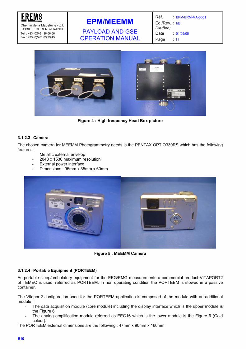
3.1.2.3 Camera
The chosen camera for MEEMM Photogrammetry needs is the PENTAX OPTIO330RS which has the following features:
- Metallic external envelop - 2048 x 1536 maximum resolution - External power interface - Dimensions : 95mm x 35mm x 60mm
Figure 5 : MEEMM Camera
3.1.2.4 Portable Equipment (PORTEEM)
As portable sleep/ambulatory equipment for the EEG/EMG measurements a commercial product VITAPORT2 of TEMEC is used, referred as PORTEEM. In non operating condition the PORTEEM is stowed in a passive container. The Vitaport2 configuration used for the PORTEEM application is composed of the module with an additional module :
- The data acquisition module (core module) including the display interface which is the upper module is the Figure 6
- The analog amplification module referred as EEG16 which is the lower module is the Figure 6 (Gold colour).
The PORTEEM external dimensions are the following : 47mm x 90mm x 160mm.

Chemin de la Madeleine - Z.I. 31130 FLOURENS-FRANCE Tél. : +33.(0)5.61.36.06.06 Fax : +33.(0)5.61.83.99.45
EPM/MEEMM PAYLOAD AND GSE
OPERATION MANUAL
Réf. : EPM-ERM-MA-0001 Ed./Rév. : 1/E (Iss./Rev.)
Date : 01/06/05 Page : 12
E10
Figure 6 : Configuration of the PORTEEM
3.1.2.5 Sensors and accessories
3.1.2.5.1 EEG electrode cap The EEG electrode cap for the MEEMM application is :
- Commercial classical gel cap - Electro-cap from Electro-Cap International (ECI - US)
The electrode positions are based on an extension of the 10-20 system. Nevertheless, due to the number of wires for the 128 electrode cap, some distortions are possible compared to the theory. Digitising process will allow to take into account theses distortions (refer to paragraph 4.2.1.3). The Electro Cap is stretched over the subjects head using both hands from the front to the back of the cap in a smooth motion and fastened thanks to a chin strap.

Chemin de la Madeleine - Z.I. 31130 FLOURENS-FRANCE Tél. : +33.(0)5.61.36.06.06 Fax : +33.(0)5.61.83.99.45
EPM/MEEMM PAYLOAD AND GSE
OPERATION MANUAL
Réf. : EPM-ERM-MA-0001 Ed./Rév. : 1/E (Iss./Rev.)
Date : 01/06/05 Page : 13
E10
Figure 7 : 32, 64 and 128 electrode caps For photogrammetry, the cap is equipped with a scale ruler fixed by velcro. A dermatological pen is used to put temporary marker on the subject.
Figure 8 : 128 electrode cap with scale ruller- Pen
Each of the electrode mounts have a hole in the middle and underneath the hole, embedded in the plastic mount, is a small donut-shaped electrode. The electrode is attached to a wire which comes out of the back of the cap. The gel injection in the electrodes of the cap is based on exactly the same method that is used in all clinics for EEG measurements: the gel will be inserted in the electrodes mount holes using a syringe with a blunted needle.
Chemin de la Madeleine - Z.I. 31130 FLOURENS-FRANCE Tél. : +33.(0)5.61.36.06.06 Fax : +33.(0)5.61.83.99.45
EPM/MEEMM PAYLOAD AND GSE
OPERATION MANUAL
Réf. : EPM-ERM-MA-0001 Ed./Rév. : 1/E (Iss./Rev.)
Date : 01/06/05 Page : 14
E10
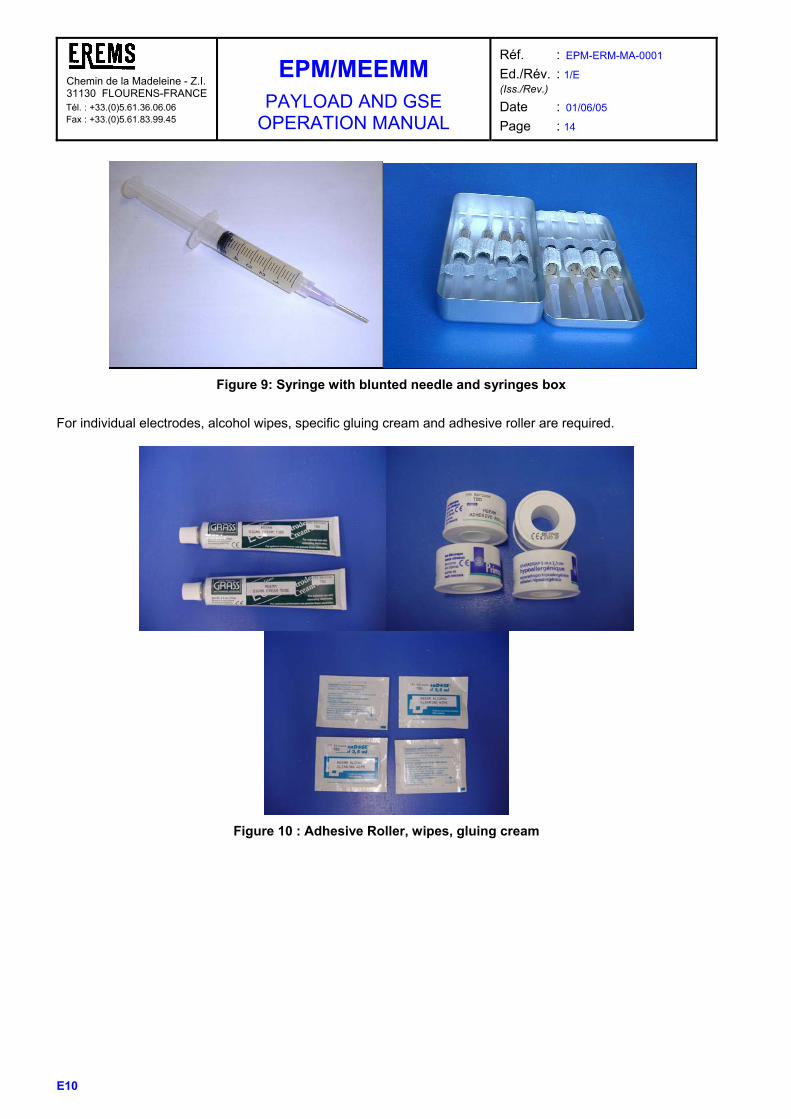
Figure 9: Syringe with blunted needle and syringes box
For individual electrodes, alcohol wipes, specific gluing cream and adhesive roller are required.
Figure 10 : Adhesive Roller, wipes, gluing cream

Chemin de la Madeleine - Z.I. 31130 FLOURENS-FRANCE Tél. : +33.(0)5.61.36.06.06 Fax : +33.(0)5.61.83.99.45
EPM/MEEMM PAYLOAD AND GSE
OPERATION MANUAL
Réf. : EPM-ERM-MA-0001 Ed./Rév. : 1/E (Iss./Rev.)
Date : 01/06/05 Page : 15
E10
3.1.2.5.2 EMG sensors The MEEMM harness for EMG application is based on :
o The use of individual or dual pre-gelified standard surface EMG electrodes o MultibioSensors electrodes
The photo here below shows a zoom on two types of EMG electrodes that can be provided. The snapping parts is integrated within a specific EMG harness (the white plastic interface is suppressed).
Figure 11 : One use surface EMG electrode
Figure 12 : EMG 16 harness
32 EMG pairs and 16 EMG pairs harnesses will be provided. Nevertheless, as the position and the type of each channel depend on the experimental sequence (arm muscles response, finger muscles response, leg, etc......), new harnesses can be required for specific scientific scenario.

Chemin de la Madeleine - Z.I. 31130 FLOURENS-FRANCE Tél. : +33.(0)5.61.36.06.06 Fax : +33.(0)5.61.83.99.45
EPM/MEEMM PAYLOAD AND GSE
OPERATION MANUAL
Réf. : EPM-ERM-MA-0001 Ed./Rév. : 1/E (Iss./Rev.)
Date : 01/06/05 Page : 16
E10
3.1.2.5.3 Ambulatory and sleep sensors The portable acquisition system has to be designed to acquire 16 channels. The number of specific monopolar and bipolar channels depends on the chosen portable device. The Vitaport2 acquisition unit baseline is to use the 16 module configuration including : We plan to use a 16 channel EEG /Polysomnography acquisition system which complies with various types of sensor required for the sleep and ambulatory studies :
- 12 EEG electrodes cap - ECG electrodes - Strain-gauge respiration channel - EMG surface electrodes
Figure 13 : PORTEEM sensors and accessories (Optilink)

Chemin de la Madeleine - Z.I. 31130 FLOURENS-FRANCE Tél. : +33.(0)5.61.36.06.06 Fax : +33.(0)5.61.83.99.45
EPM/MEEMM PAYLOAD AND GSE
OPERATION MANUAL
Réf. : EPM-ERM-MA-0001 Ed./Rév. : 1/E (Iss./Rev.)
Date : 01/06/05 Page : 17
E10
3.1.2.6 GSE
The MEEMM GSE is composed of two main HW/SW sets. The first set is used only for ground sites testing and standalone activities. This set includes :
• MEEMM GSE main box This mechanical box is used to connect the various MEEMM interface to allow check out and MEEMM command in stand alone configuration.
Figure 14 : GSE main box
It also includes the following units : - 28 Vdc power supply This item is a commercial laboratory power supply device : 220V/110V to 28 Vdc. The double power source is required to allow MEEMM stand alone configuration. - Ethernet switch This item is a commercial Ethernet switch equipped with 5 outputs.
• Generator boards integrated in the MEEMM GSE PC
- Trigger and EEG/EMG simulation unit (HW/SW) - RS links simulation unit (HW/SW)
• Air cooling powered by the MEEMM GSE main box
Figure 15 : Air cooling system

Chemin de la Madeleine - Z.I. 31130 FLOURENS-FRANCE Tél. : +33.(0)5.61.36.06.06 Fax : +33.(0)5.61.83.99.45
EPM/MEEMM PAYLOAD AND GSE
OPERATION MANUAL
Réf. : EPM-ERM-MA-0001 Ed./Rév. : 1/E (Iss./Rev.)
Date : 01/06/05 Page : 18
E10
• Commercial standard laptop unit
• GSE Attenuator box This box performs the physical interface between the GSE analog generator interface box and the headboxes inputs. Plugs are used to connect the attenuator box to the headbox input connectors
Figure 16 : GSE Attenuator box and plugs
• GSE analog generator interface box
This box performs the physical interface between the Trigger and EEG/EMG simulation board inserted in the MEEMM GSE PC, the digital interface on the MU front panel and the GSE Attenuator box.
Figure 17 : GSE analog generator interface box
The second set is used both for ground testing and standalone activities and Flight operations support. It includes :
• MEEMM GSE PC including adaptor for MEEMM HD • Various SWs, for which main use or concept are given in this document but reference
information are provided in dedicated documents : - HD formatting SW (refer to RD2 “EPM/MEEMM SW User Manual”) - Photo post processing SW (refer to RD26 “EPM/MEEMM 3D Electrodes Modelling User Manual”) - MMI SW (identical to on board MMI SW) (refer to RD2 “EPM/MEEMM SW User Manual”) - PORTEEM SW (identical to on board SW) (refer to RD23 “Columbus User’s manual”) - Session profile generation SW (refer to RD2 “EPM/MEEMM SW User Manual”)
3.1.3 THE RD24 “EPM/MEEMM DIL” SHOWS WHICH ITEMS ARE PROVIDED WITH THE GSES OF THE DIFFERENT MODELS.

Chemin de la Madeleine - Z.I. 31130 FLOURENS-FRANCE Tél. : +33.(0)5.61.36.06.06 Fax : +33.(0)5.61.83.99.45
EPM/MEEMM PAYLOAD AND GSE
OPERATION MANUAL
Réf. : EPM-ERM-MA-0001 Ed./Rév. : 1/E (Iss./Rev.)
Date : 01/06/05 Page : 19
E10
OPERATIONAL MODES AND ON-BOARD CONTROL This paragraph gives only high level information on the operational modes as most of these modes are transparent for classical on-board operations. Links to reference documents are provided. The on board MMI/CTRL control configuration is the following :
LTU
MEEMMCTRLEPM
SMSC
Science TMserver
Server
EPMCLSW
Server
MEEMM MMI
client
TCL server
client client
client
client
client
All the MEEMM user interface command will be handled by the CLSW (Carrier control Laptop SoftWare) on the LTU, using EPM dedicated interface. For the MEEMM Science Module SW, the different possible states are :
• Check Out • Start-up • Set-up • Nominal • Wait-On-Sync • Test
The list of telecommands authorized for each mode is provided in AD7 “MEEMM TM/TC Data definition “. For the 3 last modes, experiment sub modes are used :
• Idle : MEEMM is waiting for a command • Normal acquisition : normal EEG/EMG data acquisition without recording • Impedance : MEEMM acquires data in impedance testing mode • Recording : MEEMM acquires and store data on hard disk. • Calibration : MEEMM in calibration mode
These modes are detailed in RD17 “EPM/MEEMM SW Architectural Design Document” and RD16 “EPM/MEEMM SW Detailed Design Document”. The commands associated for each mode are provided in RD2 “EPM/MEEMM SW User Manual”.
Chemin de la Madeleine - Z.I. 31130 FLOURENS-FRANCE Tél. : +33.(0)5.61.36.06.06 Fax : +33.(0)5.61.83.99.45
EPM/MEEMM PAYLOAD AND GSE
OPERATION MANUAL
Réf. : EPM-ERM-MA-0001 Ed./Rév. : 1/E (Iss./Rev.)
Date : 01/06/05 Page : 20
E10
3.1.4 RESOURCES, POWER AND THERMAL CHARACTERISTICS
3.1.4.1 Data rate and storage capacity
For MEEMM stationary configurations, the raw EEG/EMG data are stored on a removable hard disk. This storage medium also contains the photo, calibration and impedance files. As discussed in RD18 “EPM/MEEMM Operational Analysis Report”, we assume that typical durations of an experiment scenario are one hour for the low frequency experiments and 20 minutes for high frequency ones. Taking into account these assumptions and that the MEEMM Science Module is equipped with a removable hard disk of 40 Gbytes capacity, the recording capabilities of the MEEMM SM are the following :
Configuration Recording capabilities
128 signals at 2,2 kHz At least 10 sessions
32 signals at 40 kHz At least 8 sessions To satisfy the same requirements for the ambulatory equipment with a typical duration of an experiment scenario of 8 hours, the PORTEEM is equipped with a compact flash disk (SanDisk, 256 MB capacity) inserted in a standard compact flash dish adapter to be compatible with PCMCIA ATA cards. Taking into account these assumptions, the recording capabilities of the PORTEEM are the following :
Configuration Recording capabilities
Ambulatory 16 signals at 200 Hz At least 1 session The operations linked to hard disk exchange are described in paragraph 4.2. For data down-linking, the offered MEEMM capabilities are the following :
• Telescience operation during an acquisition session : o The MEEMM transmits to the EPM carrier the same experiment data as those displayed on
the laptop o This transfer is performed using the Ethernet link between the MEEMM main unit and the
EPM carrier o We can only guarantee the near real time performances for the transmission from the
MEEMM to the EPM. o The associated display environment required by the MEEMM GSE display SW shall be
provided by the EPM carrier and EPM GSE. o Complete raw experiment data can not be transmitted during the experiment session.
• Experiment data transfer after an acquisition session
o The MEEMM internal hard disk is used in playback mode and the raw experiment data are transferred to the EPM carrier using the Ethernet link
o Based on a maximum MEEMM/EPM transfer rate of 1 Mbit/s (LAN capabilities according to AD3), splitted between packets for ground and packets for MMI : o For a 128 electrode session at 2,2 kHz sampling frequency, the transfer to the EPM
requires at least 4,5 hours for a 1 hour acquisition session. o For a 32 electrode session at 20 kHz sampling frequency, the transfer to the EPM
requires at least 3 hours for a 20 minute acquisition session. o To obtain the global downlinking duration from MEEMM to ground, the EPM/ground HRDL
capabilities have also to be taken into account. At the moment, it appears that the capabilities of this EPM/ground HRDL are quite similar to those of the MEEMM/EPM link, resulting in similar required duration.

Chemin de la Madeleine - Z.I. 31130 FLOURENS-FRANCE Tél. : +33.(0)5.61.36.06.06 Fax : +33.(0)5.61.83.99.45
EPM/MEEMM PAYLOAD AND GSE
OPERATION MANUAL
Réf. : EPM-ERM-MA-0001 Ed./Rév. : 1/E (Iss./Rev.)
Date : 01/06/05 Page : 21
E10
3.1.4.2 Consumables
The specific Increment stowage items are very dependent of the scientific sessions that will be carried. This following average budget is related to consumables items required for a specific increment based on the following assumptions (refer to RD18 “EPM/MEEMM Operational Analysis Report”) :
- 2 x ambulatory/sleep sessions - 2 x 32-EEG low frequency sessions - 1 x 32-EEG high frequency sessions - 2 x 32-EMG high frequency sessions (up to 64 surface electrodes) - 3 x 64-EEG low frequency sessions - 3 x 128-EEG low frequency sessions
This budget is based on FM measurements.
Mass (g) Dimensions (mm) Part No
Classification / Item Name Qty
per Item total Height/Ø Width Depth
EEG Electrode Caps
12.30.14.0 12 EEG electrode positioner 3 130 390 50 120 200
12.30.13.0 32 EEG electrode positioner 3 200 600 50 140 200
12.30.12.0 64 EEG electrode positioner 3 360 1 080 50 220 200
12.30.11.0 128 EEG electrode positioner 3 560 1 680 50 300 200
EMG Electrodes
12.30.21.0 EMG Single Electrode (set of 6 electrodes) 16 11 176 5 102 126
12.30.22.0 EMG Dual Electrodes (set of 2 pairs of electrodes) 32 7 224 5 112 126
Consumables
12.40.72.0 Syringes 56 12 672 30 17 175
12.40.71.0 Syringes Box 7 135 945 36 95 185
12.40.40.0 Alcohol Cleaning Wipe 20 5 100 2 60 80
12.40.73.0 Adhesive Roller 1 19 15 32 52 52
12.40.74.0 Signa Cream Tube 1 102 102 30 45 175
12.40.80.0 Dermatological Pen 2 12 24 10 10 150
12.40.60.0 PORTEEM Batteries 8 25 200 50 14 14
12.40.10.0 Hard Disk 5 287 1 435 20 84 160
12.40.90.0 Scale Ruler 1 7 7 20 5 5
Table 3 : Temporary stowage items volume and mass budgets
Note : The number of EEG caps can be decreased if the information of required sizes is known for each increment.

Chemin de la Madeleine - Z.I. 31130 FLOURENS-FRANCE Tél. : +33.(0)5.61.36.06.06 Fax : +33.(0)5.61.83.99.45
EPM/MEEMM PAYLOAD AND GSE
OPERATION MANUAL
Réf. : EPM-ERM-MA-0001 Ed./Rév. : 1/E (Iss./Rev.)
Date : 01/06/05 Page : 22
E10
3.1.4.3 Power budget
The MEEMM required primary nominal voltage is 28 VDC available at the SAC rear panel. On this bus, the operating current is from 0,2A to 4,8A (10 ms max before circuit breaker action). Additionally, two power ON/OFF manual switch (Headboxes and Camera) which enable the MEEMM to power when required the associated deployable devices are provided on the MEEMM Main Unit front panel.. These switches are equipped with a green LED indicating power presence on the Headboxes and Camera power front panel connectors. The camera branch is protected thanks to a specific limiter / circuit breaker circuit with the following characteristics :
o VNom : 4,5V o INom : 1 A o IMax : 1,5 INom
The isolated / headboxes branch is protected thanks to a specific limiter / circuit breaker circuit with the following characteristics :
o VNom : +/- 5V o INom : 0,25 to 0,3 A o IMax : 1,5 INom
3.1.4.4 Power consumption
This budget is based on FM measurements.
Configuration
Power consumption
(typical)
Main Unit +one LHB
60.5 W
Main Unit + two LHBs
63 W
Main Unit + HHB
59 W
Main unit + Camera 39 W
Main unit (no connected deployable items – Stand by
mode)
28W to 36 W
Table 4 : MEEMM various items power consumption

Chemin de la Madeleine - Z.I. 31130 FLOURENS-FRANCE Tél. : +33.(0)5.61.36.06.06 Fax : +33.(0)5.61.83.99.45
EPM/MEEMM PAYLOAD AND GSE
OPERATION MANUAL
Réf. : EPM-ERM-MA-0001 Ed./Rév. : 1/E (Iss./Rev.)
Date : 01/06/05 Page : 23
E10
3.1.4.5 Thermal budget
Two types of items can be considered:
1. The Main Unit enclosed in a 4 PU Active Container dissipating mainly in the ACS (EPM Air Control System)
2. Items resulting in Heat dissipation in the Cabin The power dissipated by those items are:
ITEMS POWER DISSIPATION
MAIN UNIT
for which front panel dissipation in cabin is:
per convexion
per radiation
58 W (LHB configuration)
< 1.5 W (1)
< 7.5 W (1)
DEPLOYABLE ITEMS
HHB
LHB 1
LHB 2
Camera
Porteem
1.2 W
2,5 W
2,5 W
4 W
0.8 W (batteries)
The resulting thermal budget for the main MEEMM configurations is the following :
Configuration
Total Power dissipation
Including the following
Power dissipation In Cabin (1)
Main Unit +one LHB
60.5 W
11,5 W
Main Unit + two LHBs
63 W
14 W
Main Unit + HHB
59 W
10 W
Main unit + Camera 39 W 9 W
Main unit (no connected
deployable items – Stand by mode)
28 to 36 W
5 W
(1) in worst case in regard of the dissipation in the cabin (i.e 18°C for the cabin air and cabin environment temperatures, warm temperatures for other SAC I/F (ACS, panels…) ) Tables and graphs showing the expected thermal behaviour of the payload in normal and worst case conditions are given in RD18 “EPM/MEEMM Thermal Analysis Report”.
Chemin de la Madeleine - Z.I. 31130 FLOURENS-FRANCE Tél. : +33.(0)5.61.36.06.06 Fax : +33.(0)5.61.83.99.45
EPM/MEEMM PAYLOAD AND GSE
OPERATION MANUAL
Réf. : EPM-ERM-MA-0001 Ed./Rév. : 1/E (Iss./Rev.)
Date : 01/06/05 Page : 24
E10
3.1.5 TELEMETRY AND TELECOMMAND DATA The commands are received by MEEMM Main Unit from the RS485 interface nominal or redundant. They are processed by the MEEMM SPVR-SW. The House-Keeping data are managed by the SPVR SW and sent periodically to the EPM Carrier via the RS 485 interface (nominal or redundant). The detailed description of these telecommand and telemetry data (format, parameter description, sampling rates, design limits, data validity criteria) are given in AD7 “MEEMM TM/TC Data definition”. Three types of critical housekeeping data are directly transmitted to the EPM without supervisor SW processing:
- 2 analog output lines, on the rear panel data connector, sent directly to the EPM/Carrier Control, the Primary Voltage and the Primary Current.
- 2 temperature measurements transmitted to the EPM using dedicated thermistor lines (PWR block, Front Panel)
- 3 digital O are used, one for the supervisor unit alert status (representative of any fault detection and isolation), the second for the MEEMM secondary power status, the last one for the MEEMM main circuit breaker status.
Chemin de la Madeleine - Z.I. 31130 FLOURENS-FRANCE Tél. : +33.(0)5.61.36.06.06 Fax : +33.(0)5.61.83.99.45
EPM/MEEMM PAYLOAD AND GSE
OPERATION MANUAL
Réf. : EPM-ERM-MA-0001 Ed./Rév. : 1/E (Iss./Rev.)
Date : 01/06/05 Page : 25
E10
3.2 DETAILED DESCRIPTION
3.2.1 HARDWARE ITEMS – GLOBAL VIEW The tables hereafter describe the different items associated with MEEMM hardware and show their main functions.
3.2.1.1 Stationary mode
3.2.1.1.1 Items and Electronics circuits
Element Item Function
Cap
• Electrode cap (including harnesses) on the astronaut head Up to 128 electrodes dedicated to both EEG and EP recording.
• Associated reference electrode
• Associated ground electrode
Consumables
• Conductive gel
• Syringes and blunted needles
• Cleaning wipes
• Adhesive tape
EEG/EP electrode cap set
Accessories • Dermatological Pen
• Scale ruler
Element Item Function
EEG32 Low Frequency Headbox harness (x4)
• Adaptor to link the EEG cap (by group of 32 EEG electrodes) to low frequency headbox
Adaptor to link the EEG caps to
headboxes EEG32 High Frequency
Headbox harness
• Adaptor to link the EEG cap (by group of 32 EEG electrodes) to high frequency headbox
Element Item Function
Electrodes • EMG surface electrodes Set of surface
EMG electrodes Consumables
• Cleaning wipes
• Spare EMG surface electrodes
Element Item Function
EMG16 Headbox Harness • Harness to link 16 pairs of EMG electrodes to high or low frequency headbox
Harness set to link EMG
electrodes to headboxes EMG32 Headbox Harness • Harness to link 32 pairs of EMG electrodes to
high or low frequency headbox

Chemin de la Madeleine - Z.I. 31130 FLOURENS-FRANCE Tél. : +33.(0)5.61.36.06.06 Fax : +33.(0)5.61.83.99.45
EPM/MEEMM PAYLOAD AND GSE
OPERATION MANUAL
Réf. : EPM-ERM-MA-0001 Ed./Rév. : 1/E (Iss./Rev.)
Date : 01/06/05 Page : 26
E10
Element Item Function
64 channel low frequency
headbox 1
EEG/EP/EMG low conditioning/ADC board
(x2)
• Protection + Pre-amplifiers + amplifiers (32 bipolar channels)
• Conversion to digital data 22 bits
• 1 serial digital data output
Element Item Function
64 channel low frequency
headbox 2
EEG/EP/EMG low conditioning/ADC board
(x2)
• Protection + Pre-amplifiers + amplifiers (32 bipolar channels)
• Conversion to digital data 22 bits
• 1 serial digital data output
Element Item Function
Low Frequency Headbox DATA1 Harness
• Low channel data transmission from the low frequency headbox to the main unit when a single LHB is used
Headbox POWER1 Harness • Power supply lines between the main unit
and the low or high frequency headbox when a single headbox is used
Low Frequency Headbox DATA2 Harness
• Low channel data transmission from the low frequency headbox to the main unit when both headboxes are used
Headbox POWER2 Harness • Power supply lines between the main unit
and the low or high frequency headbox when two headboxes are used
High Frequency Headbox DATA Harness
• High channel data transmission from the high frequency headbox to the main unit
Headbox Calibration Plug (x4)
• Plug required for LHB and HHB acquisition channels calibration
Software Download Plug • Plug required for SPVR SW download, to be connected on the MU front panel
Harness set to link headboxes to
the main unit
Plugs
RS485 Redundant Plug • Plug required to use the redundant RS485
interface, to be connected on the MU front panel
Element Item Function
EEG/EP/EMG high first stage conditioning board
(x4)
• Protection + differential pre-amplifiers (8 bipolar channels)
• 8 analog data outputs High frequency headbox
Power supply regulation board
• Regulation function of the secondary voltages for the whole high frequency headbox

Chemin de la Madeleine - Z.I. 31130 FLOURENS-FRANCE Tél. : +33.(0)5.61.36.06.06 Fax : +33.(0)5.61.83.99.45
EPM/MEEMM PAYLOAD AND GSE
OPERATION MANUAL
Réf. : EPM-ERM-MA-0001 Ed./Rév. : 1/E (Iss./Rev.)
Date : 01/06/05 Page : 27
E10
Element Item Function
4 DC/DC Converter boards
• Bus Filter
• Power Conversion, secondary voltages delivery (isolated, unregulated or regulated according to supplied function)
• Current limiter/circuit breaker
EEG/EP/EMG high conditioning board
(x4)
• 8 EEG/EMG amplifiers channels
• Conversion to digital data 24 bits
• 2 serial digital data outputs
Adaptor board
• Low frequency headbox signal isolation stages
• 5V/3,3V DSP interface adaptor
• Low and high frequency channel multiplexing in front of the DSP unit
• Impedance/calibration source
Synchro board • Acquisition of external analog sources
• Acquisition chains clock and control signal generation
DSP board
(x2)
• Acquisition of digital trigger events
• Data file formatting, header generation
CPU board
• System management
• Communication with SMSC via Ethernet link
• Data transfer to/from removable hard disk
• Acquisition chains configuration
Storage unit • Removable hard disk to perform both on line
recording and mass storage functions
• Interface with CPU board
Supervisor unit
(2 boards)
• Time synchronisation with SMSC
• Acquisition internal temperatures
• Acquisition of monitoring parameters (secondary voltages, current…)
• RS485 and testlink interface with SMSC
Main unit
Up and down Consumables • Removable harddisk
Element Item Function
Dedicated MEEMM Camera • Measurement of position of electrodes
Harness Camera • Power supply transmission from the main unit to the camera
Digitizing unit
Storage unit • Compact flashdisk and associated adaptor

Chemin de la Madeleine - Z.I. 31130 FLOURENS-FRANCE Tél. : +33.(0)5.61.36.06.06 Fax : +33.(0)5.61.83.99.45
EPM/MEEMM PAYLOAD AND GSE
OPERATION MANUAL
Réf. : EPM-ERM-MA-0001 Ed./Rév. : 1/E (Iss./Rev.)
Date : 01/06/05 Page : 28
E10
3.2.1.1.2 Interface functions Three major interfaces are experiment dedicated :
• Headboxes EEG/EMG inputs • Digital trigger input • Analog sources input
Headboxes EEG/EMG inputs
• Differential inputs (refer to RD27 “Interface Control Document”.for connector pin out and interface scheme)
• LHB - Maximum Input range : 0,8 mVpp to 30 mVpp (according to programmed gain : 150, 500, 2500 or 7000)
• HHB - Maximum Input range : 1,4 mVpp to 28 mVpp (according to programmed gain : 170, 500, 1600 and 3800)
Digital trigger input
• Input amplitude : TTL levels • Rising or falling edge detection is SW programmable • The high or low level duration shall be upper than 5 x 1/ Fs and 2 ms • Refer to RD27 “Interface Control Document”.for connector pin out and interface scheme
Analog sources input
• Maximum input amplitude : +/- 10 V pp • Refer to RD27 “Interface Control Document”.for connector pin out and interface scheme

Chemin de la Madeleine - Z.I. 31130 FLOURENS-FRANCE Tél. : +33.(0)5.61.36.06.06 Fax : +33.(0)5.61.83.99.45
EPM/MEEMM PAYLOAD AND GSE
OPERATION MANUAL
Réf. : EPM-ERM-MA-0001 Ed./Rév. : 1/E (Iss./Rev.)
Date : 01/06/05 Page : 29
E10
3.2.1.2 Ambulatory and sleep mode
3.2.1.2.1 Items and Electronics circuits
Element Item Function
Sensors • EEG/EMG and other sensors (up to 16)
Consumables
• Spare associated sensors
• Cleaning wipes
• Sensor fixation set
• Batteries for the processing unit
Harness PORTEEM • Harness to link ambulatory &sleep sensors to the portable processing unit
Processing unit • Experiment data acquisition
PORTEEM
Up and down Consumables • Compact flashdisk and associated adaptor
3.2.1.2.2 Interface functions The PORTEEM equipment has a single type of operational interfaces : the sensors input one. The use of a PORTEEM dedicated interface unit – the patchpanel – limits the operator possible choices to the selection of programmed gain within the acquisition chain. This programming is done thanks to a dedicated commercial SW that will be part both of the MEEMM on board SWs (implemented on the EPM LTU) and of the GSE deliveries (referred as PORTEEM “Columbus” SW).

Chemin de la Madeleine - Z.I. 31130 FLOURENS-FRANCE Tél. : +33.(0)5.61.36.06.06 Fax : +33.(0)5.61.83.99.45
EPM/MEEMM PAYLOAD AND GSE
OPERATION MANUAL
Réf. : EPM-ERM-MA-0001 Ed./Rév. : 1/E (Iss./Rev.)
Date : 01/06/05 Page : 30
E10
3.2.2 SOFTWARE ITEMS
The definition of the MEEMM computer software items is presented on Figure 18. In grey are shown the SW items that are parts of MEEMM delivery.
ON GROUND
Processing SW
GSE SW
Scientistsystem
Scientistsystem
ON BOARD
MEEMM main unit
Remo-vableHD
DSP SW
SPVR SW
CTRL SW
Groundstorage
FacilityControl
ComputerSW
EPM Facility
EPM LTU
MEEMMMMI SW
EPM carrierControl SW
BOOTSW
DRIVER
PORTEEM SW
Figure 18 : On board / on ground SW definition
The MEEMM computer software items include :
Abbreviation Role Runs on
CTRL/DSP SW
DRIVER
Control SW (CPU) and Head box Data Acquisition SW (DSP)
CPU board and DSP boards
SPVR SW
BOOT SW
Supervision and House Keeping Supervisor Board micro-controller
MMI SW Man Machines Interface EPM LTU
GSE SW MEEMM Ground support SW EPM carrier GSE
PORTEEM SW
(not represented on the scheme on EPM LTU)
PORTEEM application
Signal quality check before recording
EPM LTU
EPM carrier GSE

Chemin de la Madeleine - Z.I. 31130 FLOURENS-FRANCE Tél. : +33.(0)5.61.36.06.06 Fax : +33.(0)5.61.83.99.45
EPM/MEEMM PAYLOAD AND GSE
OPERATION MANUAL
Réf. : EPM-ERM-MA-0001 Ed./Rév. : 1/E (Iss./Rev.)
Date : 01/06/05 Page : 31
E10
The DSP SW acquires data from the heabox and read triggers information from the trigger connector. The CTRL SW gets these data. The data are stored on disk, and processed to be displayed on MMI SW and sent on ground if tele operation is required. The SPVR SW receives TC from the carrier. TC addressed to CTRL SW are forwarded. It also acquires current, temperature information and fulfills the HK frame. Additionally, the HK frame is completed with information coming from CTRL SW. The MMI SW receives data to be displayed and screen layout definition. The data coming from PORTEEM and digital camera can be read on the LTU using LTU flash file reader and sent back to the CTRL SW using EPM services. The SW components are detailed in RD17 “EPM/MEEMM SW Architectural and Detailed Design Document” The SW commands and the sequences of mode (except the SPVR SW) are described in a dedicated User Manual RD2 “EPM/MEEMM SW User Manual . The SPVR SW commands are given in AD7 “MEEMM TM/TC Data definition”. Additionally, in paragraph 4.3, an example of various MMI displays corresponding to a typical EEG scenario is given.
The PORTEEM SW is described in RD23 “Columbus User’s manual”.
3.2.3 GSE ITEMS This paragraph describes the complete MEEMM GSE configuration. According to specific model needs, the GSE can include a subset of the following items (refer to RD24 “Delivery Item List”).
3.2.3.1 Items and electronics circuits
3.2.3.1.1 MEEMM GSE main box The GSE main box internal components are the followings :
Qty Description Reference Manufacturer
1 Box Propac 3U63FP376 Ref appro:10850-021 SCHROFF
4 Box element Profil avant 63F Ref appro: 30818-094 SCHROFF
1 Box element Vis fixation Ref appro: 21101-416 SCHROFF
1 Box element Face avant 3U63F Ref appro: 20850-136 SCHROFF
1 Box element Panneaux arrière Ref appro: 20850-366 SCHROFF
1 28V Power supply VEGA450V402YJT (V4QST 28B 5S) LAMBDA
1 Ethernet Switch PEAB-SW5M PEABIRD
1 5V Power supply ZWS5-5 LAMBDA 1 1 Status board CDL/1.1721 001/ERE 1/A EREMS
Table 5 : GSE main box internal components

Chemin de la Madeleine - Z.I. 31130 FLOURENS-FRANCE Tél. : +33.(0)5.61.36.06.06 Fax : +33.(0)5.61.83.99.45
EPM/MEEMM PAYLOAD AND GSE
OPERATION MANUAL
Réf. : EPM-ERM-MA-0001 Ed./Rév. : 1/E (Iss./Rev.)
Date : 01/06/05 Page : 32
E10
The GSE main box front panel components are the followings :
Test Bits
1 2 3 4 5
ANALOG
T1 T2 U I 28VAncillary
MEEMM GSESM address
10
1 2 3 4
Digital
RemoteON/OFF
PowerStatus
SupervisorStatus
BreakerStatus
REMOTEONOFF
DGND
J5Test BitsTo Test link
J6RS 422To Test link EREMS
Qty Description MEEMM use 1 4 Switches Dip 8 SM address positioning
1 Switch 5636 from APEM Remote ON/OFF
1 Sub-D 9 S J5 Test Bits 1 Sub-D 15 S J6 RS422 Test Link 3 Green Led Digital I/O indicator (Remote,Power, SVPR) 1 Red Led Digital I/O indicator (Breaker trip status)
20 2mm Banana socket (panel isolated)
Test points for - Digital I/O (1,2,3,4)
- Test bits (1,2,3,4,5,DGND) - Analog ( T1 (PWR block)/T2 (Front panel)/U/I/Ancillary and
associated return))
Table 6 : GSE main box front panel components
The GSE main box rear panel components are the followings : Qty Description MEEMM use
1 J1 Sub-D 50S MEEMM Data connector DPKA 131
1 J2 Sub-D 50P GSE PC Acksys (RS links simulation unit) connector (Sub-D HD 62pts)
1 J3 Sub-D 15P
GSE PC Acksys (RS links simulation unit) connector (Sub-D HD 62pts)
1 J4 Sub-D 9S
Cooling system
3 4mm Banana socket (panel isolated) For MEEMM Power connector DPKA
1 Shaffner Main switch 1 Ethernet switch access MEEMM LAN
Table 7 : GSE main box rear panel components

Chemin de la Madeleine - Z.I. 31130 FLOURENS-FRANCE Tél. : +33.(0)5.61.36.06.06 Fax : +33.(0)5.61.83.99.45
EPM/MEEMM PAYLOAD AND GSE
OPERATION MANUAL
Réf. : EPM-ERM-MA-0001 Ed./Rév. : 1/E (Iss./Rev.)
Date : 01/06/05 Page : 33
E10
3.2.3.1.2 MEEMM GSE PC The GSE PC internal components are the followings (except classical PC components): Qty Description Reference Manufacturer
1 Analog generator board PCI-6711 National Instruments
1 RS links generator 8RSPCI-400 Acksys
3.2.3.1.3 MEEMM GSE attenuator box This box is manufactured by EREMS and includes :
- a 80 dB attenuator based on resistors. - A 1 to 3 BNC distribution of the analog signal
3.2.3.1.4 MEEMM GSE analog generator interface box This box is built from a commercial equipment : National Instruments BNC-2110.
3.2.3.2 Interface functions
3.2.3.2.1 MEEMM GSE main box The interfaces are provided in paragraph 3.2.3.1.1. Refer to RD27 “Interface Control Document”.for connector pin out
3.2.3.2.2 MEEMM GSE PC Analog generator board : Dedicated NI board connector (Refer to RD27 “Interface Control Document”.for connector pin out) RS links generator : 62 points SUBD connector (Refer to RD27 “Interface Control Document”.for connector pin out) Adaptor for MEEMM HD : 37 points SUBD connector (Refer to RD27 “Interface Control Document”.for connector pin out)
3.2.3.2.3 MEEMM GSE attenuator box Inputs : BNC connector Outputs : 3 BNC interfaces and 12 2mm sockets (+, -, GND)
3.2.3.2.4 MEEMM GSE analog generator interface box Inputs : Dedicated NI board connector (Refer to RD27 “Interface Control Document”.for connector pin out) Outputs : DAC0 OUT to DAC03 OUT BNC interface and Digital output TTL SUBD 25 (Refer to RD27 “Interface Control Document”.for connector pin out)

Chemin de la Madeleine - Z.I. 31130 FLOURENS-FRANCE Tél. : +33.(0)5.61.36.06.06 Fax : +33.(0)5.61.83.99.45
EPM/MEEMM PAYLOAD AND GSE
OPERATION MANUAL
Réf. : EPM-ERM-MA-0001 Ed./Rév. : 1/E (Iss./Rev.)
Date : 01/06/05 Page : 34
E10
4 OPERATING INSTRUCTIONS
4.1 MEEMM EXPERIMENT SCENARIOS
4.1.1 GENERAL The types of experiments are very different one from the other on the configuration which is required, e.g.: Sleep & Ambulatory studies need a portable unit, brain stem are carried with only one electrode fixed on top of the skull, long latencies are carried with up to 128 electrodes but with a much lower bandwidth, etc... Those various types of experiments are possible with MEEMM thanks to its modularity of equipments which allow the following configurations (refer to RD18 “EPM/MEEMM Operational Analysis Report”) :
Scenario
Characteristics Average number of sessions per increment
1 UP TO 64 CHANNELSBW: 0.01 HZ TO 580 HZ (bipolar channels at headbox input interface)
5 sessions/increment
1/A Middle/long latency EP on 32 channels
2
1/B Middle/long latency EP on 64 channels
3
1/C Raw EEG on 32 channels 0 (1)
1/D Surface EMG on up to 32 channels (64 electrodes)
0 (2)
2 128 CHANNELSBW: 0.01 HZ TO 580 HZ
(bipolar channels at headbox input interface)
3 session/increment
2/A Middle/long latency EP on 128 channels
3
3 32 CHANNELSBW: 1 HZ TO 10 KHZ
(bipolar channels at headbox input interface)
3 sessions/increment
3/A Short/middle latency EP on 1 to 32 channels
1
3/B Surface EMG on 32 channels (64 electrodes)
2
4 16 channels Sleep & ambulatory 2 sessions/increment
4/A 16 channels Sleep & ambulatory 2
Table 8 : MEEMM experiment scenarios
(1) Raw EEG without stimuli will probably be acquired most of the time with using the PORTEEM (configuration 4)
(2) Surface EMG will probably be acquired most of the time with using the HHB (configuration 3) The choice between those different modes will be made by :

Chemin de la Madeleine - Z.I. 31130 FLOURENS-FRANCE Tél. : +33.(0)5.61.36.06.06 Fax : +33.(0)5.61.83.99.45
EPM/MEEMM PAYLOAD AND GSE
OPERATION MANUAL
Réf. : EPM-ERM-MA-0001 Ed./Rév. : 1/E (Iss./Rev.)
Date : 01/06/05 Page : 35
E10
- The selection of the appropriate hardware by the operator - The configuration, or the choice of the profile file, by operator of the MEEMM through the Man
Machine Interface Software Other modes could be possible with MEEMM equipments, especially some combinations between the number of EEG/EP and of EMGs, for instance:
• simultaneous acquisition with the LHBs of 96 EEG channels with 32 EMG channels • or simultaneous acquisition with the LHBs of 64 EEG with 32 EMG or • or simultaneous acquisition with the HHB of 16 EEG with 16 EMG channels • etc.
Many possibilities are thinkable: they have not been planned here as each of them would require additional resources in terms of sensor sets and harnesses. Notes:
1) The combination consisting in using simultaneously both the HHB and the LHB(s) is not allowed.
2) The MEEMM SM has to be re-initialised (Main ON/OFF switch or RESET button) when changing of acquisition configuration : either LHB or HHB acquisition, either analog channels acquisition or not….)
4.1.2 HARDWARE ITEMS – SELECTION ACCORDING TO RMS For each configuration & mode described in Table 8 : MEEMM experiment scenarios, the required items for one session are shown in the following tables :
Chemin de la Madeleine - Z.I.31130 FLOURENS – France Tél. : +33.(0)5.61.36.06.06 Fax : +33.(0)5.61.83.99.45 Web : www.erems.fr
EPM/MEEMM PAYLOAD AND GSE OPERATION
MANUAL
Réf. : EPM-ERM-MA-0001 Ed./Rév. : 1/E (Iss./Rev.)
Date : 01/06/05 Page : 36
E10
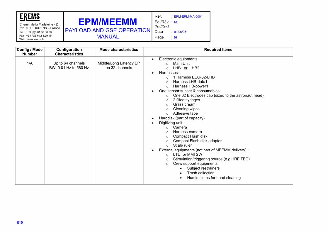
Config / Mode Number
Configuration Characteristics
Mode characteristics Required Items
1/A
Up to 64 channels
BW: 0.01 Hz to 580 Hz
Middle/Long Latency EP
on 32 channels
• Electronic equipments: o Main Unit o LHB1 or LHB2
• Harnesses: o 1 Harness EEG-32-LHB o Harness LHB-data1 o Harness HB-power1
• One sensor subset & consumables: o One 32 Electrodes cap (sized to the astronaut head) o 2 filled syringes o Grass cream o Cleaning wipes o Adhesive tape
• Harddisk (part of capacity) • Digitizing unit:
o Camera o Harness-camera o Compact Flash disk o Compact Flash disk adaptor o Scale ruler
• External equipments (not part of MEEMM delivery): o LTU for MMI SW o Stimulation/triggering source (e.g HRF TBC) o Crew support equipments
• Subject restrainers • Trash collection • Humid cloths for head cleaning
Chemin de la Madeleine - Z.I.31130 FLOURENS – France Tél. : +33.(0)5.61.36.06.06 Fax : +33.(0)5.61.83.99.45 Web : www.erems.fr
EPM/MEEMM PAYLOAD AND GSE OPERATION
MANUAL
Réf. : EPM-ERM-MA-0001 Ed./Rév. : 1/E (Iss./Rev.)
Date : 01/06/05 Page : 37
E10
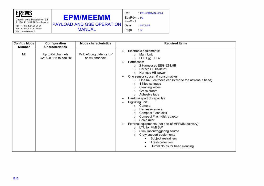
Config / Mode
Number Configuration
Characteristics Mode characteristics Required Items
1/B
Up to 64 channels
BW: 0.01 Hz to 580 Hz
Middle/Long Latency EP
on 64 channels
• Electronic equipments: o Main Unit o LHB1 or LHB2
• Harnesses: o 2 Harnesses EEG-32-LHB o Harness LHB-data1 o Harness HB-power1
• One sensor subset & consumables: o One 64 Electrodes cap (sized to the astronaut head) o 4 filled syringes o Cleaning wipes o Grass cream o Adhesive tape
• Harddisk (part of capacity) • Digitizing unit:
o Camera o Harness-camera o Compact Flash disk o Compact Flash disk adaptor o Scale ruler
• External equipments (not part of MEEMM delivery): o LTU for MMI SW o Stimulation/triggering source o Crew support equipments
• Subject restrainers • Trash collection • Humid cloths for head cleaning
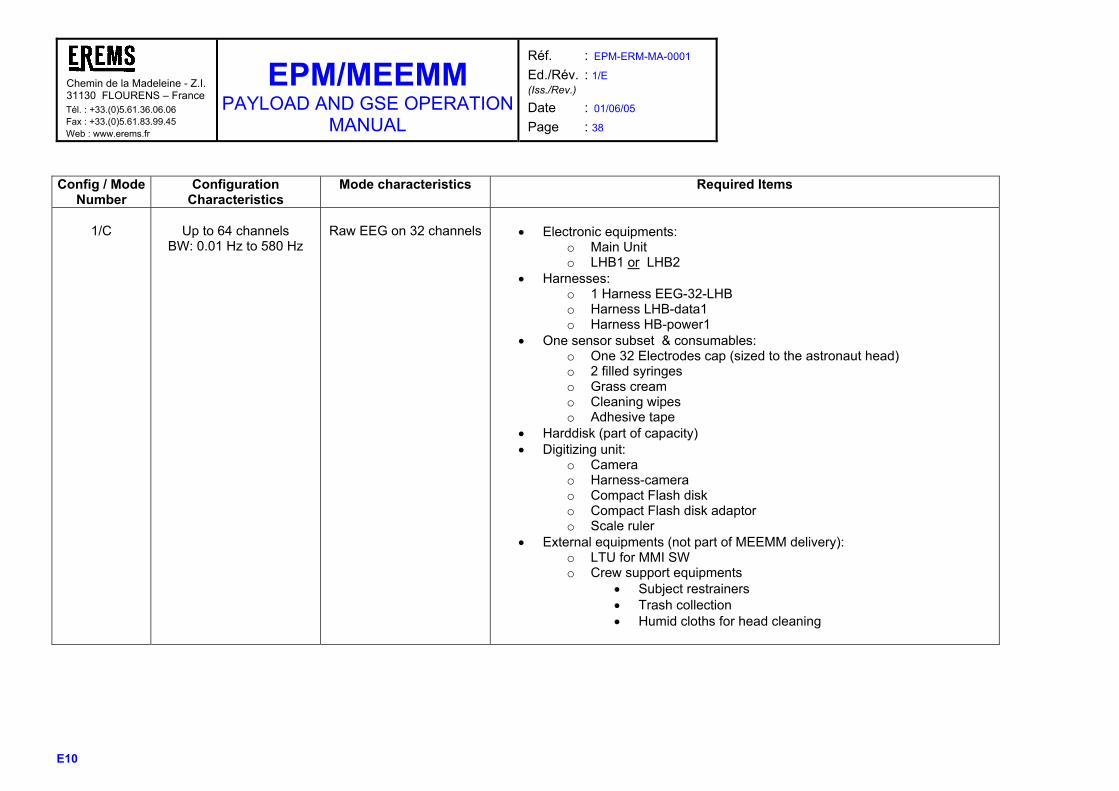
Chemin de la Madeleine - Z.I.31130 FLOURENS – France Tél. : +33.(0)5.61.36.06.06 Fax : +33.(0)5.61.83.99.45 Web : www.erems.fr
EPM/MEEMM PAYLOAD AND GSE OPERATION
MANUAL
Réf. : EPM-ERM-MA-0001 Ed./Rév. : 1/E (Iss./Rev.)
Date : 01/06/05 Page : 38
E10
Config / Mode
Number Configuration
Characteristics Mode characteristics Required Items
1/C
Up to 64 channels
BW: 0.01 Hz to 580 Hz
Raw EEG on 32 channels
• Electronic equipments:
o Main Unit o LHB1 or LHB2
• Harnesses: o 1 Harness EEG-32-LHB o Harness LHB-data1 o Harness HB-power1
• One sensor subset & consumables: o One 32 Electrodes cap (sized to the astronaut head) o 2 filled syringes o Grass cream o Cleaning wipes o Adhesive tape
• Harddisk (part of capacity) • Digitizing unit:
o Camera o Harness-camera o Compact Flash disk o Compact Flash disk adaptor o Scale ruler
• External equipments (not part of MEEMM delivery): o LTU for MMI SW o Crew support equipments
• Subject restrainers • Trash collection • Humid cloths for head cleaning

Chemin de la Madeleine - Z.I.31130 FLOURENS – France Tél. : +33.(0)5.61.36.06.06 Fax : +33.(0)5.61.83.99.45 Web : www.erems.fr
EPM/MEEMM PAYLOAD AND GSE OPERATION
MANUAL
Réf. : EPM-ERM-MA-0001 Ed./Rév. : 1/E (Iss./Rev.)
Date : 01/06/05 Page : 39
E10
Config / Mode
Number Configuration
Characteristics Mode characteristics Required Items
1/D
Up to 64 channels
BW: 0.01 Hz to 580 Hz
Surface EMG on up to 32 channels (64 electrodes)
• Electronic equipments:
o Main Unit o LHB1 or LHB2
• Harnesses: o 1 Harness EMG-16 or EMG-32 o Harness LHB-data1 o Harness HB-power1
• One sensor subset & consumables: o Up to 32 pairs of one-use snapping electrodes o Cleaning wipes
• Harddisk (part of capacity) • External equipments (not part of MEEMM delivery):
o LTU for MMI SW o Crew support equipments
• Subject restrainers • Trash collection

Chemin de la Madeleine - Z.I.31130 FLOURENS – France Tél. : +33.(0)5.61.36.06.06 Fax : +33.(0)5.61.83.99.45 Web : www.erems.fr
EPM/MEEMM PAYLOAD AND GSE OPERATION
MANUAL
Réf. : EPM-ERM-MA-0001 Ed./Rév. : 1/E (Iss./Rev.)
Date : 01/06/05 Page : 40
E10
Config / Mode
Number Configuration
Characteristics Mode characteristics Required Items
2/A
128 channels
BW: 0.01 Hz to 580 Hz
Middle/Long Latency EP
on 128 channels
• Electronic equipments:
o Main Unit o LHB1 and LHB2
• Harnesses: o 4 Harnesses EEG-32-LHB o Harness LHB-data2 o Harness HB-power2
• One sensor subset & consumables: o One 128 Electrodes cap (sized to the astronaut head) o 8 filled syringes o Grass cream o Cleaning wipes o Adhesive tape
• Harddisk (part of capacity) • Digitizing unit:
o Camera o Harness-camera o Compact Flash disk o Compact Flash disk adaptor o Scale ruler
• External equipments (not part of MEEMM delivery): o LTU for MMI SW o Stimulation/triggering source o Crew support equipments
• Subject restrainers • Trash collection • Humid cloths for head cleaning

Chemin de la Madeleine - Z.I.31130 FLOURENS – France Tél. : +33.(0)5.61.36.06.06 Fax : +33.(0)5.61.83.99.45 Web : www.erems.fr
EPM/MEEMM PAYLOAD AND GSE OPERATION
MANUAL
Réf. : EPM-ERM-MA-0001 Ed./Rév. : 1/E (Iss./Rev.)
Date : 01/06/05 Page : 41
E10
Config / Mode
Number Configuration
Characteristics Mode characteristics Required Items
3/A
32 channels
BW: 1 Hz to 10 kHz
Short/Middle latency EP
on 1 to 32 channels
• Electronic equipments:
o Main Unit o HHB
• Harnesses: o 1 Harness EEG-32-HHB o Harness HHB-data o Harness HB-power1
• One sensor subset & consumables: o One 32 Electrodes cap sized to the astronaut head (1) o 2 filled syringes o Grass cream o Cleaning wipes o Adhesive tape
• Harddisk (part of capacity) • Digitizing unit:
o Camera o Harness-camera o Compact Flash disk o Compact Flash disk adaptor o Scale ruler
• External equipments (not part of MEEMM delivery): o LTU for MMI SW o Stimulation/triggering source o Crew support equipments
• Subject restrainers • Trash collection • Humid cloths for head cleaning
(1) for short latencies, only one or 2 electrodes are necessary. Nevertheless, in order to avoid complementary fixing materials such as Collodion, we plan to use a complete cap, only the useful electrodes will be filled with gel.
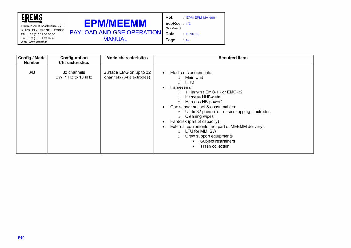
Chemin de la Madeleine - Z.I.31130 FLOURENS – France Tél. : +33.(0)5.61.36.06.06 Fax : +33.(0)5.61.83.99.45 Web : www.erems.fr
EPM/MEEMM PAYLOAD AND GSE OPERATION
MANUAL
Réf. : EPM-ERM-MA-0001 Ed./Rév. : 1/E (Iss./Rev.)
Date : 01/06/05 Page : 42
E10
Config / Mode
Number Configuration
Characteristics Mode characteristics Required Items
3/B
32 channels
BW: 1 Hz to 10 kHz
Surface EMG on up to 32 channels (64 electrodes)
• Electronic equipments:
o Main Unit o HHB
• Harnesses: o 1 Harness EMG-16 or EMG-32 o Harness HHB-data o Harness HB-power1
• One sensor subset & consumables: o Up to 32 pairs of one-use snapping electrodes o Cleaning wipes
• Harddisk (part of capacity) • External equipments (not part of MEEMM delivery):
o LTU for MMI SW o Crew support equipments
• Subject restrainers • Trash collection
Chemin de la Madeleine - Z.I.31130 FLOURENS – France Tél. : +33.(0)5.61.36.06.06 Fax : +33.(0)5.61.83.99.45 Web : www.erems.fr
EPM/MEEMM PAYLOAD AND GSE OPERATION
MANUAL
Réf. : EPM-ERM-MA-0001 Ed./Rév. : 1/E (Iss./Rev.)
Date : 01/06/05 Page : 43
E10
Config / Mode
Number Configuration
Characteristics Mode characteristics Required Items
4/A
16 channels
BW: 0,3 Hz to 150 Hz
Sleep & ambulatory with: • 12 EEG channels
(BW:0,3-70Hz) • 2 EMG channels
(BW:1-150Hz) • 1 ECG channels
(BW:1-150Hz) • 1 strain gauge
respiration channel (BW:0,3-30Hz)
• Electronic equipments:
o PORTEEM • Harnesses:
o Harness PORTEEM • One sensor subset & consumables:
o One 12 Electrodes cap (sized to the astronaut head) o 1 filled syringe o Grass cream o EMG, ECG, strain gauge sensors o Cleaning wipes o Adhesive tape
• Compact Flashdisk and adaptor • 4 AA batteries • External equipments (not part of MEEMM delivery):
o LTU for MMI SW o Crew support equipments
• Equipment restraints for PORTEEM (Bag or Velcro) • Trash collection • Humid cloths for head cleaning

Chemin de la Madeleine - Z.I. 31130 FLOURENS – France Tél. : +33.(0)5.61.36.06.06 Fax : +33.(0)5.61.83.99.45 Web : www.erems.fr
EPM/MEEMM PAYLOAD AND GSE OPERATION
MANUAL
Réf. : EPM-ERM-MA-0001 Ed./Rév. : 1/E (Iss./Rev.)
Date : 01/06/05 Page : 44
E10
4.2 CREW OPERATING TASKS
4.2.1 PRE-INCREMENT, INCREMENT & POST-INCREMENT TASKS
4.2.1.1 Pre-increment tasks
Pre-increment tasks include all the tasks to be performed on ground, with the astronaut, the hardware and the software before launch. This paragraph is divided into 3 parts :
- Crew preparation - HW preparation - SW preparation
4.2.1.1.1 Crew preparation: Tasks Steps Recommendations
Do/Don’t Tips
Choice of the Test Subject
The selection of the subject can not be separated from scientific preliminary tests to check the good behaviour of each subject : - Correct impedances - Low muscle activity - Correct behaviour to scientific stressors
The subject shall not be bald (bad impedance due to the tanned skin). No gel on subject hair
Training to operating of MEEMM
The subject and the operator shall be trained on : - HW connection - Reference points marking - Cap installation (gel injection, impedance checking) - SW interface - Scientific curves appreciation (with help of subject ground proper responses)
The most critical training is the operator one for the cap installation and the gel injection. A minimum of two cap installations are required to get a correct feeling for the gel injection.
Baseline Data Collection on the Test Subject
Subject typical ground responses are required to help the operator to appreciate the subject response on board. During Baseline Data collection : - screen copies have to be done of EEG and EP (if any) responses.
- impedance figures have to be acquired to allow correct configuration on session profile (refer to paragraph 4.2.1.1.3).
Screen copies can be attached to on board procedures in a removable appendix to allow the operator to fix it next to the LTU screen. Some tips can be added on these pages to help the operation to asses the curves : - eyes artefact visualising - noise level compared to selected scale (To be completed with scientists during collection)
Marking of fiducial reference Landmarks (optional, only is
3 reference marks are required for photogrammetry purpose : Nasion, Left preauricular and Right preauricular points.

Chemin de la Madeleine - Z.I. 31130 FLOURENS – France Tél. : +33.(0)5.61.36.06.06 Fax : +33.(0)5.61.83.99.45 Web : www.erems.fr
EPM/MEEMM PAYLOAD AND GSE OPERATION
MANUAL
Réf. : EPM-ERM-MA-0001 Ed./Rév. : 1/E (Iss./Rev.)
Date : 01/06/05 Page : 45
E10
Tasks Steps Recommendations Do/Don’t Tips
The purpose of this task is to take pictures of the astronaut with these reference marks to help the operator to mark the subject on board. The 3 reference points marking is done using dermatological pen.
Figure 19 : dermatological pen
The marking can be done using anatomical structures or using MRI (according to required precision and scientific application).
photogrammetry is planned)
Take one photograph of each side of the subject to be sure that each of the 3 marks are clearly visible on the set of photographs (zoom preferred)
Figure 20 : Photograph of test subject with marked reference points
Pictures and zooms can be attached to on board procedures in a removable appendix to allow the operator to fix it on the EPM rack front panel while marking the points on the subject. Some tips can be added on these pages to help the operation to mark the points : - subject inner marks
4.2.1.1.2 Hardware preparation Tasks Steps Recommendations
Do/Don’t Tips
Choice of the flight caps The set of cap that will be used for the increment has to be chosen in accordance with the size of the Subject Head and with the number of electrodes required for the requested number of channels
The scientific session duration has to be taken into, account in the cap size selection. The impedances will be lower with an adjusted cap but the subject comfort will be lower. Trade off to be done according to the scientific session duration
Preparation of the consumables
To be done according the increment scenario and the consumables available on board and their life time. At least the syringes with gel have to be replaced at each increment. For the other consumables (Batteries, EMG electrodes, Grass cream, Adhesive roller, Dermatological pen, Alcohol wipes), the on board availability and their life time have to be checked.
Increase the number of syringes used on ground by twice, at least for the first increments to take into account potential increased gel consumption on board. The planned 7 syringe boxes covers largely this recommendation.

Chemin de la Madeleine - Z.I. 31130 FLOURENS – France Tél. : +33.(0)5.61.36.06.06 Fax : +33.(0)5.61.83.99.45 Web : www.erems.fr
EPM/MEEMM PAYLOAD AND GSE OPERATION
MANUAL
Réf. : EPM-ERM-MA-0001 Ed./Rév. : 1/E (Iss./Rev.)
Date : 01/06/05 Page : 46
E10
Tasks Steps Recommendations Do/Don’t Tips
Camera calibration Camera Calibration is the process of determining the
characteristics of a camera so it can be used for the photogrammetry, using PhotoModeler SW. The calibration results will be injected in PhotoModeler SW during post increment tasks for the digitising post processing tasks. This task has to be done once, before the first use of the camera for photogrammetry. Refer to RD26 “EPM/MEEMM 3D Electrodes Modelling User Manual” for detailed operation linked to the camera calibration (paragraph 4.1).
Camera packing Camera is to be packed inside transparent bag in order to be examined for glass splinters by the crew before the first unpacking after launch.
HD selection HD are formatted before each new increment to included appropriate increment profiles and SWs. (Refer to paragraph 4.2.1.1.3 for associated operations). The number of disks have to be done according to the RMS
Compact Flashdisk selection
The number of Compact flashdisks have to be done according to the RMS. Compact flasdisks shall be pre-formatted and checked for being empty (without any PORTEEM or photos files).
4.2.1.1.3 Software preparation Tasks Steps Recommendations
Do/Don’t Tips
Profile generation Profiles are files allowing to configure MEEMM and to define screens to be displayed by the MMI. One profile is defined and stored on MEEMM HD for each experiment session. A profile includes the main following parameters :
- Recording configuration o The headbox to be used o The name of processing and stored
channels o Acquisition chain gains o Recording sequence length (for HD
management) o ADC sample frequency o External stimuli mode (associated 8-bit code
events) - Processing parameters
o Choice of stimuli code(s) for on board EP calculation
o EP pre and post stimuli latency (in ms) o Level of artefact filtering with period of
filtering o FFT calculation parameters o Impedance threshold according to subject
characteristics - Mode and screens sequence
o Impedance o Calibration o Recording
New profiles shall be written from the Typical profiles associated to MEEMM referenced scenario.

Chemin de la Madeleine - Z.I. 31130 FLOURENS – France Tél. : +33.(0)5.61.36.06.06 Fax : +33.(0)5.61.83.99.45 Web : www.erems.fr
EPM/MEEMM PAYLOAD AND GSE OPERATION
MANUAL
Réf. : EPM-ERM-MA-0001 Ed./Rév. : 1/E (Iss./Rev.)
Date : 01/06/05 Page : 47
E10
Tasks Steps Recommendations Do/Don’t Tips
o EEG, EP, FFT screens - Display set-up
o Choice of default channels in each display screen (16 channels max by display screen)
o Display period o Amplitude
Profiles format are described in details in RD2 “EPM/MEEMM SW User Manual” (paragraph 7.1). Typical profiles associated to MEEMM referenced scenario given in paragraph 4.1 are provided in RD2 “EPM/MEEMM SW User Manual” (paragraph 7.2).
HD preparation Before each increment, the HD(s) content has to be updated with required SW versions and selected profiles. This operation is divided into 2 parts : 1) Creation of a MEEMM HD from an image with the correct SW versions (refer to RD2 “EPM/MEEMM SW User Manual” (paragraph 8.6). 2) Upgrade of the profiles with the ones required for the next increment (refer to RD2 “EPM/MEEMM SW User Manual” (paragraph 8.5). Note : At EPM level, the IAP and GCP shall also be upgraded according to new profiles.
4.2.1.2 Increment tasks
They will include: o Beginning of increment (to be described with Columbus environment):
- Reception & Stowage of the newly uploaded consumables - Before unpacking of the camera after launch, examination through transparent bag that there
are no glass splinters.
o For each session in increment (refer to associated procedures in paragraph 4.2.2) - Session Preparation (HD exchange, HW set-up, optional calibration) - Data acquisition on subject & recording - Pack-Up (including HD)
o End of Increment (to be described with Columbus environment) :
- Sorting of the used consumables - Possible Preventive Maintenance tasks - Downloading of the used consumables - Downloading of the Data Harddisks & Flashdisks
4.2.1.3 Post-increment tasks
Post-increment tasks include all the tasks to be performed on ground, with the astronaut, the hardware and the software after the increment. This paragraph is divided into 3 parts :
- Crew tasks - HW tasks - SW tasks
4.2.1.3.1 Crew tasks:

Chemin de la Madeleine - Z.I. 31130 FLOURENS – France Tél. : +33.(0)5.61.36.06.06 Fax : +33.(0)5.61.83.99.45 Web : www.erems.fr
EPM/MEEMM PAYLOAD AND GSE OPERATION
MANUAL
Réf. : EPM-ERM-MA-0001 Ed./Rév. : 1/E (Iss./Rev.)
Date : 01/06/05 Page : 48
E10
Tasks Steps Recommendations Do/Don’t Tips
Optional - Baseline Data Collection on the Test Subject
Same steps as for the pre-increment Baseline Data collection.
4.2.1.3.2 HW tasks: Tasks Steps Recommendations
Do/Don’t Tips
Caps reception The set of cap that have been used during the increment has to be cleaned on ground. - Unsnap and remove the straps, place to one side and wash them with a brush and soapy water. - Fill sink with tap water - Add a small amount of Ivory liquid detergent to the water - Submerge only the cap (not the connector) - Let the cap in the water a few minutes to a few hours - Clean the gel from the electrode mounts with a cotton swab. Another method is to alternate each mount, in turn, under rapidly running water. - Rinse the cap thoroughly - Blot the cap gently in a terry cloth towel or hang it up to dry so that the cap is lower than the connector. - When the cap is dry, replace the straps
Use only IVORY or PALMOLIVE liquid detergent for washing the EEG cap. The cap can be left on the water (with Ivory liquid) a few hours before the cleaning operations (less than 6 hours). Do not wash different colored caps together. Oxide gradually builds up on the electrode disks and should be periodically scraped away. The metal electrode disks can be scraped with the wooden end of a cotton swab.
Consumables reception The syringes have to be cleaned with water and place within the box. Clean the boxes if required. Put in dedicated trash containers the other consumables (Batteries, EMG electrodes, Grass cream, Adhesive roller, Dermatological pen, Alcohol wipes).
Photo post-processing
Photomodeler SW is used to get electrode localisation Refer to RD26 “EPM/MEEMM 3D Electrodes Modelling User Manual” for detailed operation linked to the Photo post-processing.
HD reception A complete image of the HD(s) is created for full backup of the HD for initial archive use ((refer to RD2 “EPM/MEEMM SW User Manual” (paragraph 8.7)) Once the data are transferred to the archiving system, the following information can be extracted : - Photos files to be processed by Photomodeler SW - Calibration data (refer to RD2 “EPM/MEEMM SW User Manual” (paragraph 7.3.3)). - Impedance data (refer to RD2 “EPM/MEEMM SW User Manual” (paragraph 7.3.3)). - Raw files to be converted to SCAN4 files (refer to RD2 “EPM/MEEMM SW User Manual” (paragraph 7.3.4)) before scientific post processing with a dedicated SW.
Flashdisk reception The raw scientific data shall be extracted from the PORTEEM flashdisks. - Insert each flashdisks in a laptop - Transfer the raw scientific files in proper directories on the MEEMM GSE PC
- Extract the PORTEEM raw files to standard formats proposed by the PORTEEM SW (refer to RD23 “Columbus User’s

Chemin de la Madeleine - Z.I. 31130 FLOURENS – France Tél. : +33.(0)5.61.36.06.06 Fax : +33.(0)5.61.83.99.45 Web : www.erems.fr
EPM/MEEMM PAYLOAD AND GSE OPERATION
MANUAL
Réf. : EPM-ERM-MA-0001 Ed./Rév. : 1/E (Iss./Rev.)
Date : 01/06/05 Page : 49
E10
Tasks Steps Recommendations Do/Don’t Tips
manual) and transfer them to archiving system equipped with scientific post processing SW.
4.2.1.3.3 SW tasks: Tasks Steps Recommendations
Do/Don’t Tips
EEG/EMG data scientific post processing SW
Exploitation of Results by the Scientists EEG/EMG experiment raw data to be processed using dedicated post-processing SW. Steps are a specific scientific tasks.
The electrode placement is described in RD28 “EPM/MEEMM EEG cap specification”. Especially for the 128 EEG electrode cap, a few electrodes are shifted from the theoretical placement described in the document due to the output of the wires on the tissue. For mapping operations, this point shall be corrected using photogrammetry results.

Chemin de la Madeleine - Z.I. 31130 FLOURENS – France Tél. : +33.(0)5.61.36.06.06 Fax : +33.(0)5.61.83.99.45 Web : www.erems.fr
EPM/MEEMM PAYLOAD AND GSE OPERATION
MANUAL
Réf. : EPM-ERM-MA-0001 Ed./Rév. : 1/E (Iss./Rev.)
Date : 01/06/05 Page : 50
E10
4.2.2 EXPERIMENT PROCEDURES Two different preliminary procedures corresponding to the Flight operations have been defined, each procedure being associated to a specific experiment type involving dedicated hardware :
o Stationary procedure corresponding to the following experiments (listed in paragraph 4.1.1) : - Raw EEG on up to 32 channels (64 is possible but has no scientific interest) - Middle / long latency EP on up to 64 channels - Surface EMG on up to 32 channels with EMG BW limited to 580 Hz - Middle / long latency EP on up to 128 channels - Short / Middle latency EP on up to 32 channels (usually need only on 1 or 2 channels for short
latency studies) - Surface EMG on up 32 channels with EMG BW limited to 10 kHz
o Ambulatory and sleep procedure corresponding to Sleep & Ambulatory studies Those procedures only concern nominal flight operation of MEEMM for acquisition. They show the different steps for the operation of MEEMM associated with its 2 main types of utilisation. According to the type of experiments, some procedure steps will be different mainly at the following levels :
o Type of required headbox (1 LHB, 2 LHBs, HHB) o Type of sensors (EEG, Surface EMG) o Type of scientific application (external triggering or no triggering)

Chemin de la Madeleine - Z.I.31130 FLOURENS – France Tél. : +33.(0)5.61.36.06.06 Fax : +33.(0)5.61.83.99.45 Web : www.erems.fr
EPM/MEEMM PAYLOAD AND GSE OPERATION
MANUAL
Réf. : EPM-ERM-MA-0001 Ed./Rév. : 1/E (Iss./Rev.)
Date : 01/06/05 Page : 51
E10
4.2.2.1 Stationary procedure
Step Task Crew
concerned
PREPARATION AND MONITORING STEPS A, B
1 EPM/LTU switched ON A or B
2 MEEMM MMI use A or B
2.1 1. Selection of MEEMM experiment interface on the LTU A or B
2.2 2. Take information on Hardware configuration (headbox, harness to choose, Harddisk SN) A or B

Chemin de la Madeleine - Z.I.31130 FLOURENS – France Tél. : +33.(0)5.61.36.06.06 Fax : +33.(0)5.61.83.99.45 Web : www.erems.fr
EPM/MEEMM PAYLOAD AND GSE OPERATION
MANUAL
Réf. : EPM-ERM-MA-0001 Ed./Rév. : 1/E (Iss./Rev.)
Date : 01/06/05 Page : 52
E10
3 Destowage of harddisk (MEEMM HARD DISK) with the serial number issued from step 2.2
Insertion of Harddisk in Main Unit
1 Check that the MEEMM main Unit is powered OFF (POWER LED turned off, POWER SWITCH not in ON position) 2 Open the Hard Disk door
3. Remove and stow the hard disk 4. Insert the new hard disk 5. Close the Hard Disk door (the closing of the door ensures a correct positioning of the HD) 6. The door is correctly closed when the black plastic is no more visible on the door lock
A or B
4 In case of applications involving averaging markers (e.g. EPs) : Connexion of external stimulation/triggering source to the MEEMM front panel A or B
5 Destowage of Headbox(es)
In case of low frequency application with less than 64 channels :
In case of low frequency application with 64 to 128 channels :
In case of high frequency application : A or B
5.1 Destowage of MEEMM LOW FREQUENCY HEADBOX1 (LHB1) item
Destowage of MEEMM LOW FREQUENCY HEADBOX1 (LHB1) item and MEEMM LOW FREQUENCY HEADBOX2 (LHB2) item
Destowage of MEEMM HIGH FREQUENCY HEADBOX1 (HHB) item
A or B
6 Destowage of Appropriate Harness A or B

Chemin de la Madeleine - Z.I.31130 FLOURENS – France Tél. : +33.(0)5.61.36.06.06 Fax : +33.(0)5.61.83.99.45 Web : www.erems.fr
EPM/MEEMM PAYLOAD AND GSE OPERATION
MANUAL
Réf. : EPM-ERM-MA-0001 Ed./Rév. : 1/E (Iss./Rev.)
Date : 01/06/05 Page : 53
E10
In case of low frequency application with less than 64 channels :
In case of low frequency application with 64 to 128 channels :
In case of high frequency application :
6.1 Destowage of Harnesses (MEEMM LHB DATA1 HARNESS, MEEMM HB POWER1 HARNESS)
Destowage of Harnesses (MEEMM LHB DATA2 HARNESS, MEEMM HB POWER2 HARNESS)
Destowage of Harnesses MEEMM HHB DATA HARNESS, MEEMM HB POWER1 HARNESS
A or B

Chemin de la Madeleine - Z.I.31130 FLOURENS – France Tél. : +33.(0)5.61.36.06.06 Fax : +33.(0)5.61.83.99.45 Web : www.erems.fr
EPM/MEEMM PAYLOAD AND GSE OPERATION
MANUAL
Réf. : EPM-ERM-MA-0001 Ed./Rév. : 1/E (Iss./Rev.)
Date : 01/06/05 Page : 54
E10
7 Connect the end P1 of MEEMM LHB DATA1 HARNESS to MEEMM MU front panel HEADBOX DATA LHB J01
Connect the end P2 of MEEMM LHB DATA1 HARNESS to MEEMM LOW FREQUENCY HEADBOX1 (LHB1) DATA J04 connector
Connect the end P1 of MEEMM HB POWER1 HARNESS to MEEMM MU front panel HEADBOX HEADBOX POWER J02
Connect the end P2 of MEEMM HB POWER1 HARNESS to MEEMM LOW FREQUENCY HEADBOX1 (LHB1) POWER J03 connector
Connect the end P1 of MEEMM LHB DATA2 HARNESS to MEEMM MU front panel HEADBOX DATA LHB J01
Connect the end P2 of MEEMM LHB DATA2 HARNESS to MEEMM LOW FREQUENCY HEADBOX1 (LHB1) DATA J04 connector
Connect the end P3 of MEEMM LHB DATA2 HARNESS to MEEMM LOW FREQUENCY HEADBOX2 (LHB2) DATA J04 connector
Connect the end P1 of MEEMM HB POWER2 HARNESS to MEEMM MU front panel HEADBOX HEADBOX POWER J02
Connect the end P2 of MEEMM HB POWER2 HARNESS to MEEMM LOW FREQUENCY HEADBOX1 (LHB1) POWER J03 connector
Connect the end P3 of MEEMM HB POWER2 HARNESS to MEEMM LOW FREQUENCY HEADBOX2 (LHB2) POWER J03 connector
Connect the end P1 of MEEMM HHB DATA HARNESS to MEEMM MU front panel HEADBOX DATA HHB J03
Connect the end P2 of MEEMM HHB DATA HARNESS to MEEMM HIGH FREQUENCY HEADBOX (HHB) DATA J03 connector
Connect the end P3 of MEEMM HHB DATA HARNESS to MEEMM HIGH FREQUENCY HEADBOX (HHB) DATA J04 connector
Connect the end P1 of MEEMM HB POWER1 HARNESS to MEEMM MU front panel HEADBOX HEADBOX POWER J02
Connect the end P2 of MEEMM HB POWER1 HARNESS to MEEMM HIGH FREQUENCY HEADBOX (HHB) POWER J02 connector
A or B
8 Fixation of Headboxes on the EPM rack front panel A or B
9 Switch-on Main Unit (POWER SWITCH in ON position or in REMOTE position) A or B
10 Optional step
Calibration of the chain by MEEMM Main unit (with storage of the calibration coefficients with the session data file) A or B

Chemin de la Madeleine - Z.I.31130 FLOURENS – France Tél. : +33.(0)5.61.36.06.06 Fax : +33.(0)5.61.83.99.45 Web : www.erems.fr
EPM/MEEMM PAYLOAD AND GSE OPERATION
MANUAL
Réf. : EPM-ERM-MA-0001 Ed./Rév. : 1/E (Iss./Rev.)
Date : 01/06/05 Page : 55
E10
10.1 De-stow 2 MEEMM Headbox Calibration plug (MEEMM HB CAL PLUG)
Connect them to the MEEMM LOW FREQUENCY HEADBOX1 J01 and J02.
Selection of MEEMM_201_CAL_LHB64 GCP on the LTU
Follow the GCP instructions
At the end of the GCP, disconnect the MEEMM Headbox Calibration plugs (MEEMM HB CAL PLUG) and stow them back in the stowage container
De-stow 4 MEEMM Headbox Calibration plug (MEEMM HB CAL PLUG)
Connect them to the MEEMM LOW FREQUENCY HEADBOX1 J01 and J02 and to the MEEMM LOW FREQUENCY HEADBOX2 J01 and J02.
Selection of MEEMM_202_CAL_LHB128 GCP on the LTU
Follow the GCP instructions
At the end of the GCP, disconnect the MEEMM Headbox Calibration plugs (MEEMM HB CAL PLUG) and stow them back in the stowage container
De-stow 1 MEEMM Headbox Calibration plug (MEEMM HB CAL PLUG)
Connect them to the MEEMM HIGH FREQUENCY HEADBOX J01.
Selection of MEEMM_203_CAL_HHB32 GCP on the LTU
Follow the GCP instructions
At the end of the GCP, disconnect the MEEMM Headbox Calibration plug (MEEMM HB CAL PLUG) and stow them back in the stowage container A or B
Session beginning - Installation of Test Subject :
Selection of the required scientific GCP on the LTU. According to GCP interface, press OK when subject is installed
11
In case of EEG application : In case of EMG application :
A & B

Chemin de la Madeleine - Z.I.31130 FLOURENS – France Tél. : +33.(0)5.61.36.06.06 Fax : +33.(0)5.61.83.99.45 Web : www.erems.fr
EPM/MEEMM PAYLOAD AND GSE OPERATION
MANUAL
Réf. : EPM-ERM-MA-0001 Ed./Rév. : 1/E (Iss./Rev.)
Date : 01/06/05 Page : 56
E10
11.1 Installation of the test subject with the use of ISS foot and back restrainers
To be completed when Columbus environment known
A & B
11.2 Destowage of subject photo with required landmarks (tragus left and right, nasion) and dermatological pen (MEEMM DERMATOLOGICAL PEN)
- A & B
11.3 The operator has to mark the 3 reference points on the subject helped with the photo, with the temporary marker.
Photos will be added showing the positioning of the subject, the operator and the equipment and inserted as tear out pages in the on board user manual.
- A & B
11.4 Stow back the subject photo and the dermatological pen (MEEMM DERMATOLOGICAL PEN)
- A & B
12 Destowage of appropriate sensor harnesses (connection), sensors and accessories (held by test subject)
In case of 32 EEG cap application : In case of 64 EEG cap application : In case of 128 EEG cap application : In case of EMG cap application : A & B
12.1 Destowage of cleaning wipes for ground, reference and EOG electrodes A & B
12.2 Destowage of 32-electrode cap (MEEMM 32 EEG ELECTRODE CAP) and 1 syringe box (MEEMM SYRINGES BOX)
Destowage of 64-electrode cap (MEEMM 64 EEG ELECTRODE CAP) and 1 syringe box (MEEMM SYRINGES BOX)
Destowage of 128-electrode cap (MEEMM 128 EEG ELECTRODE CAP) and 2 syringe boxes (MEEMM SYRINGES BOX)
Destowage of EMG electrodes packets (MEEMM EMG SINGLE ELECTRODE) or (MEEMM EMG DUAL ELECTRODE)
A & B
12.3 Destowage of adhesive roller (MEEMM ADHESIVE ROLLER) and specific gluing cream (MEEMM SIGNA CREAM TUBE) for face individual electrodes
- A & B
Preparation, mounting & functionality insurance of the electrode set. Installation time indication (RD18 “EPM/MEEMM Operational Analysis Report”) will be inserted in the procedures to guide the operator.
For all steps of this task, photos will be added showing the positioning of the subject, the operator and the equipment and inserted as tear out pages in the on board user manual. These tear out pages will contain legend notes reminding the good tips related to the task.
13
In case of EEG application : In case of EMG application :
A & B
13.1 1. Center the electrodes 1 and 2 on the subject forehead
2. The operator slip the cap onto the head by working the hands from the front to
- A & B

Chemin de la Madeleine - Z.I.31130 FLOURENS – France Tél. : +33.(0)5.61.36.06.06 Fax : +33.(0)5.61.83.99.45 Web : www.erems.fr
EPM/MEEMM PAYLOAD AND GSE OPERATION
MANUAL
Réf. : EPM-ERM-MA-0001 Ed./Rév. : 1/E (Iss./Rev.)
Date : 01/06/05 Page : 57
E10
the back in a smooth motion. The operator is helped by the subject who held the cap on his forehead.
3. The subject attaches the chin straps helped by the operator
4. Determine that the cap is centred on the head, and that the subject is comfortable
5. The operator marks again the tragus landmarks on the cap tissue the dermatological pen (MEEMM DERMATOLOGICAL PEN), regards to the marks on the subject skin.
6. Stow back the dermatological pen (MEEMM DERMATOLOGICAL PEN)
7. The operator has to fix the cap harness on the subject shoulder using adhesive tape.

Chemin de la Madeleine - Z.I.31130 FLOURENS – France Tél. : +33.(0)5.61.36.06.06 Fax : +33.(0)5.61.83.99.45 Web : www.erems.fr
EPM/MEEMM PAYLOAD AND GSE OPERATION
MANUAL
Réf. : EPM-ERM-MA-0001 Ed./Rév. : 1/E (Iss./Rev.)
Date : 01/06/05 Page : 58
E10
13.2 The operator has to fix the cap individual electrodes on the subject face. Electrodes positions will be defined by photos and zooms on the electrodes colours (tear out pages).
For each individual electrode, the associated procedure is the following :
1. Clean the skin with cleaning wipes to eliminate all dead skins 2. Use the Grass cream to massage the skin 3. Fill the electrode cavity with Grass cream 4. Apply the electrode on the skin 5. Apply on the positioned electrode adhesive to fix the electrode and the
wire
The subject gives to the operator the EMG electrodes extracted from the EMG electrodes packets (MEEMM EMG SINGLE ELECTRODE) or (MEEMM EMG DUAL ELECTRODE) and the cleaning wipes.
For each individual electrode, the operator has to clean the skin for the electrodes and fix the electrodes (one by one or one pair by one pair according to the type of electrodes).
A & B
13.3 Throw used wipes in trash collector A & B

Chemin de la Madeleine - Z.I.31130 FLOURENS – France Tél. : +33.(0)5.61.36.06.06 Fax : +33.(0)5.61.83.99.45 Web : www.erems.fr
EPM/MEEMM PAYLOAD AND GSE OPERATION
MANUAL
Réf. : EPM-ERM-MA-0001 Ed./Rév. : 1/E (Iss./Rev.)
Date : 01/06/05 Page : 59
E10
13.4 The operator has to fill each cap electrode cavity with gel : 1. Press the white mount against the scalp with the first and middle fingers
of the left hand. 2. Hold the syringe with the other hand and insert the blunted needle into
the hole. Lift the blunted needle off the scalp slightly 3. Inject the gel into the cavity until a small amount comes out the hole in
the mount. 4. Hold the syringe with only the first finger of the right hand on the syringe
plunger. 5. With a moderate amount of downward pressure, rock the
syringe/needle rapidly back and forth. 6. Wipe out the excess gel with cleaning wipes.
Note : once the gel is filled in all the cap electrodes, the impedances will improve themselves with the time. As a consequence, it is recommended to avoid lost time during impedance testing phase to perform MEEMM parallel tasks (e.g. stimulator operations….) during about 15 minutes.
-
A & B
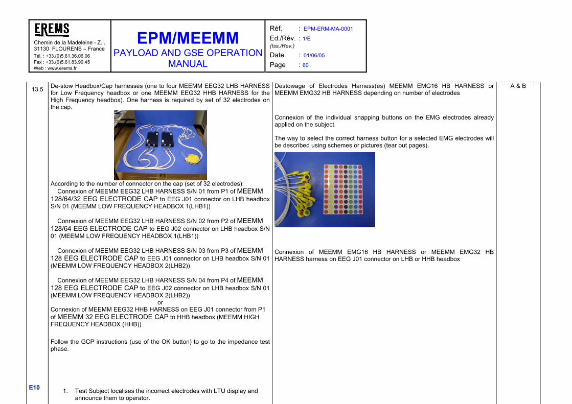
Chemin de la Madeleine - Z.I.31130 FLOURENS – France Tél. : +33.(0)5.61.36.06.06 Fax : +33.(0)5.61.83.99.45 Web : www.erems.fr
EPM/MEEMM PAYLOAD AND GSE OPERATION
MANUAL
Réf. : EPM-ERM-MA-0001 Ed./Rév. : 1/E (Iss./Rev.)
Date : 01/06/05 Page : 60
E10
13.5 De-stow Headbox/Cap harnesses (one to four MEEMM EEG32 LHB HARNESS for Low Frequency headbox or one MEEMM EEG32 HHB HARNESS for the High Frequency headbox). One harness is required by set of 32 electrodes on the cap.
According to the number of connector on the cap (set of 32 electrodes):
Connexion of MEEMM EEG32 LHB HARNESS S/N 01 from P1 of MEEMM 128/64/32 EEG ELECTRODE CAP to EEG J01 connector on LHB headbox S/N 01 (MEEMM LOW FREQUENCY HEADBOX 1(LHB1))
Connexion of MEEMM EEG32 LHB HARNESS S/N 02 from P2 of MEEMM 128/64 EEG ELECTRODE CAP to EEG J02 connector on LHB headbox S/N 01 (MEEMM LOW FREQUENCY HEADBOX 1(LHB1))
Connexion of MEEMM EEG32 LHB HARNESS S/N 03 from P3 of MEEMM 128 EEG ELECTRODE CAP to EEG J01 connector on LHB headbox S/N 01 (MEEMM LOW FREQUENCY HEADBOX 2(LHB2))
Connexion of MEEMM EEG32 LHB HARNESS S/N 04 from P4 of MEEMM 128 EEG ELECTRODE CAP to EEG J02 connector on LHB headbox S/N 01 (MEEMM LOW FREQUENCY HEADBOX 2(LHB2))
or Connexion of MEEMM EEG32 HHB HARNESS on EEG J01 connector from P1 of MEEMM 32 EEG ELECTRODE CAP to HHB headbox (MEEMM HIGH FREQUENCY HEADBOX (HHB))
Follow the GCP instructions (use of the OK button) to go to the impedance test phase.
1. Test Subject localises the incorrect electrodes with LTU display and announce them to operator.
Destowage of Electrodes Harness(es) MEEMM EMG16 HB HARNESS or MEEMM EMG32 HB HARNESS depending on number of electrodes
Connexion of the individual snapping buttons on the EMG electrodes already applied on the subject.
The way to select the correct harness button for a selected EMG electrodes will be described using schemes or pictures (tear out pages).
Connexion of MEEMM EMG16 HB HARNESS or MEEMM EMG32 HB HARNESS harness on EEG J01 connector on LHB or HHB headbox
A & B
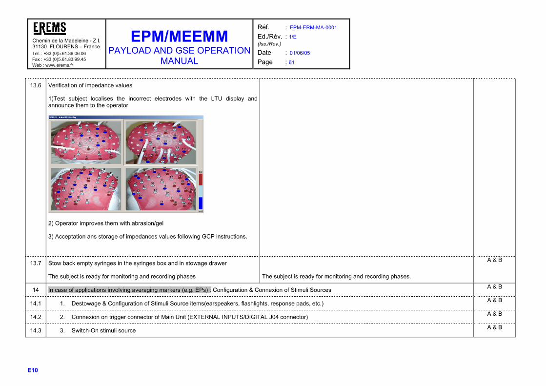
Chemin de la Madeleine - Z.I.31130 FLOURENS – France Tél. : +33.(0)5.61.36.06.06 Fax : +33.(0)5.61.83.99.45 Web : www.erems.fr
EPM/MEEMM PAYLOAD AND GSE OPERATION
MANUAL
Réf. : EPM-ERM-MA-0001 Ed./Rév. : 1/E (Iss./Rev.)
Date : 01/06/05 Page : 61
E10
13.6 Verification of impedance values
1)Test subject localises the incorrect electrodes with the LTU display and announce them to the operator
2) Operator improves them with abrasion/gel
3) Acceptation ans storage of impedances values following GCP instructions.
13.7 Stow back empty syringes in the syringes box and in stowage drawer
The subject is ready for monitoring and recording phases
The subject is ready for monitoring and recording phases.
A & B
14 In case of applications involving averaging markers (e.g. EPs) : Configuration & Connexion of Stimuli Sources A & B
14.1 1. Destowage & Configuration of Stimuli Source items(earspeakers, flashlights, response pads, etc.) A & B
14.2 2. Connexion on trigger connector of Main Unit (EXTERNAL INPUTS/DIGITAL J04 connector) A & B
14.3 3. Switch-On stimuli source A & B
Chemin de la Madeleine - Z.I.31130 FLOURENS – France Tél. : +33.(0)5.61.36.06.06 Fax : +33.(0)5.61.83.99.45 Web : www.erems.fr
EPM/MEEMM PAYLOAD AND GSE OPERATION
MANUAL
Réf. : EPM-ERM-MA-0001 Ed./Rév. : 1/E (Iss./Rev.)
Date : 01/06/05 Page : 62
E10
15 Operator takes back LTU A & B
16 Quick monitoring display before acquisition (refer to paragraph 4.3.1), following the GCP instructions. Use the OK button to go from one step to the next one. A & B
16.1 1. Display screens of EEG/EMG data (screens defined in the selected profile):
o Quick look at EEG/EMG signal
o Display screens of FFT data (screens defined in the selected profile)
A & B
16.2 2. In case of applications involving averaging markers (e.g. EPs) : verification of the stimuli acquisition A & B

Chemin de la Madeleine - Z.I.31130 FLOURENS – France Tél. : +33.(0)5.61.36.06.06 Fax : +33.(0)5.61.83.99.45 Web : www.erems.fr
EPM/MEEMM PAYLOAD AND GSE OPERATION
MANUAL
Réf. : EPM-ERM-MA-0001 Ed./Rév. : 1/E (Iss./Rev.)
Date : 01/06/05 Page : 63
E10
RECORDING STEPS PHOTOGRAMMETRY
A
B partially
17 The operator accepts the start of the recording (+ start of stimuli execution (in case of applications involving averaging markers (e.g. EPs))), following the GCP instructions. Use the OK button to go from one step to the next one.
A & B
18 Data recording, display by operator of the monitoring data (EEG, EP, EMG, FFT), following the GCP instructions. Use the OK button to go from one step to the next one.
The operator checks correct session behaviour (criteria to be detailed by scientist and provided in on board procedures)
The way to synchronise MEEMM recording and the stimulator in the operational point of view has to be discussed.
A
B partially depending on stimuli
type
19 Automatic stop of the recording and the acquisition after a defined period or at the end of of stimulation (in case of applications involving averaging markers (e.g. EPs))
A & B
20 Optional Impedance check at the end of the session A & B
In case of EEG application : In case of EMG application :
20.1 Operator accept impedance mode on LTU MMI and store the final impedances values following the GCP instructions.
- A & B
21 In case of use of digitising tools : Electrode location picturing A & B
21.1 1. Destowage of camera (MEEMM CAMERA), camera harness (MEEMM CAMERA HARNESS) & compact flash (MEEMM COMPACT FLASHDISK) and adaptor (MEEMM COMPACT FLASH ADAPTER), scale ruler (MEEMM SCALE RULER)
2. Camera is packed inside transparent bag and has to be examined for glass splinters (lens, flash, display and view finder) by the crew before the first unpacking after launch
A & B
Chemin de la Madeleine - Z.I.31130 FLOURENS – France Tél. : +33.(0)5.61.36.06.06 Fax : +33.(0)5.61.83.99.45 Web : www.erems.fr
EPM/MEEMM PAYLOAD AND GSE OPERATION
MANUAL
Réf. : EPM-ERM-MA-0001 Ed./Rév. : 1/E (Iss./Rev.)
Date : 01/06/05 Page : 64
E10
21.2 3. Insertion of compact flash (MEEMM COMPACT FLASHDISK)
4. Connection of camera Harness (MEEMM CAMERA HARNESS) to main Unit Front Panel (CAMERA POWER J06) and to Camera (MEEMM CAMERA J01) (to be done by the operator to avoid arc discharge at camera level)
5. Switch ON the CAMERA POWER SWITCH on the MEEMM front panel (to be done by the operator to avoid arc discharge at camera level)
6. The operator switches ON the camera
7. Fix the scale ruler on the subject cap using the dedicated velcro.
A & B
21.3 8. Camera configuration and photos
o The steps to configure the camera and to take the photos are described in RD26 “EPM/MEEMM 3D Electrodes Modelling User Manual” o The principle is to take consider the head as a cube (25 photograph to have a complete cover of the head),:
-a : cube tops -b : cube middle-edges
-c : cube middle-face and top
A & B

Chemin de la Madeleine - Z.I.31130 FLOURENS – France Tél. : +33.(0)5.61.36.06.06 Fax : +33.(0)5.61.83.99.45 Web : www.erems.fr
EPM/MEEMM PAYLOAD AND GSE OPERATION
MANUAL
Réf. : EPM-ERM-MA-0001 Ed./Rév. : 1/E (Iss./Rev.)
Date : 01/06/05 Page : 65
E10
21.4 9. Transfer from camera to LTU : o De-insert compact flash disk from camera o Using adaptor, insert in LTU o Transfer Pictures from Flashdisk to LTU o Wait for Acknowledge from LTU for the picture correct transfer o De-insert flashdisk o Stow back flash-disk, adaptor and camera
A & B
Automatic Transfer from the LTU to MEEMM Main Unit o using the LAN interface o storing them in the removable hard disk with the associated session experiment raw data

Chemin de la Madeleine - Z.I.31130 FLOURENS – France Tél. : +33.(0)5.61.36.06.06 Fax : +33.(0)5.61.83.99.45 Web : www.erems.fr
EPM/MEEMM PAYLOAD AND GSE OPERATION
MANUAL
Réf. : EPM-ERM-MA-0001 Ed./Rév. : 1/E (Iss./Rev.)
Date : 01/06/05 Page : 66
E10
PACKING STEPS A, B
22 Desinstallation of test subject A & B
22.1 • Disconnection of EEG or EMG sensors from the headboxes A & B
22.2 • Take away restrainers from test subject and stow back in ISS A & B
23 In case of applications involving averaging markers (e.g. EPs) : Desinstallation of stimuli source items A
23.1 • Switch-off stimuli source A
23.2 • Desinstallation of subject items (ear plugs, flashing goggles or else...) A
23.3 • Disconnection of stimuli/trigger source connector from trigger connector on front Panel A
23.4 • Stow back Stimuli/Trigger items in their affectation A
24 Close MEEMM Application on LTU A
25 Switch –off Main Unit A
26 In case of use of digitising tools : Disconnect camera and its Harness and stow back A
27 Disconnect Headbox(es) and harnesses from the Main Unit A
28 Stow back Headbox(es) and harness(es) in stowage drawer A
29 Deinsert Hard disk and put it with the used-disks in stowage drawer A
30 Sensor set desinstallation & Cleaning
In case of EEG application : In case of EMG application :
A & B
30.1 Take-off EEG/EMG sensors A & B

Chemin de la Madeleine - Z.I.31130 FLOURENS – France Tél. : +33.(0)5.61.36.06.06 Fax : +33.(0)5.61.83.99.45 Web : www.erems.fr
EPM/MEEMM PAYLOAD AND GSE OPERATION
MANUAL
Réf. : EPM-ERM-MA-0001 Ed./Rév. : 1/E (Iss./Rev.)
Date : 01/06/05 Page : 67
E10
30.2 Stow back the cap in the used items to download Throw away in trash collector used EMG electrodes B
30.3 Destow cleaning wipes and Humid Towels if required B
30.4 Clean the Subject Head using Humid Towels & cleaning wipes Clean EMG electrode free locations with cleaning wipes A & B
Throw away in trash collector used cleaning wipes and Humid Towels B

Chemin de la Madeleine - Z.I.31130 FLOURENS – France Tél. : +33.(0)5.61.36.06.06 Fax : +33.(0)5.61.83.99.45 Web : www.erems.fr
EPM/MEEMM PAYLOAD AND GSE OPERATION
MANUAL
Réf. : EPM-ERM-MA-0001 Ed./Rév. : 1/E (Iss./Rev.)
Date : 01/06/05 Page : 68
E10
4.2.2.2 Ambulatory and sleep procedure
Two modes are planned for PORTEEM on-board operations : o Stand alone recording o Stand alone recording and occasional remote monitoring using the EPM laptop for signal quality check before recording. This mode is the most convivial one as its
allows both to check what you are going to record and also to command the start/stop order using dedicated icons without requiring the use of the Vitaport 2 LCD and operating keys.
Step Task Crew concerne
d
PREPARATION AND MONITORING STEPS
Stand alone recording with occasional remote monitoring Stand alone recording A, B
1 Destowage and preparation of the PORTEEM (MEEMM PORTEEM CORE UNIT) including 4 fresh batteries (MEEMM PORTEEM BATTERIES) & compact flash (MEEMM COMPACT FLASHDISK) and adapter (MEEMM COMPACT FLASH ADAPTER)
A or B

Chemin de la Madeleine - Z.I.31130 FLOURENS – France Tél. : +33.(0)5.61.36.06.06 Fax : +33.(0)5.61.83.99.45 Web : www.erems.fr
EPM/MEEMM PAYLOAD AND GSE OPERATION
MANUAL
Réf. : EPM-ERM-MA-0001 Ed./Rév. : 1/E (Iss./Rev.)
Date : 01/06/05 Page : 69
E10
1.1 • Unscrewing the door of the battery compartment and fix it on the velcropatch on the PORTEEM side • Place the batteries in the recorder base after. • Inspect the “+” and “-“ signs to ensure correct placement. • Screw back the battery cover
A or B
1.2 • Insertion of flashdisk in PORTEEM A or B
2 Fix the PORTEEM on the subject A & B
3 Destowage of appropriate sensor harnesses (connection), sensors and accessories (held by test subject) A or B
3.1 Destowage of cleaning wipes A or B
3.2 Destowage of 12-electrode cap (MEEMM 12 EEG ELECTRODE CAP) and 1 syringe box (MEEMM SYRINGES BOX)
Destowage of adhesive roller (MEEMM ADHESIVE ROLLER) and specific gluing cream (MEEMM SIGNA CREAM TUBE) for face individual electrodes
A or B
3.3 Destowage of Strain Gauge (MEEMM PORTEEM STRAIN GAUGE SENSOR+ MEEMM PORTEEM STRAIN GAUGE SENSOR)
Destowage of EMG electrodes packets (MEEMM EMG SINGLE ELECTRODE) or (MEEMM EMG DUAL ELECTRODE)
Destowage EMG (MEEMM PORTEEM EMG WIRE S/N 01 to 04) and ECG wires (MEEMM PORTEEM ECG WIRE S/N 01 to 02)
Destowage of patchpanel (MEEMM PORTEEM PATCHPANEL)
A or B
3.4 Destowage of Optilink (MEEMM PORTEEM OPTILINK) - A or B

Chemin de la Madeleine - Z.I.31130 FLOURENS – France Tél. : +33.(0)5.61.36.06.06 Fax : +33.(0)5.61.83.99.45 Web : www.erems.fr
EPM/MEEMM PAYLOAD AND GSE OPERATION
MANUAL
Réf. : EPM-ERM-MA-0001 Ed./Rév. : 1/E (Iss./Rev.)
Date : 01/06/05 Page : 70
E10
4 Preparation, mounting & functionality insurance of the electrode set. Installation time indication (RD18 “EPM/MEEMM Operational Analysis Report”) will be inserted in the procedures to guide the operator.
For all steps of this task, photos will be added showing the positioning of the subject, the operator and the equipment and inserted as tear out pages in the on board user manual. These tear out pages will contain legend notes reminding the good tips related to the task.
Refer to steps 13.1, 13.2, 13.3 and 13.4 of the stationary steps.
A & B
4.5 Connect the EEG cap (MEEMM 12 EEG ELECTRODE CAP) to the patchpanel (MEEMM PORTEEM PATCHPANEL) following the end labels on the cap plugs.
A & B
4.6 Stow back empty syringes in the syringes box and in stowage drawer A & B
4.7 Installation of EMG and ECG electrodes 1. For each individual electrode, the operator has to clean the skin for the electrodes and fix the electrodes (one by one or one pair by one pair according to
the type of electrodes). 2. Connexion of the individual snapping buttons on the EMG & ECG electrodes already applied on the subject. The way to select the correct location a
selected EMG/ECG electrodes will be described using schemes or pictures (tear out pages). 3. Connect the EMG (MEEMM PORTEEM EMG WIRE S/N 01 to 04) and the ECG wires (MEEMM PORTEEM ECG WIRE S/N 01 to 02) to the patchpanel
following the end labels on the electrodes plugs..
A & B

Chemin de la Madeleine - Z.I.31130 FLOURENS – France Tél. : +33.(0)5.61.36.06.06 Fax : +33.(0)5.61.83.99.45 Web : www.erems.fr
EPM/MEEMM PAYLOAD AND GSE OPERATION
MANUAL
Réf. : EPM-ERM-MA-0001 Ed./Rév. : 1/E (Iss./Rev.)
Date : 01/06/05 Page : 71
E10
4.8 Install the strain gauge sensor (MEEMM PORTEEM STRAIN GAUGE SENSOR)around the subject chest
Connect the strain gauge sensor ((MEEMM PORTEEM STRAIN GAUGE SENSOR) to the patchpanel (MEEMM PORTEEM PATCHPANEL) with the dedicated adaptor (MEEMM PORTEEM STRAIN GAUGE ADAPTOR) The way to Install the strain gauge sensor around the subject chest will be described using schemes or pictures (tear out pages).
A & B
5 Connect the Vitaport via the Optilink (MEEMM PORTEEM OPTILINK) to the laptop
- B
6 Start the Columbus program - B
7 The subject power ON the recorder (not to be performed by the operator to avoid arc discharge)
Press OK key to install VPDOS if asked on PORTEEM LCD
B
8 Select the correct Definition (or Montage) file using the PORTEEM SW.
Note : the use of the the PORTEEM SW in the EPM environment is not defined yet.
Select the correct Definition (or Montage) file thanks to the recorder sub-menus displayed on the LCD, using the operating keys. B
9 Install the subject A & B
10 Start the acquisition A & B
10.1 Click the “Connect recorder” button to allow exchanges between the recorder equipment and the Columbus SW
- A & B

Chemin de la Madeleine - Z.I.31130 FLOURENS – France Tél. : +33.(0)5.61.36.06.06 Fax : +33.(0)5.61.83.99.45 Web : www.erems.fr
EPM/MEEMM PAYLOAD AND GSE OPERATION
MANUAL
Réf. : EPM-ERM-MA-0001 Ed./Rév. : 1/E (Iss./Rev.)
Date : 01/06/05 Page : 72
E10
10.2 Perform visual control to check the quality and the sensitivity of the incoming signals before starting the actual recording. Using the Columbus IF (View on-line menu & Start view amplifier)
- A & B
10.3 Start the recording by laptop via clicking the “Remote control” button and associated sub-menus
Start the recording by hand by simply pushing the OK key when the LCD displays “Start recording ?” A & B
10.4 Click the “Disconnect recorder” button to end the exchange between the recorder equipment and the Columbus SW
- A & B
10.5 Disconnect the Vitaport from the Optilink and the laptop - A & B
Chemin de la Madeleine - Z.I.31130 FLOURENS – France Tél. : +33.(0)5.61.36.06.06 Fax : +33.(0)5.61.83.99.45 Web : www.erems.fr
EPM/MEEMM PAYLOAD AND GSE OPERATION
MANUAL
Réf. : EPM-ERM-MA-0001 Ed./Rév. : 1/E (Iss./Rev.)
Date : 01/06/05 Page : 73
E10
RECORDING STEPS
Stand alone recording with occasional remote monitoring Stand alone recording
A
B (if on line monitoring)
11 Various functions can be monitored via the LCD (batteries, recording time…)
With laptop re-connection, visual controls using the Optilink and the laptop can also be performed during the recording using the Columbus SW, without affecting the recording session.
Various functions can be monitored via the LCD (batteries, recording time…) A & B
12 Stop the recording by hand by simply pushing the OK key when the LCD displays “Stop recording ?”
With laptop re-connection, stop the recording by laptop via clicking the “Remote control” button and associated sub-menus
Stop the recording by hand by simply pushing the OK key when the LCD displays “Stop recording ?”
A
13 Disconnect the Vitaport from the Optilink and the laptop - A
14 Power OFF the recorder A
15 Close the PORTEEM SW on the LTU - A

Chemin de la Madeleine - Z.I.31130 FLOURENS – France Tél. : +33.(0)5.61.36.06.06 Fax : +33.(0)5.61.83.99.45 Web : www.erems.fr
EPM/MEEMM PAYLOAD AND GSE OPERATION
MANUAL
Réf. : EPM-ERM-MA-0001 Ed./Rév. : 1/E (Iss./Rev.)
Date : 01/06/05 Page : 74
E10
PACKING STEPS
Stand alone recording with occasional remote monitoring Stand alone recording A
16 Deconnection of cap connector A
16 Data archiving
De-insert flashdisk from PORTEEM
A
17 Optional steps : Insert flashdisk in LTU and transfer data to the SMSC (To be completed) A
18 Disconnect PORTEEM and harnesses A
19 Stow back PORTEEM and harnesses in stowage drawer A
20 Sensor set desinstallation & Cleaning A
20.1 • Cap take-off A
20.2 • Cap stowing back in the used items to download A
20.3 • Subject Head cleaning (use of Humid Towels) A

Chemin de la Madeleine - Z.I. 31130 FLOURENS – France Tél. : +33.(0)5.61.36.06.06 Fax : +33.(0)5.61.83.99.45 Web : www.erems.fr
EPM/MEEMM PAYLOAD AND GSE OPERATION
MANUAL
Réf. : EPM-ERM-MA-0001 Ed./Rév. : 1/E (Iss./Rev.)
Date : 01/06/05 Page : 75
E10
4.3 EXAMPLE OF COMPLETE SCENARIO ASSOCIATED DISPLAY This paragraph provides various types of the MMI displays. MMI technical details are described in RD2 document (MEEMM SW User Manual).
4.3.1 STATIONARY EQUIPMENT Here are the crew displays proposed by EREMS and INSERM Lyon for a classical P300 experiment protocol with 128 electrodes : 1) Impedance screen : One screen with 4 views (sides, back and top) of the 128 electrode EEG cap placed on a subject head (photos taken on ground and inserted within the session profile). The screen is splitted within 4 parts. The electrodes are numbered both on the cap and on the screen.
Figure 21 : Typical Impedance screen display (32 EEG cap)
Press OK button to accept the impedance values (impedance values storage with the session raw EEG data files) 2) EEG scrolling screens : Scrolling of 8 EEG screens, each screen displaying 16 raw EEG curves. A fixed timer is used to go to one screen to the other within astronaut action. The EEG display scales will be defined within the session profile taking into account astronaut EEG ground sessions.

Chemin de la Madeleine - Z.I. 31130 FLOURENS – France Tél. : +33.(0)5.61.36.06.06 Fax : +33.(0)5.61.83.99.45 Web : www.erems.fr
EPM/MEEMM PAYLOAD AND GSE OPERATION
MANUAL
Réf. : EPM-ERM-MA-0001 Ed./Rév. : 1/E (Iss./Rev.)
Date : 01/06/05 Page : 76
E10
Figure 22 : Typical EEG scrolling screen display
Press OK button, once all the screens are corrects. The astronaut can be helped by paper support with his proper EEG typical responses, recording on ground during training sessions. 3) FFT screen : One FFT screen displaying 4 to 8 FFT curves. The selection of FFT curves and display scales will be done within the session profile.
Figure 23 : Typical FFT screen display
Press OK button, once all the FFT are corrects. The astronaut can be helped by paper support with expected FFT responses.

Chemin de la Madeleine - Z.I. 31130 FLOURENS – France Tél. : +33.(0)5.61.36.06.06 Fax : +33.(0)5.61.83.99.45 Web : www.erems.fr
EPM/MEEMM PAYLOAD AND GSE OPERATION
MANUAL
Réf. : EPM-ERM-MA-0001 Ed./Rév. : 1/E (Iss./Rev.)
Date : 01/06/05 Page : 77
E10
4) Session monitoring screen : One screen is required, splitted vertically in 2 parts. Fist part : One EEG screen (10 s duration) with up to 16 raw EEG curves. The EEG display scales will be defined within the session profile taking into account astronaut EEG ground sessions. Second part : 2 EP zones (1 EP zone = 1 trigger class) with one or more electrodes (EPs parameters selected within the session profile).
Figure 24 : Typical session monitoring screen display
Press OK button, once all the acquisition are correct (stimulator, stressors OK, EEG), to begin the recording (EP reset). The operations linked to the stimulator have to be defined as it impacts on the MEEMM start/stop recording protocol and raw data sub files management.
Chemin de la Madeleine - Z.I. 31130 FLOURENS – France Tél. : +33.(0)5.61.36.06.06 Fax : +33.(0)5.61.83.99.45 Web : www.erems.fr
EPM/MEEMM PAYLOAD AND GSE OPERATION
MANUAL
Réf. : EPM-ERM-MA-0001 Ed./Rév. : 1/E (Iss./Rev.)
Date : 01/06/05 Page : 78
E10
4.3.2 AMBULATORY AND SLEEP EQUIPMENT The PORTEEM equipment is a standalone equipment. Occasional monitoring are possible in case of temporary PORTEEM connection with the LTU using the Optilink harness.
In case of monitoring using PORTEEM SW (refer to RD23 “Columbus User’s manual”), no screen sequence are used, only one on line screen can be displayed.
Figure 25 : Typical signals for PORTEEM sleep session
Chemin de la Madeleine - Z.I. 31130 FLOURENS – France Tél. : +33.(0)5.61.36.06.06 Fax : +33.(0)5.61.83.99.45 Web : www.erems.fr
EPM/MEEMM PAYLOAD AND GSE OPERATION
MANUAL
Réf. : EPM-ERM-MA-0001 Ed./Rév. : 1/E (Iss./Rev.)
Date : 01/06/05 Page : 79
E10
5 MAINTENANCE PLAN AND INSTRUCTIONS This section will be completed at a later stage to cover the following information (synthesis of AD7 “EPM/MEEMM Maintainability Assessment and Inputs to Maintenance Plan”) :
• Plan and instructions for preventive maintenance • Instruction for corrective maintenance • Required tools and skills for maintenance
At the moment, these information are provided within AD7 “EPM/MEEMM Maintainability Assessment and Inputs to Maintenance Plan”. Two main connectors are available for maintenance and trouble shooting :
- Test Link (J05) - SW Download (J08)
Refer to paragraph 7 for connector pin out. The SW procedures linked to trouble shooting operations are described in the dedicated “SW user Manual” (refer to RD2).

Chemin de la Madeleine - Z.I. 31130 FLOURENS – France Tél. : +33.(0)5.61.36.06.06 Fax : +33.(0)5.61.83.99.45 Web : www.erems.fr
EPM/MEEMM PAYLOAD AND GSE OPERATION
MANUAL
Réf. : EPM-ERM-MA-0001 Ed./Rév. : 1/E (Iss./Rev.)
Date : 01/06/05 Page : 80
E10
6 SPECIAL TOOLS The list of standard tools needed for the MEEMM operation, installation or maintenance is the following : It has to be noted that some of these tools will not be used in the baseline option for MEEMM headboxes fixation on the rack (use of velcro instead of Seat track).
Tool Name Document-chapter where tool is
described
Tools required for
Routing cleaning/disinfection
AD5 Section 8 Cleaning of skin of the test subject and of his head after experiment sessions
Trash collection and trash compaction
AD5 Section 8 Collection of the used consumables after experiment
Personal restraints AD5 Section 8 Restraint of the test subject during experiment sessions and restraint of the operator nearby the test subject when fitting the cap and electrodes on the test subject
Tool kit P-Consumables Duct tape
AD5 Section 8 Fixing of the cap harness on the shoulder of the subject during experiment
Tool kit P-Consumables wet and dry wipes
AD5 Section 8 Cleaning of skin of the test subject and of his head after experiment sessions
Tool kit P-Consumables Velcro
AD5 Section 8 Fixing of deployable items
Articulating Post Assembly (AP) Part nbr G11F5122-1
RD14 chapter 1.2 « Equipment Restraints »
Fixing of Headboxes to Seat Track (AP fixed on Seat Track)
Seat track Equpment Anchor Assembly (STEA) Part nbr G11F5120-1
RD14 chapter 1.2 « Equipment Restraints »
Fixing of Headboxes to Seat Track (STEA fixed on AP)
Adjustable Length Tether Assembly (ALT)) Part nbr G11F5140-1
RD14 chapter 1.2 « Equipment Restraints »
Fixing of Headboxes to Seat Track (ALT fixed on STEA, ALT straps the Headbox (es))
Table 9 : COLUMBUS / ISS standard tools used by MEEMM
The list of MEEMM specific tools or equipment needed for the installation, deinstallation, operation or maintenance is the following :
Tool Name Operation the tool is required for Reason why no COLUMBUS standard tool could be used
Compact flash disk adapter
OPERATION used for camera mini flash disk to adapt it to standard flash disk size
MEEMM specific
Calibration plug
MAINTENANCE (preventive) used for calibrating MEEMM amplifiers
Adapted to MEEMM specific connector
Downloading plug
MAINTENANCE (preventive/corrective) used to allow downloading of Supervisor SW by crew or by ground
Adapted to MEEMM specific connector
Table 10 : Tools provided by MEEMM
Note : The MEEMM SM requires an external stimulator for most of the experiments (Evoked Potentials).

Chemin de la Madeleine - Z.I. 31130 FLOURENS – France Tél. : +33.(0)5.61.36.06.06 Fax : +33.(0)5.61.83.99.45 Web : www.erems.fr
EPM/MEEMM PAYLOAD AND GSE OPERATION
MANUAL
Réf. : EPM-ERM-MA-0001 Ed./Rév. : 1/E (Iss./Rev.)
Date : 01/06/05 Page : 81
E10
The environment conditions are very important when making Evoked Potential measurements; as their objective is to study the reaction of the brain to specific stimuli (for example visual) the subject should be in a calm environment (avoiding for example flashing leds or sounds which would completely change the responses of the brain).
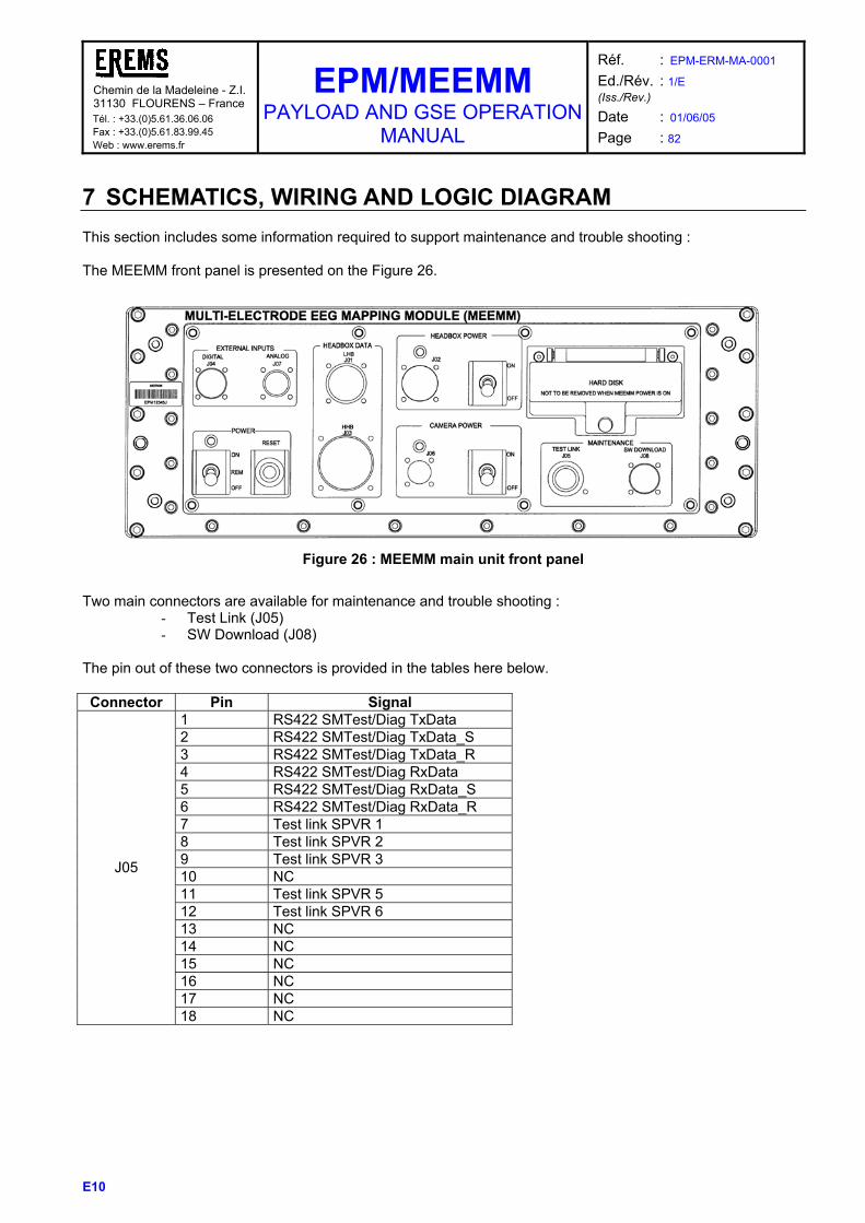
Chemin de la Madeleine - Z.I. 31130 FLOURENS – France Tél. : +33.(0)5.61.36.06.06 Fax : +33.(0)5.61.83.99.45 Web : www.erems.fr
EPM/MEEMM PAYLOAD AND GSE OPERATION
MANUAL
Réf. : EPM-ERM-MA-0001 Ed./Rév. : 1/E (Iss./Rev.)
Date : 01/06/05 Page : 82
E10
7 SCHEMATICS, WIRING AND LOGIC DIAGRAM This section includes some information required to support maintenance and trouble shooting : The MEEMM front panel is presented on the Figure 26.
Figure 26 : MEEMM main unit front panel
Two main connectors are available for maintenance and trouble shooting :
- Test Link (J05) - SW Download (J08)
The pin out of these two connectors is provided in the tables here below. Connector Pin Signal
1 RS422 SMTest/Diag TxData 2 RS422 SMTest/Diag TxData_S 3 RS422 SMTest/Diag TxData_R 4 RS422 SMTest/Diag RxData 5 RS422 SMTest/Diag RxData_S 6 RS422 SMTest/Diag RxData_R 7 Test link SPVR 1 8 Test link SPVR 2 9 Test link SPVR 3 10 NC 11 Test link SPVR 5 12 Test link SPVR 6 13 NC 14 NC 15 NC 16 NC 17 NC
J05
18 NC

Chemin de la Madeleine - Z.I. 31130 FLOURENS – France Tél. : +33.(0)5.61.36.06.06 Fax : +33.(0)5.61.83.99.45 Web : www.erems.fr
EPM/MEEMM PAYLOAD AND GSE OPERATION
MANUAL
Réf. : EPM-ERM-MA-0001 Ed./Rév. : 1/E (Iss./Rev.)
Date : 01/06/05 Page : 83
E10
Connector Pin Signal
1 Structure GND 2 GND 3 CPU_board_J11 GREEN 4 CPU_board_J11 RED 5 CPU_board_J11 GND 6 CPU_board_J11 SCLK 7 GND 8 Select Main/Red 9 CPU_board_J16 KBCLK 10 CPU_board_J16 VCC 11 SPVR Telech_R 12 SPVR Telech 13 CPU_board_J15 VCC 14 CPU_board_J15 MDATA 15 CPU_board_J15 MCLK 16 CPU_board_J11 BLUE 17 CPU_board_J11 SDATA 18 CPU_board_J11 VSYNC 19 CPU_board_J16 GND 20 CPU_board_J16 KBDATA 21 CPU_board_J15 GND
J08
22 CPU_board_J11 HSYNC • All the maintenance tasks are described in AD7 “EPM/MEEMM Maintainability Assessment and Inputs to Maintenance
Plan”.

Chemin de la Madeleine - Z.I. 31130 FLOURENS – France Tél. : +33.(0)5.61.36.06.06 Fax : +33.(0)5.61.83.99.45 Web : www.erems.fr
EPM/MEEMM PAYLOAD AND GSE OPERATION
MANUAL
Réf. : EPM-ERM-MA-0001 Ed./Rév. : 1/E (Iss./Rev.)
Date : 01/06/05 Page : 84
E10
8 TRANSPORTATION, PACKAGING, HANDLING AND STORAGE For transportation and storage , the MEEMM containers comply with the requirements specified in AD3 “Science Module Interface Requirements Document (SMIRD) for the European Physiology Module”. It has to be noted that the MEEMM containers includes some limited life items (refer to RD24 “Delivery Item List”). These items have to be stored in classical environment (ambient temperature, 50% humidity). The delivered material has been cleaned at EREMS, standard FM cleaning rules have to be applied at the integration sites. The list of delivered MEEMM items and the content of each containers (4 mains containers) are provided in the shipment list of the ADP. All the items are separately enclosed in antistatic pockets. The following photos present the container organisation. Container 1 : MEEMM Main Unit Container 2 : Headboxes, HD, harnesses
Container 3 : Caps and consumables
Container 4 : GSE items.

Chemin de la Madeleine - Z.I. 31130 FLOURENS – France Tél. : +33.(0)5.61.36.06.06 Fax : +33.(0)5.61.83.99.45 Web : www.erems.fr
EPM/MEEMM PAYLOAD AND GSE OPERATION
MANUAL
Réf. : EPM-ERM-MA-0001 Ed./Rév. : 1/E (Iss./Rev.)
Date : 01/06/05 Page : 85
E10
9 INSTALLATION PROCEDURE This paragraph describes the installation steps of the MEEMM and its GSE environment in standalone configuration.
9.1 MEEMM/GSE SET-UP The general GSE configuration is depicted in the following figure. This configuration includes the MEEMM Main Unit and the GSE.
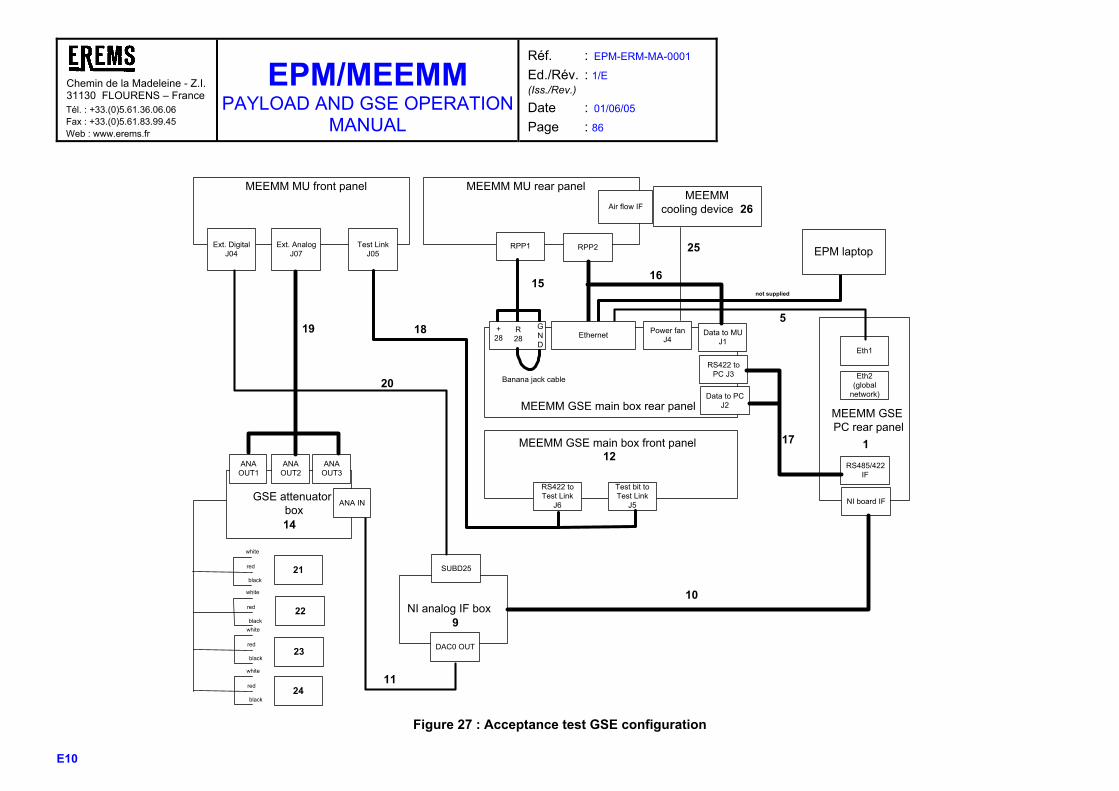
Chemin de la Madeleine - Z.I.31130 FLOURENS – France Tél. : +33.(0)5.61.36.06.06 Fax : +33.(0)5.61.83.99.45 Web : www.erems.fr
EPM/MEEMM PAYLOAD AND GSE OPERATION
MANUAL
Réf. : EPM-ERM-MA-0001 Ed./Rév. : 1/E (Iss./Rev.)
Date : 01/06/05 Page : 86
E10
MEEMM MU front panel MEEMM MU rear panel
Air flow IFMEEMM
cooling device 26
MEEMM GSE main box rear panel
MEEMM GSE main box front panel
MEEMM GSE PC rear panel
GSE attenuator box
NI analog IF box
SUBD25
DAC0 OUT
Ext. DigitalJ04
Ext. AnalogJ07
Test LinkJ05
ANAOUT1
ANAOUT2
ANAOUT3
20
19
9
14
white
red
black
white
red
black
white
red
black
white
red
black21
22
23
24
NI board IFANA IN
11
10
1
RS485/422IF
Data to MUJ1
RS422 toPC J3
RPP2RPP1
16
17
Eth2(global
network)
Eth1
EPM laptop
not supplied
5Ethernet Power fan
J4
25
15
RS422 toTest Link
J6
18
12
Data to PCJ2
Test bit toTest Link
J5
+28
R28
GND
Banana jack cable
Figure 27 : Acceptance test GSE configuration
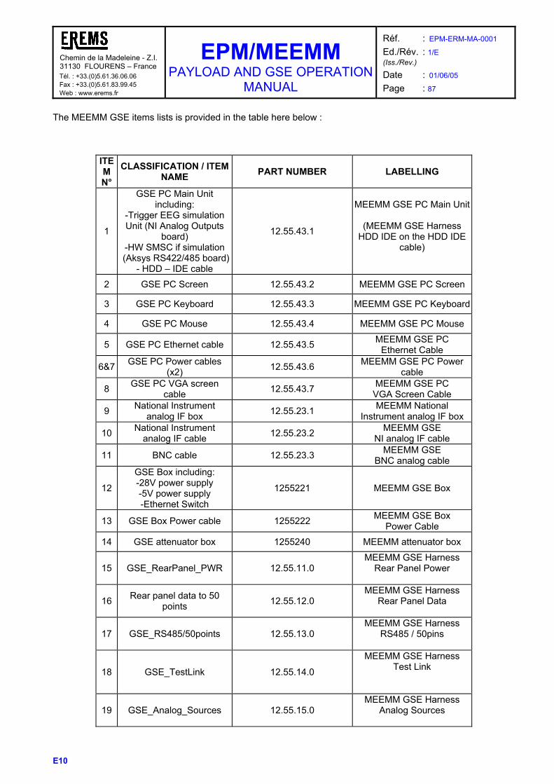
Chemin de la Madeleine - Z.I. 31130 FLOURENS – France Tél. : +33.(0)5.61.36.06.06 Fax : +33.(0)5.61.83.99.45 Web : www.erems.fr
EPM/MEEMM PAYLOAD AND GSE OPERATION
MANUAL
Réf. : EPM-ERM-MA-0001 Ed./Rév. : 1/E (Iss./Rev.)
Date : 01/06/05 Page : 87
E10
The MEEMM GSE items lists is provided in the table here below :
ITEM N°
CLASSIFICATION / ITEM NAME PART NUMBER LABELLING
1
GSE PC Main Unit including:
-Trigger EEG simulation Unit (NI Analog Outputs
board) -HW SMSC if simulation
(Aksys RS422/485 board)- HDD – IDE cable
12.55.43.1
MEEMM GSE PC Main Unit
(MEEMM GSE Harness HDD IDE on the HDD IDE
cable)
2 GSE PC Screen 12.55.43.2 MEEMM GSE PC Screen
3 GSE PC Keyboard 12.55.43.3 MEEMM GSE PC Keyboard
4 GSE PC Mouse 12.55.43.4 MEEMM GSE PC Mouse
5 GSE PC Ethernet cable 12.55.43.5 MEEMM GSE PC Ethernet Cable
6&7 GSE PC Power cables (x2) 12.55.43.6 MEEMM GSE PC Power
cable
8 GSE PC VGA screen cable 12.55.43.7 MEEMM GSE PC
VGA Screen Cable
9 National Instrument analog IF box 12.55.23.1 MEEMM National
Instrument analog IF box
10 National Instrument analog IF cable 12.55.23.2 MEEMM GSE
NI analog IF cable
11 BNC cable 12.55.23.3 MEEMM GSE BNC analog cable
12
GSE Box including: -28V power supply -5V power supply -Ethernet Switch
1255221 MEEMM GSE Box
13 GSE Box Power cable 1255222 MEEMM GSE Box Power Cable
14 GSE attenuator box 1255240 MEEMM attenuator box
15 GSE_RearPanel_PWR 12.55.11.0 MEEMM GSE Harness
Rear Panel Power
16 Rear panel data to 50 points 12.55.12.0
MEEMM GSE Harness Rear Panel Data
17 GSE_RS485/50points 12.55.13.0 MEEMM GSE Harness
RS485 / 50pins
18 GSE_TestLink 12.55.14.0
MEEMM GSE Harness Test Link
19 GSE_Analog_Sources 12.55.15.0 MEEMM GSE Harness
Analog Sources
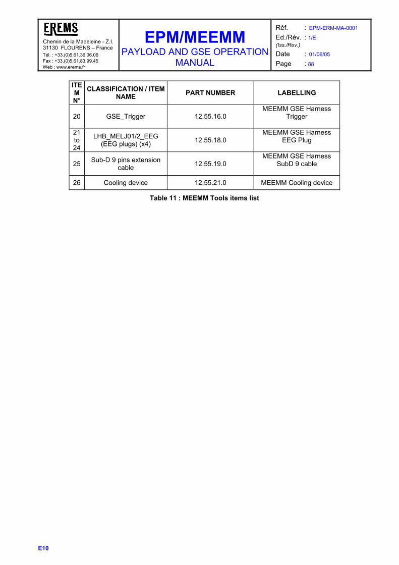
Chemin de la Madeleine - Z.I. 31130 FLOURENS – France Tél. : +33.(0)5.61.36.06.06 Fax : +33.(0)5.61.83.99.45 Web : www.erems.fr
EPM/MEEMM PAYLOAD AND GSE OPERATION
MANUAL
Réf. : EPM-ERM-MA-0001 Ed./Rév. : 1/E (Iss./Rev.)
Date : 01/06/05 Page : 88
E10
ITEM N°
CLASSIFICATION / ITEM NAME PART NUMBER LABELLING
20 GSE_Trigger 12.55.16.0 MEEMM GSE Harness
Trigger
21 to 24
LHB_MELJ01/2_EEG (EEG plugs) (x4) 12.55.18.0
MEEMM GSE Harness EEG Plug
25 Sub-D 9 pins extension cable 12.55.19.0
MEEMM GSE Harness SubD 9 cable
26 Cooling device 12.55.21.0 MEEMM Cooling device
Table 11 : MEEMM Tools items list
Chemin de la Madeleine - Z.I. 31130 FLOURENS – France Tél. : +33.(0)5.61.36.06.06 Fax : +33.(0)5.61.83.99.45 Web : www.erems.fr
EPM/MEEMM PAYLOAD AND GSE OPERATION
MANUAL
Réf. : EPM-ERM-MA-0001 Ed./Rév. : 1/E (Iss./Rev.)
Date : 01/06/05 Page : 89
E10
9.2 INSTALLATION STEPS No specific order is required in the steps to install the GSE complete set-up referred in Figure 27. De-stow all the required items (referred in Table 11) and connect them as describe on the scheme, with the help of the labelling on the harnesses ends. Refer to RD29 “EPM/MEEMM Acceptance test procedures” for examples of standalone procedures.
9.3 GROUND INSTRUCTIONS OF USE The Payload and GSE Operation Manual is the main document providing detailed documentation, data and instructions for operations and maintenance of the payload and ground segment equipment (GSE). This document refers to 3 others User Manual dedicated to SW and Digitizing tasks for some specific operations:
- RD2 :EPM/MEEMM SW User Manual This document describes the use of MEEMM SW The intended readership of this document is : • OHB personal be able to operate the MEEMM during test and integration • Profile developer, i.e. people in charge of developing a scientific session using MEEMM. • Test engineers, as the content of this document shall be known for writing test scripts.
- RD25 : EPM/MEEMM SW Transfer Document
This document identifies the MEEMM Softwares and how to build and install it in the operational environment. The document is updated after main SW releases.
- RD26 : EPM/MEEMM 3D Electrodes Modelling User Manual
This document is in charge to explain the way to proceed to obtain the electrodes location thanks to the Photomodeler software.
Additionally, a synthesis of data and requirements to support the MEEMM/EPM ground integration phase is provided in “Ground Processing data” (RD10). Following the assessments performed in RD30 (CE declaration of conformity), the following usage recommendations or restrictions have to be made. They are mentioned in the CE certificate which is given in Appendix of RD30 :
- MEEMM class is 2A - The CE directive applied is the ANNEX VIII of 93/42/CEE:
MEEMM is a custom-made device: MEEMM device was specifically made in accordance with the European Space Agency (ESA) written requirements with specific design characteristics. GM1, GM2 and BDCM are intended for the sole use of particular Centers in relation with the European Space Agency (ESA) linked with the operation (preparation/exploitation) of the Flight Model onboard the International Space Station. It shall not be used for clinical investigations.
- It complies with the essential relevant requirements of ANNEX I of 93/42/CEE and of IEC 601, with the following exceptions and with restrictions of usage:
o Taking into account the very specific usage, the MEEMM Operation Manual (operating
instructions) is based on a template for the space flight model and differs from the indications shown in the Directive

Chemin de la Madeleine - Z.I. 31130 FLOURENS – France Tél. : +33.(0)5.61.36.06.06 Fax : +33.(0)5.61.83.99.45 Web : www.erems.fr
EPM/MEEMM PAYLOAD AND GSE OPERATION
MANUAL
Réf. : EPM-ERM-MA-0001 Ed./Rév. : 1/E (Iss./Rev.)
Date : 01/06/05 Page : 90
E10
o Regarding the labelling, taking into account the Space Flight requirements and the similarity contraint on the Ground models, the labelling and markings are also in discrepancy with the Directive
o Discrepancies exist with all sections of IEC 60601 taking into account the Usage specificities. In
particular, the main discrepancies (but not exhaustive) are
o The normal condition for the test subject is to be electrically floating, not linked to the ground
o Regarding the Section 3 Article 19 « leakage currents… », the “NASA Medical Safety
Standard”, App. Y: “IRB guidelines regarding In-Flight Electrical Standards associated with bioinstrumentation to be used for in-flight investigative monitoring of shuttle crewmembers” (JSC20483 App. Y) was applied. The values indicated in the IEC 601-1 are covered when MEEMM is used alone. Still , and even when MEEMM is used in combination with other medical systems, the test subject shall be electrically floating, not linked to the ground. Moreover in case of combination with other medical subsystem, depending on their characteristics, the user will have to take care of the possible risk with the addition of leakage currents
o Another EMC standard than the EC directive one (cf section 5 of IEC 601) was applied on
MEEMM. This standard is specified in document EPM-OHB-RQ-006 1/C (corresponding to the International Space Station EMC Environment). MEEMM was tested according to this Standard for Conducted Emission, Conducted Susceptibility, Radiated Emission, Radiated Susceptibilty, ESD Tests. The results are shown in the report EPM-ERM-TRP- 0004, 03/03/03.
o Regarding electrical installation
For GM1 and GM2, MEEMM shall be used only with the Main Unit integrated and powered in the EPM rack The BDCM shall be used only with the Main Unit powered by the MEEMM GSE.
o No defibrilator shall be used when using MEEMM
o Care shall be taken by the user on the position of the electrodes on the test subject, so that no
stimulation can go through the Thorax

Chemin de la Madeleine - Z.I. 31130 FLOURENS – France Tél. : +33.(0)5.61.36.06.06 Fax : +33.(0)5.61.83.99.45 Web : www.erems.fr
EPM/MEEMM PAYLOAD AND GSE OPERATION
MANUAL
Réf. : EPM-ERM-MA-0001 Ed./Rév. : 1/E (Iss./Rev.)
Date : 01/06/05 Page : 91
E10
10 SPARES PARTS LISTS This section will include the list of the spare parts for MEEMM in service replacement / repair. The following list is extracted from RD24 “Delivery Item List”. Deliverable items / Models
FM Spares CAM board set (1 CPU, 2 DSP)
1
Rough PCBs and associated connectors for the custom-made boards of the MEEMM main unit and headboxes
1 per board type
Front panel / LHB / HHB interface connectors
Complete set
MEEMM Harness connectors 1 per type Electrical components 1 set to allow the manufacturing
of each board type Camera 1 Compact flashdisk 1 Compact flashdisk adaptor 1 Vitaport acquisition main unit 1 common with ground models 16 channel polysomnography module
1 common with ground models
Up and down / spares consumables
Main unit Hard disk 5 32 electrode EEG cap 3 different sizes 64 electrode EEG cap 3 different sizes 128 electrode EEG cap 3 different sizes PORTEEM 12 elect. EEG cap 3 different sizes PORTEEM Flashdisk 5 Syringes boxes including each 8 syringes with needles and gel
7

Chemin de la Madeleine - Z.I. 31130 FLOURENS – France Tél. : +33.(0)5.61.36.06.06 Fax : +33.(0)5.61.83.99.45 Web : www.erems.fr
EPM/MEEMM PAYLOAD AND GSE OPERATION
MANUAL
Réf. : EPM-ERM-MA-0001 Ed./Rév. : 1/E (Iss./Rev.)
Date : 01/06/05 Page : 92
E10
11 POST FLIGHT REFURBISHMENT Not planned.

Chemin de la Madeleine - Z.I. 31130 FLOURENS – France Tél. : +33.(0)5.61.36.06.06 Fax : +33.(0)5.61.83.99.45 Web : www.erems.fr
EPM/MEEMM PAYLOAD AND GSE OPERATION
MANUAL
Réf. : EPM-ERM-MA-0001 Ed./Rév. : 1/E (Iss./Rev.)
Date : 01/06/05 Page : 93
E10
12 SKILL/TRAINING REQUIREMENTS Refer to paragraph 4.2.1.1.1 Crew preparation:.