Embed Size (px)
Citation preview
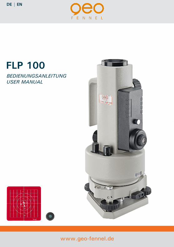
BEDIENUNGSANLEITUNGUSER MANUAL
www.geo-fennel.de
DE | EN
FLP 100
2
Sehr geehrter Kunde,
vielen Dank für das Vertrauen, das Sie uns beim Erwerb Ihres neuen geo-FENNEL-Gerätes entgegengebracht haben. Diese Anleitung wird Ihnen helfen, das Ge-rät sachgemäß zu bedienen. Bitte lesen Sie insbesondere die Sicherheitshinweise vor der Inbetriebnahme aufmerksam durch. Nur ein sachgerechter Gebrauch gewähr-leistet einen langen und zuverlässigen Betrieb.
geo-FENNELPresicion by tradition.
Dear customer,
Thank you for your confidence in us having purchased a geo-FENNEL-instrument.This manual will help you to operate the instrument appropriately. Please read the manual carefully - particularly the safety instructions.A proper use only guarantees a longtime and reliable operation.
geo-FENNELPrecision by tradition.
AABCCDDD
Inhaltsverzeichnis / Table of Contents
1. Technische Daten / Technical Specifications
2. Lieferumfang / Parts Included
3. Bedienelemente / Operational Elements
4. Bedienung / Operation of Instrument
5. Fehlerbehebung / Troubleshooting
6. Warn-/Sicherheitshinweise / Safety Instructions
7. Garantieerklärung / Warranty
8. Haftungserklärung / Exceptions from Responsibility
3
A
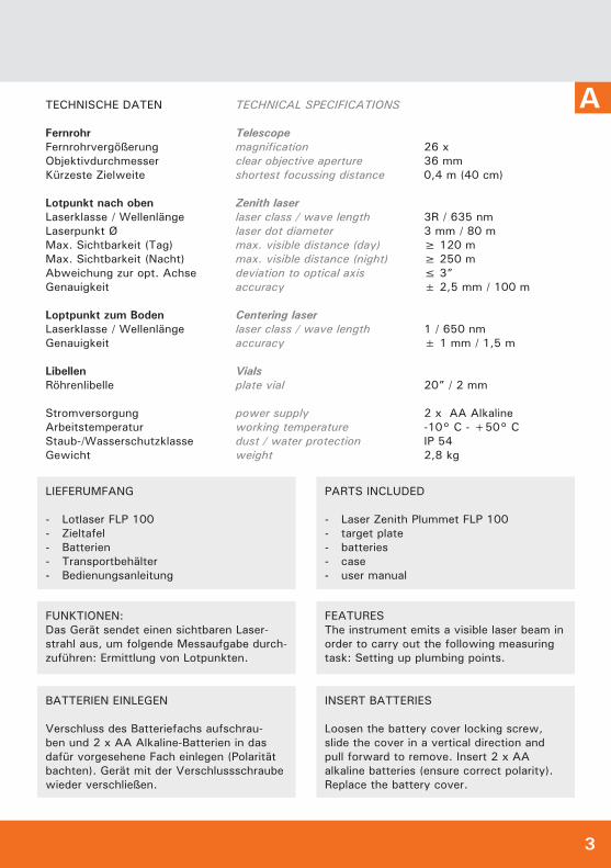
LIEFERUMFANG
- Lotlaser FLP 100 - Zieltafel - Batterien - Transportbehälter - Bedienungsanleitung
BATTERIEN EINLEGEN
Verschluss des Batteriefachs aufschrau-ben und 2 x AA Alkaline-Batterien in das dafür vorgesehene Fach einlegen (Polarität bachten). Gerät mit der Verschlussschraube wieder verschließen.
FUNKTIONEN:Das Gerät sendet einen sichtbaren Laser-strahl aus, um folgende Messaufgabe durch-zuführen: Ermittlung von Lotpunkten.
PARTS INCLUDED
- Laser Zenith Plummet FLP 100 - target plate - batteries - case - user manual
INSERT BATTERIES
Loosen the battery cover locking screw, slide the cover in a vertical direction and pull forward to remove. Insert 2 x AA alkaline batteries (ensure correct polarity). Replace the battery cover.
FEATURESThe instrument emits a visible laser beam in order to carry out the following measuring task: Setting up plumbing points.
26 x36 mm0,4 m (40 cm)
3R / 635 nm3 mm / 80 m≥ 120 m≥ 250 m≤ 3”± 2,5 mm / 100 m
1 / 650 nm± 1 mm / 1,5 m
20” / 2 mm
2 x AA Alkaline-10° C - +50° CIP 542,8 kg
TECHNISCHE DATEN
FernrohrFernrohrvergößerungObjektivdurchmesserKürzeste Zielweite
Lotpunkt nach obenLaserklasse / WellenlängeLaserpunkt ØMax. Sichtbarkeit (Tag)Max. Sichtbarkeit (Nacht)Abweichung zur opt. AchseGenauigkeit
Loptpunkt zum BodenLaserklasse / WellenlängeGenauigkeit
LibellenRöhrenlibelle
StromversorgungArbeitstemperaturStaub-/WasserschutzklasseGewicht
TECHNICAL SPECIFICATIONS
Telescopemagnificationclear objective apertureshortest focussing distance
Zenith laserlaser class / wave lengthlaser dot diametermax. visible distance (day)max. visible distance (night)deviation to optical axisaccuracy
Centering laserlaser class / wave lengthaccuracy
Vialsplate vial
power supplyworking temperaturedust / water protectionweight
4
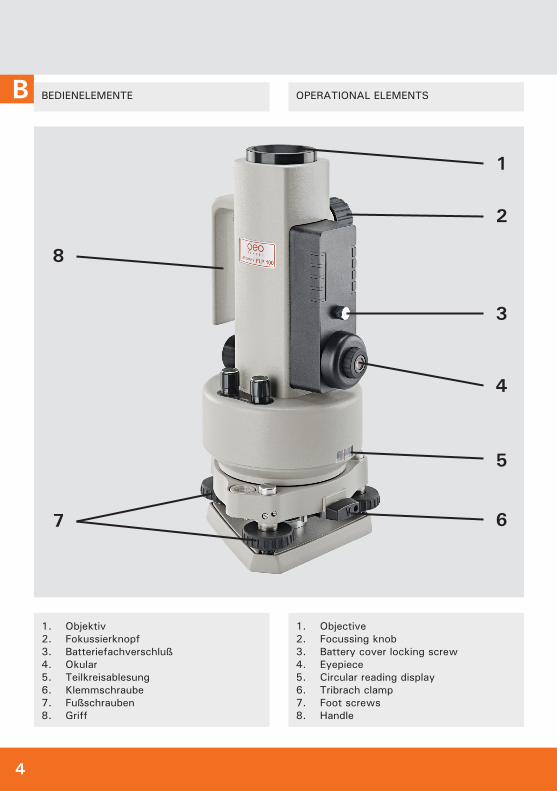
B BEDIENELEMENTE
1. Objektiv2. Fokussierknopf3. Batteriefachverschluß4. Okular5. Teilkreisablesung6. Klemmschraube7. Fußschrauben8. Griff
OPERATIONAL ELEMENTS
1. Objective2. Focussing knob3. Battery cover locking screw4. Eyepiece5. Circular reading display6. Tribrach clamp7. Foot screws8. Handle
4
1
2
3
5
67
8
5
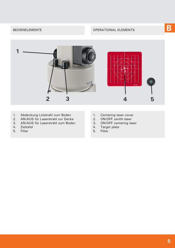
BBEDIENELEMENTE
1. Abdeckung Lotstrahl zum Boden2. AN/AUS für Laserstrahl zur Decke3. AN/AUS für Laserstrahl zum Boden4. Zieltafel5. Filter
1. Centering laser cover2. ON/OFF zenith laser3. ON/OFF centering laser4. Target plate5. Filter
OPERATIONAL ELEMENTS
3 4 52
1
6
C
GERÄT EINSCHALTEN
BEACHTE Beim Einschalten des Laserstrahls zur Decke unbedingt Filter aufsetzen.
Schalter AN/AUS Laserstrahl zur Decke und / oder AN/AUS Laserstrahl zum Boden bis zum Klick nach rechts drehen. Der Laserstrahl ist nun eingeschaltet. Um die Intensität des Laserstrahls zu verstärken, Knopf weiter nach rechts drehen. Knopf wieder nach links bis zum Klick drehen, um Laserstrahl wieder auszuschalten.
Der Laserstrahl ist bei Tageslicht bis ca. 120 m und bei dunkleren Bedingungen bis ca. 250 m sichtbar. Über diese Entfer-nungen hinaus kann das Gerät optisch - also über Fadenkreuz und Zieltafel - eingesetzt werden.
POWER ON/OFF
N.B.When using the zenith laser it is essential the filter is used at all times.
To Power-On the zenith laser and centring laser rotate the switches clockwise until you hear a “click“. The laser beams are now switched on and any further clockwise rotation will increase the intensity of the laser beams. To Power-Off the laser beams rotate the switches anti-clockwise until you hear a “click”.
The visible distance of the zenith laser beam is up to 120 m in daylight conditions and 250m in dark conditions. For all measurements exceeding these distances the instrument must be used optically.
BEDIENUNG
Gerät aufstellenGerät direkt auf dem Boden aufstellen oder auf dem Stativ befestigen.
Gerät möglichst waagerecht aufstellen und die Dosenlibelle mit Hilfe der Fußschrauben des Dreifußes zentrieren. Röhrenlibelle mit Hilfe der Fußschrauben exakt zentrieren. Dabei Gerät jeweils um 90°, 180° und 270° drehen und Einstel-lung der Röhrenlibelle überprüfen und ggf. korrigieren. Nur wenn beide Libellen exakt eingestellt sind, kann das Gerät genau arbeiten.
OPERATION
Set up instrument Position the instrument on a solid stable surface or a suitable tripod.
With the instrument as upright as possible use the footscrews to centralise the circular level.Rotate the instrument until the plate level is parallel to a line between two footscrews. Centre the plate level by using the same two footscrews. Rotate the instrument by 90°and centre the plate level once more using the third footscrew. Repeat this procedure until the plate level is perfectly centred in all positions. Optimum precision can only be achieved when the instrument is perfectly level.
7
C
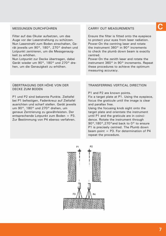
ÜBERTRAGUNG DER HÖHE VON DER DECKE ZUM BODEN
P1 und P2 sind bekannte Punkte. Zieltafel bei P1 befestigen, Fadenkreuz auf Zieltafel ausrichten und scharf stellen. Gerät jeweils um 90°, 180° und 270° drehen, um genaue Zentrierung zu gewährleisten. Der entsprechende Lotpunkt zum Boden = P3. Zur Bestimmung von P4 ebenso verfahren.
MESSUNGEN DURCHFÜHREN
Filter auf das Okular aufsetzen, um das Auge vor der Laserstrahlung zu schützen. Nun Laserstrahl zum Boden einschalten, Ge-rät jeweils um 90°, 180°, 270° drehen und Lotpunkt zentrieren, um die Messgenauig-keit zu erhöhen. Nun Lotpunkt zur Decke übertragen, dabei Gerät wieder um 90°, 180° und 270° dre-hen, um die Genauigkeit zu erhöhen.
TRANSFERRING VERTICAL DIRECTION
P1 and P2 are known points. Fix a target plate at P1. Using the eyepiece, focus the graticule until the image is clear and parallax free. Using the focusing knob sight onto the target plate and orientate the instrument until P1 and the graticule are in coinci-dence. Rotate the instrument through 90°,180°,270°and back to 0° to ensure P1 is precisely centred. The Plumb down beam point = P3. For determination of P4 repeat the procedure.
CARRY OUT MEASUREMENTS
Ensure the filter is fitted onto the eyepiece to protect your eyes from laser radiation. Power-On the centring laser and rotate the instrument 360° in 90° increments to check the plumb down beam is exactly centred. Power-On the zenith laser and rotate the instrument 360° in 90° increments. Repeat these procedures to achieve the optimum measuring accuracy.
8
C JUSTIERUNG
Das Gerät sollte regelmäßig auf seine Ge-nauigkeit überprüft werden.
JUSTIERUNG DER RÖHRENLIBELLE
Gerät auf einem Stativ befestigen und wie folgt vorgehen:
• Gerät grob über der Dosenlibelle zent-rieren
• Zwei Schrauben des Dreifußes lösen und die Blase der Dosenlibelle Richtung Zentrum bewegen
• Dritte Schraube lösen und die Blase der Dosenlibelle zentrieren
• Gerät über die Röhrenlibelle zentrieren• Klemmschraube am Dreifuß lösen,
dann zwei Schrauben des Dreifußes lösen und die Blase der Röhrenlibelle zentrieren
• Gerät um 90° drehen, dritte Schraube am Dreifuß lösen und Blase der Röhren-libelle zentrieren
• Vorgang in 90°-Schritten wiederholen bis die Röhrenlibelle zentriert ist
• Schrauben und Klemmschraube wieder festziehen
JUSTIERUNG DER DOSENLIBELLE
Zentrierung der Dosenlibelle überprüfen; wenn die Blase nicht zentriert ist, diese mit Hilfe des mitgelieferten Metallstifts zentrieren.
ADJUSTMENT
The user is expected to carry out periodic checks of the instrument‘s accuracy.
PLATE LEVEL ADJUSTMENT
Secure the instrument onto a suitable tripod and proceed, as follows:
• Level the instrument with the circular bubble
• Rotate the instrument until the plate level is parallel to a line between two footscrews
• Using these two footscrews centralise the plate level bubble
• Now rotate the instrument 90° and centralise the bubble once more using the third footscrew
• Repeat the procedure and the bubble should be central in all positions. If not, proceed, as follows:
• Rotate the instrument until the plate level is parallel to a line between two footscrews. Using these two footscrews centralise the plate level bubble
• Rotate the instrument exactly 180° and note the position of the plate level bubble
• If the bubble is not central the plate level should be adjusted
• Remove half of the deviation on the plate level adjusting screw with the ad-justing pin supplied in the tool kit and half of the deviation with a footscrew
• Repeat the above procedures until the plate level is centred in all positions.
ADJUSTMENT OF CIRCULAR VIAL
With the instrument leveled as detailed in the previous paragraph check if circular vial is centred. If not centre by means of the adjusting pin supplied in the tool kit.
9
CJUSTIERUNG DES LOTSTRAHLS ZUM BODEN
Gerät auf einem Stativ befestigen und Zieltafel darunter anbringen. Lotstrahl zum Boden einschalten und Gerät drehen. Wenn der Lotpunkt nicht mit dem Fadenkreuz der Zieltafel übereinstimmt (d. h. Lotpunkt wan-dert und bleibt nicht im Mittelpunkt), muss der Lotstrahl justiert werden.
Dazu wie folgt vorgehen:Abdeckung des Lotstrahls zum Boden öffnen und die Schrauben mit Hilfe des Metallstifts justieren, bis der Lotpunkt beim Drehen den Mittelpunkt hält. Schrauben wieder anziehen und Abdeckung schließen
CENTRING LASER ADJUSTMENT
With the instrument on a suitable tripod Power-On the centring laser.Rotate the footscrews to centre the laser beam exactly over a target plate. When the instrument is rotated through 360° the laser beam should stay centred in all positions. If not, the centring laser should be adjusted.
Adjust as follows:Unscrew and remove the centring laser cover. Adjust the screws using the adju-sting pin supplied in the tool kit until the laser beam coincides with the center of the target plate.Check by rotating the instrument 360° and ensure the adjusting screws are secure with equal tension.We suggest these adjustments are carried out by a suitably trained engineer.
10
C
1. Gerät lässt sich nicht einschalten:1. Instrument will not power on: > Batterie ist leer > Batterie ersetzen > Battery power is low > replace batteries oder / or > Gerät ist defekt > Gerät zur Reparatur einsenden > Instrument defect > contact your service provider
2. Laserintensität lässt sich nicht regulieren:2. Laser intensity cannot be adjusted: > Knopf ist defekt > Gerät zur Reparatur einsenden > faulty switch > contact your service provider oder / or > Platine ist defekt > Gerät zur Reparatur einsenden > PCB defect > contact your service provider3. Sichtbarkeit des Lasers ist schwach:3. Visibility of laser beam is weak: > Batterie ist leer > Batterie ersetzen > Battery power is low > replace batteries oder / or > Laserdiode ist defekt > Gerät zur Reparatur einsenden > Laser diode defect > contact your service provider
4. Laserpunkt ist zu groß:4. Laser point is too large: > Fokussierung ist nicht in Ordnung > justieren gemäß Anleitung > focussing error> adjust according to user manual oder / or > Laserpunkt und Optik sind nicht konzentrisch > justieren gemäß Anleitung > Optical axis is not parfocalized with collimation axis > adjust according to user manual
5. Röhrenlibelle lässt sich nicht zentrieren:5. Plate level cannot be centred: >Röhrenlibelle ist nicht lotrecht zur Vertikalachse> justieren gemäß Anleitung >Plate level is not perpendicular to vertical axis> adjust according to user manual
6. Laserpunkt bewegt sich beim Umschlag:6. Laser dot moves when instrument is rotated: > Laserachse und Optik sind nicht fokussiert> justieren gemäß Anleitung > Laser and optical axis are not parfocal > adjsut according to user manual
FEHLERANZEIGE/-BEHEBUNG TROUBLESHOOTING
11
C
UMGANG UND PFLEGE
Messinstrumente generell sorgsam behan-deln. Nach Benutzung mit weichem Tuch reinigen (ggfs. Tuch in etwas Wasser trän-ken). Wenn das Gerät feucht war, sorgsam trocknen. Erst in den Koffer oder die Tasche packen, wenn es absolut trocken ist. Trans-port nur in Originalbehälter oder -tasche.
CARE AND CLEANING
Handle measuring instruments with care. Clean with soft cloth only after any use. If necessary damp cloth with some water. If instrument is wet clean and dry it carefully. Pack it up only if it is perfectly dry. Trans-port in original container / case only.
UMSTÄNDE, DIE DAS MESSERGEBNIS VERFÄLSCHEN KÖNNEN
Messungen durch Glas- oder Plastikschei-ben; verschmutzte Laseraustrittsfenster; Sturz oder starker Stoß. Bitte Genauigkeit überprüfen.
Große Temperaturveränderungen: Wenn das Gerät aus warmer Umgebung in eine kalte oder umgekehrt gebracht wird, vor Benut-zung einige Minuten warten.
SPECIFIC REASONS FOR ERRONEOUS MEASURING RESULTS
Measurements through glass or plastic win-dows; dirty laser emitting windows; after instrument has been dropped or hit. Please check accuracy.
Large fluctuation of temperature: If instru-ment will be used in cold areas after it has been stored in warm areas (or the other way around) please wait some minutes before carrying out measurements.
7. Laserstrahl ist schwach oder flackert:7. Laser beam is weak or flashes: > Batterie ist leer > Batterie ersetzen > Battery power is low > replace batteries oder / or > Diode ist defekt > Gerät zur Reparatur einsenden > Laser diode defect > contact your service provider oder / or > Platine ist defekt > Gerät zur Reparatur einsenden > PCB defect > contact your service provider
12
D WARN- UND SICHERHEITSHINWEISE
• Richten Sie den Laserstrahl nicht auf Personen oder Tiere und blicken Sie nicht selbst in den Laserstrahl.
• Das Messwerkzeug sollte nur von Personen bedient werden, die im Um-gang mit Lasergeräten vertraut sind. Laut IEC 60825-1:2008-5 gehört dazu u.a. die Kenntnis über die biologische Wirkung des Lasers auf das Auge und die Haut sowie die richtige Anwendung des Laserschutzes zur Abwendung von Gefahren.
• Keine Benutzung dieses Gerätes von Personen unter 18 Jahren
• Nicht in den direkten oder reflektierten Strahl blicken.
• Vermeiden Sie Reflexionen des Laser-strahls auf glatten Oberflächen wie Fenster oder Spiegel. Auch durch den reflektierten Laserstrahl ist eine Schädi-gung der Augen möglich.
• Falls Laserstrahlung der Klasse 3R ins Auge trifft, sind die Augen bewusst zu schließen und der Kopf sofort aus dem Strahl zu bewegen.
• Manipulationen (Änderungen) an der Lasereinrichtung sind unzulässig.
• Die zugängliche Laserstrahlung ist po-tentiell gefährlich für das Auge.
• Bei Anwendung von 3R-Lasern ist unbedingt die Anmeldung des Lasers und die Bestellung des Laserschutzbe-auftragten zwingend erforderlich.
• Vor der ersten Inbetriebnahme ist eine Betriebsanweisung zu erstellen!
• Diese Gebrauchsanleitung ist aufzu-bewahren und bei Weitergabe der Lasereinrichtung mitzugeben.
• Bei Nichtgebrauch ist das Lasergerät gegen Zugriff Unbefugter gesichert aufzubewahren.
• Kennzeichnen Sie den Bereich, in dem das Messwerkzeug verwendet wird, mit geeigneten Laser-Warnschildern. So vermeiden Sie, dass sich unbetei-ligte Personen in den Gefahrenbereich begeben. Sorgen Sie dafür, dass der
SAFETY INSTRUCTIONS
• Do not stare into the laser beam or point it towards people or animals.
• Do not aim the beam at reflective sur-faces such as windows or mirrors as reflected beams can be dangerous.
• The laser should only be operated by trained and qualified personnel. All users should be fully informed about the potential biological effects on the eyes and skin when using laser devices and be conversant with laser protec-tion regulations - as per IEC 60825-1:2008-5.
• Laser products should be restricted from persons under 18.
• In the event of a class 3R laser beam hitting the eye immediately close your eyes and turn your head away from the beam.
• Do not attempt to repair or adjust the laser device.
• The emitted laser radiation is potenti-ally dangerous to the eye.
• The use of class 3R laser products may require registration with a local au-thority and the appointment of a laser protection official.
• Do not operate the laser without first reading and understanding all the safety and technical data in the user manual.
• The user manual must always be kept with the instrument.
• The instrument should be kept from unauthorized use.
• Areas where these class 3R laser devices are being used should display the appropriate warning signs. This is to prevent unauthorized persons inavertently entering the working area. If necessary, ensure that the laser wor-king area is being guarded and/or shiel-ded. The limitation of laser radiation in controlled areas avoids eye injuries to external persons.
• The legal requirement for using class 3R laser product will vary from country
13
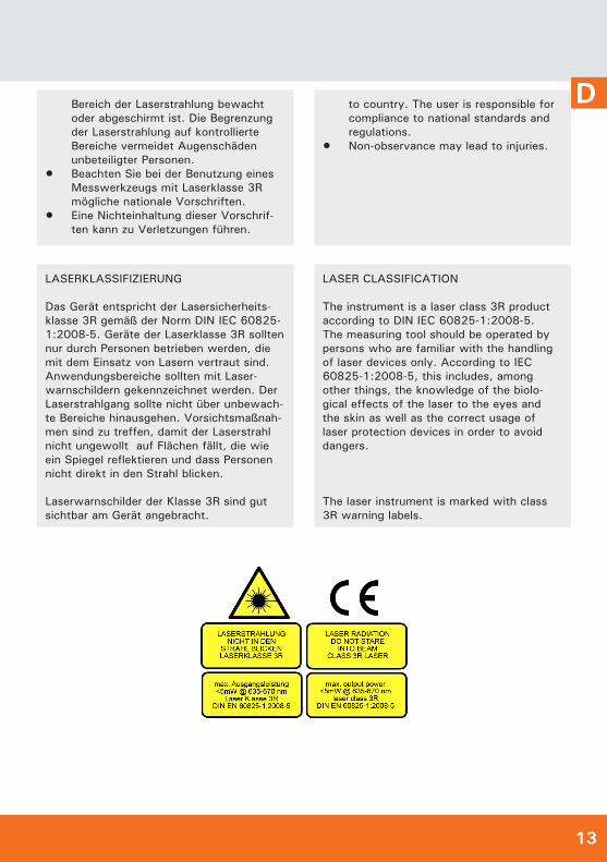
DBereich der Laserstrahlung bewacht oder abgeschirmt ist. Die Begrenzung der Laserstrahlung auf kontrollierte Bereiche vermeidet Augenschäden unbeteiligter Personen.
• Beachten Sie bei der Benutzung eines Messwerkzeugs mit Laserklasse 3R mögliche nationale Vorschriften.
• Eine Nichteinhaltung dieser Vorschrif-ten kann zu Verletzungen führen.
to country. The user is responsible for compliance to national standards and regulations.
• Non-observance may lead to injuries.
LASERKLASSIFIZIERUNG
Das Gerät entspricht der Lasersicherheits-klasse 3R gemäß der Norm DIN IEC 60825-1:2008-5. Geräte der Laserklasse 3R sollten nur durch Personen betrieben werden, die mit dem Einsatz von Lasern vertraut sind. Anwendungsbereiche sollten mit Laser-warnschildern gekennzeichnet werden. Der Laserstrahlgang sollte nicht über unbewach-te Bereiche hinausgehen. Vorsichtsmaßnah-men sind zu treffen, damit der Laserstrahl nicht ungewollt auf Flächen fällt, die wie ein Spiegel reflektieren und dass Personen nicht direkt in den Strahl blicken.
Laserwarnschilder der Klasse 3R sind gut sichtbar am Gerät angebracht.
LASER CLASSIFICATION
The instrument is a laser class 3R product according to DIN IEC 60825-1:2008-5.The measuring tool should be operated by persons who are familiar with the handling of laser devices only. According to IEC 60825-1:2008-5, this includes, among other things, the knowledge of the biolo-gical effects of the laser to the eyes and the skin as well as the correct usage of laser protection devices in order to avoid dangers.
The laser instrument is marked with class 3R warning labels.
14
D
GARANTIE
Die Garantiezeit beträgt zwei (2) Jahre, beginnend mit dem Verkaufsdatum. Die Garantie erstreckt sich nur auf Mängel wie Material-oder Herstellungsfehler, sowie die Nichterfüllung zugesicherter Eigenschaften. Ein Garantieanspruch besteht nur bei be-stimmungsgemäßer Verwendung. Mechani-scher Verschleiß und äußerliche Zerstörung durch Gewaltanwendung und Sturz unter-liegen nicht der Garantie. Der Garantiean-spruch erlischt, wenn das Gehäuse geöffnet wurde. Der Hersteller behält sich vor, im Garantiefall die schadhaften Teile instand zu setzen bzw. das Gerät gegen ein gleiches oder ähnliches (mit gleichen technischen Daten) auszutauschen. Ebenso gilt das Aus-laufen der Batterie nicht als Garantiefall.
WARRANTY
This product is warranted by the manufac-turer to the original purchaser to be free from defects in material and workmanship under normal use for a period of two (2) years from the date of purchase. During the warranty period, and upon proof of purchase, the product will be repaired or replaced (with the same or similar model at manufacturers option), without charge for either parts or labour. In case of a defect please contact the dealer where you origi-nally purchased this product. The warranty will not apply to this product if it has been misused, abused or altered. Without limiting the foregoing, leakage of the battery, ben-ding or dropping the unit are presumed to be defects resulting from misuse or abuse.
ELEKTROMAGNETISCHE VERTRÄGLICH-KEIT
Es kann nicht generell ausgeschlossen werden, dass das Gerät andere Geräte stört (z.B. Navigationseinrichtungen);durch andere Geräte gestört wird (z.B. elek-tromagnetische Strahlung bei erhöhter Feld-stärke z.B. in der unmittelbaren Nähe von Industrieanlagen oder Rundfunksendern).
ELECTROMAGNETIC ACCEPTABILITY (EMC)
It cannot be completely excluded that this instrument will disturb other instruments (e.g. navigation systems);will be disturbed by other instruments (e.g. intensive electromagnetic radiation nearby industrial facilities or radio transmitters).
CE-KONFORMITÄT
Das Gerät hat das CE-Zeichen gemäß der Norm EN 61326-1:2006.
CE-CONFORMITY
Instrument has CE-mark according to EN 61326-1:2006.
15
DHAFTUNGSAUSSCHLUSS
Der Benutzer dieses Produktes ist ange-halten, sich exakt an die Anweisungen der Bedienungsanleitung zu halten. Alle Geräte sind vor der Auslieferung genauestens überprüft worden. Der Anwender sollte sich trotzdem vor jeder Anwendung von der Genauigkeit des Gerätes überzeugen.Der Hersteller und sein Vertreter haften nicht für fehlerhafte oder absichtlich falsche Verwendung sowie daraus eventuell resul-tierende Folgeschäden und entgangenen Gewinn.Der Hersteller und sein Vertreter haften nicht für Folgeschäden und entgangenen Gewinn durch Naturkatastrophen wie z.B. Erdbeben, Sturm, Flut, usw. sowie Feuer, Unfall, Eingriffe durch Dritte oder einer Verwendung außerhalb der üblichen Einsatz-bereiche.Der Hersteller und sein Vertreter haften nicht für Schäden und entgangenen Gewinn durch geänderte oder verlorene Daten, Un-terbrechung des Geschäftsbetriebes usw., die durch das Produkt oder die nicht mögli-che Verwendung des Produktes verursacht wurden.Der Hersteller und sein Vertreter haften nicht für Schäden und entgangenen Gewinn resultierend aus einer nicht anleitungsgemä-ßen Bedienung.Der Hersteller und sein Vertreter haften nicht für Schäden, die durch unsachgemäße Verwendung oder in Verbindung mit Produk-ten anderer Hersteller verursacht wurden.
EXCEPTIONS FROM RESPONSIBILITY
The user of this product is expected to follow the instructions given in operators’ manual. Although all instruments left our warehouse in perfect condition and adjustment the user is expected to carry out periodic checks of the product’s accuracy and general performance.The manufacturer, or its representatives, assumes no responsibility of results of a faulty or intentional usage or misuse including any direct, indirect, consequential damage, and loss of profits. The manufacturer, or its representatives, assumes no responsibility for consequential damage, and loss of profits by any disaster (earthquake, storm, flood etc.), fire, accident, or an act of a third party and/or a usage in other than usual conditions.The manufacturer, or its representatives, assumes no responsibility for any damage, and loss of profits due to a change of data, loss of data and interruption of business etc., caused by using the product or an unusable product. The manufacturer, or its representatives, assumes no responsibility for any damage, and loss of profits caused by usage other than explained in the user manual.The manufacturer, or its representatives, assumes no responsibility for damage caused by wrong movement or action due to connecting with other products.

geo-FENNEL GmbHKupferstraße 6D-34225 BaunatalTel. +49 561 / 49 21 45Fax +49 561 / 49 72 [email protected]
Technische Änderungen vorbehalten.All instruments subject to technical changes.
Precision by tradition.
07/2012