Embed Size (px)
Citation preview
AWZM.120.12.2008
Dr.-Ing. habil. Jörg Wollnack
Hydraulische Systeme
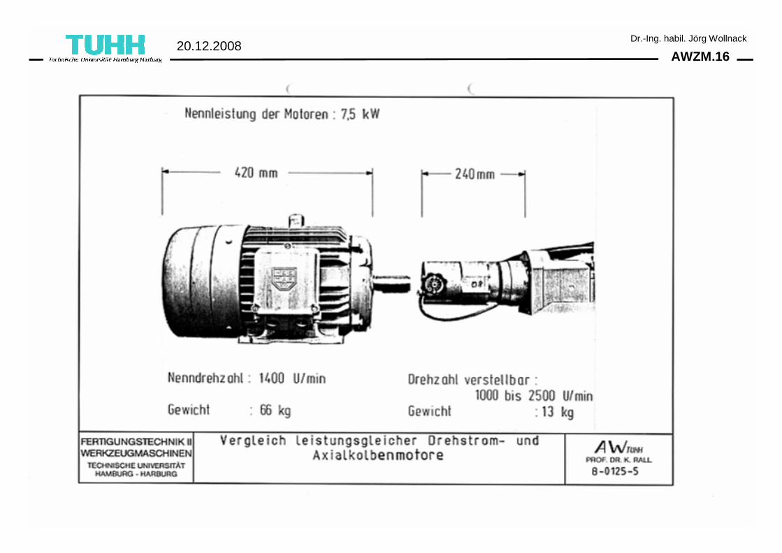
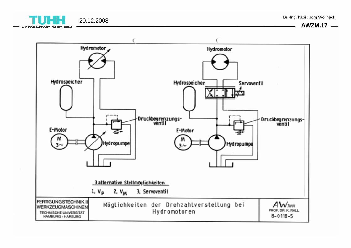
AWZM.220.12.2008
Dr.-Ing. habil. Jörg Wollnack
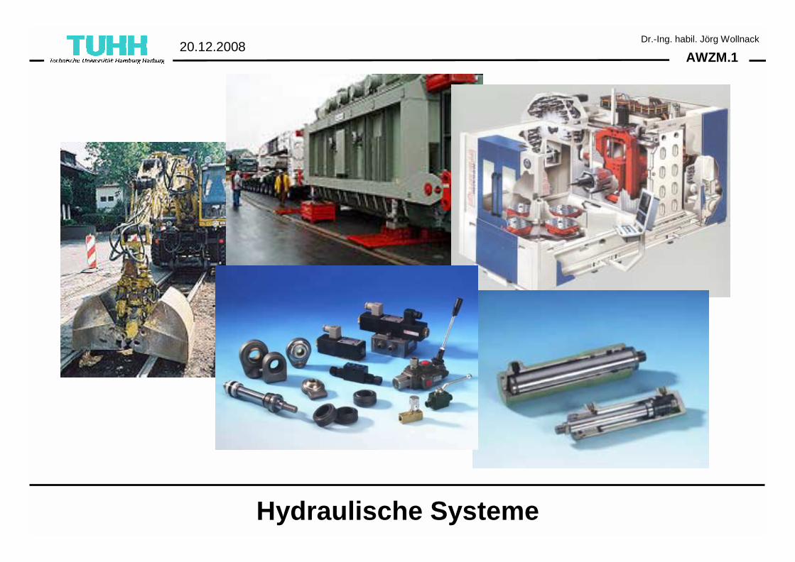
Hydraulische Motoren
AWZM.320.12.2008
Dr.-Ing. habil. Jörg Wollnack
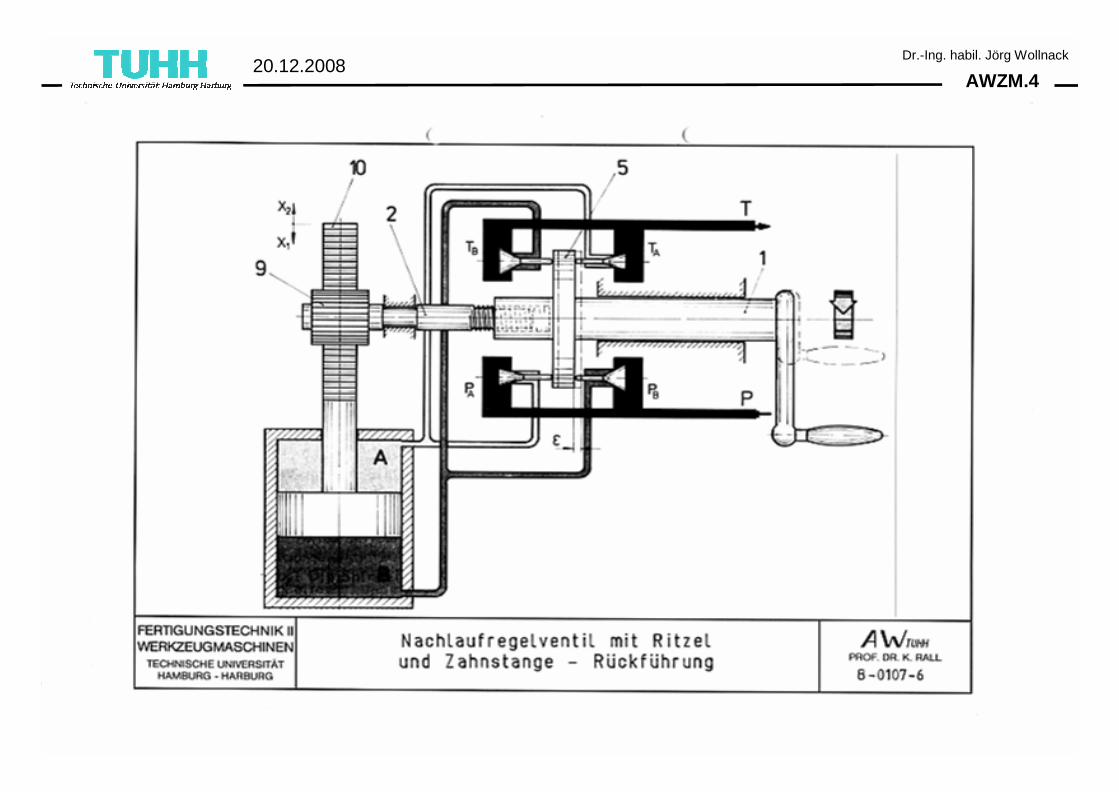
AWZM.420.12.2008
Dr.-Ing. habil. Jörg Wollnack
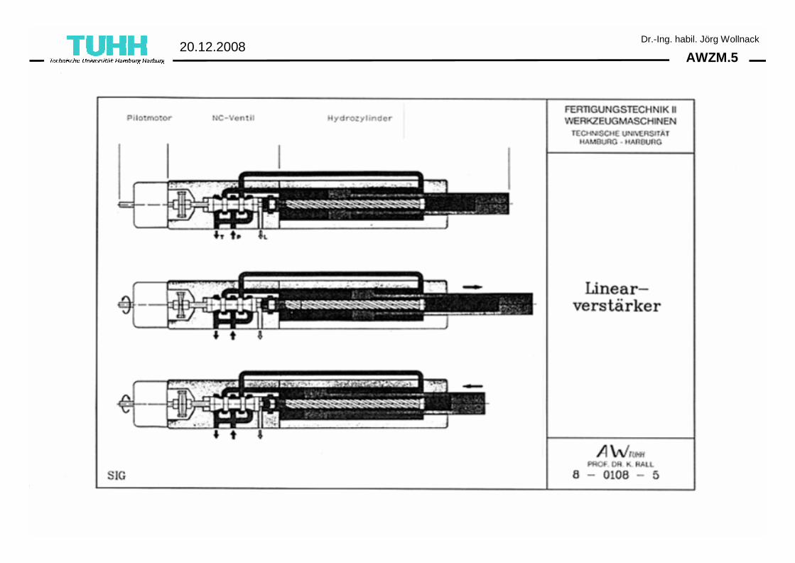
AWZM.520.12.2008
Dr.-Ing. habil. Jörg Wollnack
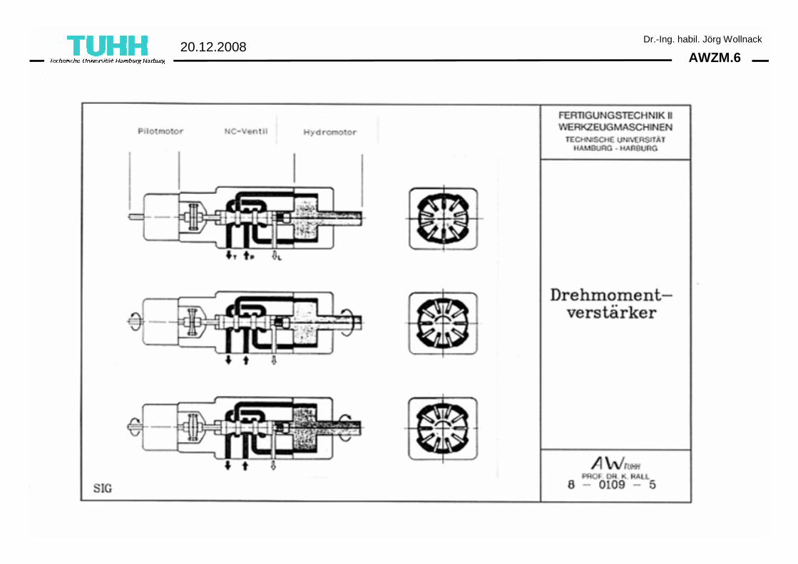
AWZM.620.12.2008
Dr.-Ing. habil. Jörg Wollnack
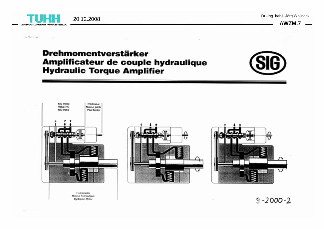
AWZM.720.12.2008
Dr.-Ing. habil. Jörg Wollnack
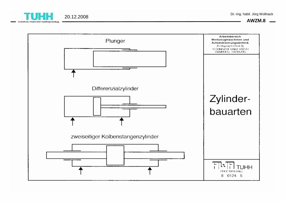
AWZM.820.12.2008
Dr.-Ing. habil. Jörg Wollnack
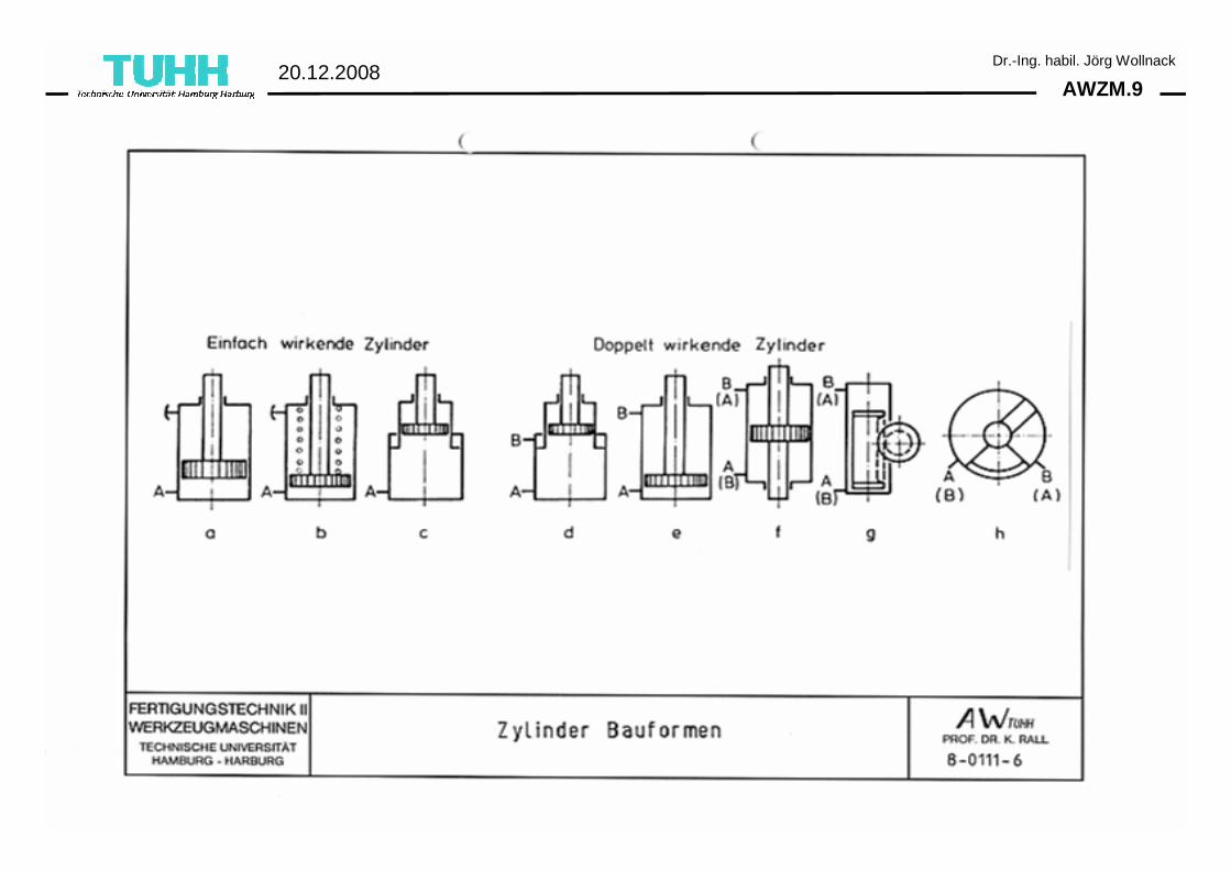
AWZM.920.12.2008
Dr.-Ing. habil. Jörg Wollnack
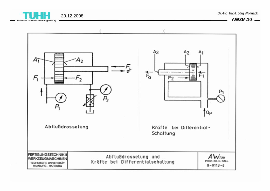
AWZM.1020.12.2008
Dr.-Ing. habil. Jörg Wollnack
AWZM.1120.12.2008
Dr.-Ing. habil. Jörg Wollnack
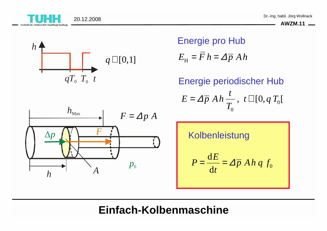
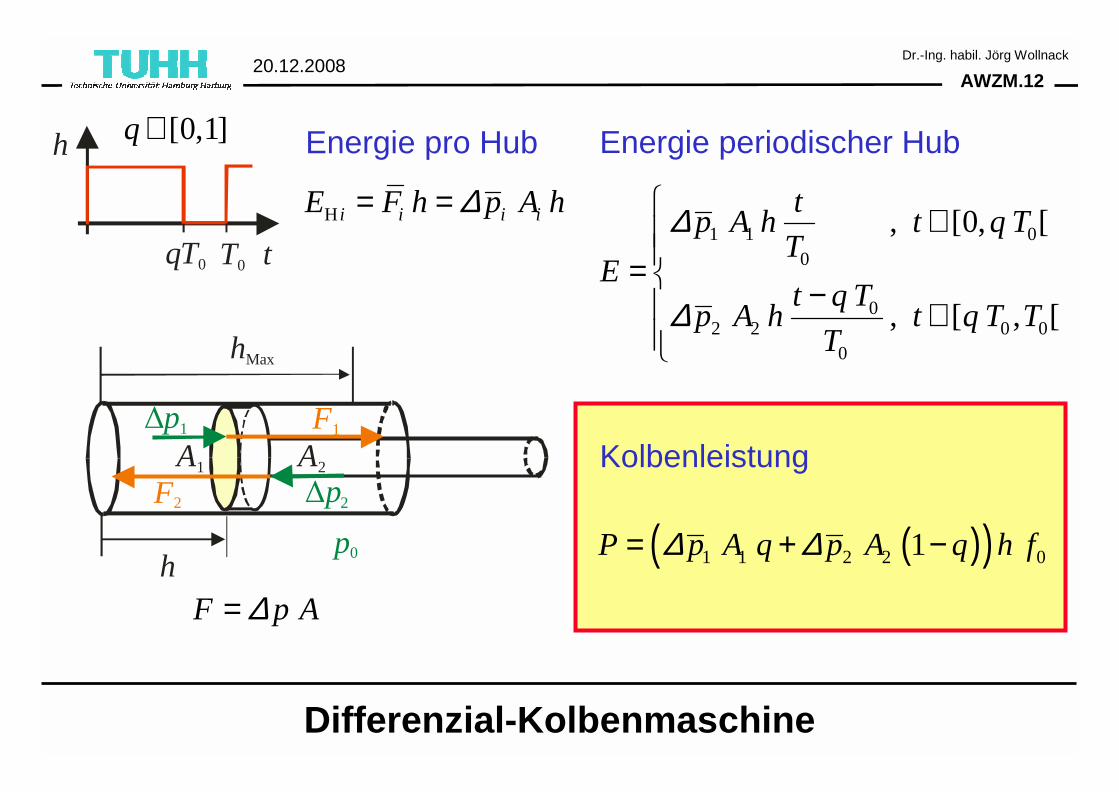
∆p
Ah
hMax
F
p0
F p A∆=
HE F h p Ah∆= =
00
, [0, [t
E p Ah t q TT
∆= ∈
0
d
d
EP p Ah q f
t∆= =
Einfach-Kolbenmaschine
Energie pro Hub
Energie periodischer Hub
Kolbenleistung
T0qT0 t
h
[0,1]q ∈
AWZM.1220.12.2008
Dr.-Ing. habil. Jörg Wollnack
∆p1
∆p2
A1
h
hMax
A2
F1
F2
p0
F p A∆=
H i i i iE F h p A h∆= =1 1 0
0
02 2 0 0
0
, [0, [
, [ , [
tp A h t q T
TE
t q Tp A h t q T T
T
∆
∆
∈= − ∈
( )( )1 1 2 2 01P p A q p A q h f∆ ∆= + −
Differenzial-Kolbenmaschine
Energie pro Hub Energie periodischer Hub
Kolbenleistung
T0qT0 t
h [0,1]q ∈
AWZM.1320.12.2008
Dr.-Ing. habil. Jörg Wollnack
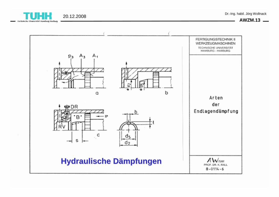
Hydraulische DHydraulische Däämpfungenmpfungen
AWZM.1420.12.2008
Dr.-Ing. habil. Jörg Wollnack
•• KompressibilitKompressibilitäät der Druckflt der Druckflüüssigkeit ssigkeit ⇒ Volumenänderung durch Druckänderung reduziert die Steifigkeit und beeinflusst die Lage.
•• VolumenVolumenäänderungen durch Nachgiebigkeit von Rohren, nderungen durch Nachgiebigkeit von Rohren, SchlSchlääuchen und Zylinderwuchen und Zylinderwäänden nden ⇒ Folgen analog zurKompressibilität.
•• Luft im System Luft im System ⇒ Setzt Kompressibilität der Druckflüssigkeit stark herauf⇒ Geringe Steifigkeit fördert Stick-Slip,⇒ Systemdämpfung signifikant reduziert, ⇒ Beeinflusst Eigenfrequenzen des Zylinderantriebs deutlich und⇒ bewirkt schlechte Wiederholgenauigkeit
Störeinflüsse in Hydrauliksystemen I
AWZM.1520.12.2008
Dr.-Ing. habil. Jörg Wollnack
•• DruckstDruckstößöße bei schnellem, schlagartigem Umsteuern oder e bei schnellem, schlagartigem Umsteuern oder plplöötzlichen Schlietzlichen Schließßen von Ventilen en von Ventilen (Kinetische Energie des strömenden Mediums führt zu Druckänderungen; Impuls der Strömung).
•• EntspannungsschlEntspannungsschlääge ge (Hochgespannte Medien mit großem Volumen hochdynamisch entspannt werden).
Störeinflüsse in Hydrauliksystemen II
AWZM.1620.12.2008
Dr.-Ing. habil. Jörg Wollnack
AWZM.1720.12.2008
Dr.-Ing. habil. Jörg Wollnack
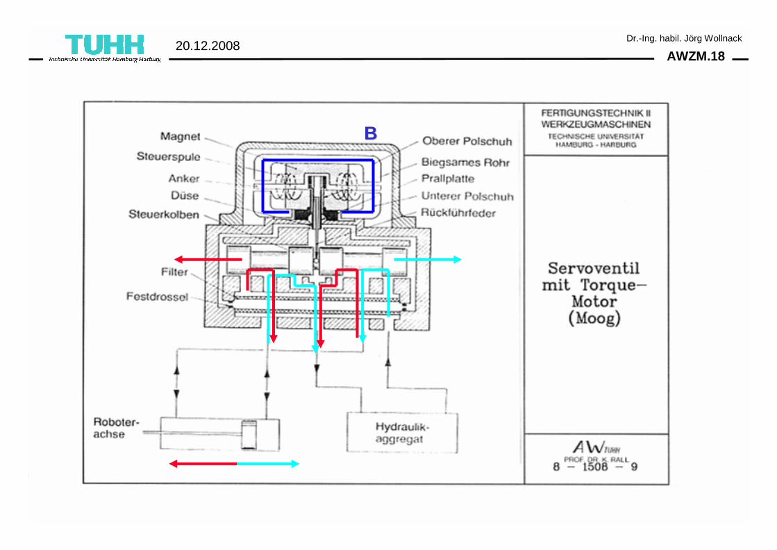
AWZM.1820.12.2008
Dr.-Ing. habil. Jörg Wollnack
BB
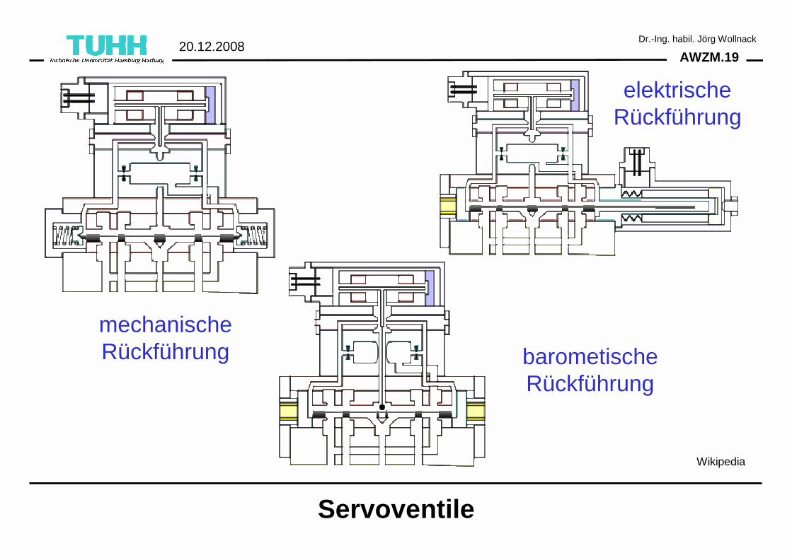
AWZM.1920.12.2008
Dr.-Ing. habil. Jörg Wollnack
Servoventile
mechanischeRückführung
elektrischeRückführung
barometischeRückführung
Wikipedia
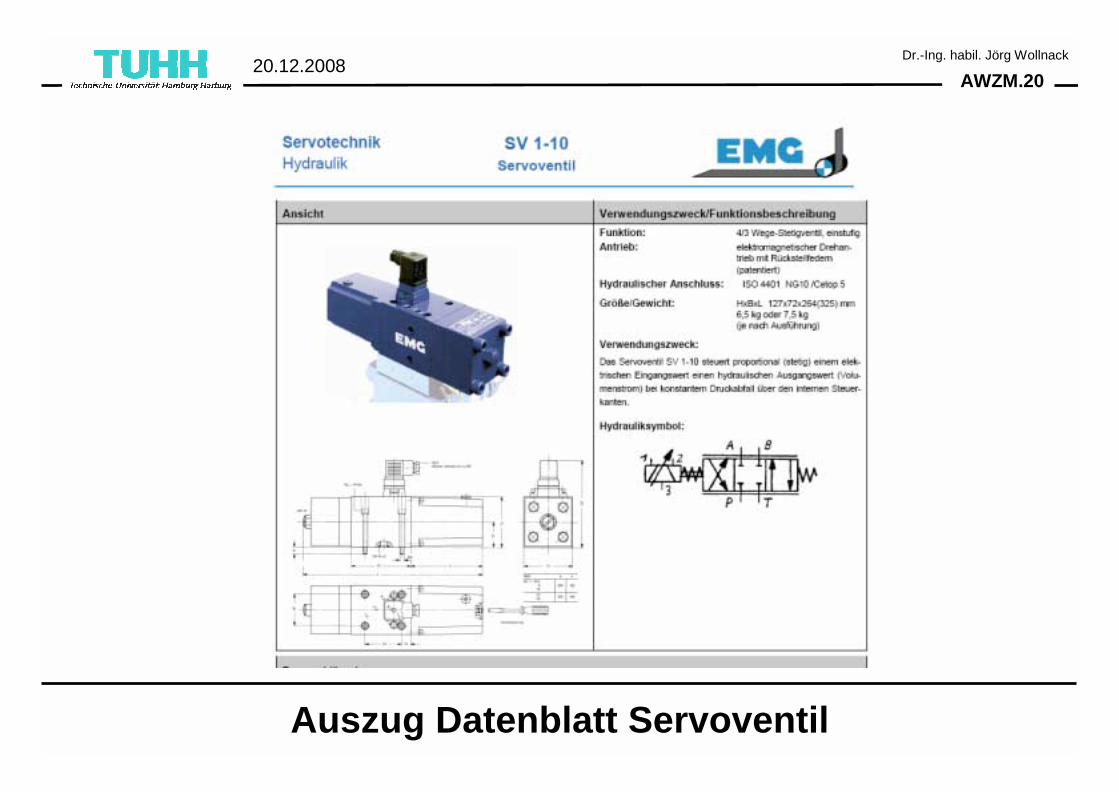
AWZM.2020.12.2008
Dr.-Ing. habil. Jörg Wollnack
Auszug Datenblatt Servoventil
AWZM.2120.12.2008
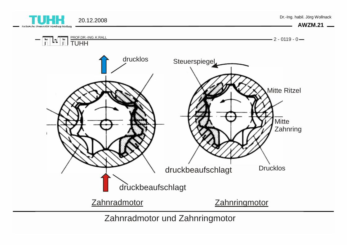
Dr.-Ing. habil. Jörg Wollnack
2 - 0119 - 0
Zahnradmotor und Zahnringmotor
TUHHPROF.DR.-ING. K.RALL
drucklos
Drucklos
druckbeaufschlagt
druckbeaufschlagt
Zahnradmotor Zahnringmotor
Steuerspiegel
Mitte Ritzel
MitteZahnring
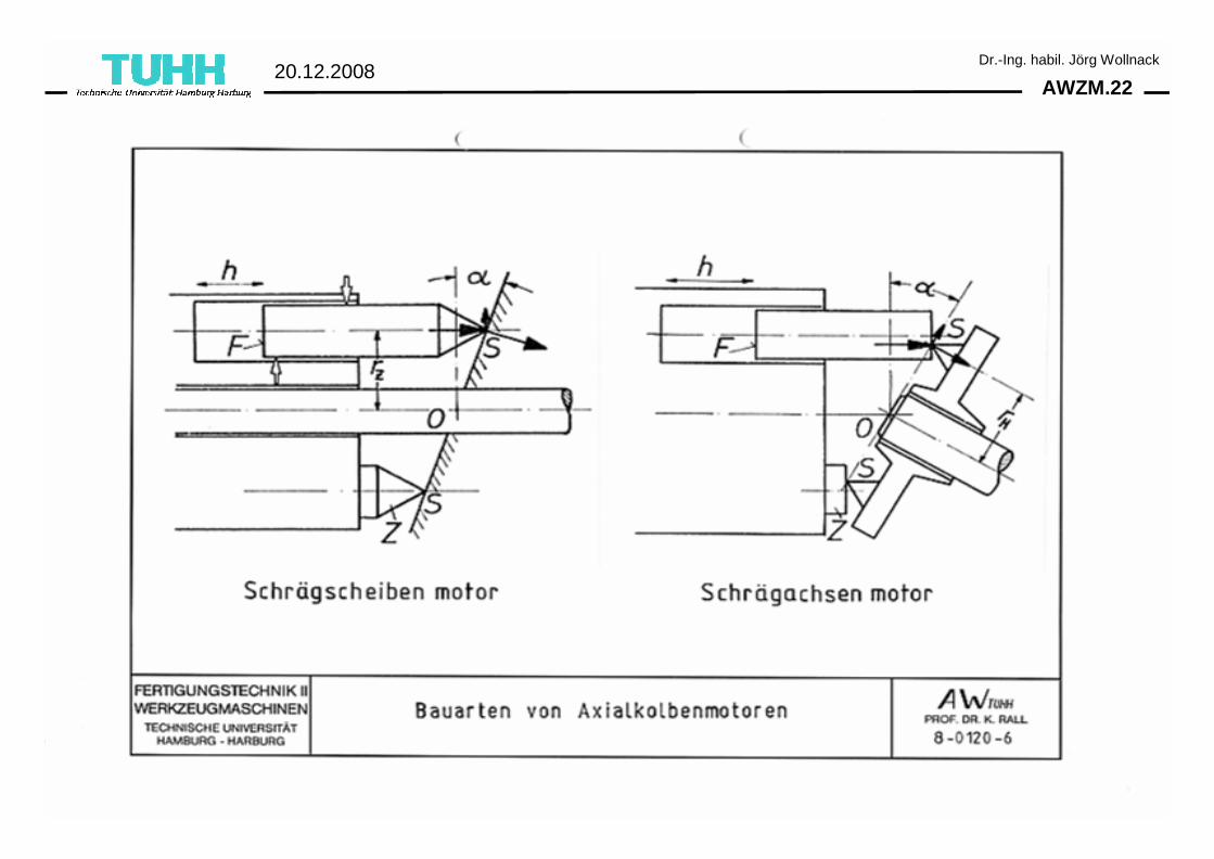
AWZM.2220.12.2008
Dr.-Ing. habil. Jörg Wollnack
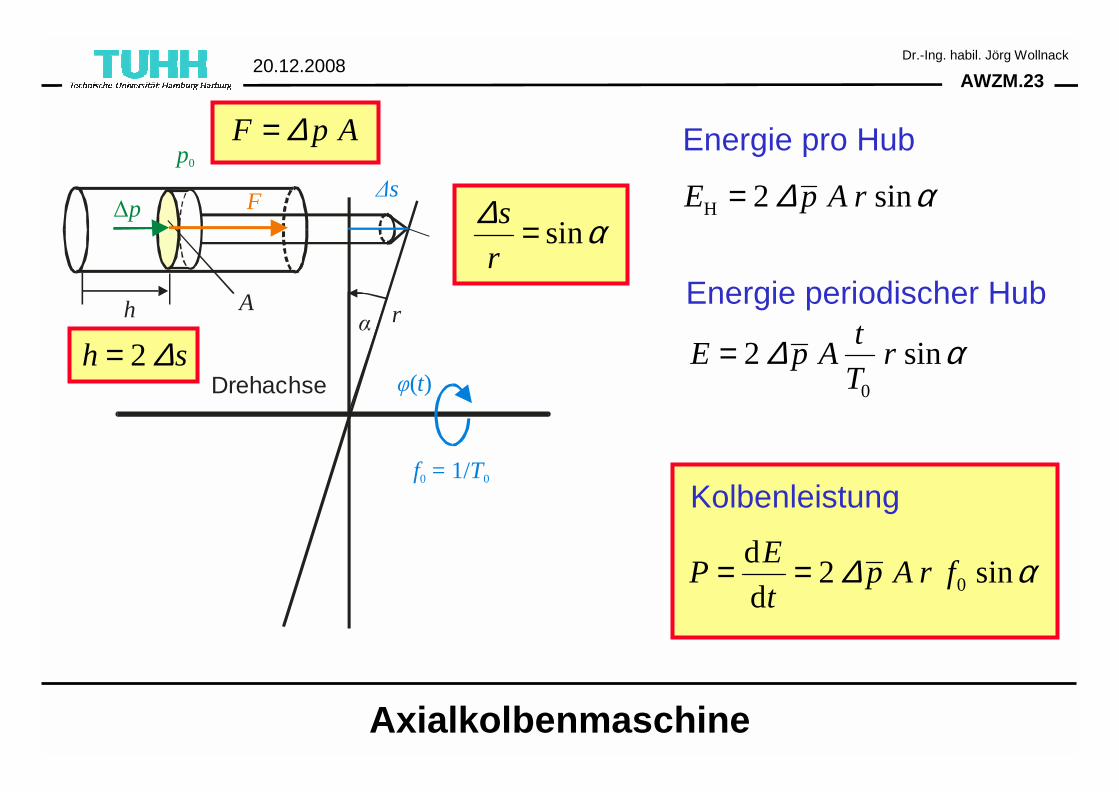
AWZM.2320.12.2008
Dr.-Ing. habil. Jörg Wollnack
∆p
Ah
F
p0
∆s
rα
Drehachse
f T0 0 = 1/
φ( )t2h s∆=
sins
r
∆ α=H 2 sinE p A r∆ α=
0
2 sint
E p A rT
∆ α=
0
d2 sin
d
EP p A r f
t∆ α= =
Axialkolbenmaschine
Energie pro Hub
Energie periodischer Hub
Kolbenleistung
F p A∆=
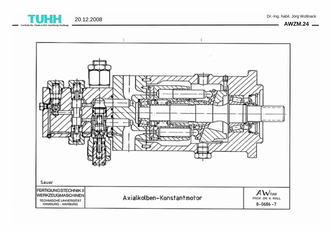
AWZM.2420.12.2008
Dr.-Ing. habil. Jörg Wollnack
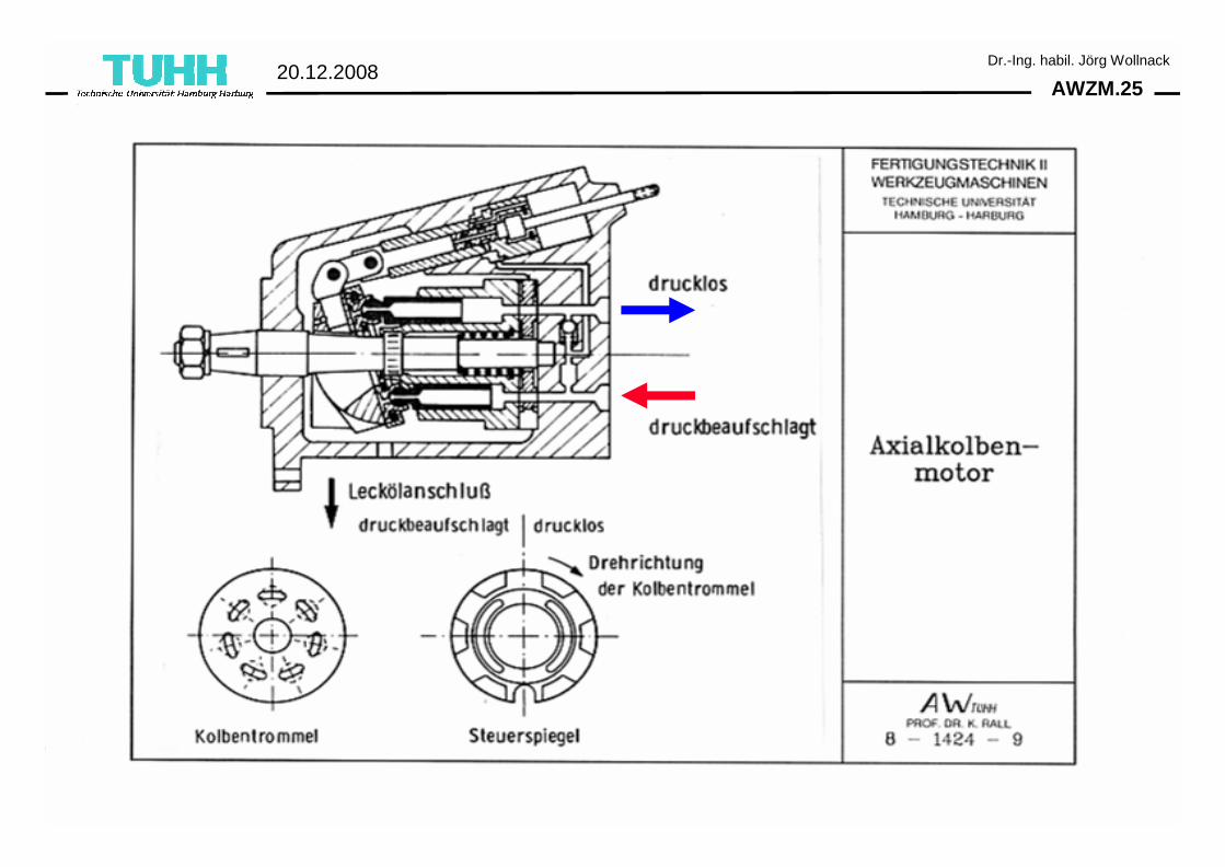
AWZM.2520.12.2008
Dr.-Ing. habil. Jörg Wollnack
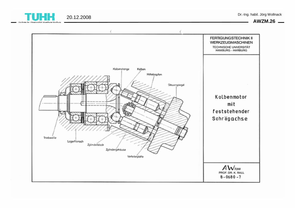
AWZM.2620.12.2008
Dr.-Ing. habil. Jörg Wollnack
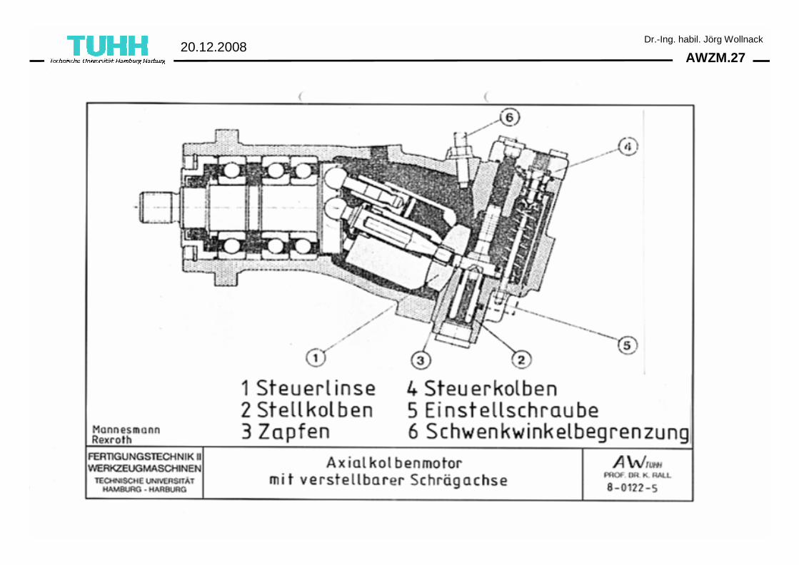
AWZM.2720.12.2008
Dr.-Ing. habil. Jörg Wollnack
AWZM.2820.12.2008
Dr.-Ing. habil. Jörg Wollnack
AWZM.2920.12.2008
Dr.-Ing. habil. Jörg Wollnack
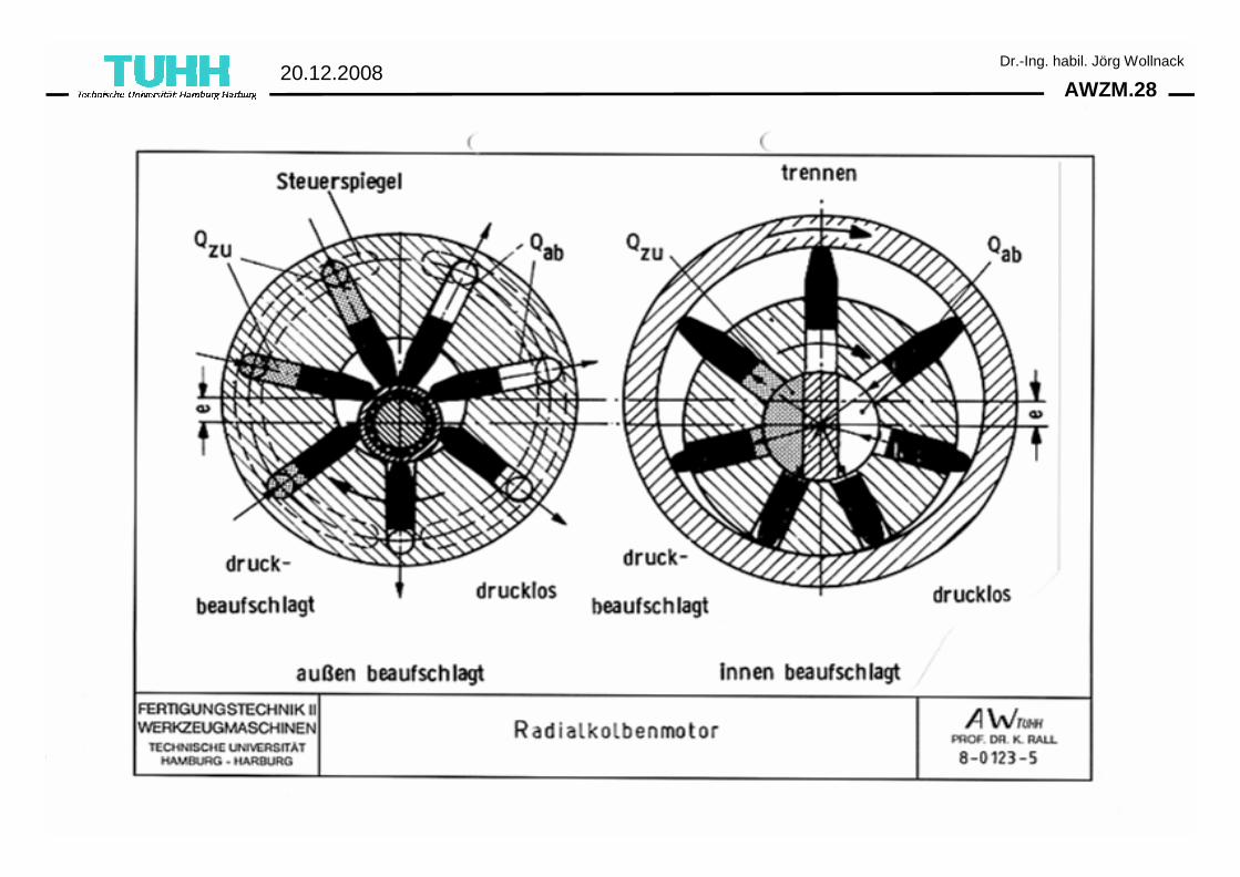
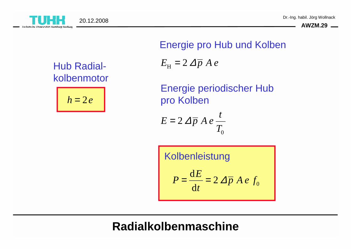
2h e=
H 2E p A e∆=
0
2t
E p A eT
∆=
0
d2
d
EP p A e f
t∆= =
Energie pro Hub und Kolben
Energie periodischer Hub pro Kolben
Kolbenleistung
Radialkolbenmaschine
Hub Radial-kolbenmotor
AWZM.3020.12.2008
Dr.-Ing. habil. Jörg Wollnack
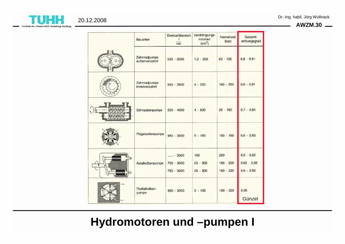
Hydromotoren und –pumpen I
Günzel
AWZM.3120.12.2008
Dr.-Ing. habil. Jörg Wollnack
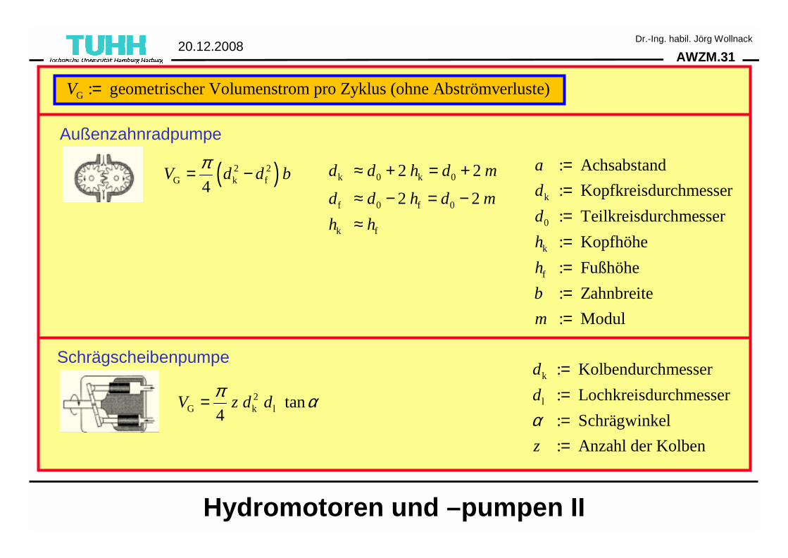
( )2 2G k f4
V d d bπ= −
2G k l tan
4V z d d
π α=
k 0 k 0
f 0 f 0
k f
2 2
2 2
d d h d m
d d h d m
h h
≈ + = +
≈ − = −≈
k
0
k
f
: Achsabstand
: Kopfkreisdurchmesser
: Teilkreisdurchmesser
: Kopfhöhe
: Fußhöhe
: Zahnbreite
: Modul
a
d
d
h
h
b
m
=======
k
l
: Kolbendurchmesser
: Lochkreisdurchmesser
: Schrägwinkel
: Anzahl der Kolben
d
d
z
α
====
Hydromotoren und –pumpen II
G : geometrischer Volumenstrom pro Zyklus (ohne Abströmverluste)V =
Außenzahnradpumpe
Schrägscheibenpumpe
AWZM.3220.12.2008
Dr.-Ing. habil. Jörg Wollnack
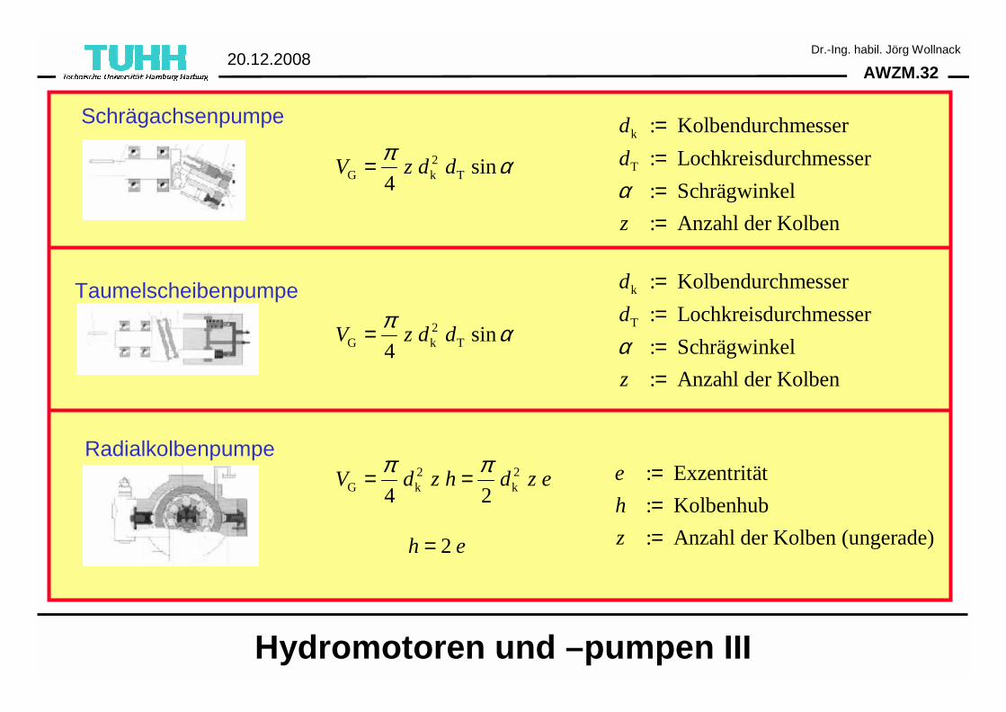
Hydromotoren und –pumpen III
2G k T sin
4V z d d
π α=
k
T
: Kolbendurchmesser
: Lochkreisdurchmesser
: Schrägwinkel
: Anzahl der Kolben
d
d
z
α
====
Schrägachsenpumpe
Taumelscheibenpumpe
2G k T sin
4V z d d
π α=
Radialkolbenpumpe2 2
G k k4 2V d z h d z e
π π= =
2h e=
: Exzentrität
: Kolbenhub
: Anzahl der Kolben (ungerade)
e
h
z
===
k
T
: Kolbendurchmesser
: Lochkreisdurchmesser
: Schrägwinkel
: Anzahl der Kolben
d
d
z
α
====
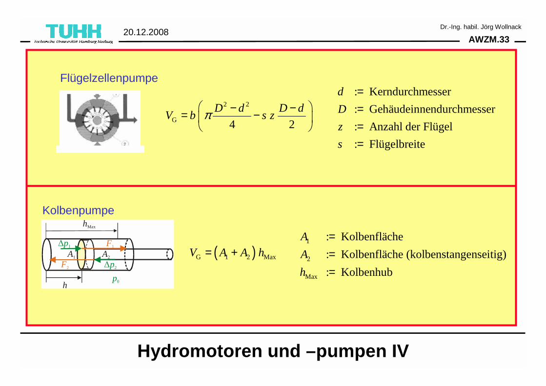
AWZM.3320.12.2008
Dr.-Ing. habil. Jörg Wollnack
2 2
G 4 2
D d D dV b s zπ − −= −
Flügelzellenpumpe: Kerndurchmesser
: Gehäudeinnendurchmesser
: Anzahl der Flügel
: Flügelbreite
d
D
z
s
====
∆p1
∆p2
A1
h
hMax
A2
F1
F2
p0
( )G 1 2 MaxV A A h= +1
2
Max
: Kolbenfläche
: Kolbenfläche (kolbenstangenseitig)
: Kolbenhub
A
A
h
===
Kolbenpumpe
Hydromotoren und –pumpen IV
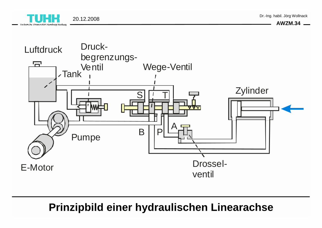
AWZM.3420.12.2008
Dr.-Ing. habil. Jörg Wollnack
Wege-Ventil
Pumpe
E-Motor
S
B PA
T
Drossel-ventil
Luftdruck
Tank
Druck-begrenzungs-Ventil
Zylinder
Prinzipbild einer hydraulischen Linearachse
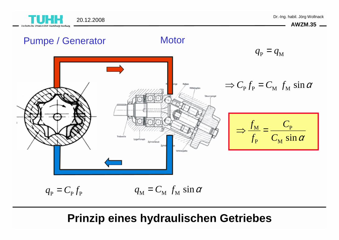
AWZM.3520.12.2008
Dr.-Ing. habil. Jörg Wollnack
Prinzip eines hydraulischen Getriebes
M M M sinq C f α=P P Pq C f=
P P M M sinC f C f α⇒ =
P Mq q=
M P
P M sin
f C
f C α⇒ =
Pumpe / Generator Motor