Embed Size (px)
Citation preview
Rückenschild für Ordner A4 (50 mm Rückenbreite); Zuschneiden auf 205 mm x 50 mm
Rückenschild für Ordner A4 (30 mm Rückenbreite); Zuschneiden auf 205 mm x 23 mm
AXD3-340.620.13.01.02 AXD3-340.620.13.01.02 AXD3-340.620.13.01.02 AXD3-340.620.13.01.02
Drucknummer zum Aufkleben
AXIOM Iconos R200 with fixed table heightOperator Manual
AXIOM Iconos R200 with fixed table heightOperator Manual
AXIOM Iconos R200 with fixed table heightOperator Manual
AXIOM Iconos R200 with fixed table heightOperator Manual

1
2
3
4
5
6
7
8
Safety
ystem Overview
ystem Operation
xamination
enerator
igital Image Processing
nterventional Application
S
S
E
G
D
I
AXIO
M
9
10
11
12
Operating ManualStands/Tube Supports
ucky Wall Unit
ystem Configuration/Options
ccessories
AXIOM Iconos R200B
S
A
with fixed table height
13
14
15
© Siemens AG 2002All rights reserved
Order No.: AXD3-340.620.13.01.02Printed in the Federal Republic of GermanyAG 12.2007
Contact Information:Siemens AG Siemens AG, Medical Solutions AXWittelsbacherplatz 2 Siemensstrasse 1DE-80333 Muenchen D-91301 ForchheimGermany Germany
Phone: +49 9191 18-0Internet: www.medical.siemens.com
Exposure Table
Addendum/Current Information
Technical Description
Important information from the manufacturerThis product is provided with a CE marking in accordance with theregulations stated in Appendix II of the Directive 93/42/EEC of June14th, 1993 concerning medical devices.
In accordance with Appendix IX of the Directive 93/42/EEC, thisdevice is assigned to class II b.
The CE marking applies only to medical devices which have beenput on the market according to the above-mentioned EC Directive.
Unauthorized changes to this product invalidate this declaration.
The original version of this manual was written in English.
Please observe the Safety Operator Manual.Important information is given there.
AXIOM Iconos R200Overall Table of Contents
Lists
Operator Manual
Overall Table of Contents
Part: Lists
Chapter: Overall Table of Contents....................................................................................................... 1
Part: System Overview
Chapter: System Description.................................................................................................................. 5
Application ............................................................................................................................................ 5Product description ............................................................................................................................... 5System configuration ............................................................................................................................ 6System overview .................................................................................................................................. 7Unit overview ........................................................................................................................................ 8
Chapter: Protective Measures.............................................................................................................. 11
Emergency Procedures ....................................................................................................................... 11Cleaning and disinfection .................................................................................................................... 11Radiation protection zones .................................................................................................................. 12Mechanical safety ............................................................................................................................... 15Safety-relevant parts subject to wear ................................................................................................. 22Maintenance intervals ......................................................................................................................... 22CAREWATCH ...................................................................................................................................... 22
Chapter: Operating and Display Elements........................................................................................ 25
System remote control console .......................................................................................................... 25Generator on/off console .................................................................................................................... 32Foot switch for fluoroscopy and radiography in the control room ...................................................... 33Tableside control panel ....................................................................................................................... 33LCD Monitor ....................................................................................................................................... 35Primary collimator ............................................................................................................................... 36
Part: System Operation
Chapter: On-Off/Emergency Stop ......................................................................................................... 5
Switching the system on ...................................................................................................................... 5Switching the system off ...................................................................................................................... 6Emergency SHUTDOWN button (installed on-site) .............................................................................. 6Standby power supply .......................................................................................................................... 6Red Emergency STOP button ............................................................................................................... 7Patient rescue ....................................................................................................................................... 8
AXIOM Iconos R200 AXD3-340.620.13.01.02 1 / 4
AXIOM Iconos R200Overall Table of Contents
Chapter: Functional and Safety Check ................................................................................................. 9
Daily tests ............................................................................................................................................. 9Monthly tests ...................................................................................................................................... 10Legally required tests .......................................................................................................................... 10
Chapter: System Settings...................................................................................................................... 11
General notes ...................................................................................................................................... 11Moving the X-ray system longitudinally .............................................................................................. 14Tabletop .............................................................................................................................................. 15Tube assembly stand .......................................................................................................................... 17Tabletop .............................................................................................................................................. 18Compression device (optional) ............................................................................................................ 21Tomographic equipment (optional) ..................................................................................................... 22Manual tube assembly rotation ........................................................................................................... 24Moving the grid into / out of the beam path ....................................................................................... 24Setting the source-image distance ..................................................................................................... 25
Chapter: Setting the Image Geometry ............................................................................................... 27
Limiting the radiation field (collimation) .............................................................................................. 27CAREPOSITION (optional) .................................................................................................................. 29Additional Cu filter ............................................................................................................................... 30Image reversal .................................................................................................................................... 30Switching over the image intensifier format ....................................................................................... 31
Part: Examination
Chapter: Transferring and Positioning the Patient ............................................................................ 5
General information .............................................................................................................................. 5Positioning the patient .......................................................................................................................... 5
Chapter: Fluoroscopy ................................................................................................................................ 7
Fluoroscopy operating modes .............................................................................................................. 7Selecting the fluoroscopy operating mode ........................................................................................... 7Changing the selection of the fluoroscopy operating mode ................................................................. 7Releasing fluoroscopy ........................................................................................................................... 9Fluoroscopic data .................................................................................................................................. 9Automatic fluoroscopic control ........................................................................................................... 10Fluoroscopy time limit ......................................................................................................................... 11Fluoroscopy warning signal ................................................................................................................. 11Automatic format collimation in fluoroscopy ...................................................................................... 11Fluoroscopy programs ........................................................................................................................ 11Dose reduction .................................................................................................................................... 12
Chapter: Cassette Exposures in the Spotfilm Device (optional) ................................................. 13
Automatic format collimation in radiography ...................................................................................... 13Cassette program ............................................................................................................................... 14Loading / unloading the spotfilm device ............................................................................................. 16
2 / 4 AXD3-340.620.13.01.02 Operator Manual
AXIOM Iconos R200Overall Table of Contents
Exposure measurement for cassette exposures ................................................................................ 17Releasing the exposure ...................................................................................................................... 19Organ programs .................................................................................................................................. 19Single exposures / serialography ........................................................................................................ 19Bucky mode ........................................................................................................................................ 20Spotfilming without tomography ........................................................................................................ 20Tomography (optional) ........................................................................................................................ 21
Chapter: Digital Radiography................................................................................................................. 23
Automatic format collimation in digital radio-graphy ........................................................................... 23Exposure measurement in digital radiography .................................................................................... 23Spotfilming without tomography ........................................................................................................ 25Tomography (optional) ........................................................................................................................ 27Periscanning ........................................................................................................................................ 30Peristepping (optional) ........................................................................................................................ 34DR-Scanning (optional) ........................................................................................................................ 40
Chapter: Free Cassette Exposure ....................................................................................................... 49
Collimation on exposure ..................................................................................................................... 49Selecting the exposure technique ...................................................................................................... 49Releasing an exposure ........................................................................................................................ 50
Chapter: Cassette exposures with wall stand ................................................................................. 51
Collimation during exposure ............................................................................................................... 51Selecting the exposure technique ...................................................................................................... 51Releasing the exposure ...................................................................................................................... 52
Part: POLYDOROS SX 65/80
Chapter: Integrated Control Console .................................................................................................... 3
Application ............................................................................................................................................ 3Configuration ......................................................................................................................................... 3Overview of the controls and displays .................................................................................................. 4Explanation of displays and controls ..................................................................................................... 9Messages ........................................................................................................................................... 10Tube load computer ............................................................................................................................ 10Functional and safety checks .............................................................................................................. 12Fluoroscopy ........................................................................................................................................ 13Exposure ............................................................................................................................................. 15Organ programs .................................................................................................................................. 32
Part: Accessories
Chapter: Preliminary Remarks ................................................................................................................ 3
Proper use of the product ..................................................................................................................... 3Safety .................................................................................................................................................... 3
AXIOM Iconos R200 AXD3-340.620.13.01.02 3 / 4
AXIOM Iconos R200Overall Table of Contents
Orientation ............................................................................................................................................ 3Use of several accessory components ................................................................................................. 4
Chapter: Standard Accessories .............................................................................................................. 5
Grip protection strip .............................................................................................................................. 5Handgrip strip ....................................................................................................................................... 6Handgrip ............................................................................................................................................... 8Shoulder supports ................................................................................................................................. 9Footboard ............................................................................................................................................ 10
Chapter: Optional Accessories ............................................................................................................. 13
Head support ...................................................................................................................................... 13Knee crutches ..................................................................................................................................... 15Compression belt ................................................................................................................................ 17Footboard Extension ........................................................................................................................... 21Foot restraint ...................................................................................................................................... 23Cup holder .......................................................................................................................................... 26IV holder .............................................................................................................................................. 27Lateral cassette holder ........................................................................................................................ 29Foot switch assemblies for fluoroscopy and radiography ................................................................... 33Armrest ............................................................................................................................................... 35Lateral radiation shield ........................................................................................................................ 36Holder for BABIX cradles .................................................................................................................... 38BABIX cradles ..................................................................................................................................... 40BABIX hanger ...................................................................................................................................... 42Holder for pediatric cradle, manual ..................................................................................................... 43Patient positioning mattress ............................................................................................................... 43Compression cones ............................................................................................................................ 44Radiation protection for tableside examinations ................................................................................. 47Radiation protection for the upper body ............................................................................................. 49Compensating filters ........................................................................................................................... 51Holding device for eight filters ............................................................................................................ 53Three-field templates .......................................................................................................................... 54
Part: Technical Description
Chapter: Identifying Labels...................................................................................................................... 3
Position of the labels ............................................................................................................................. 3
Chapter: Technical Data............................................................................................................................ 5
System .................................................................................................................................................. 5Unit ....................................................................................................................................................... 6Components ......................................................................................................................................... 8X-ray generator .................................................................................................................................... 11
4 / 4 AXD3-340.620.13.01.02 Operator Manual
System OverviewTable of Contents
Operator Manual
System Overview
Chapter: System Description
Application .......................................................................................................................... 5
Product description ............................................................................................................ 5
System configuration .......................................................................................................... 6Standard version .................................................................................................... 6
Options ......................................................................................................................... 6
System overview ................................................................................................................ 7
Unit overview ..................................................................................................................... 8
Chapter: Protective Measures
Emergency Procedures .................................................................................................... 11
Cleaning and disinfection .................................................................................................. 11
Radiation protection zones ............................................................................................... 12Position and size of the main operating area ....................................................................... 12Stray radiation in the main operating area according to DIN EN 60601-1-3 ................................. 14
Mechanical safety ............................................................................................................. 15Danger zones with unit in horizontal position ...................................................................... 15Danger zones with unit in vertical position .......................................................................... 16Warning signs .............................................................................................................. 16Grip locations ............................................................................................................... 17Danger zones ............................................................................................................... 17Patient positioning ......................................................................................................... 18Patient positioning with unit in vertical position ................................................................... 19Remote compression (optional) ........................................................................................ 19Safety devices .............................................................................................................. 19Possible collisions of the system with a ceiling-mounted support ............................................ 20Measures for avoiding equipment damage ......................................................................... 20Measures for avoiding unwanted radiation ......................................................................... 21
AXIOM Iconos R200 AXD3-340.620.13.01.02 1 / 44
System OverviewTable of Contents
Safety-relevant parts subject to wear ............................................................................... 22
Maintenance intervals ...................................................................................................... 22
CAREWATCH ................................................................................................................... 22Display data ................................................................................................................. 22Resetting the area dose product ...................................................................................... 23
Chapter: Operating and Display Elements
System remote control console ....................................................................................... 25Displays general ........................................................................................................... 25Indicators in the display .................................................................................................. 25System settings ............................................................................................................ 26Image intensifier formats ................................................................................................ 27Automatic fluoroscopy control ......................................................................................... 28Image reversal .............................................................................................................. 28Additional filter ............................................................................................................. 28Collimator settings ........................................................................................................ 28Semitransparent filters ................................................................................................... 29Radiation release .......................................................................................................... 29Stop button ................................................................................................................. 29General operating elements ............................................................................................ 29Preselection functions .................................................................................................... 30Operating modes .......................................................................................................... 30Segmentation program ................................................................................................... 31
Generator on/off console .................................................................................................. 32
Foot switch for fluoroscopy and radiography in the control room .................................... 33
Tableside control panel ..................................................................................................... 33Displays ...................................................................................................................... 33System settings ............................................................................................................ 34Image intensifier formats ................................................................................................ 35Collimator settings ........................................................................................................ 35
LCD Monitor ..................................................................................................................... 35
Primary collimator ............................................................................................................. 36Control elements and displays at the front ......................................................................... 36Control elements at the underside .................................................................................... 38Prefilter selection .......................................................................................................... 40
Motorized prefilter selection ................................................................................... 40Manual prefilter selection ....................................................................................... 40
2 / 44 AXD3-340.620.13.01.02 Operator Manual
System OverviewTable of Contents
Changing the bulb of the laser light localizer ....................................................................... 41Testing the fit of the new bulb ................................................................................ 43
Accessories and auxiliary devices ..................................................................................... 43
AXIOM Iconos R200 AXD3-340.620.13.01.02 3 / 44
System OverviewTable of Contents
4 / 44 AXD3-340.620.13.01.02 Operator Manual
System Overview
System Description
ApplicationThe ICONOS R200 is an X-ray system for universal use and is suitable both as intensively used universal workstation and as a highly loaded special workstation.
You can perform examinations with the following techniques:
❏ Fluoroscopy through image intensifier and television system
❏ Cassette exposures with spotfilm device (optional)– Spotfilms– Bucky exposures– Tomography (optional)
❏ Digital radiography DR– Spotfilms– Tomography (optional)– Periscanning– Peristepping (optional)– DR scanning (optional)– Digital subtraction angiography (optional)
❏ Tabletop cassette exposures
❏ Bed-side exposures
❏ Exposures onto the wall stand (optional)
Product descriptionICONOS R200 universal X-ray diagnostic unit with swivelling overtable X-ray tube assembly, oblique projection and tomography in all table positions and gently starting and braking system movements.
Two-stage setting of the source-image distance.
Table tilt + 90° to - 17° with soft start and braking.
Motor-driven longitudinally and transversely moving tabletop.
Fully automatic spotfilm device with extensive subdivision program and 33 cm or 40 cm image intensifier or I.I. image receptor with 40 cm image intensifier, each with a large axial travel range.
Fluoroscopy and imaging system with ergonomic remote control.
Integrated system movement control on the spotfilm device.
AXIOM Iconos R200 AXD3-340.620.13.01.02 5 / 44
System OverviewSystem Description
System configurationThe label with MODEL NO.: 59 02 767 bears the CE 0123 marking for the entire ICONOS R200 system and is attached to the back of the table frame.
Standard version
❏ ICONOS R200 system
❏ Cassette spotfilm device with image intensifier with SIRECON 33 cm or 40 cm image intensifier or I.I. image receptor with SIRECON 40 cm image inten-sifier
❏ VIDEOMED DH TV system (with DSA) or DHC (without DSA)
❏ OPTITOP X-ray tube assembly
❏ POLYDOROS SX X-ray generator
❏ Primary collimator
❏ Monitor trolley or ceiling suspension system
❏ 44 cm or 54 cm monitor(s)
❏ FLUOROSPOT Compact with DICOM Send and Storage Commitment
❏ Footswitch for fluoroscopy and radiography
Options
❏ DICOM functions:– Get Worklist and MPPS– Query/Retrieve– Print
❏ Reference image monitor(s)
❏ VERTIX PRO/TOP Bucky wall unit
❏ 2nd X-ray tube assembly on the 3D-TOP ceiling-mounted support
❏ PACS/SIENET connection
❏ High-pressure contrast medium injector
❏ Measuring device for area dose product
❏ Mobile tableside console
6 / 44 AXD3-340.620.13.01.02 Operator Manual
System OverviewSystem Description
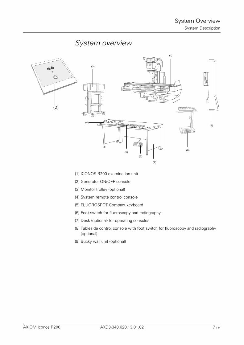
System overview
(1) ICONOS R200 examination unit
(2) Generator ON/OFF console
(3) Monitor trolley (optional)
(4) System remote control console
(5) FLUOROSPOT Compact keyboard
(6) Foot switch for fluoroscopy and radiography
(7) Desk (optional) for operating consoles
(8) Tableside control console with foot switch for fluoroscopy and radiography(optional)
(9) Bucky wall unit (optional)
(4)
(3)
(1)
(5)
(7)
(9)
(8)
(6)AX
IOM
(2)
AXIOM Iconos R200 AXD3-340.620.13.01.02 7 / 44
System OverviewSystem Description
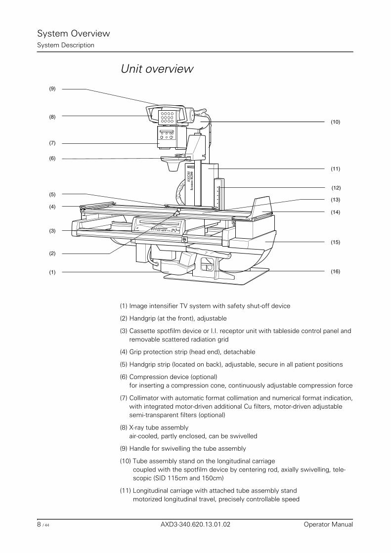
Unit overview
(1) Image intensifier TV system with safety shut-off device
(2) Handgrip (at the front), adjustable
(3) Cassette spotfilm device or I.I. receptor unit with tableside control panel and removable scattered radiation grid
(4) Grip protection strip (head end), detachable
(5) Handgrip strip (located on back), adjustable, secure in all patient positions
(6) Compression device (optional)for inserting a compression cone, continuously adjustable compression force
(7) Collimator with automatic format collimation and numerical format indication,with integrated motor-driven additional Cu filters, motor-driven adjustable semi-transparent filters (optional)
(8) X-ray tube assemblyair-cooled, partly enclosed, can be swivelled
(9) Handle for swivelling the tube assembly
(10) Tube assembly stand on the longitudinal carriagecoupled with the spotfilm device by centering rod, axially swivelling, tele-scopic (SID 115cm and 150cm)
(11) Longitudinal carriage with attached tube assembly standmotorized longitudinal travel, precisely controllable speed
(15)
(16)
(13)
(14)
(11)
(12)
(10)
(9)
(8)
(7)
(6)
(5)
(4)
(3)
(2)
(1)
AX
IOM
8 / 44 AXD3-340.620.13.01.02 Operator Manual
System OverviewSystem Description
(12) Tomographic height display (option) with laser line light localizer
(13) Tabletop with flat accessory railsmotor-driven longitudinal and transverse travel
(14) Footboardadjustable for use as seat,with attachment points for foot restraints,can be changed over from foot end to head end.
(15) Table framemotor-driven adjustable in height, can be tilted + 90°/-17°
(16) Unit base with tilting drive on installation plate
AXIOM Iconos R200 AXD3-340.620.13.01.02 9 / 44
System OverviewSystem Description
10 / 44 AXD3-340.620.13.01.02 Operator Manual
System Overview
Protective Measures
Emergency Procedures
Cleaning and disinfection
Warning
Due to the complexity of the system, the loss of X-ray imaging or other system functions during an examination or procedure can not be completely excluded.
Risk of failure during interventions
◆ Consider therefore the need to establish emergency procedures in such cas-es.
Caution
Use of harsh cleaning agents, liquids or sprays.
Risk of electrical hazard or damage to the system
◆ Use only substances for cleaning and disinfection, which are recommended.
◆ Do not let cleaning liquids seep into the openings of the system (e.g. air openings, gaps between covers).
◆ Observe the following cleaning and disinfection instructions.
AXIOM Iconos R200 AXD3-340.620.13.01.02 11 / 44
System OverviewProtective Measures
Radiation protection zones
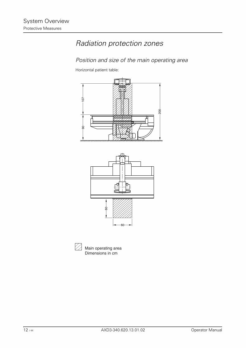
Position and size of the main operating area
Horizontal patient table:
Main operating areaDimensions in cm
x
60
60
107
90
200
12 / 44 AXD3-340.620.13.01.02 Operator Manual
System OverviewProtective Measures
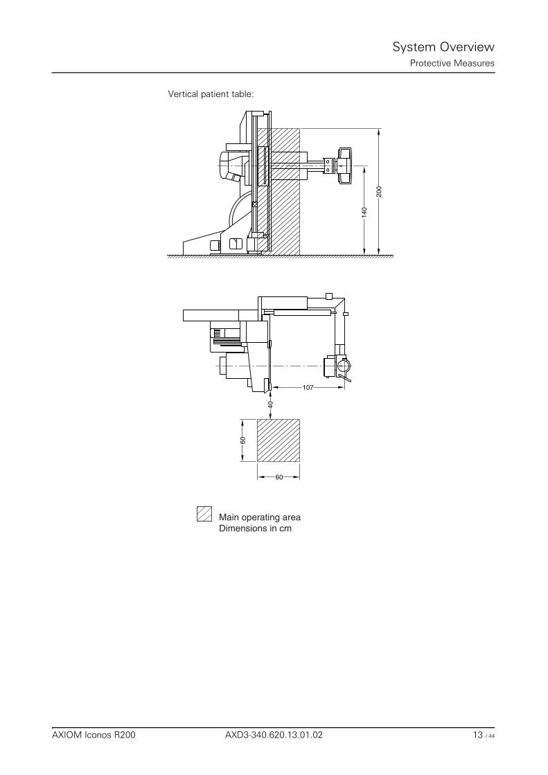
Vertical patient table:
Main operating areaDimensions in cm
xx
60
60
107
40
140
200
AXIOM Iconos R200 AXD3-340.620.13.01.02 13 / 44
System OverviewProtective Measures
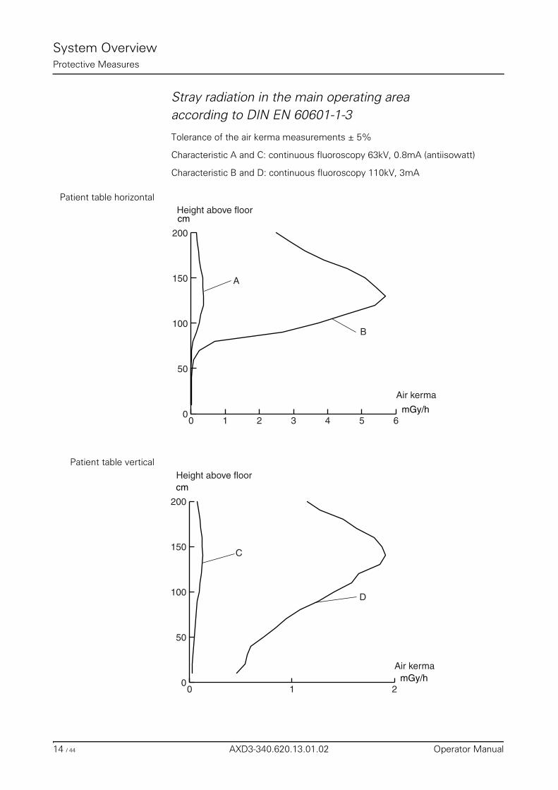
Stray radiation in the main operating areaaccording to DIN EN 60601-1-3
Tolerance of the air kerma measurements ± 5%
Characteristic A and C: continuous fluoroscopy 63kV, 0.8mA (antiisowatt)
Characteristic B and D: continuous fluoroscopy 110kV, 3mA
Patient table horizontal
Patient table vertical
0 1 2 3 4 5 60
50
100
150
200
cm
mGy/h
Height above floor
Air kerma
A
B
0 1 20
50
100
150
200
cm
mGy/h
Height above floor
Air kerma
C
D
14 / 44 AXD3-340.620.13.01.02 Operator Manual
System OverviewProtective Measures
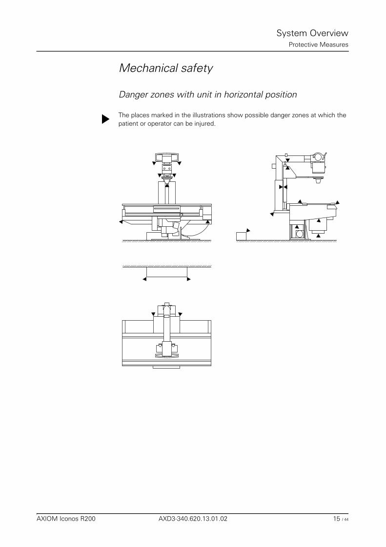
Mechanical safety
Danger zones with unit in horizontal position
The places marked in the illustrations show possible danger zones at which the patient or operator can be injured.
AXIOM Iconos R200 AXD3-340.620.13.01.02 15 / 44
System OverviewProtective Measures
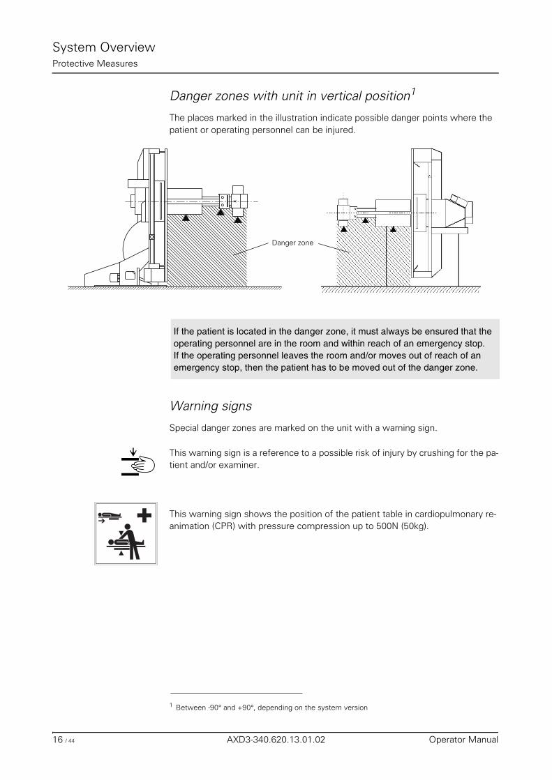
Danger zones with unit in vertical position1
The places marked in the illustration indicate possible danger points where the patient or operating personnel can be injured.
Warning signs
Special danger zones are marked on the unit with a warning sign.
This warning sign is a reference to a possible risk of injury by crushing for the pa-tient and/or examiner.
This warning sign shows the position of the patient table in cardiopulmonary re-animation (CPR) with pressure compression up to 500N (50kg).
1 Between -90° and +90°, depending on the system version
x
Danger zone
If the patient is located in the danger zone, it must always be ensured that the operating personnel are in the room and within reach of an emergency stop.If the operating personnel leaves the room and/or moves out of reach of an emergency stop, then the patient has to be moved out of the danger zone.
16 / 44 AXD3-340.620.13.01.02 Operator Manual
System OverviewProtective Measures
Grip locations
The following grip locations are provided:
❏ 1 handgrip (front)
❏ Grip protection strip (head end)
❏ Handgrip strip (back)
◆ Ensure that the handgrip strip, the grip protection strip and the handgrip are always attached.
If these grip locations cannot be used:
◆ Pay special attention to the stated possibilities of crushing between moving parts and their guide openings.
◆ Ensure during the examination that the patient under no circumstances holds on to the edges of the patient table.
Not intended as gripping point:
The handle for turning the tube assembly must not be used as grip location or hold for the patient.
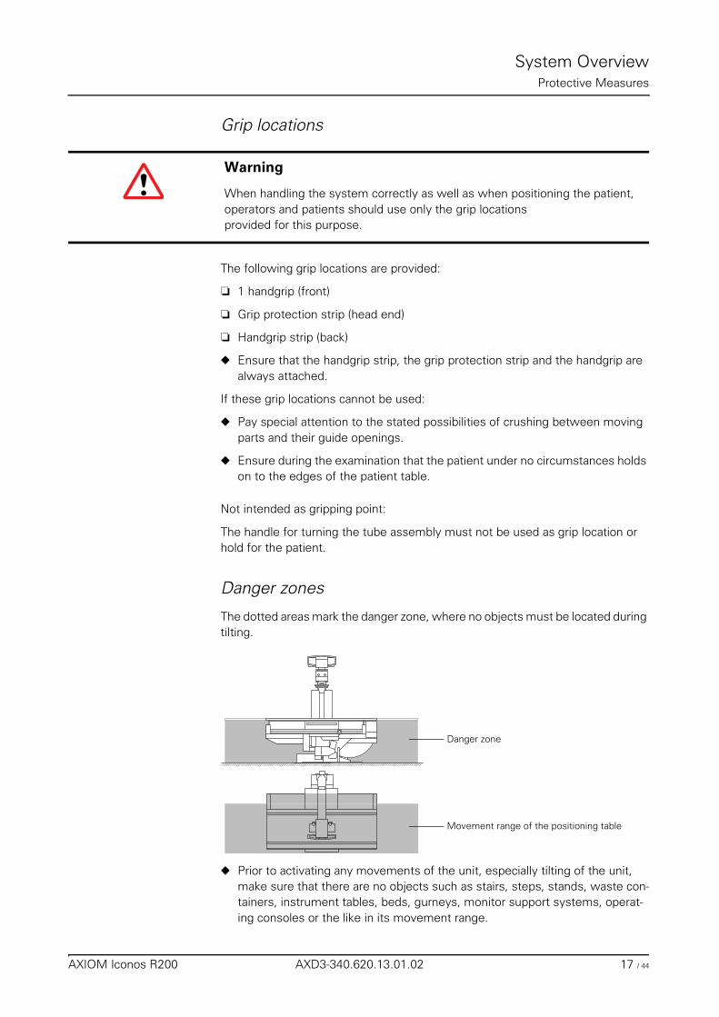
Danger zones
The dotted areas mark the danger zone, where no objects must be located during tilting.
◆ Prior to activating any movements of the unit, especially tilting of the unit, make sure that there are no objects such as stairs, steps, stands, waste con-tainers, instrument tables, beds, gurneys, monitor support systems, operat-ing consoles or the like in its movement range.
Warning
When handling the system correctly as well as when positioning the patient, operators and patients should use only the grip locations provided for this purpose.
Movement range of the positioning table
Danger zone
AXIOM Iconos R200 AXD3-340.620.13.01.02 17 / 44
System OverviewProtective Measures
These objects are not detected by the collision monitoring of the unit. Avoiding collisions of the unit with these objects is subject to the operator’s duty to take care.
If a collision of the unit with a rigid obstacle (e.g. step) has occurred,
◆ press one of the red emergency stop buttons,
◆ rescue the patient,
◆ immediately notify the SIEMENS Uptime Service.
❏ Avoid standing or sitting immediately adjacent to the system and especially do not sit next to the system with your legs or knees under the cross-beam at the head or foot end of the table.
❏ Take care that during system movements no one is in the area between the unit base and table.
❏ Take care that with the footboard attached there is a risk of collision with the extended cone (optional) when the tabletop and / or the longitudinal carriage are moving.
❏ Do not grasp in the loading shaft of the spotfilm device because of the risk of crushing.
Patient positioning
❏ All safety-related equipment must be installed and operable. In particular the handgrip strips (head end and lateral), handgrip, footboard, foot restraints, compression belt and shoulder supports.
❏ The patient’s hands, arms, legs, head and hair must not extend unsecured be-yond the edge of the tabletop.
❏ Observe the patient while moving the tabletop and in system movements and take care that any catheter is correctly located.
❏ In examinations with the table tilted up vertically, the footboard serves as an adjustable step or seat.– Ensure that the footboard is locked together with the tabletop on both
sides.– Check the firm location of the footboard.
Warning
Under no circumstances must the unit be tilted down further or tilted up, since externally invisible, but safety-relevant damage to the tilting drive may occur. Severe consequential damage including personal damage cannot be excluded in this case.
18 / 44 AXD3-340.620.13.01.02 Operator Manual
System OverviewProtective Measures
Patient positioning with unit in vertical position
During examinations with the unit in the upright position there is a risk of crush injuries to the patient if the X-ray system (stand with tube unit/receptor unit with image intensifier) is moved in the longitudinal direction.
◆ Position the X-ray system approximately in the acquisition position.
◆ Move the patient into the acquisition position.
◆ Set the X-ray system to object height. Always watch the patient when initiat-ing this movement.
Remote compression (optional)
❏ The motor-driven compression device requires special care on the part of the examiner for the applied compression forces, especially in the case of frail (e.g. infants), sick and elderly patients.
❏ Observe especially that both an increased risk of crushing for the patient with consequential injury and considerable mechanical shearing forces with risk of damage can occur between the compression cone and attached accessories, e.g. shoulder supports, lateral support (optional) or motor-driven infant cradle holder (optional) by collision during the motor-driven tabletop movement.
❏ When moving the compression carriage into the lowest position, the carriage may collide with the patient’s hand on the grip protection strip.– Use extreme caution when actuating the cone movement.
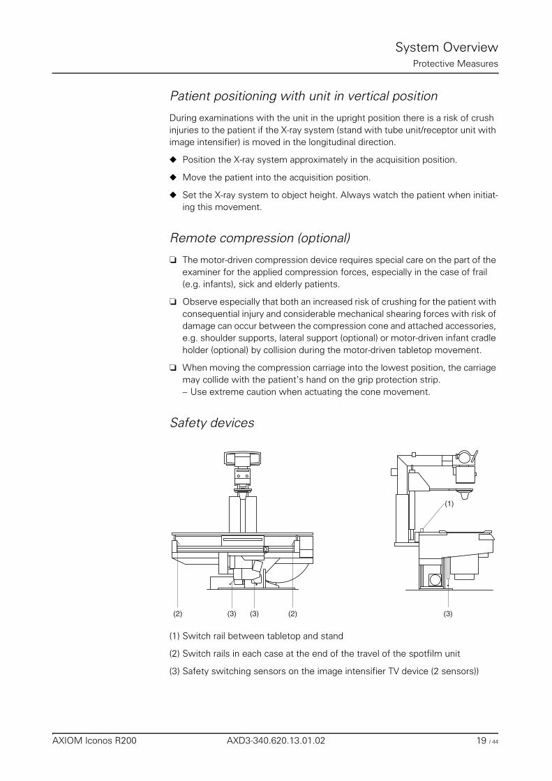
Safety devices
(1) Switch rail between tabletop and stand
(2) Switch rails in each case at the end of the travel of the spotfilm unit
(3) Safety switching sensors on the image intensifier TV device (2 sensors))
(1)
(2) (3)(3) (3)(2)
AXIOM Iconos R200 AXD3-340.620.13.01.02 19 / 44
System OverviewProtective Measures
On activation of one of the safety devices (shutdown devices) all system move-ments stop and are blocked.
This means that one cannot move out from the blockage oneself.
If it is not possible to remove the obstruction causing the problem, call in the Sie-mens Uptime Services.
Movements are possible again only after one of the safety devices has be deac-tivated.
Possible collisions of the system with a ceiling-mounted support1
❏ System movements are possible only if the ceiling-mounted support is in its park position or if the bypass switch is activated if necessary.
❏ Prior to actuating system movements with the bypass switch activated, verify that no collision can take place with the ceiling-mounted support, the X-ray tube assembly or the collimator. (No collision monitoring.)
Measures for avoiding equipment damage
◆ Before activating system movements, especially tilting the table, make sure that the movement range is free of obstructions.
◆ Move especially monitor support systems, operating consoles, gurneys, beds and instrument tables out from the tilting range of the table and remove chairs, steps, stands, waste containers and similar objects from the move-ment area. (No collision monitoring.)
◆ Do not place any objects or consumable material on the cover of the table sup-port, on the spotfilm device and on the longitudinal guides of the stand car-riage.– Considerable forces which can damage these objects in the area of move-
ment of the systems arise during movements of the spotfilm device or of the tabletop.
◆ Do not place any loose objects anywhere on the table.– These objects could fall down when the table is tilted, causing injury or
damage.
1 optional
Warning
If system movements are possible even though the ceiling-mounted support is not in the park position and the bypass switch is not activated, immediately press the emergency shutdown button and notify the SIEMENS Uptime Service.
20 / 44 AXD3-340.620.13.01.02 Operator Manual
System OverviewProtective Measures
◆ Do not stand at any place on the spotfilm device or on the covers of the table support outside the marked areas provided for this. – The covers can be deformed.
Components located underneath them are damaged and thus lead to oper-ating disturbances.
◆ Place no objects on the operating areas of the control consoles and the table-side control.
◆ In vertical table positions do not use the stand column, the tube assembly sup-port arm, the tube assembly cover or the primary collimator as seat or support.– This unallowed loading can lead to material breakage and damage to bear-
ings.
◆ Never put contrast medium cups or open containers with liquid or pasty con-tents on the unit, on the remote console or on the control cabinets.– Contrast medium can spill, leak or overflow into system parts and lead to
operational disturbances of the unit or to misinterpretation of exposures.
◆ When storing contrast medium in the cup holder on the compression carriage, use only cups with a maximum volume of 0.25 liter made of unbreakable ma-terials, i.e. under no circumstances glass or porcelain.– Remove contrast medium traces immediately!
Measures for avoiding unwanted radiation
◆ Before starting system movements make sure that the foot switch for fluo-roscopy and radiography (optional) in the examination room is not in the travel range of the image intensifier light distribution system.
Caution
Unintentional activation of control elements for movements
Collision with patient, operator or equipment
◆ Do not load the remote console with any objects, accessories, folders or documents.
To avoid unintentional activation of control elements for movements concerning bed exposure, please adhere to the following workflow:
◆ Select aquisition mode Bed exposure at the generator control console.
◆ Tilt the system and move it to the correct SID.
◆ Rotate the tube assembly accordingly.
◆ Position the patient.
◆ Control patient and system.
◆ Don’t let patient stay in system area during absence of operator.
AXIOM Iconos R200 AXD3-340.620.13.01.02 21 / 44
System OverviewProtective Measures
Safety-relevant parts subject to wearThis system contains no safety-relevant parts subject to wear.
Maintenance intervalsMaintenance must be performed annually in order to ensure the safety and func-tioning ability of the system.If you have not concluded a maintenance contract, please notify the Siemens Up-time Service on time.
CAREWATCH
Display data
At the start of fluoroscopy/acquisition the following system parameters are dis-played in the lower right area of the live monitor:
1st line– Display of the prefilter in fluoroscopy
2nd line– Display of the prefilter in radiography
With the area dose product meter (optional)1
3rd line – Area dose product in cGycm²
4th line
During fluoroscopy
– Display of the patient entrance dose2 in mGy/min
In the radiation pauses– the percentage of the patient entrance dose reached related to a config-
urable limit1 of 0.5 to 5 Gy or– the accumulated patient entrance dose in mGy is displayed.
1 can be configured by the SIEMENS Uptime Service2 standardized to 30 cm above the tabletop
The measuring device must be calibrated at regular intervals. This is done within the scope of a maintenance contract. If no maintenance contract have been con-cluded, the measuring device can be calibrated by the Siemens Uptime Service of the manufacturer.
22 / 44 AXD3-340.620.13.01.02 Operator Manual
System OverviewProtective Measures
Resetting the area dose product
Once the examination is finished,
◆ actuate the reset button at the integrated generator control console – The displays for the area dose product and the patient entrance dose are
reset to zero.
➩ Refer to the Operator Manual of Fluorospot Compact.
AXIOM Iconos R200 AXD3-340.620.13.01.02 23 / 44

System OverviewProtective Measures
24 / 44 AXD3-340.620.13.01.02 Operator Manual
System Overview
Operating and Display Elements
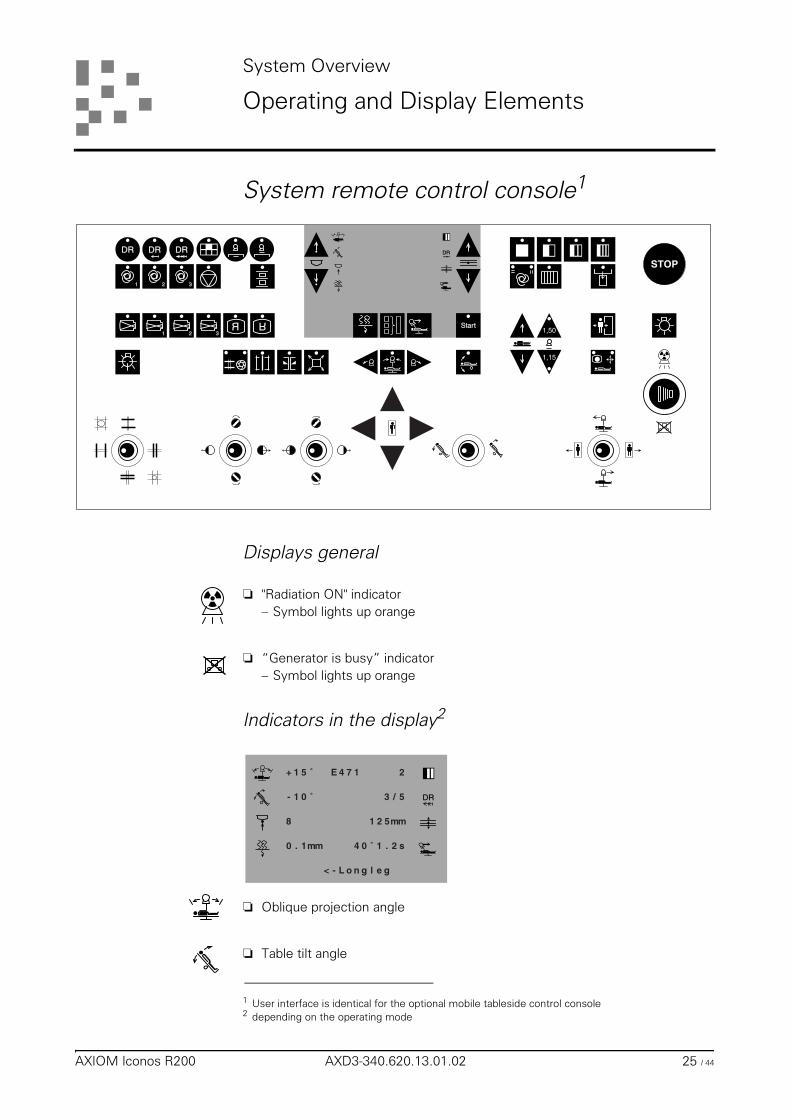
System remote control console1
Displays general
❏ "Radiation ON" indicator– Symbol lights up orange
❏ “Generator is busy” indicator– Symbol lights up orange
Indicators in the display2
❏ Oblique projection angle
❏ Table tilt angle
1 User interface is identical for the optional mobile tableside control console
Start
DR
1 2 3
1 2 3R
R1,50
1,15
STOPDR DR DR
2 depending on the operating mode
DR
+ 1 5 ˚
- 1 0 ˚
8
0 . 1mm
2
5/3
mm521
s2.1˚04
E 4 7 1
L o gelgn-<
AXIOM Iconos R200 AXD3-340.620.13.01.02 25 / 44
System OverviewOperating and Display Elements
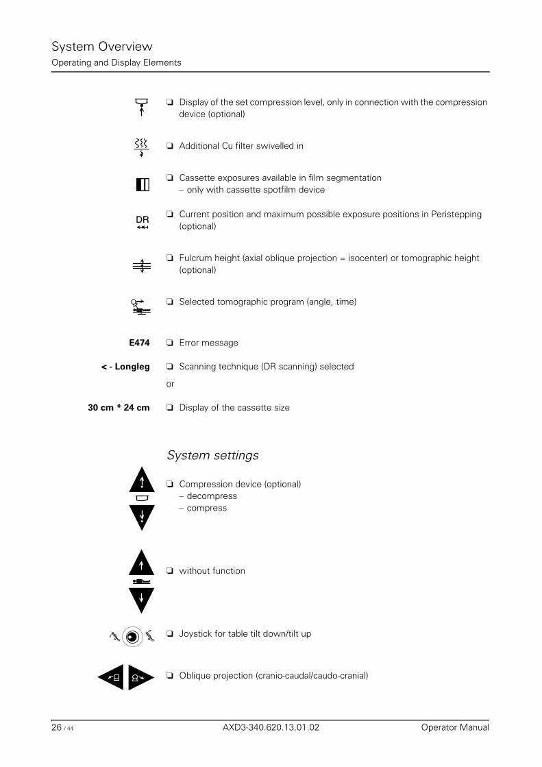
❏ Display of the set compression level, only in connection with the compression device (optional)
❏ Additional Cu filter swivelled in
❏ Cassette exposures available in film segmentation– only with cassette spotfilm device
❏ Current position and maximum possible exposure positions in Peristepping (optional)
❏ Fulcrum height (axial oblique projection = isocenter) or tomographic height (optional)
❏ Selected tomographic program (angle, time)
E474 ❏ Error message
< - Longleg ❏ Scanning technique (DR scanning) selected
or
30 cm * 24 cm ❏ Display of the cassette size
System settings
❏ Compression device (optional)– decompress– compress
❏ without function
❏ Joystick for table tilt down/tilt up
❏ Oblique projection (cranio-caudal/caudo-cranial)
DRDR
26 / 44 AXD3-340.620.13.01.02 Operator Manual
System OverviewOperating and Display Elements
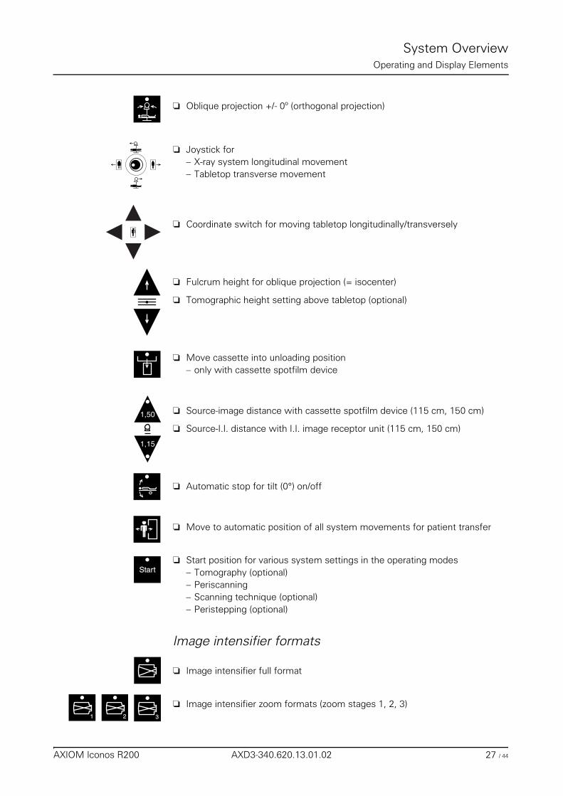
❏ Oblique projection +/- 0º (orthogonal projection)
❏ Joystick for– X-ray system longitudinal movement– Tabletop transverse movement
❏ Coordinate switch for moving tabletop longitudinally/transversely
❏ Fulcrum height for oblique projection (= isocenter)
❏ Tomographic height setting above tabletop (optional)
❏ Move cassette into unloading position– only with cassette spotfilm device
❏ Source-image distance with cassette spotfilm device (115 cm, 150 cm)
❏ Source-I.I. distance with I.I. image receptor unit (115 cm, 150 cm)
❏ Automatic stop for tilt (0°) on/off
❏ Move to automatic position of all system movements for patient transfer
❏ Start position for various system settings in the operating modes– Tomography (optional)– Periscanning– Scanning technique (optional)– Peristepping (optional)
Image intensifier formats
❏ Image intensifier full format
❏ Image intensifier zoom formats (zoom stages 1, 2, 3)
1,50
1,15
StarStartt
1 32
AXIOM Iconos R200 AXD3-340.620.13.01.02 27 / 44
System OverviewOperating and Display Elements
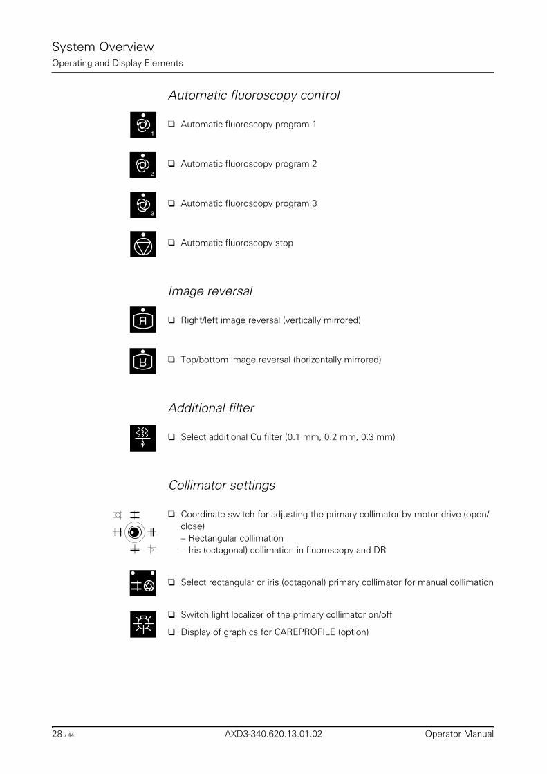
Automatic fluoroscopy control
❏ Automatic fluoroscopy program 1
❏ Automatic fluoroscopy program 2
❏ Automatic fluoroscopy program 3
❏ Automatic fluoroscopy stop
Image reversal
❏ Right/left image reversal (vertically mirrored)
❏ Top/bottom image reversal (horizontally mirrored)
Additional filter
❏ Select additional Cu filter (0.1 mm, 0.2 mm, 0.3 mm)
Collimator settings
❏ Coordinate switch for adjusting the primary collimator by motor drive (open/close)– Rectangular collimation– Iris (octagonal) collimation in fluoroscopy and DR
❏ Select rectangular or iris (octagonal) primary collimator for manual collimation
❏ Switch light localizer of the primary collimator on/off
❏ Display of graphics for CAREPROFILE (option)
1
2
3
R
R
28 / 44 AXD3-340.620.13.01.02 Operator Manual
System OverviewOperating and Display Elements
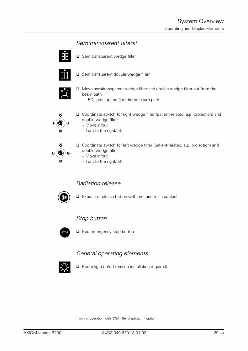
Semitransparent filters1
❏ Semitransparent wedge filter
❏ Semitransparent double wedge filter
❏ Move semitransparent wedge filter and double wedge filter out from the beam path– LED lights up: no filter in the beam path
❏ Coordinate switch for right wedge filter (patient-related, a.p. projection) and double wedge filter– Move in/out– Turn to the right/left
❏ Coordinate switch for left wedge filter (patient-related, a.p. projection) and double wedge filter– Move in/out– Turn to the right/left
Radiation release
❏ Exposure release button with pre- and main contact
Stop button
❏ Red emergency stop button
General operating elements
❏ Room light on/off (on-site installation required)
1 only in operation with "DSA filter diaphragm” option
STOP
AXIOM Iconos R200 AXD3-340.620.13.01.02 29 / 44
System OverviewOperating and Display Elements
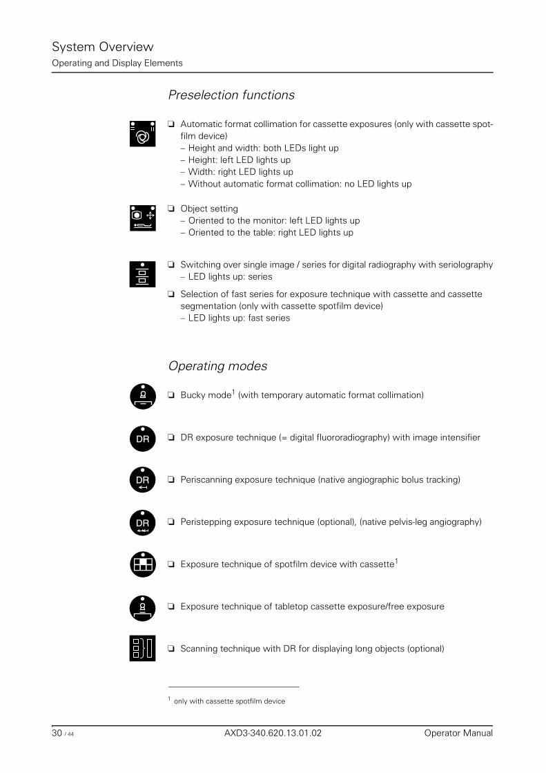
Preselection functions
❏ Automatic format collimation for cassette exposures (only with cassette spot-film device)– Height and width: both LEDs light up– Height: left LED lights up– Width: right LED lights up– Without automatic format collimation: no LED lights up
❏ Object setting – Oriented to the monitor: left LED lights up– Oriented to the table: right LED lights up
❏ Switching over single image / series for digital radiography with seriolography– LED lights up: series
❏ Selection of fast series for exposure technique with cassette and cassette segmentation (only with cassette spotfilm device)– LED lights up: fast series
Operating modes
❏ Bucky mode1 (with temporary automatic format collimation)
❏ DR exposure technique (= digital fluororadiography) with image intensifier
❏ Periscanning exposure technique (native angiographic bolus tracking)
❏ Peristepping exposure technique (optional), (native pelvis-leg angiography)
❏ Exposure technique of spotfilm device with cassette1
❏ Exposure technique of tabletop cassette exposure/free exposure
❏ Scanning technique with DR for displaying long objects (optional)
1 only with cassette spotfilm device
DRDR
DRDR
DRDR
30 / 44 AXD3-340.620.13.01.02 Operator Manual
System OverviewOperating and Display Elements
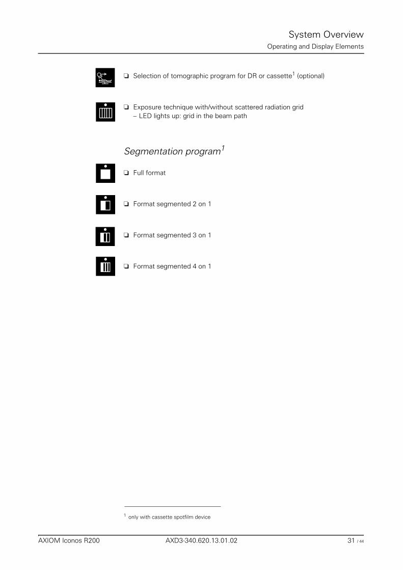
❏ Selection of tomographic program for DR or cassette1 (optional)
❏ Exposure technique with/without scattered radiation grid– LED lights up: grid in the beam path
Segmentation program1
❏ Full format
❏ Format segmented 2 on 1
❏ Format segmented 3 on 1
❏ Format segmented 4 on 1
1 only with cassette spotfilm device
AXIOM Iconos R200 AXD3-340.620.13.01.02 31 / 44
System OverviewOperating and Display Elements
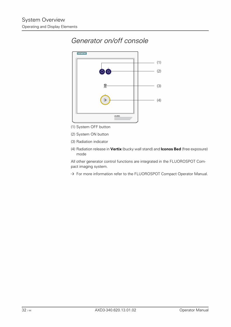
Generator on/off console
(1) System OFF button
(2) System ON button
(3) Radiation indicator
(4) Radiation release in Vertix (bucky wall stand) and Iconos Bed (free exposure) mode
All other generator control functions are integrated in the FLUOROSPOT Com-pact imaging system.
➩ For more information refer to the FLUOROSPOT Compact Operator Manual.
(1)
(2)
(3)
(4)
32 / 44 AXD3-340.620.13.01.02 Operator Manual
System OverviewOperating and Display Elements
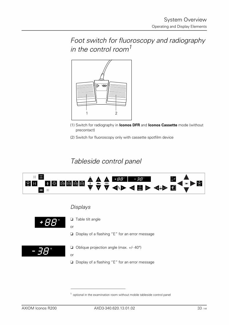
Foot switch for fluoroscopy and radiography in the control room1
(1) Switch for radiography in Iconos DFR and Iconos Cassette mode (without precontact)
(2) Switch for fluoroscopy only with cassette spotfilm device
Tableside control panel
Displays
❏ Table tilt angle
or
❏ Display of a flashing “E” for an error message
❏ Oblique projection angle (max. +/- 40°)
or
❏ Display of a flashing “E” for an error message
1 optional in the examination room without mobile tableside control panel
1 2
1 2 3
1,50
1,15
P˚ ˚
˚
˚
AXIOM Iconos R200 AXD3-340.620.13.01.02 33 / 44
System OverviewOperating and Display Elements
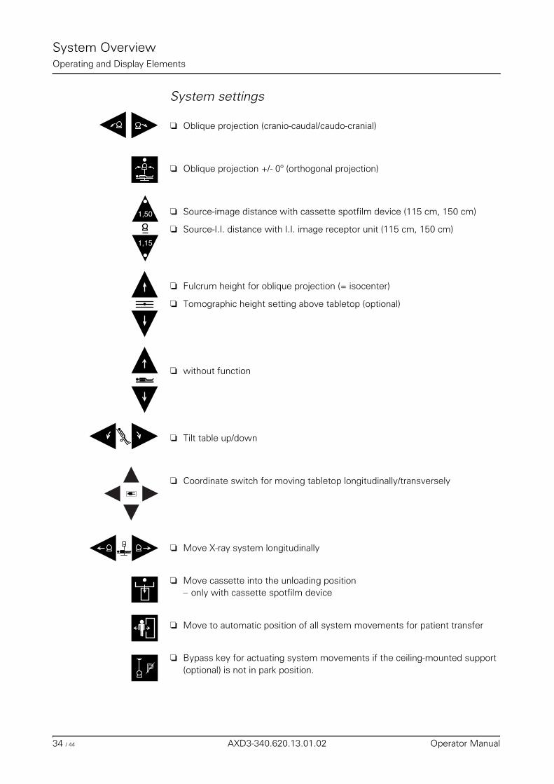
System settings
❏ Oblique projection (cranio-caudal/caudo-cranial)
❏ Oblique projection +/- 0º (orthogonal projection)
❏ Source-image distance with cassette spotfilm device (115 cm, 150 cm)
❏ Source-I.I. distance with I.I. image receptor unit (115 cm, 150 cm)
❏ Fulcrum height for oblique projection (= isocenter)
❏ Tomographic height setting above tabletop (optional)
❏ without function
❏ Tilt table up/down
❏ Coordinate switch for moving tabletop longitudinally/transversely
❏ Move X-ray system longitudinally
❏ Move cassette into the unloading position– only with cassette spotfilm device
❏ Move to automatic position of all system movements for patient transfer
❏ Bypass key for actuating system movements if the ceiling-mounted support (optional) is not in park position.
1,50
1,15
P
34 / 44 AXD3-340.620.13.01.02 Operator Manual
System OverviewOperating and Display Elements
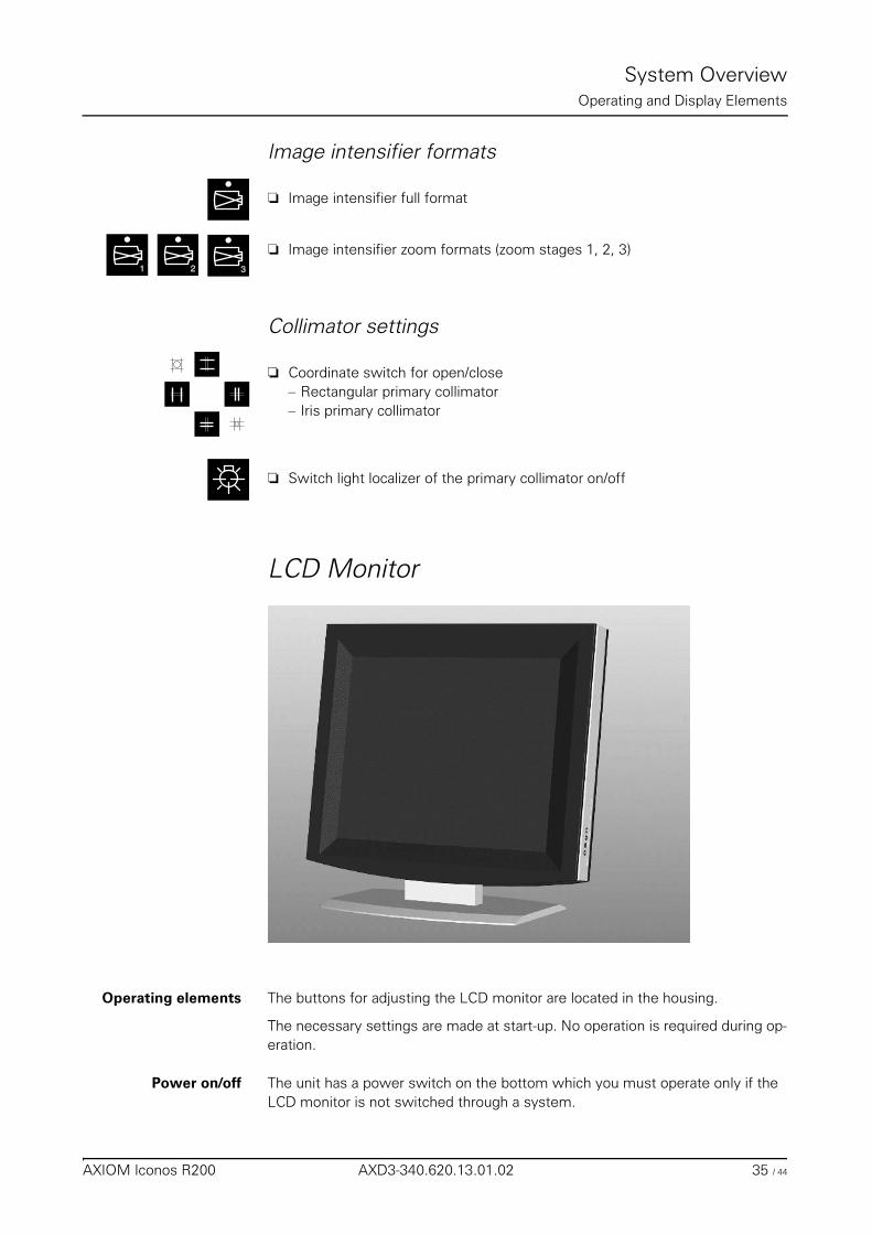
Image intensifier formats
❏ Image intensifier full format
❏ Image intensifier zoom formats (zoom stages 1, 2, 3)
Collimator settings
❏ Coordinate switch for open/close– Rectangular primary collimator– Iris primary collimator
❏ Switch light localizer of the primary collimator on/off
LCD Monitor
Operating elements The buttons for adjusting the LCD monitor are located in the housing.
The necessary settings are made at start-up. No operation is required during op-eration.
Power on/off The unit has a power switch on the bottom which you must operate only if the LCD monitor is not switched through a system.
1 32
AXIOM Iconos R200 AXD3-340.620.13.01.02 35 / 44
System OverviewOperating and Display Elements
Operating indicator The unit has a green LED operating indicator on the right side above the adjusting elements.
Errors ❏ If the LCD monitor displays no image or a blurred image, vertical lines or other defects, please contact the SIEMENS Service.
❏ If no input signal is present, the ’No Signal’ message appears.
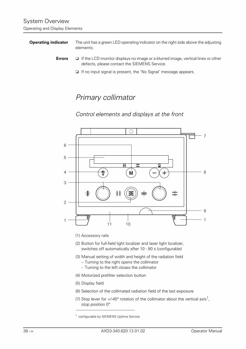
Primary collimator
Control elements and displays at the front
(1) Accessory rails
(2) Button for full-field light localizer and laser light localizer, switches off automatically after 10 - 90 s (configurable)
(3) Manual setting of width and height of the radiation field– Turning to the right opens the collimator– Turning to the left closes the collimator
(4) Motorized prefilter selection button
(5) Display field
(6) Selection of the collimated radiation field of the last exposure
(7) Stop lever for +/-45° rotation of the collimator about the vertical axis1, stop position 0°
M
1
3
8
9
1
6
5
4
7
2
1011
1 configurable by SIEMENS Uptime Service
36 / 44 AXD3-340.620.13.01.02 Operator Manual
System OverviewOperating and Display Elements
(8) Buttons for entering the SID for free setting
(9) Tape measure for SID setting (cm and inch)
(10) Slide for covering the laser line light localizer
(11) Integrated measuring chamber for dose area product (optional)
(12) Manual prefilter levers at the left side (not shown )
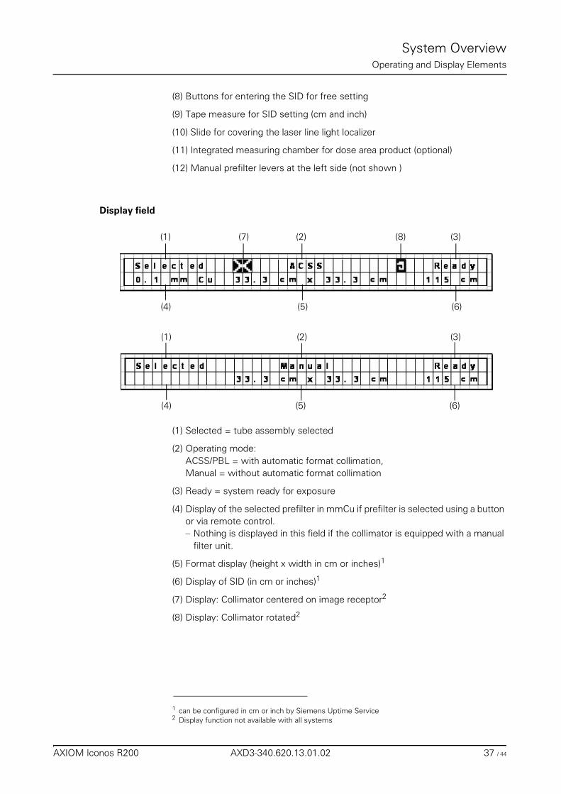
Display field
(1) Selected = tube assembly selected
(2) Operating mode: ACSS/PBL = with automatic format collimation,Manual = without automatic format collimation
(3) Ready = system ready for exposure
(4) Display of the selected prefilter in mmCu if prefilter is selected using a button or via remote control.– Nothing is displayed in this field if the collimator is equipped with a manual
filter unit.
(5) Format display (height x width in cm or inches)1
(6) Display of SID (in cm or inches)1
(7) Display: Collimator centered on image receptor2
(8) Display: Collimator rotated2
(1)
(1)
(4)
(4)
(7) (2) (8) (3)
(5) (6)
(2) (3)
(5) (6)
1 can be configured in cm or inch by Siemens Uptime Service2 Display function not available with all systems
AXIOM Iconos R200 AXD3-340.620.13.01.02 37 / 44
System OverviewOperating and Display Elements
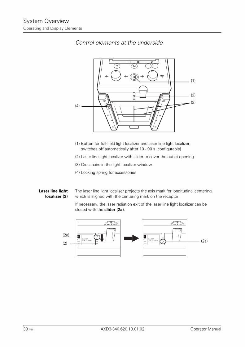
Control elements at the underside
(1) Button for full-field light localizer and laser line light localizer, switches off automatically after 10 - 90 s (configurable)
(2) Laser line light localizer with slider to cover the outlet opening
(3) Crosshairs in the light localizer window
(4) Locking spring for accessories
Laser line lightlocalizer (2)
The laser line light localizer projects the axis mark for longitudinal centering, which is aligned with the centering mark on the receptor.
If necessary, the laser radiation exit of the laser line light localizer can be closed with the slider (2a).
M
(1)
(2)
(3)(4)
(2)
(2a)
(2a)
38 / 44 AXD3-340.620.13.01.02 Operator Manual
System OverviewOperating and Display Elements
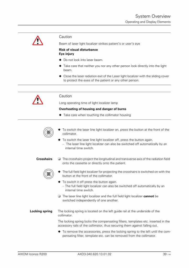
◆ To switch the laser line light localizer on, press the button at the front of the collimator.
◆ To switch the laser line light localizer off, press the button again.– The laser line light localizer can also be switched off automatically by an
internal time switch.
Crosshairs ❏ The crosshairs project the longitudinal and transverse axis of the radiation field onto the cassette or directly onto the patient.
◆ The full field light localizer for projecting the crosshairs is switched on with the button at the front of the collimator.
◆ To switch it off press the button again.– The full field light localizer can also be switched off automatically by an
internal time switch.
❏ The laser line light localizer and the full field light localizer cannot be switched independently of one another.
Locking spring The locking spring is located on the left guide rail at the underside of the collimator.
The locking spring locks the compensating filters, templates etc. inserted in the accessory rails of the collimator, thus securing them against falling out.
◆ To remove the accessories, press the locking spring to the left until the com-pensating filter, template etc. can be removed from the collimator.
Caution
Beam of laser light localizer strikes patient’s or user’s eye
Risk of visual disturbanceEye injury
◆ Do not look into laser beam.
◆ Take care that neither you nor any other person look directly into the light beam.
◆ Close the laser radiation exit of the Laser light localizer with the sliding cover to protect the eyes of the patient or any other person.
Caution
Long operating time of light localizer lamp
Overheating of housing and danger of burns
◆ Take care when touching the collimator housing
AXIOM Iconos R200 AXD3-340.620.13.01.02 39 / 44
System OverviewOperating and Display Elements
Prefilter selection
Motorized prefilter selection1
◆ To select a prefilter press the prefilter selection button.– The Cu prefilter changes to the next value each time the button is pressed– Possible settings are:
0.0 mm Cu (no) prefilter0.1 mm Cu prefilter0.2 mm Cu prefilter0.3 mm Cu prefilter
– The currently selected prefilter is shown in the display.
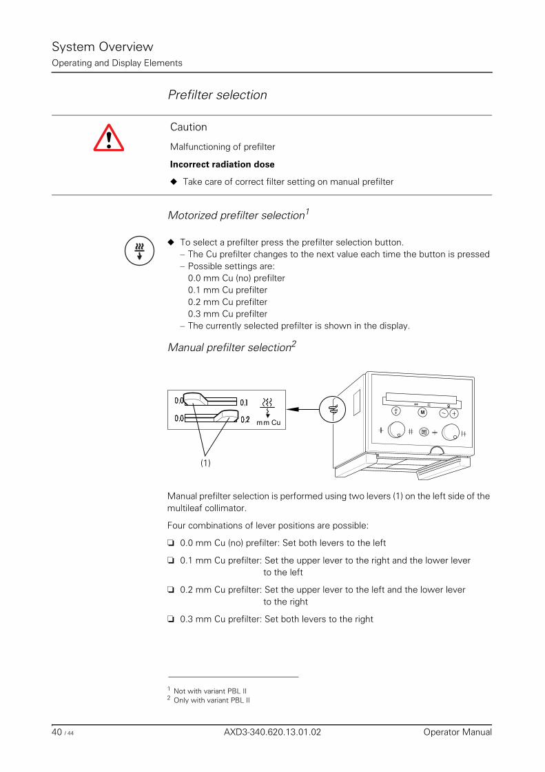
Manual prefilter selection2
Manual prefilter selection is performed using two levers (1) on the left side of the multileaf collimator.
Four combinations of lever positions are possible:
❏ 0.0 mm Cu (no) prefilter: Set both levers to the left
❏ 0.1 mm Cu prefilter: Set the upper lever to the right and the lower lever to the left
❏ 0.2 mm Cu prefilter: Set the upper lever to the left and the lower leverto the right
❏ 0.3 mm Cu prefilter: Set both levers to the right
Caution
Malfunctioning of prefilter
Incorrect radiation dose
◆ Take care of correct filter setting on manual prefilter
1 Not with variant PBL II2 Only with variant PBL II
(1)
40 / 44 AXD3-340.620.13.01.02 Operator Manual
System OverviewOperating and Display Elements
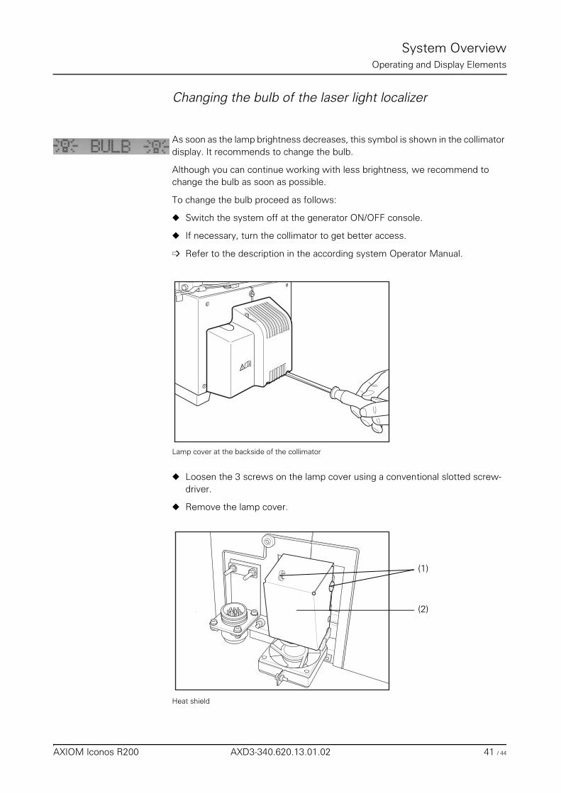
Changing the bulb of the laser light localizer
As soon as the lamp brightness decreases, this symbol is shown in the collimator display. It recommends to change the bulb.
Although you can continue working with less brightness, we recommend to change the bulb as soon as possible.
To change the bulb proceed as follows:
◆ Switch the system off at the generator ON/OFF console.
◆ If necessary, turn the collimator to get better access.
➩ Refer to the description in the according system Operator Manual.
Lamp cover at the backside of the collimator
◆ Loosen the 3 screws on the lamp cover using a conventional slotted screw-driver.
◆ Remove the lamp cover.
Heat shield
(1)
(2)
AXIOM Iconos R200 AXD3-340.620.13.01.02 41 / 44
System OverviewOperating and Display Elements
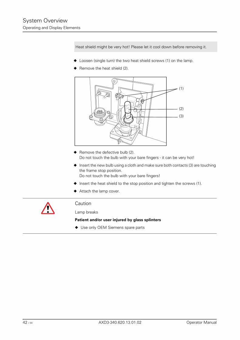
◆ Loosen (single turn) the two heat shield screws (1) on the lamp.
◆ Remove the heat shield (2).
◆ Remove the defective bulb (2). Do not touch the bulb with your bare fingers - it can be very hot!
◆ Insert the new bulb using a cloth and make sure both contacts (3) are touching the frame stop position.Do not touch the bulb with your bare fingers!
◆ Insert the heat shield to the stop position and tighten the screws (1).
◆ Attach the lamp cover.
Heat shield might be very hot! Please let it cool down before removing it.
(1)
(2)
(3)
Caution
Lamp breaks
Patient and/or user injured by glass splinters
◆ Use only OEM Siemens spare parts
42 / 44 AXD3-340.620.13.01.02 Operator Manual
System OverviewOperating and Display Elements
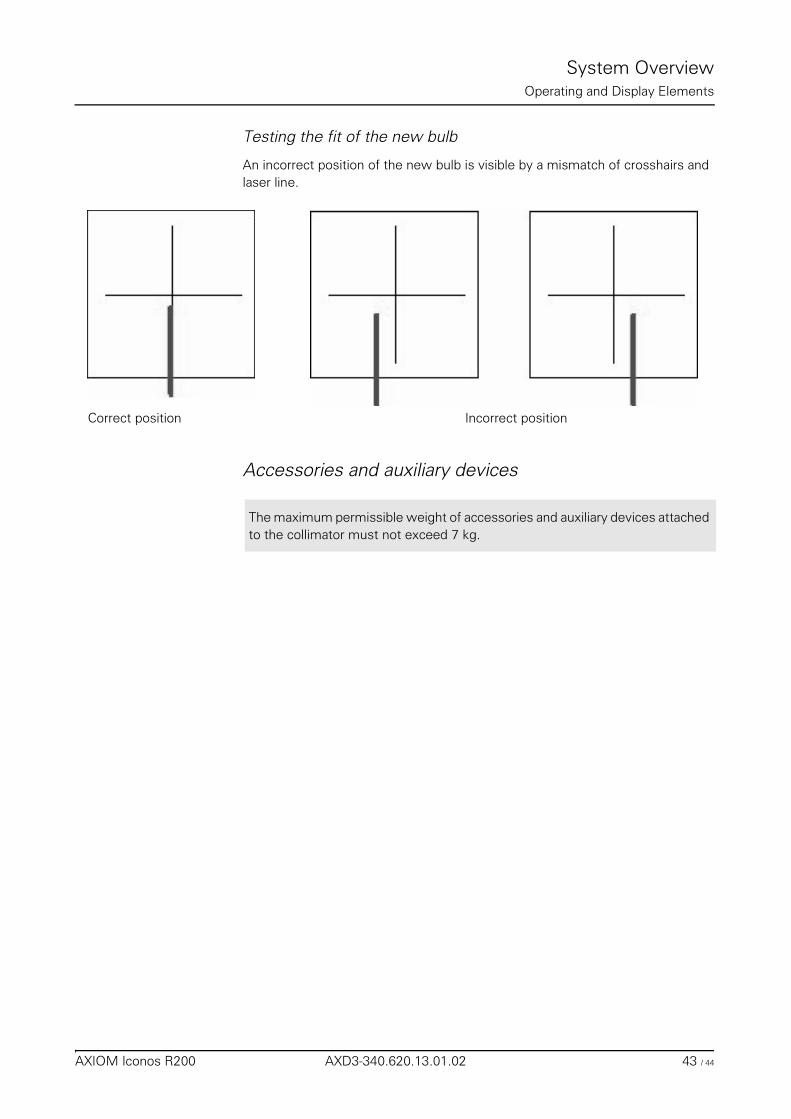
Testing the fit of the new bulb
An incorrect position of the new bulb is visible by a mismatch of crosshairs and laser line.
Accessories and auxiliary devices
Correct position Incorrect position
The maximum permissible weight of accessories and auxiliary devices attached to the collimator must not exceed 7 kg.
AXIOM Iconos R200 AXD3-340.620.13.01.02 43 / 44
System OverviewOperating and Display Elements
44 / 44 AXD3-340.620.13.01.02 Operator Manual
System OperationTable of Contents
Operator Manual
System Operation
Chapter: On-Off/Emergency Stop
Switching the system on .................................................................................................... 5
Switching the system off ................................................................................................... 6
Emergency SHUTDOWN button (installed on-site) ............................................................ 6
Standby power supply ........................................................................................................ 6Standby power supply inside the hospital ............................................................................ 6Battery-supported standby power supply (optional) ................................................................ 6
Red Emergency STOP button ............................................................................................ 7
Patient rescue ..................................................................................................................... 8
Chapter: Functional and Safety Check
Daily tests ........................................................................................................................... 9After switching the system on ........................................................................................... 9
Prior to the examination ........................................................................................... 9During the examination .................................................................................................. 10
Monthly tests ................................................................................................................... 10
Legally required tests ....................................................................................................... 10
Chapter: System Settings
General notes ................................................................................................................... 11Collision protection / Safety areas ..................................................................................... 11Operating elements for system positions ........................................................................... 11Object-dependent system settings ................................................................................... 12Start positions .............................................................................................................. 12General notes on error messages ..................................................................................... 12Behavior of the system settings in the case of a fault ........................................................... 13
AXIOM Iconos R200 AXD3-340.620.13.01.02 1 / 32
System OperationTable of Contents
Moving the X-ray system longitudinally ............................................................................ 14
Tabletop ............................................................................................................................ 15Moving the tabletop longitudinally/transversely ................................................................... 15Lowering the tabletop completely with the table vertical ....................................................... 16
Tube assembly stand ....................................................................................................... 17Setting the projection angle (oblique projection) .................................................................. 17Setting orthogonal projection (oblique projection +/- 0°) ........................................................ 18Reading off the projection angle ....................................................................................... 18
Tabletop ............................................................................................................................ 180° position of the table ................................................................................................... 19Tilting the table up/down ................................................................................................ 19Reading the table tilt ...................................................................................................... 20
Compression device (optional) ......................................................................................... 21Using the compression device ......................................................................................... 21Reading the compression level ........................................................................................ 22
Tomographic equipment (optional) ................................................................................... 22Setting the fulcrum height .............................................................................................. 22Switching on the fulcrum height light localizer ..................................................................... 23Reading the fulcrum height ............................................................................................. 23
Manual tube assembly rotation ........................................................................................ 24
Moving the grid into / out of the beam path ..................................................................... 24
Setting the source-image distance ................................................................................... 25
Chapter: Setting the Image Geometry
Limiting the radiation field (collimation) ............................................................................ 27Rectangular and /or iris collimation .................................................................................... 27
Selection / deselection .......................................................................................... 27Setting ............................................................................................................... 28
Semitransparent wedge filters (optional) ............................................................................ 28Selection / deselection .......................................................................................... 28Moving the semitransparent wedge filters ................................................................. 29
CAREPROFILE, collimation without radiation (optional) ......................................................... 29
CAREPOSITION (optional) ................................................................................................ 29
Additional Cu filter ............................................................................................................ 30
2 / 32 AXD3-340.620.13.01.02 Operator Manual
System OperationTable of Contents
Image reversal .................................................................................................................. 30
Switching over the image intensifier format ..................................................................... 31
AXIOM Iconos R200 AXD3-340.620.13.01.02 3 / 32
System OperationTable of Contents
4 / 32 AXD3-340.620.13.01.02 Operator Manual
System Operation
On-Off/Emergency Stop
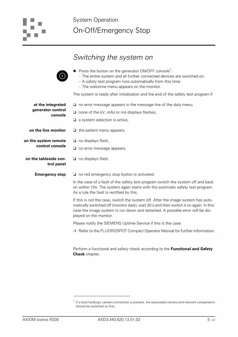
Switching the system on
◆ Press the button on the generator ON/OFF console1.– The entire system and all further connected devices are switched on.– A safety test program runs automatically from this time.– The welcome menu appears on the monitor.
The system is ready after initialization and the end of the safety test program if
at the integratedgenerator control
console
❏ no error message appears in the message line of the data menu,
❏ none of the kV, mAs or ms displays flashes,
❏ a system selection is active,
on the live monitor ❏ the patient menu appears,
on the system remotecontrol console
❏ no displays flash,
❏ no error message appears,
on the tableside con-trol panel
❏ no displays flash,
Emergency stop ❏ no red emergency stop button is activated.
In the case of a fault of the safety test program switch the system off and back on within 10s. The system again starts with the automatic safety test program. As a rule the fault is rectified by this.
If this is not the case, switch the system off. After the image system has auto-matically switched off (monitor dark), wait 30 s and then switch it on again. In this case the image system is run down and restarted. A possible error will be dis-played on the monitor.
Please notify the SIEMENS Uptime Service if this is the case.
➩ Refer to the FLUOROSPOT Compact Operator Manual for further information.
Perform a functional and safety check according to the Functional and Safety Check chapter.
1 If a local hardcopy camera connection is present, the associated camera and network componentsshould be switched on first.
AXIOM Iconos R200 AXD3-340.620.13.01.02 5 / 32
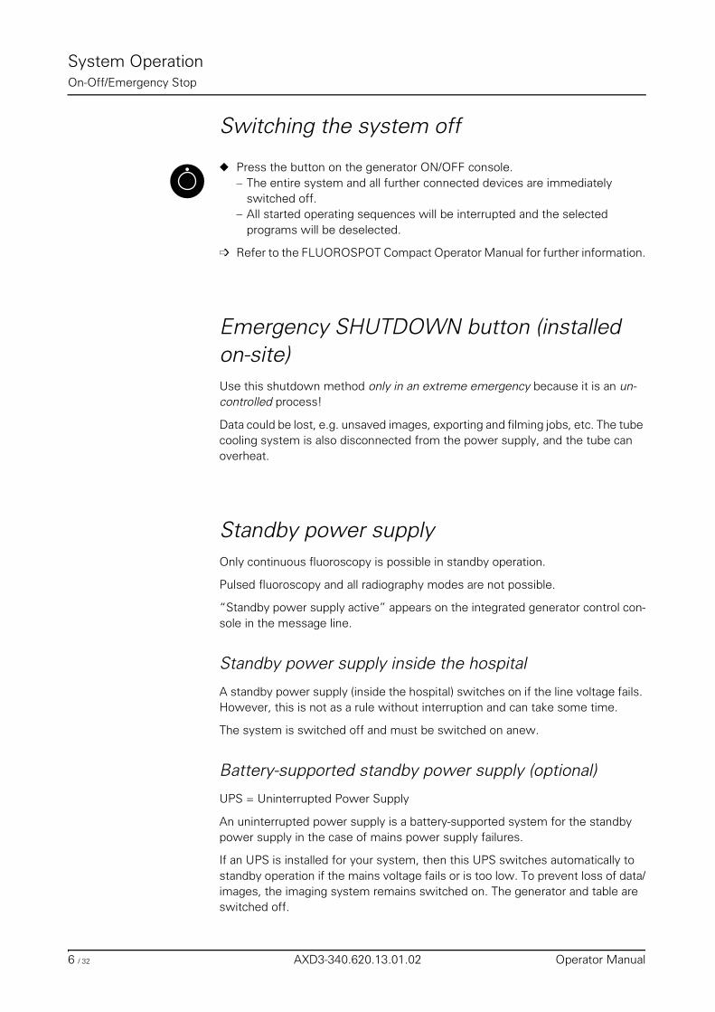
System OperationOn-Off/Emergency Stop
Switching the system off
◆ Press the button on the generator ON/OFF console.– The entire system and all further connected devices are immediately
switched off.– All started operating sequences will be interrupted and the selected
programs will be deselected.
➩ Refer to the FLUOROSPOT Compact Operator Manual for further information.
Emergency SHUTDOWN button (installed on-site)Use this shutdown method only in an extreme emergency because it is an un-controlled process!
Data could be lost, e.g. unsaved images, exporting and filming jobs, etc. The tube cooling system is also disconnected from the power supply, and the tube can overheat.
Standby power supplyOnly continuous fluoroscopy is possible in standby operation.
Pulsed fluoroscopy and all radiography modes are not possible.
“Standby power supply active” appears on the integrated generator control con-sole in the message line.
Standby power supply inside the hospital
A standby power supply (inside the hospital) switches on if the line voltage fails. However, this is not as a rule without interruption and can take some time.
The system is switched off and must be switched on anew.
Battery-supported standby power supply (optional)
UPS = Uninterrupted Power Supply
An uninterrupted power supply is a battery-supported system for the standby power supply in the case of mains power supply failures.
If an UPS is installed for your system, then this UPS switches automatically to standby operation if the mains voltage fails or is too low. To prevent loss of data/images, the imaging system remains switched on. The generator and table are switched off.
6 / 32 AXD3-340.620.13.01.02 Operator Manual
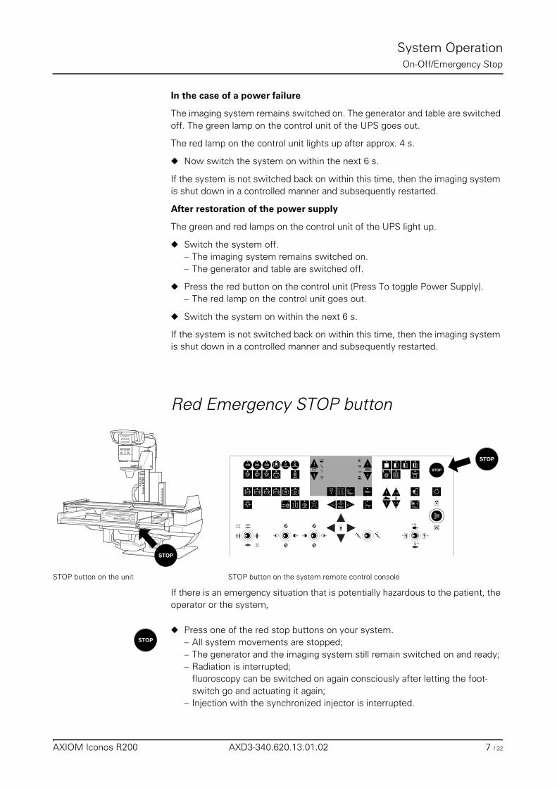
System OperationOn-Off/Emergency Stop
In the case of a power failure
The imaging system remains switched on. The generator and table are switched off. The green lamp on the control unit of the UPS goes out.
The red lamp on the control unit lights up after approx. 4 s.
◆ Now switch the system on within the next 6 s.
If the system is not switched back on within this time, then the imaging system is shut down in a controlled manner and subsequently restarted.
After restoration of the power supply
The green and red lamps on the control unit of the UPS light up.
◆ Switch the system off.– The imaging system remains switched on.– The generator and table are switched off.
◆ Press the red button on the control unit (Press To toggle Power Supply).– The red lamp on the control unit goes out.
◆ Switch the system on within the next 6 s.
If the system is not switched back on within this time, then the imaging system is shut down in a controlled manner and subsequently restarted.
Red Emergency STOP button
STOP button on the unit STOP button on the system remote control console
If there is an emergency situation that is potentially hazardous to the patient, the operator or the system,
◆ Press one of the red stop buttons on your system.– All system movements are stopped;– The generator and the imaging system still remain switched on and ready;– Radiation is interrupted;
fluoroscopy can be switched on again consciously after letting the foot-switch go and actuating it again;
– Injection with the synchronized injector is interrupted.
STOP
AX
IOM
STOP
Start
DR
1 2 3
1 2 3R
R1,50
1,15
STOPDR DR DR
STOP
AXIOM Iconos R200 AXD3-340.620.13.01.02 7 / 32
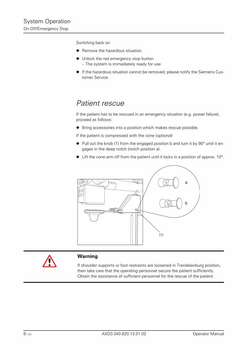
System OperationOn-Off/Emergency Stop
Switching back on
◆ Remove the hazardous situation.
◆ Unlock the red emergency stop button– The system is immediately ready for use
◆ If the hazardous situation cannot be removed, please notify the Siemens Cus-tomer Service.
Patient rescueIf the patient has to be rescued in an emergency situation (e.g. power failure), proceed as follows:
◆ Bring accessories into a position which makes rescue possible.
If the patient is compressed with the cone (optional)
◆ Pull out the knob (1) from the engaged position b and turn it by 90° until it en-gages in the deep notch (notch position a).
◆ Lift the cone arm off from the patient until it locks in a position of approx. 10°.
a
b
(1)
Warning
If shoulder supports or foot restraints are loosened in Trendelenburg position, then take care that the operating personnel secure the patient sufficiently.Obtain the assistance of sufficient personnel for the rescue of the patient.
8 / 32 AXD3-340.620.13.01.02 Operator Manual
System Operation
Functional and Safety Check
Daily tests
After switching the system on
◆ Perform a visual inspection of all displays and signal lamps on the operating units.
No errors should be indicated.
Neither the radiation ON indicator on the operating units nor the radiation warning lamp in the room should light up.
Use exclusively foot switches from SIEMENS (original parts with approval) for ra-diation release.
Prior to the examination
◆ Remove unnecessary objects and equipment from the area of action of the system.
◆ Remove unnecessary accessories from the system accessory rails and the primary collimator.
◆ Attach the devices required for patient positioning and immobilization secure-ly to the system.
◆ Attach all safety-related accessory parts correctly (e.g. footboard, grip protec-tion strip, handgrip, handgrip strip) and make sure they are properly secured.
◆ Clean any contrast agent residues from the patient table, protective plate and spotfilm device cover.
Recommendation:
As a test, take a full-format exposure using the largest possible format.
Warning
If the radiation ON indicator or a radiation warning lamp lights up, or a live fluo-roscopic image (not LIH) appears on the monitor without actuating a switch
◆ immediately switch the X-ray system off using the emergency shutdown button and
◆ notify the SIEMENS Uptime Service.
AXIOM Iconos R200 AXD3-340.620.13.01.02 9 / 32
System OperationFunctional and Safety Check
◆ Run a functional test of the STOP buttons by– performing an arbitrary system movement and– pressing the STOP button during the movement.
The movement concerned must stop immediately.Then unlock the button (turn it clockwise).
◆ Run a functional test of the proximity switches (collision protection) by– performing an arbitrary system movement and– pressing a proximity switch during the movement.
The movement concerned must stop immediately.After releasing the proximity switch, all system movements are possible again.
During the examination
◆ Check the radiation ON indicator. It should light up only– if one of the fluoroscopy switches has been pressed or– for the duration of an X-ray exposure.
◆ Check the patient positioning devices, e.g. use of the grip protection strip and handgrip.
◆ Switch system movements on only if,– there is no danger of injury to the patient or third parties,– there are no objects blocking the path of system movements.
Monthly tests◆ Run a functional test of the automatic dose rate control and automatic format
collimation as described in the “Safety” operating instructions.
Legally required tests➩ Inform yourself in the “Safety” operating instructions.
Warning
If radiation (fluoroscopy, digital radiography) is released and the radiation ON in-dicator lights up but no fluoroscopic image appears on the monitor (error in the television chain)
◆ immediately switch the system off using the emergency shutdown button and
◆ notify the SIEMENS Uptime Service.
10 / 32 AXD3-340.620.13.01.02 Operator Manual
System Operation
System Settings
General notes
Collision protection / Safety areas
❏ All system movements stop when a collision protection device is activated.
❏ The movement is stopped when a collision zone is reached.
3D support ❏ If the 3D support (optional) is not in its park position, then the system move-ments are disabled.
This system movement is enabled by simultaneously actuating the bypass key and an operating element.
◆ Press and hold this key
◆ Start the system movement after 2s.
Operating elements for system positions
❏ Operating elements with deadman functions
All operating elements for the system settings are designed as deadman func-tion, i.e. system settings are active only as long as the operating element is actu-ated.
❏ Operating elements with LEDs
LED lights up: function is selected
LED does not light up: function is deselected
LED flashes: selected function is not yet concluded or message about a particular status (see relevant chapter for description).
P
Warning
Immediately press the nearest STOP button in the case ofdanger to the patient.
All system movements are stopped.
◆ After removing the cause of the danger, unlock the STOP button by turning it to the right.
AXIOM Iconos R200 AXD3-340.620.13.01.02 11 / 32
System OperationSystem Settings
Object-dependent system settings
The agreement of the actuation direction of the operating element with the movement of the X-ray system (stand with tube assembly and primary collimator, image receptor unit with image intensifier and spotfilm device) depends upon the selected object setting.
❏ Left LED lights up: ”Object setting oriented to the monitor” is selected
❏ Right LED lights up: ”Object setting oriented to the system” is selected
Only possible from the system remote control console for the following move-ments:
– Moving the X-ray system longitudinally– Moving the tabletop longitudinally/transversely
Start positions
Automatically determined system settings are performed with the Start button depending upon the selected operating mode (tomography, Periscanning, Peristepping, scanning technique).
LED flashes: the approved system settings are not yet concluded.
LED does not light up: the approved system settings are concluded.
General notes on error messages
The system is constantly monitored internally during operation.
When a fault is detected, the system is blocked and the fault is displayed as error in the message line of the integrated generator control console and stored.
Cancelling blocking:
◆ Briefly press the exposure release button on the generator ON/OFF console up to the 1st pressure point and let go again. Don’t press more!– The fault message is cancelled as a rule
However, if an error message is still displayed, there is an error.
◆ Call the Siemens Uptime Service
Start
Further operation of the system may be only under increased attention of the user.
12 / 32 AXD3-340.620.13.01.02 Operator Manual
System OperationSystem Settings
Behavior of the system settings in the case of a fault
If there is a fault while actuating one of the following movements– tilting the table down/up– moving the tabletop longitudinally– moving the X-ray system transversely
then these movements are stopped and the fault is displayed as an error in the message line of the integrated generator control console and stored.
Cancelling the fault:
◆ Briefly press the exposure release button on the generator ON/OFF console up to the 1st pressure point and let go again. Don’t press more!.– The fault is cancelled as a rule
Actuating the same movement again
If a fault occurs again when the same movement is actuated, then these move-ments are once again stopped and the fault is displayed as an error in the mes-sage line of the integrated generator control console and stored.
Cancelling the fault:
◆ Briefly press the exposure release button on the generator ON/OFF console up to the 1st pressure point and let go again. Don’t press more!.– The fault is cancelled as a rule by this
Actuating the same movement again
If the same movement is actuated again and there is a fault once again, then a warning signal (whistle) sounds and this movement is blocked. The following er-ror message is displayed in the message line of the integrated generator control console:
“Severe error, please call service”
All other movements are possible only step by step. A warning signal (whistle) sounds on actuating and during the movement.
◆ Rescue the patient.
◆ Call the Siemens Uptime Service
Warning
Collision monitoring is inoperable.
The operator is responsible for avoiding collisions of the system with objects and the floor.
◆ Actuate system movements only with direct visual control.
AXIOM Iconos R200 AXD3-340.620.13.01.02 13 / 32
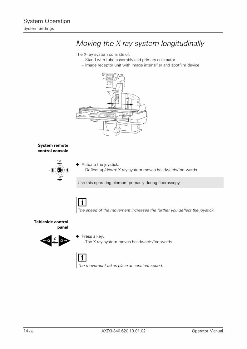
System OperationSystem Settings
Moving the X-ray system longitudinallyThe X-ray system consists of:
– Stand with tube assembly and primary collimator– Image receptor unit with image intensifier and spotfilm device
System remotecontrol console
◆ Actuate the joystick.– Deflect up/down: X-ray system moves headwards/footwards
Tableside controlpanel
◆ Press a key.– The X-ray system moves headwards/footwards
AX
IOM
Use this operating element primarily during fluoroscopy.
The speed of the movement increases the further you deflect the joystick.
The movement takes place at constant speed.
14 / 32 AXD3-340.620.13.01.02 Operator Manual
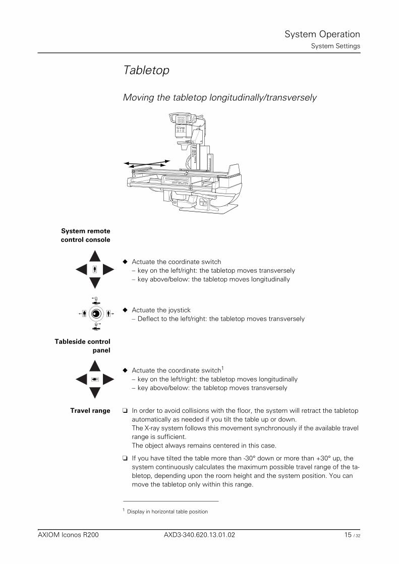
System OperationSystem Settings
Tabletop
Moving the tabletop longitudinally/transversely
System remotecontrol console
◆ Actuate the coordinate switch– key on the left/right: the tabletop moves transversely– key above/below: the tabletop moves longitudinally
◆ Actuate the joystick– Deflect to the left/right: the tabletop moves transversely
Tableside controlpanel
◆ Actuate the coordinate switch1
– key on the left/right: the tabletop moves longitudinally– key above/below: the tabletop moves transversely
Travel range ❏ In order to avoid collisions with the floor, the system will retract the tabletop automatically as needed if you tilt the table up or down.The X-ray system follows this movement synchronously if the available travel range is sufficient.The object always remains centered in this case.
❏ If you have tilted the table more than -30° down or more than +30° up, the system continuously calculates the maximum possible travel range of the ta-bletop, depending upon the room height and the system position. You can move the tabletop only within this range.
AX
IOM
1 Display in horizontal table position
AXIOM Iconos R200 AXD3-340.620.13.01.02 15 / 32
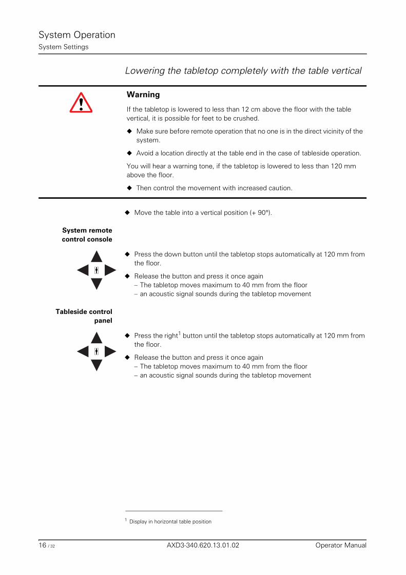
System OperationSystem Settings
Lowering the tabletop completely with the table vertical
◆ Move the table into a vertical position (+ 90°).
System remotecontrol console
◆ Press the down button until the tabletop stops automatically at 120 mm from the floor.
◆ Release the button and press it once again– The tabletop moves maximum to 40 mm from the floor– an acoustic signal sounds during the tabletop movement
Tableside controlpanel
◆ Press the right1 button until the tabletop stops automatically at 120 mm from the floor.
◆ Release the button and press it once again– The tabletop moves maximum to 40 mm from the floor– an acoustic signal sounds during the tabletop movement
Warning
If the tabletop is lowered to less than 12 cm above the floor with the table vertical, it is possible for feet to be crushed.
◆ Make sure before remote operation that no one is in the direct vicinity of the system.
◆ Avoid a location directly at the table end in the case of tableside operation.
You will hear a warning tone, if the tabletop is lowered to less than 120 mm above the floor.
◆ Then control the movement with increased caution.
1 Display in horizontal table position
16 / 32 AXD3-340.620.13.01.02 Operator Manual
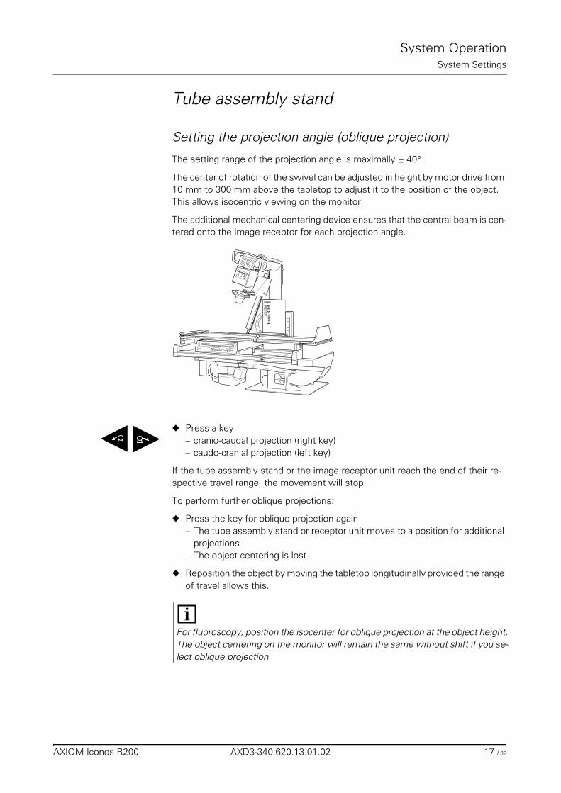
System OperationSystem Settings
Tube assembly stand
Setting the projection angle (oblique projection)
The setting range of the projection angle is maximally ± 40°.
The center of rotation of the swivel can be adjusted in height by motor drive from 10 mm to 300 mm above the tabletop to adjust it to the position of the object. This allows isocentric viewing on the monitor.
The additional mechanical centering device ensures that the central beam is cen-tered onto the image receptor for each projection angle.
◆ Press a key– cranio-caudal projection (right key)– caudo-cranial projection (left key)
If the tube assembly stand or the image receptor unit reach the end of their re-spective travel range, the movement will stop.
To perform further oblique projections:
◆ Press the key for oblique projection again– The tube assembly stand or receptor unit moves to a position for additional
projections– The object centering is lost.
◆ Reposition the object by moving the tabletop longitudinally provided the range of travel allows this.
AX
IOM
For fluoroscopy, position the isocenter for oblique projection at the object height.The object centering on the monitor will remain the same without shift if you se-lect oblique projection.
AXIOM Iconos R200 AXD3-340.620.13.01.02 17 / 32
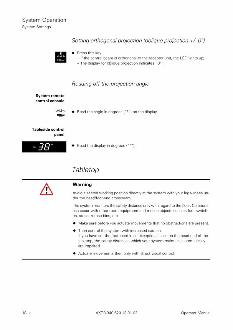
System OperationSystem Settings
Setting orthogonal projection (oblique projection +/- 0°)
◆ Press this key– If the central beam is orthogonal to the receptor unit, the LED lights up;– The display for oblique projection indicates ”0°”.
Reading off the projection angle
System remote control console
◆ Read the angle in degrees (“°“) on the display.
Tableside controlpanel
◆ Read the display in degrees (“°”).
Tabletop
˚
Warning
Avoid a seated working position directly at the system with your legs/knees un-der the head/foot-end crossbeam.
The system monitors the safety distance only with regard to the floor. Collisions can occur with other room equipment and mobile objects such as foot switch-es, steps, refuse bins, etc.
◆ Make sure before you actuate movements that no obstructions are present.
◆ Then control the system with increased caution.If you have set the footboard in an exceptional case on the head end of the tabletop, the safety distances which your system maintains automatically are impaired.
◆ Actuate movements then only with direct visual control.
18 / 32 AXD3-340.620.13.01.02 Operator Manual
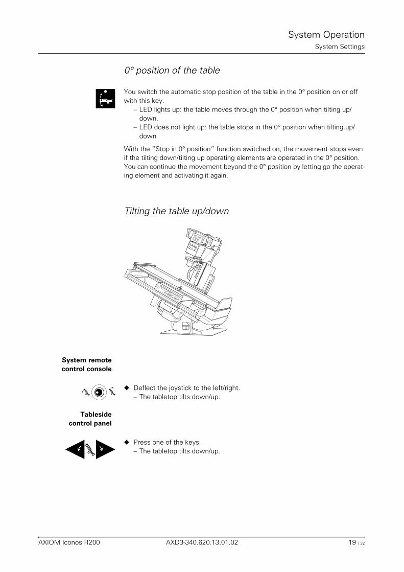
System OperationSystem Settings
0° position of the table
You switch the automatic stop position of the table in the 0° position on or off with this key.
– LED lights up: the table moves through the 0° position when tilting up/down.
– LED does not light up: the table stops in the 0° position when tilting up/down
With the “Stop in 0° position” function switched on, the movement stops even if the tilting down/tilting up operating elements are operated in the 0° position.You can continue the movement beyond the 0° position by letting go the operat-ing element and activating it again.
Tilting the table up/down
System remote control console
◆ Deflect the joystick to the left/right.– The tabletop tilts down/up.
Tablesidecontrol panel
◆ Press one of the keys.– The tabletop tilts down/up.
AXIO
M
AXIOM Iconos R200 AXD3-340.620.13.01.02 19 / 32
System OperationSystem Settings
Limitations when tilting in Trendelenburg position:
Tabletop tilting stops when the distance table (Image Intensifier) to floor is less than 40 mm.
To further tilt the table,
◆ Release the joystick/button and press it once again.– Spotfilm device and tabletop move footwards until table tilting is possible
again;– an acoustic signal sounds during tilting.
Reading the table tilt
System remote control console
◆ Read the tilt in degrees (“°”) on the display.
Tableside controlpanel
◆ Read the display in degrees (“°”).
The movement always stop automatically in the 0° position of the tabletop if the “Stop in 0° position” function is switched on.
When tilting the table down to a Trendelenburg position >15°, the shoulder sup-ports supplied or the foot restraints available as optional accessory must be used to secure the patient. The weight of the patient must not exceed 180 kg.In the case of a Trendelenburg position >45°, the foot restraints available as op-tional accessory must be used in addition to the shoulder supports. The weight of the patient must not exceed 180 kg.In the case of a Trendelenburg position >45°, the weight of the patient must not exceed 150 kg.
˚
20 / 32 AXD3-340.620.13.01.02 Operator Manual
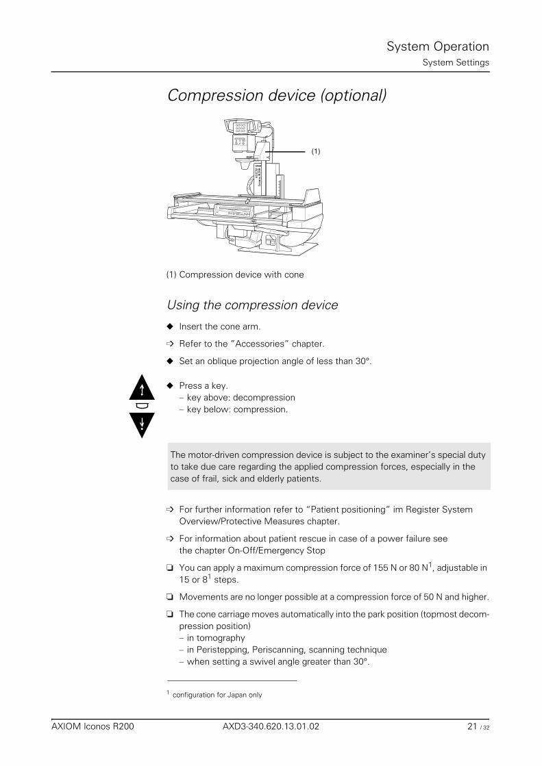
System OperationSystem Settings
Compression device (optional)
(1) Compression device with cone
Using the compression device
◆ Insert the cone arm.
➩ Refer to the ”Accessories” chapter.
◆ Set an oblique projection angle of less than 30°.
◆ Press a key.– key above: decompression– key below: compression.
➩ For further information refer to “Patient positioning” im Register System Overview/Protective Measures chapter.
➩ For information about patient rescue in case of a power failure see the chapter On-Off/Emergency Stop
❏ You can apply a maximum compression force of 155 N or 80 N1, adjustable in 15 or 81 steps.
❏ Movements are no longer possible at a compression force of 50 N and higher.
❏ The cone carriage moves automatically into the park position (topmost decom-pression position)– in tomography– in Peristepping, Periscanning, scanning technique– when setting a swivel angle greater than 30°.
(1)
AX
IOM
The motor-driven compression device is subject to the examiner’s special duty to take due care regarding the applied compression forces, especially in the case of frail, sick and elderly patients.
1 configuration for Japan only
AXIOM Iconos R200 AXD3-340.620.13.01.02 21 / 32
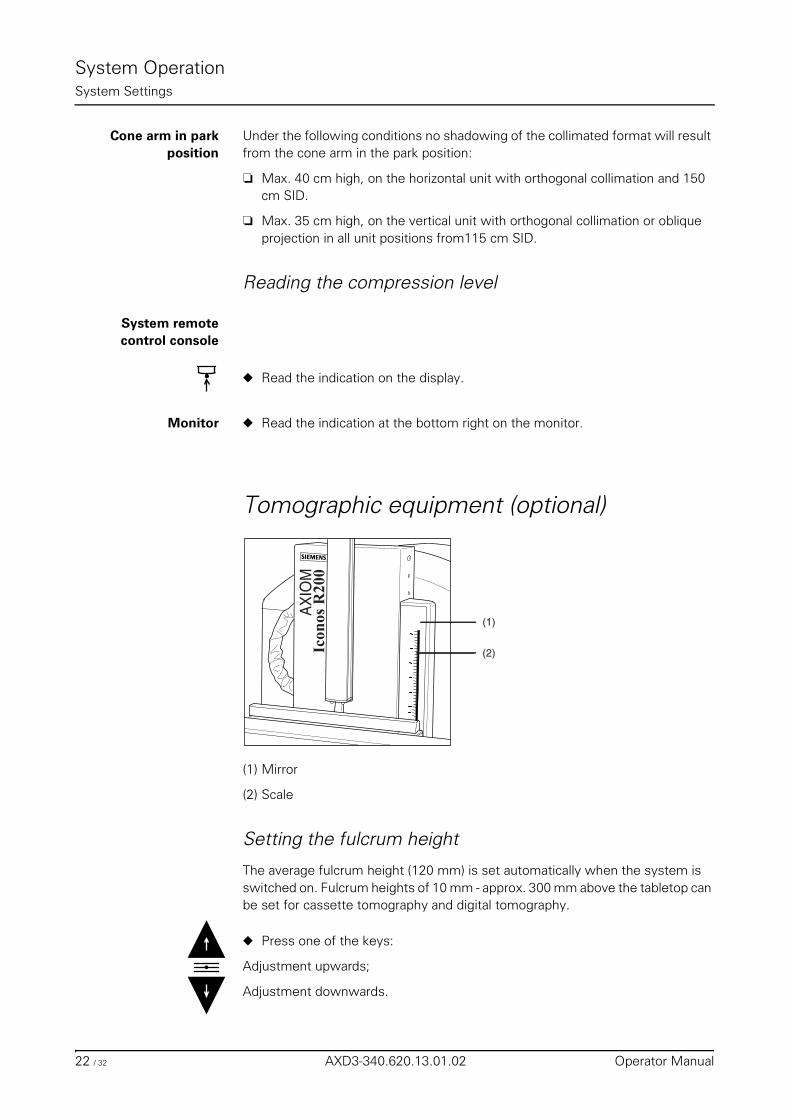
System OperationSystem Settings
Cone arm in parkposition
Under the following conditions no shadowing of the collimated format will result from the cone arm in the park position:
❏ Max. 40 cm high, on the horizontal unit with orthogonal collimation and 150 cm SID.
❏ Max. 35 cm high, on the vertical unit with orthogonal collimation or oblique projection in all unit positions from115 cm SID.
Reading the compression level
System remotecontrol console
◆ Read the indication on the display.
Monitor ◆ Read the indication at the bottom right on the monitor.
Tomographic equipment (optional)
(1) Mirror
(2) Scale
Setting the fulcrum height
The average fulcrum height (120 mm) is set automatically when the system is switched on. Fulcrum heights of 10 mm - approx. 300 mm above the tabletop can be set for cassette tomography and digital tomography.
◆ Press one of the keys:
Adjustment upwards;
Adjustment downwards.
(1)
(2)
AX
IOM
22 / 32 AXD3-340.620.13.01.02 Operator Manual
System OperationSystem Settings
Switching on the fulcrum height light localizer
◆ Press one of the keys briefly.– The light localizer goes out automatically after approx. 20s.
Reading the fulcrum height
The fulcrum height display on the system remote control console is decisive for all examinations.
System remotecontrol console
◆ Read the display (display in ”mm”).
on the system Switch the fulcrum height light localizer on. You have 2 possibilities of reading the fulcrum height:
Direct method (light line on the object):
◆ Look from the right side in the mirror on the system.– You will see the projection of a red laser light line directly on the patient.– This light line indicates the set fulcrum height directly on the patient.
Indirect method (on scale):
◆ Look at the scale next to the mirror on the system.– You will see a red light mark there.
◆ Read the scale value indicated by the light mark.– One division corresponds to 0.5 cm.
Press briefly and the fulcrum height changes by 1 mm.
Press longer, the fulcrum height changes continuously in steps of 1 mm.
AXIOM Iconos R200 AXD3-340.620.13.01.02 23 / 32
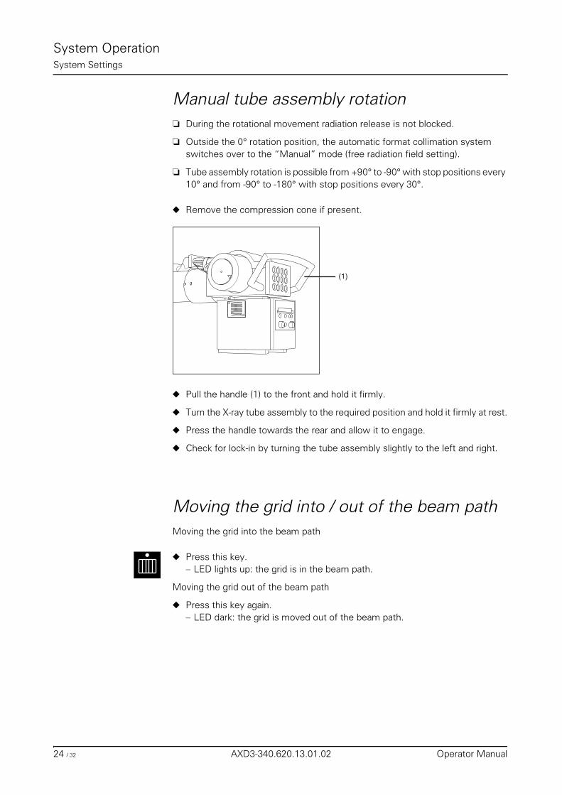
System OperationSystem Settings
Manual tube assembly rotation❏ During the rotational movement radiation release is not blocked.
❏ Outside the 0° rotation position, the automatic format collimation system switches over to the “Manual” mode (free radiation field setting).
❏ Tube assembly rotation is possible from +90° to -90° with stop positions every 10° and from -90° to -180° with stop positions every 30°.
◆ Remove the compression cone if present.
◆ Pull the handle (1) to the front and hold it firmly.
◆ Turn the X-ray tube assembly to the required position and hold it firmly at rest.
◆ Press the handle towards the rear and allow it to engage.
◆ Check for lock-in by turning the tube assembly slightly to the left and right.
Moving the grid into / out of the beam pathMoving the grid into the beam path
◆ Press this key.– LED lights up: the grid is in the beam path.
Moving the grid out of the beam path
◆ Press this key again.– LED dark: the grid is moved out of the beam path.
(1)
24 / 32 AXD3-340.620.13.01.02 Operator Manual
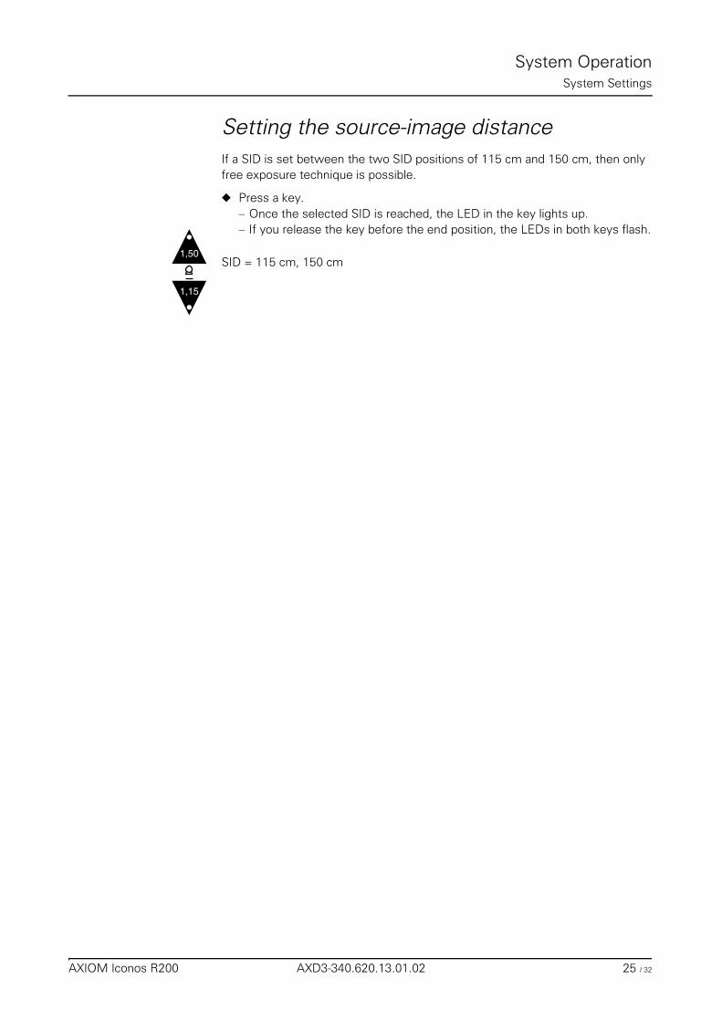
System OperationSystem Settings
Setting the source-image distanceIf a SID is set between the two SID positions of 115 cm and 150 cm, then only free exposure technique is possible.
◆ Press a key.– Once the selected SID is reached, the LED in the key lights up.– If you release the key before the end position, the LEDs in both keys flash.
SID = 115 cm, 150 cm1,50
1,15
AXIOM Iconos R200 AXD3-340.620.13.01.02 25 / 32

System OperationSystem Settings
26 / 32 AXD3-340.620.13.01.02 Operator Manual
System Operation
Setting the Image Geometry
Limiting the radiation field (collimation)
Rectangular and /or iris collimation
Fluoroscopy andDigital Radiography (DR)
(optional)
You can view the collimation on the monitor under fluoroscopy. The default is iris collimation.
The collimator is opened or closed synchronously and symmetrically to the image receptor center.
Within the selected image intensifier format, the radiation field can be collimated basically as desired and you can switch over from iris to rectangular collimation.
On selection of a lower ZOOM level (larger field) or image intensifier full format, the rectangular and iris collimation are retained, or the larger field is collimated (can be configured).
On selection of a higher ZOOM level (smaller field), the collimator always switch-es to the smaller field (iris collimation).
Cassette exposure The system switches over automatically to rectangular collimation on selection of the spotfilm device or tabletop cassette exposure technique.It is not possible to select iris collimation.
Selection / deselection
Use the key on the system remote control console for selection / deselection.
◆ Press this key– Rectangular collimation is selected: left LED lights up.– Iris collimation is selected: right LED lights up.
The maximum possible collimator aperture is never greater than the selected im-age intensifier format.
The edge of the diaphragm must be visible in the fluoroscopic image.
AXIOM Iconos R200 AXD3-340.620.13.01.02 27 / 32
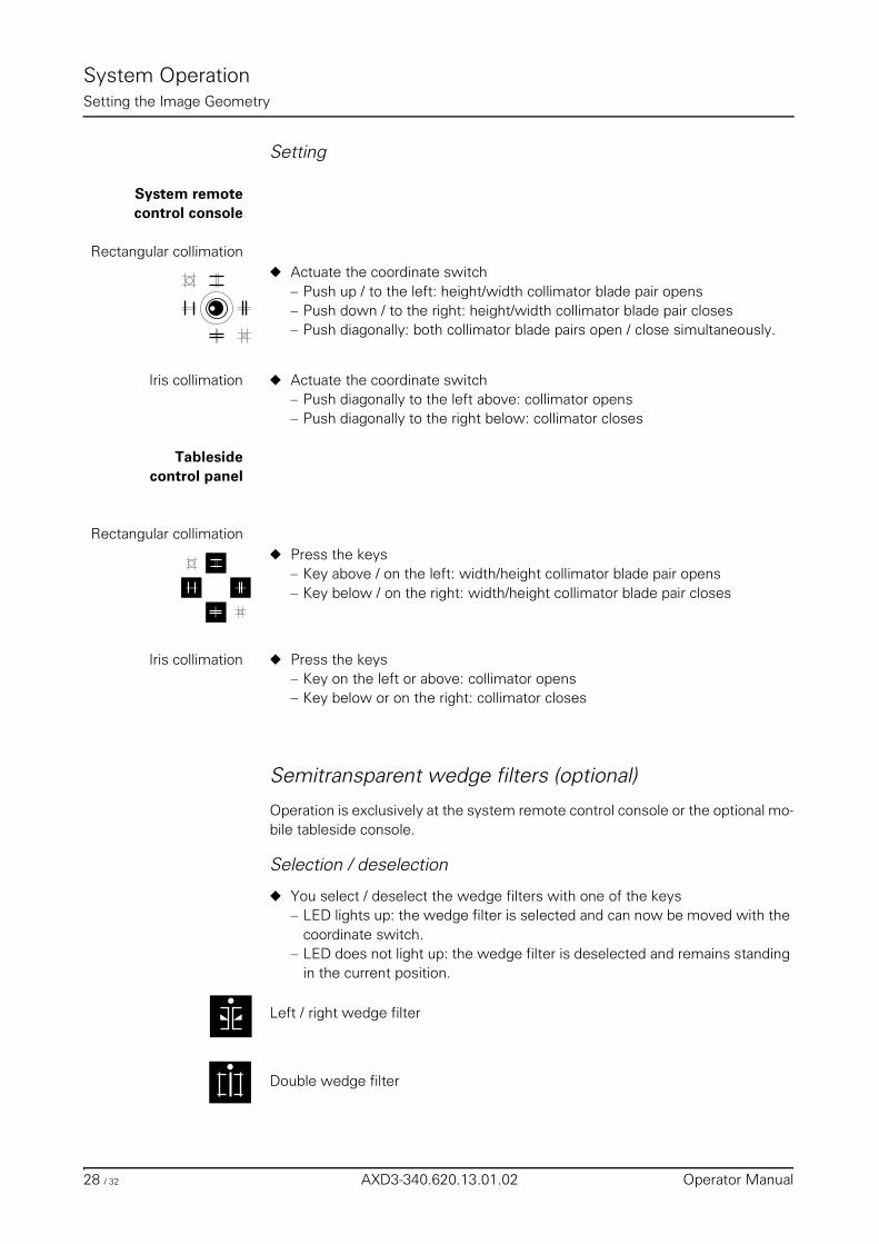
System OperationSetting the Image Geometry
Setting
System remotecontrol console
Rectangular collimation◆ Actuate the coordinate switch
– Push up / to the left: height/width collimator blade pair opens– Push down / to the right: height/width collimator blade pair closes– Push diagonally: both collimator blade pairs open / close simultaneously.
Iris collimation ◆ Actuate the coordinate switch– Push diagonally to the left above: collimator opens– Push diagonally to the right below: collimator closes
Tablesidecontrol panel
Rectangular collimation◆ Press the keys
– Key above / on the left: width/height collimator blade pair opens– Key below / on the right: width/height collimator blade pair closes
Iris collimation ◆ Press the keys– Key on the left or above: collimator opens– Key below or on the right: collimator closes
Semitransparent wedge filters (optional)
Operation is exclusively at the system remote control console or the optional mo-bile tableside console.
Selection / deselection
◆ You select / deselect the wedge filters with one of the keys– LED lights up: the wedge filter is selected and can now be moved with the
coordinate switch.– LED does not light up: the wedge filter is deselected and remains standing
in the current position.
Left / right wedge filter
Double wedge filter
28 / 32 AXD3-340.620.13.01.02 Operator Manual
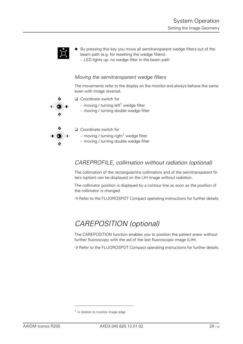
System OperationSetting the Image Geometry
◆ By pressing this key you move all semitransparent wedge filters out of the beam path (e.g. for resetting the wedge filters).– LED lights up: no wedge filter in the beam path
Moving the semitransparent wedge filters
The movements refer to the display on the monitor and always behave the same even with image reversal.
❏ Coordinate switch for
– moving / turning left1 wedge filter– moving / turning double wedge filter
❏ Coordinate switch for
– moving / turning right1 wedge filter– moving / turning double wedge filter
CAREPROFILE, collimation without radiation (optional)
The collimation of the rectangular/iris collimators and of the semitransparent fil-ters (option) can be displayed on the LIH image without radiation.
The collimator position is displayed by a contour line as soon as the position of the collimator is changed.
➩ Refer to the FLUOROSPOT Compact operating instructions for further details.
CAREPOSITION (optional)The CAREPOSITION function enables you to position the patient anew without further fluoroscopy with the aid of the last fluoroscopic image (LIH).
➩ Refer to the FLUOROSPOT Compact operating instructions for further details.
1 in relation to monitor image edge
AXIOM Iconos R200 AXD3-340.620.13.01.02 29 / 32
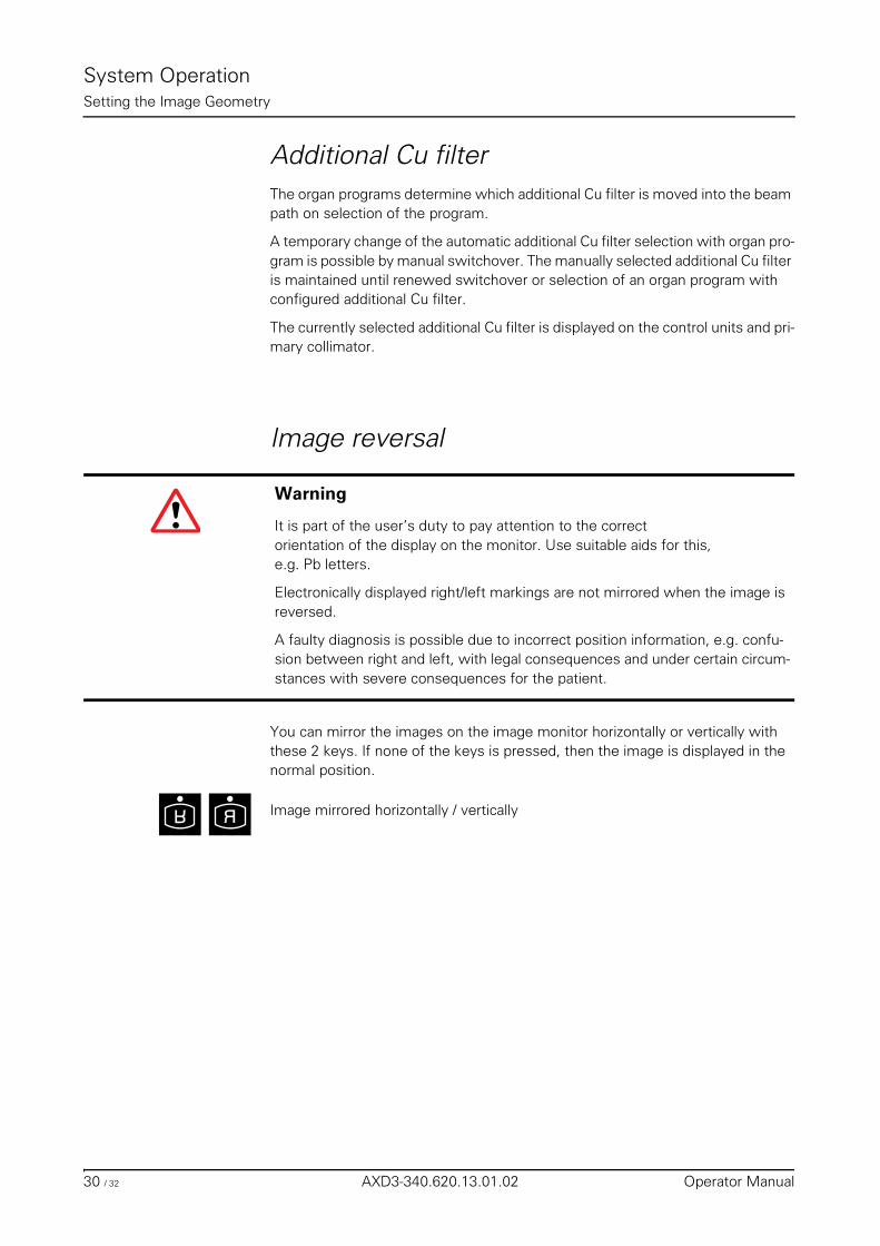
System OperationSetting the Image Geometry
Additional Cu filterThe organ programs determine which additional Cu filter is moved into the beam path on selection of the program.
A temporary change of the automatic additional Cu filter selection with organ pro-gram is possible by manual switchover. The manually selected additional Cu filter is maintained until renewed switchover or selection of an organ program with configured additional Cu filter.
The currently selected additional Cu filter is displayed on the control units and pri-mary collimator.
Image reversal
You can mirror the images on the image monitor horizontally or vertically with these 2 keys. If none of the keys is pressed, then the image is displayed in the normal position.
Image mirrored horizontally / vertically
Warning
It is part of the user’s duty to pay attention to the correct orientation of the display on the monitor. Use suitable aids for this, e.g. Pb letters.
Electronically displayed right/left markings are not mirrored when the image isreversed.
A faulty diagnosis is possible due to incorrect position information, e.g. confu-sion between right and left, with legal consequences and under certain circum-stances with severe consequences for the patient.
RR
30 / 32 AXD3-340.620.13.01.02 Operator Manual
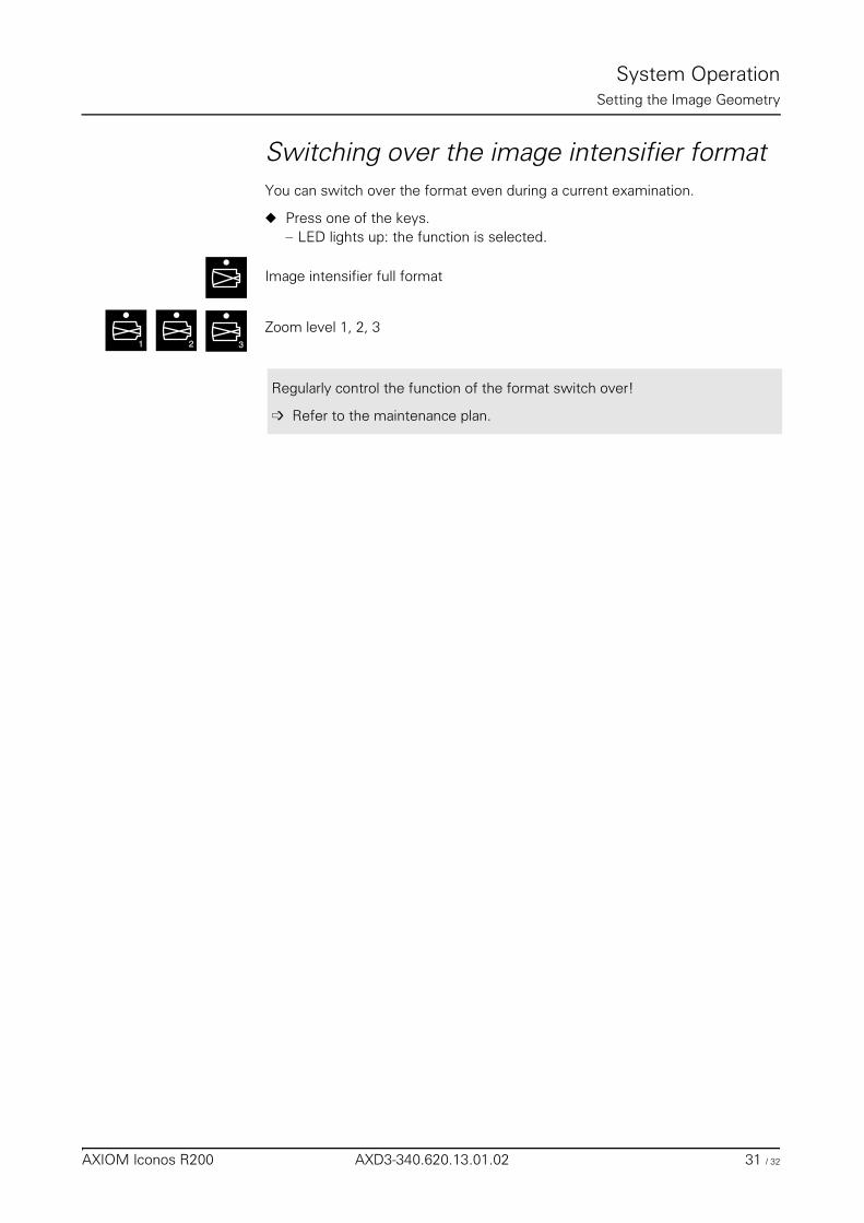
System OperationSetting the Image Geometry
Switching over the image intensifier formatYou can switch over the format even during a current examination.
◆ Press one of the keys.– LED lights up: the function is selected.
Image intensifier full format
Zoom level 1, 2, 31 32
Regularly control the function of the format switch over!
➩ Refer to the maintenance plan.
AXIOM Iconos R200 AXD3-340.620.13.01.02 31 / 32

System OperationSetting the Image Geometry
32 / 32 AXD3-340.620.13.01.02 Operator Manual
ExaminationTable of Contents
Operator Manual
Examination
Chapter: Transferring and Positioning the Patient
General information ............................................................................................................ 5
Positioning the patient ........................................................................................................ 5
Chapter: Fluoroscopy
Fluoroscopy operating modes ............................................................................................ 7
Selecting the fluoroscopy operating mode ......................................................................... 7
Changing the selection of the fluoroscopy operating mode ............................................... 7Fluoroscopy with Supervision (optional) ............................................................................... 8Pulsed fluoroscopy (optional) ............................................................................................. 8Roadmap ...................................................................................................................... 8
Releasing fluoroscopy ........................................................................................................ 9
Fluoroscopic data ............................................................................................................... 9Display of the kV and mA values ........................................................................................ 9Display of the fluoroscopic time ......................................................................................... 9Display of the area dose product (optional) ........................................................................... 9Resetting the fluoroscopic data ........................................................................................ 10
Automatic fluoroscopic control ......................................................................................... 10Selecting automatic fluoroscopic control ............................................................................ 10Stop function ............................................................................................................... 10Fluoroscopic curves ....................................................................................................... 10
Fluoroscopy time limit ...................................................................................................... 11
Fluoroscopy warning signal .............................................................................................. 11
Automatic format collimation in fluoroscopy .................................................................... 11
Fluoroscopy programs ...................................................................................................... 11
Dose reduction ................................................................................................................. 12
AXIOM Iconos R200 AXD3-340.620.13.01.02 1 / 52
ExaminationTable of Contents
Chapter: Cassette Exposures in the Spotfilm Device (optional)
Automatic format collimation in radiography .................................................................... 13Bucky mode ................................................................................................................. 13Semiautomatic mode ..................................................................................................... 13Fully automatic mode ..................................................................................................... 13
Cassette program ............................................................................................................. 14Cassette formats and segmentation program ..................................................................... 14Selecting the segmentation program ................................................................................. 14Format segmentation ..................................................................................................... 15
Skipping a segmentation segment ........................................................................... 15Mixed mode ........................................................................................................ 15
Loading / unloading the spotfilm device ........................................................................... 16Loading ....................................................................................................................... 16Unloading .................................................................................................................... 17
Exposure measurement for cassette exposures .............................................................. 17Arrangement of the dominants ........................................................................................ 17Selection of the dominants ............................................................................................. 18
Releasing the exposure .................................................................................................... 19
Organ programs ................................................................................................................ 19
Single exposures / serialography ...................................................................................... 19Single exposure ............................................................................................................ 19Serialography ............................................................................................................... 20
Bucky mode ...................................................................................................................... 20
Spotfilming without tomography ...................................................................................... 20
Tomography (optional) ...................................................................................................... 21Tomographic sequence .................................................................................................. 22
Chapter: Digital Radiography
Automatic format collimation in digital radio-graphy ......................................................... 23
Exposure measurement in digital radiography ................................................................. 23Arrangement of the dominants ........................................................................................ 23Selecting the dominants ................................................................................................. 24
2 / 52 AXD3-340.620.13.01.02 Operator Manual
ExaminationTable of Contents
Spotfilming without tomography ...................................................................................... 25Selection ..................................................................................................................... 25Single image - serialography ............................................................................................ 25
Changing selection ............................................................................................... 25Frame rate .......................................................................................................... 25
Releasing the exposure .................................................................................................. 26Organ programs ............................................................................................................ 26
Programs ............................................................................................................ 27Creation of programs ............................................................................................ 27Temporary changes of programs ............................................................................. 27
Tomography (optional) ...................................................................................................... 27Selection ..................................................................................................................... 27Tomographic sequence .................................................................................................. 28Releasing the exposure .................................................................................................. 29Organ programs ............................................................................................................ 29
Programs ............................................................................................................ 29Creation of programs ............................................................................................ 29Temporary changes of programs ............................................................................. 29
Periscanning ..................................................................................................................... 30General ....................................................................................................................... 30Selection ..................................................................................................................... 30Deselection ................................................................................................................. 30Releasing the exposure .................................................................................................. 31Examination procedure ................................................................................................... 31
Preparation ......................................................................................................... 31Test run .............................................................................................................. 32Scanning process ................................................................................................. 33End of the scene .................................................................................................. 33
Organ programs ............................................................................................................ 33Creation of programs ............................................................................................ 33Temporary changes of programs ............................................................................. 33
Peristepping (optional) ...................................................................................................... 34General ....................................................................................................................... 34
Programming run ................................................................................................. 35Filling run ............................................................................................................ 35
Selection ..................................................................................................................... 35Deselection ................................................................................................................. 35Releasing an exposure ................................................................................................... 36Examination procedure ................................................................................................... 36
Preparation ......................................................................................................... 36Programming run ................................................................................................. 38Filling run ............................................................................................................ 39End of scene ....................................................................................................... 39
Organ programs ............................................................................................................ 40Creation of programs ............................................................................................ 40Temporary changes of programs ............................................................................. 40
AXIOM Iconos R200 AXD3-340.620.13.01.02 3 / 52
ExaminationTable of Contents
DR-Scanning (optional) ..................................................................................................... 40General ....................................................................................................................... 40Selection ..................................................................................................................... 41Deselection ................................................................................................................. 41Image transfer .............................................................................................................. 41Releasing an exposure ................................................................................................... 41Examination procedure for abdominal survey images ........................................................... 42
Preparation ......................................................................................................... 42Moving the system and tabletop into the starting position ............................................ 43Scanning process ................................................................................................. 43End of the scene .................................................................................................. 43
Examination procedure for images of the spine and orthopedic longleg images ......................... 44Preparation ......................................................................................................... 44Moving the system and tabletop into the starting position ............................................ 45Scanning process ................................................................................................. 45End of the scene .................................................................................................. 45
Organ programs ............................................................................................................ 46Program suggestions for FLUOROSPOT Compact ...................................................... 46
Peristepping examination sequence for survey images ......................................................... 47
Chapter: Free Cassette Exposure
Collimation on exposure ................................................................................................... 49
Selecting the exposure technique .................................................................................... 49Tabletop cassette exposure or free mode .......................................................................... 49
Releasing an exposure ..................................................................................................... 50
Chapter: Cassette exposures with wall stand
Collimation during exposure ............................................................................................. 51
Selecting the exposure technique .................................................................................... 51
Releasing the exposure .................................................................................................... 52
4 / 52 AXD3-340.620.13.01.02 Operator Manual
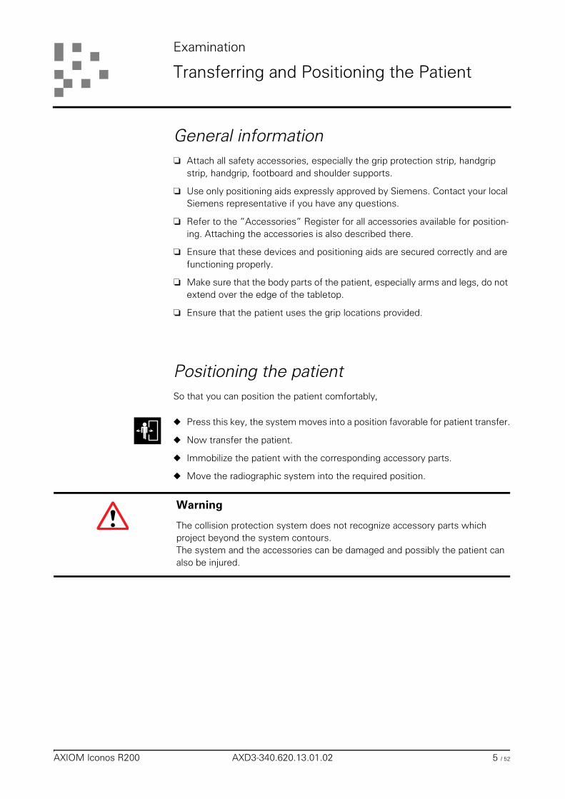
Examination
Transferring and Positioning the Patient
General information❏ Attach all safety accessories, especially the grip protection strip, handgrip
strip, handgrip, footboard and shoulder supports.
❏ Use only positioning aids expressly approved by Siemens. Contact your local Siemens representative if you have any questions.
❏ Refer to the ”Accessories” Register for all accessories available for position-ing. Attaching the accessories is also described there.
❏ Ensure that these devices and positioning aids are secured correctly and are functioning properly.
❏ Make sure that the body parts of the patient, especially arms and legs, do not extend over the edge of the tabletop.
❏ Ensure that the patient uses the grip locations provided.
Positioning the patientSo that you can position the patient comfortably,
◆ Press this key, the system moves into a position favorable for patient transfer.
◆ Now transfer the patient.
◆ Immobilize the patient with the corresponding accessory parts.
◆ Move the radiographic system into the required position.
Warning
The collision protection system does not recognize accessory parts which project beyond the system contours.The system and the accessories can be damaged and possibly the patient can also be injured.
AXIOM Iconos R200 AXD3-340.620.13.01.02 5 / 52

ExaminationTransferring and Positioning the Patient
6 / 52 AXD3-340.620.13.01.02 Operator Manual
Examination
Fluoroscopy
Fluoroscopy operating modes❏ Standard fluoroscopy (continuous fluoroscopy)
– In continuous fluoroscopy 30 (25)1 frames per second are generated by the television central control unit.
❏ Fluoroscopy with pulsed television scanning (Supervision option)
– In SUPERVISION only 15 (12.5)1 frames per second are generated. In this case fluoroscopy is applied at half the radiation dose with half the temporal resolution.
or
❏ Primary pulsed fluoroscopy (CAREVISION option)
– In pulsed fluoroscopy, the radiation is pulsed at 15 (12.5)1 or 7.5 (8.3)1 or 3
(3)1 pulses per second. In this way a corresponding dose saving with a lower temporal resolution is possible.
❏ Roadmap (only with DSA option) with standard fluoroscopy, with Supervision (optional) or pulsed fluoroscopy (optional)– Roadmap is a special fluoroscopic mode with subtraction display
Selecting the fluoroscopy operating modeAll parameters necessary for fluoroscopy are stored in organ programs.
◆ Select a corresponding organ program on the integrated generator control console.
Changing the selection of the fluoroscopy operating modeIt is possible to change the selection of the operating modes in connection with the Supervision or CAREVISION options.
The current operating mode is displayed in the operating menu of the live moni-tor.
Use the FLUOROSPOT Compact infrared control for operation.
If your system is equipped only with standard fluoroscopy, the Fluoro+ and Fluo-ro- keys have no function.
1 Values in brackets apply to VIDEOMED DHC
AXIOM Iconos R200 AXD3-340.620.13.01.02 7 / 52
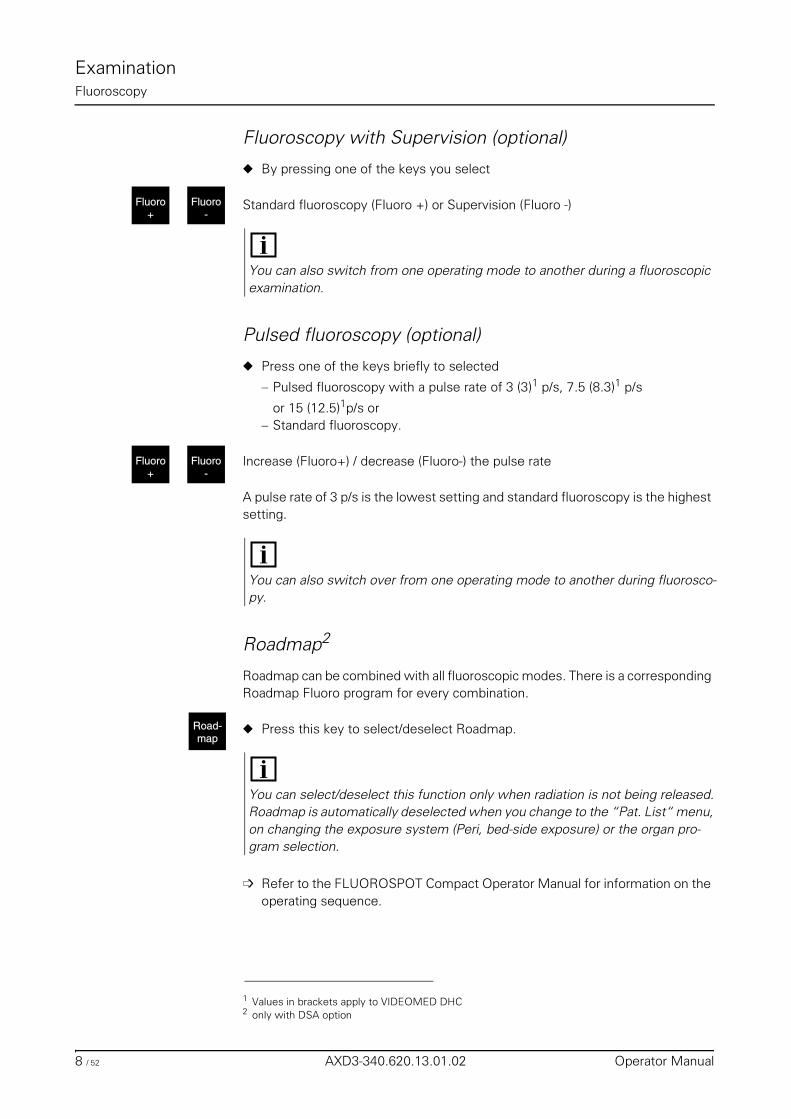
ExaminationFluoroscopy
Fluoroscopy with Supervision (optional)
◆ By pressing one of the keys you select
Standard fluoroscopy (Fluoro +) or Supervision (Fluoro -)
Pulsed fluoroscopy (optional)
◆ Press one of the keys briefly to selected
– Pulsed fluoroscopy with a pulse rate of 3 (3)1 p/s, 7.5 (8.3)1 p/s
or 15 (12.5)1p/s or– Standard fluoroscopy.
Increase (Fluoro+) / decrease (Fluoro-) the pulse rate
A pulse rate of 3 p/s is the lowest setting and standard fluoroscopy is the highest setting.
Roadmap2
Roadmap can be combined with all fluoroscopic modes. There is a corresponding Roadmap Fluoro program for every combination.
◆ Press this key to select/deselect Roadmap.
➩ Refer to the FLUOROSPOT Compact Operator Manual for information on the operating sequence.
Fluoro-
Fluoro+
You can also switch from one operating mode to another during a fluoroscopic examination.
1 Values in brackets apply to VIDEOMED DHC
Fluoro-
Fluoro+
You can also switch over from one operating mode to another during fluorosco-py.
2 only with DSA option
Road-map
You can select/deselect this function only when radiation is not being released.Roadmap is automatically deselected when you change to the “Pat. List“ menu, on changing the exposure system (Peri, bed-side exposure) or the organ pro-gram selection.
8 / 52 AXD3-340.620.13.01.02 Operator Manual
ExaminationFluoroscopy
Releasing fluoroscopy❏ Use the foot switch to release fluoroscopy.
❏ Radiation is released as long as you continue to press the footswitch for fluo-roscopy. After you let the switch go, the last image is retained and displayed on the monitor (LIH).
❏ With the red emergency STOP button actuated, fluoroscopy can be switched back on consciously after letting the fluoroscopy switch go and pressing it again.
❏ A patient folder must be created and selected in the FLUOROSPOT Compact.
❏ No processing functions apart from storing the image are possible during flu-oroscopy.
❏ The radiation ON indicators must light up.
Fluoroscopic dataThe fluoroscopic data of kV, mA, time and area dose product (optional) are dis-played on the integrated generator control console.
Display of the kV and mA values
❏ During fluoroscopy:– Running display of the momentary kV and mA values
❏ After the end of fluoroscopy:– kV and mA mean value of the examination
Display of the fluoroscopic time
Continuous display of the time accumulating in the examination in minutes.
Display of the area dose product (optional)
Continuous display of the area dose product accumulating in the examination.
Warning
If these radiation ON indicators light up although no switch has been actuated and the current fluoroscopic image cannot be seen on the monitor:
◆ Switch the system off immediately!
◆ Notify the SIEMENS Uptime Service.
◆ Discontinue use of the system.
AXIOM Iconos R200 AXD3-340.620.13.01.02 9 / 52
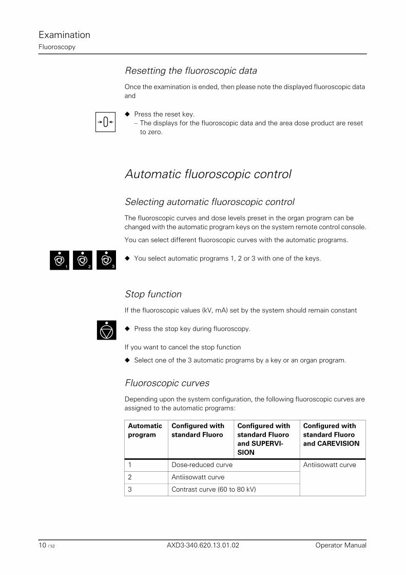
ExaminationFluoroscopy
Resetting the fluoroscopic data
Once the examination is ended, then please note the displayed fluoroscopic data and
◆ Press the reset key.– The displays for the fluoroscopic data and the area dose product are reset
to zero.
Automatic fluoroscopic control
Selecting automatic fluoroscopic control
The fluoroscopic curves and dose levels preset in the organ program can be changed with the automatic program keys on the system remote control console.
You can select different fluoroscopic curves with the automatic programs.
◆ You select automatic programs 1, 2 or 3 with one of the keys.
Stop function
If the fluoroscopic values (kV, mA) set by the system should remain constant
◆ Press the stop key during fluoroscopy.
If you want to cancel the stop function
◆ Select one of the 3 automatic programs by a key or an organ program.
Fluoroscopic curves
Depending upon the system configuration, the following fluoroscopic curves are assigned to the automatic programs:
Automatic program
Configured with standard Fluoro
Configured with standard Fluoro and SUPERVI-SION
Configured with standard Fluoro and CAREVISION
1 Dose-reduced curve Antiisowatt curve
2 Antiisowatt curve
3 Contrast curve (60 to 80 kV)
1 32
10 / 52 AXD3-340.620.13.01.02 Operator Manual
ExaminationFluoroscopy
Fluoroscopy time limitFluoroscopy is switched off automatically and can no longer be switched on after a fluoroscopy time of 10 minutes1.
To continue working
◆ let the fluoroscopy switch go and press it once again.
Fluoroscopy warning signalAn acoustic signal sounds after a fluoroscopy time of maximum 5 minutes2.
◆ The signal disappears when you press the key on the Fluorospot Compact.
The time for the acoustic signal can be reset to zero at any time.
Automatic format collimation in fluoroscopyAutomatic format collimation is also switched on automatically when fluoroscopy is released.
I.e. the fluoroscopic field is never larger than the selected image intensifier for-mat.
You can limit the fluoroscopic field to the required size with the corresponding operating elements within this area.
Fluoroscopy programsAll parameters necessary for fluoroscopy are stored in programs.
The following programs can be stored:– Standard fluoroscopy– Supervision– Pulsed fluoroscopy (Carevision) – Roadmap standard fluoroscopy – Roadmap Supervision – Roadmap pulsed fluoroscopy
➩ Refer to the Fluorospot Compact Operator Manual.
1 Can be changed on request by SIEMENS Uptime Service, under compliance with the national regulations.
2 Can be configured from 1 to 5 minutes by the SIEMENS Uptime Service
AXIOM Iconos R200 AXD3-340.620.13.01.02 11 / 52
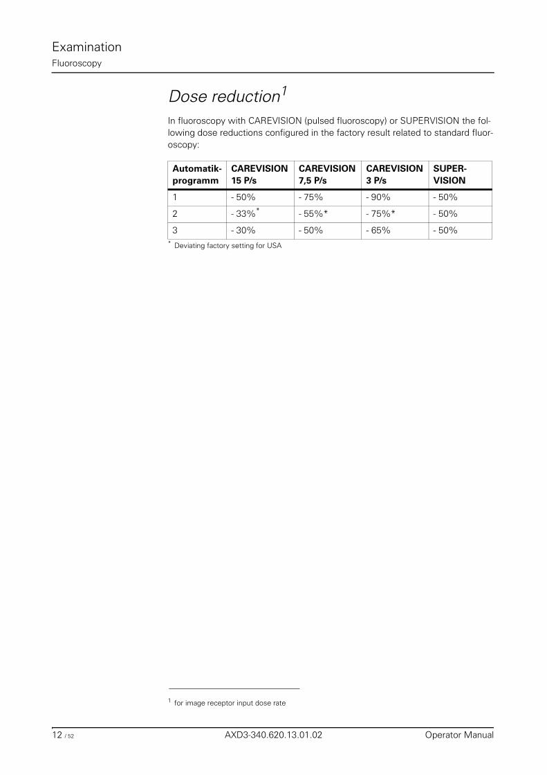
ExaminationFluoroscopy
Dose reduction1
In fluoroscopy with CAREVISION (pulsed fluoroscopy) or SUPERVISION the fol-lowing dose reductions configured in the factory result related to standard fluor-oscopy:
1 for image receptor input dose rate
Automatik-programm
CAREVISION15 P/s
CAREVISION7,5 P/s
CAREVISION3 P/s
SUPER-VISION
1 - 50% - 75% - 90% - 50%
2 - 33%*
* Deviating factory setting for USA
- 55%* - 75%* - 50%
3 - 30% - 50% - 65% - 50%
12 / 52 AXD3-340.620.13.01.02 Operator Manual
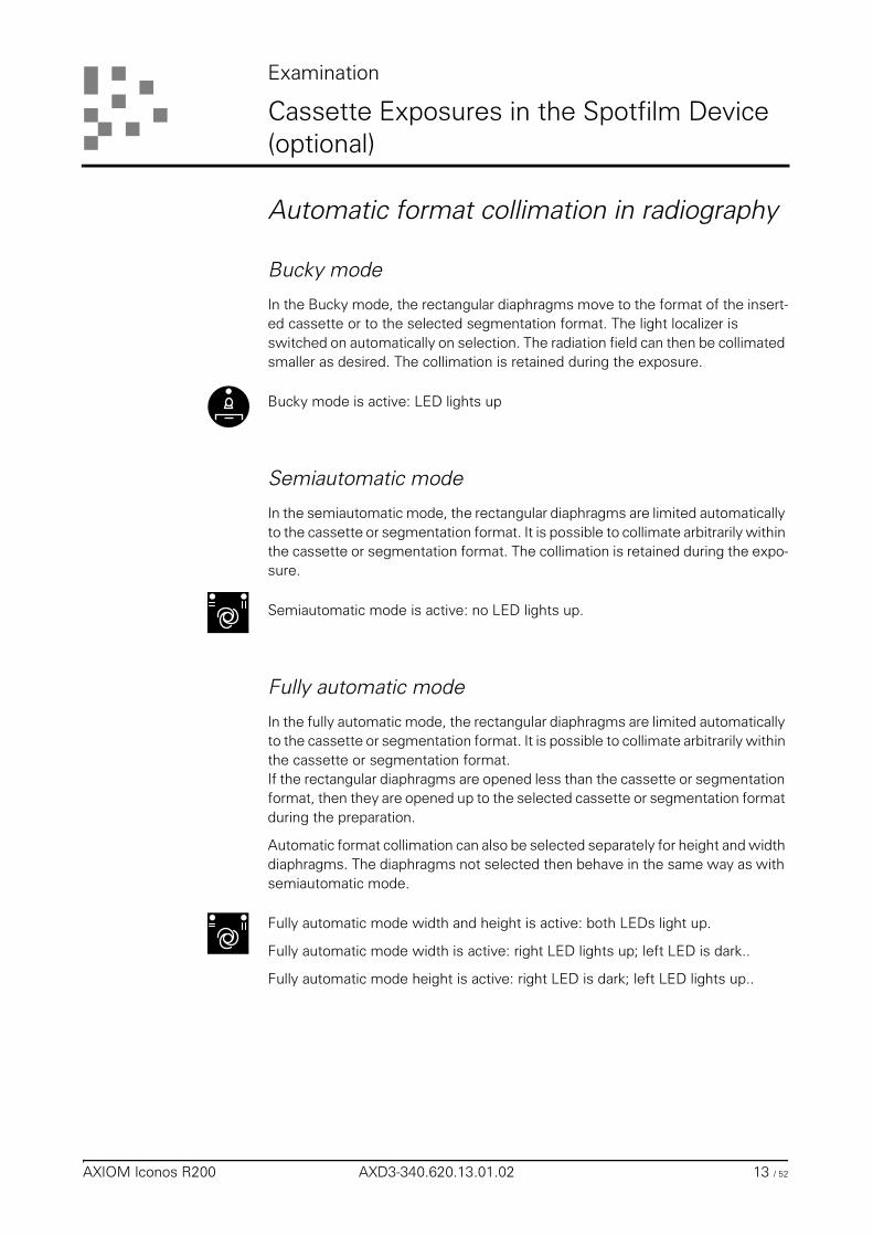
Examination
Cassette Exposures in the Spotfilm Device (optional)
Automatic format collimation in radiography
Bucky mode
In the Bucky mode, the rectangular diaphragms move to the format of the insert-ed cassette or to the selected segmentation format. The light localizer is switched on automatically on selection. The radiation field can then be collimated smaller as desired. The collimation is retained during the exposure.
Bucky mode is active: LED lights up
Semiautomatic mode
In the semiautomatic mode, the rectangular diaphragms are limited automatically to the cassette or segmentation format. It is possible to collimate arbitrarily within the cassette or segmentation format. The collimation is retained during the expo-sure.
Semiautomatic mode is active: no LED lights up.
Fully automatic mode
In the fully automatic mode, the rectangular diaphragms are limited automatically to the cassette or segmentation format. It is possible to collimate arbitrarily within the cassette or segmentation format.If the rectangular diaphragms are opened less than the cassette or segmentation format, then they are opened up to the selected cassette or segmentation format during the preparation.
Automatic format collimation can also be selected separately for height and width diaphragms. The diaphragms not selected then behave in the same way as with semiautomatic mode.
Fully automatic mode width and height is active: both LEDs light up.
Fully automatic mode width is active: right LED lights up; left LED is dark..
Fully automatic mode height is active: right LED is dark; left LED lights up..
AXIOM Iconos R200 AXD3-340.620.13.01.02 13 / 52
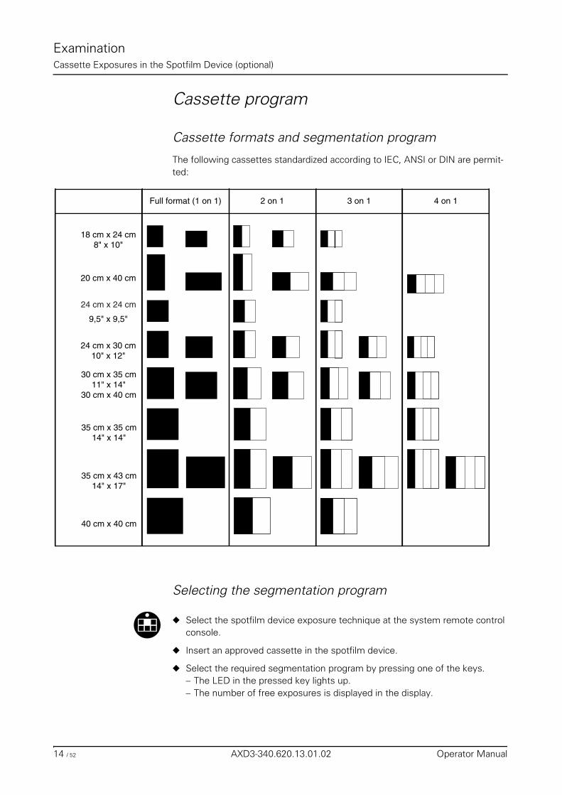
ExaminationCassette Exposures in the Spotfilm Device (optional)
Cassette program
Cassette formats and segmentation program
The following cassettes standardized according to IEC, ANSI or DIN are permit-ted:
Selecting the segmentation program
◆ Select the spotfilm device exposure technique at the system remote control console.
◆ Insert an approved cassette in the spotfilm device.
◆ Select the required segmentation program by pressing one of the keys.– The LED in the pressed key lights up.– The number of free exposures is displayed in the display.
18 cm x 24 cm8" x 10"
9,5" x 9,5"
24 cm x 30 cm10" x 12"
30 cm x 35 cm11" x 14"
30 cm x 40 cm
35 cm x 35 cm14" x 14"
20 cm x 40 cm
35 cm x 43 cm14" x 17"
40 cm x 40 cm
Full format (1 on 1) 2 on 1 3 on 1 4 on 1
24 cm x 24 cm
14 / 52 AXD3-340.620.13.01.02 Operator Manual
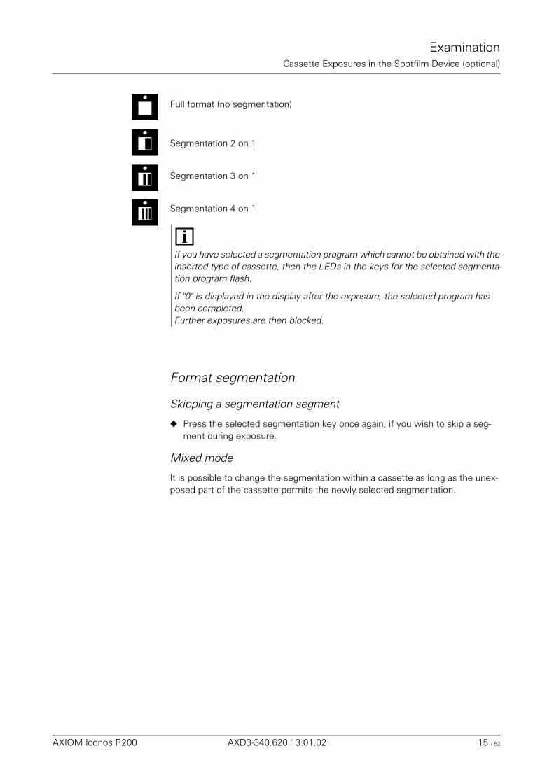
ExaminationCassette Exposures in the Spotfilm Device (optional)
Full format (no segmentation)
Segmentation 2 on 1
Segmentation 3 on 1
Segmentation 4 on 1
Format segmentation
Skipping a segmentation segment
◆ Press the selected segmentation key once again, if you wish to skip a seg-ment during exposure.
Mixed mode
It is possible to change the segmentation within a cassette as long as the unex-posed part of the cassette permits the newly selected segmentation.
If you have selected a segmentation program which cannot be obtained with the inserted type of cassette, then the LEDs in the keys for the selected segmenta-tion program flash.
If "0" is displayed in the display after the exposure, the selected program has been completed.Further exposures are then blocked.
AXIOM Iconos R200 AXD3-340.620.13.01.02 15 / 52
ExaminationCassette Exposures in the Spotfilm Device (optional)
Loading / unloading the spotfilm device
Loading
LED lights up: Cassette in unloading position.
◆ Insert the cassette with the smooth side upwards and insert at least 2/3 of the cassette width into the loading shaft.– The cassette is drawn in automatically and parked in the spotfilm device.– At the same time the cassette format is measured and the LED in the cor-
responding segmentation key lights up.– The cassette size is shown in the display of the system remote control con-
sole.
If a cassette format which is not approved is used, the cassette moves automat-ically back into the loading position.
The cassette does not appear in the loading slot:
◆ Tilt the tabletop into the +45° position.
◆ Press the unloading key briefly a number of times until the cassette appears in the loading slot.
In a table position of approx. 45° to 90° it can happen that if the cassette is not inserted far enough it drops out from the loading shaft again on automatic center-ing depending on its make/type. The formats 20 x 40 cm, 18 x 24 cm and24 x 30 cm inserted in upright format are especially affected by this.
In this case,
◆ insert the cassette with its smooth side upwards and with at least 3/4 of the cassette width in the loading slot
◆ hold the ball of your thumb against the cassette until it is securely grasped by the cassette jaws.
Warning
Risk of injury during automatic cassette size sensing!
◆ Do not reach into the loading shaft of the spotfilm device.
Caution
Under no circumstances may you poke your fingers into the loading slot as this would interrupt the sensing light barrier. Otherwise the cassette is rejected.
16 / 52 AXD3-340.620.13.01.02 Operator Manual
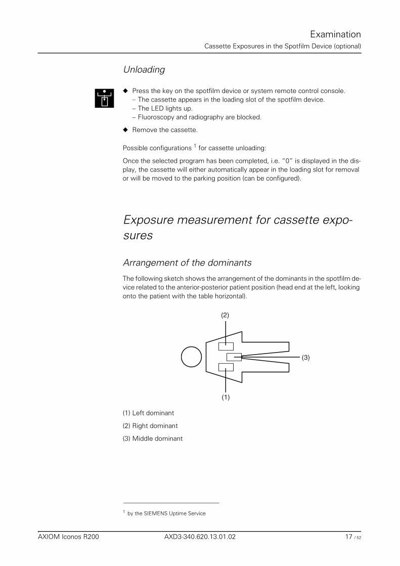
ExaminationCassette Exposures in the Spotfilm Device (optional)
Unloading
◆ Press the key on the spotfilm device or system remote control console.– The cassette appears in the loading slot of the spotfilm device.– The LED lights up.– Fluoroscopy and radiography are blocked.
◆ Remove the cassette.
Possible configurations 1 for cassette unloading:
Once the selected program has been completed, i.e. “0” is displayed in the dis-play, the cassette will either automatically appear in the loading slot for removal or will be moved to the parking position (can be configured).
Exposure measurement for cassette expo-sures
Arrangement of the dominants
The following sketch shows the arrangement of the dominants in the spotfilm de-vice related to the anterior-posterior patient position (head end at the left, looking onto the patient with the table horizontal).
(1) Left dominant
(2) Right dominant
(3) Middle dominant
1 by the SIEMENS Uptime Service
(1)
(2)
(3)
AXIOM Iconos R200 AXD3-340.620.13.01.02 17 / 52
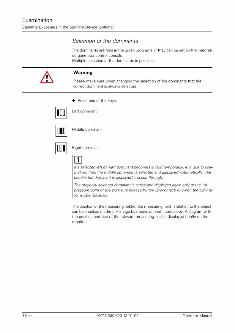
ExaminationCassette Exposures in the Spotfilm Device (optional)
Selection of the dominants
The dominants are filed in the organ programs or they can be set on the integrat-ed generator control console.Multiple selection of the dominants is possible.
◆ Press one of the keys.
Left dominant
Middle dominant
Right dominant
The position of the measuring field/of the measuring field in relation to the object can be checked on the LIH image by means of brief fluoroscopy. A diagram with the position and size of the relevant measuring field is displayed briefly on the monitor.
Warning
Please make sure when changing the selection of the dominants that the correct dominant is always selected.
If a selected left or right dominant becomes invalid temporarily, e.g. due to colli-mation, then the middle dominant is selected and displayed automatically. The deselected dominant is displayed crossed through.
The originally selected dominant is active and displayed again only at the 1st pressure point of the exposure release button (precontact) or when the collima-tor is opened again.
18 / 52 AXD3-340.620.13.01.02 Operator Manual
ExaminationCassette Exposures in the Spotfilm Device (optional)
Releasing the exposure❏ Release the exposure with the exposure release button in the system remote
control console or via the foot switch in the control room, or table-side (op-tion). The foot switch has no precontact.
❏ The signal lamps for radiation must light up briefly.
Organ programsAll parameters necessary for the exposure are stored in organ programs.
➩ Refer to the POLYDOROS SX register for further details on the organ programs and their programming.
Single exposures / serialography
Single exposure
Single exposure selected: the LED does not light up
◆ Select a suitable segmentation program. Possible selection:– Full format– Segmentation 2 on 1 / 3 on 1 / 4 on 1
If you now release the exposure, you receive one single exposure per exposure release.
Warning
If these radiation ON indicators light up although no switch has been actuated and the current fluoroscopic image cannot temporarily be seen on the monitor:
◆ Switch the system off immediately!
◆ Notify the SIEMENS Uptime Service.
◆ Discontinue operation of the system.
AXIOM Iconos R200 AXD3-340.620.13.01.02 19 / 52
ExaminationCassette Exposures in the Spotfilm Device (optional)
Serialography
Serialography selected: the LED lights up
◆ Select a segmentation program. – Segmentation 2 on 1 / 3 on 1 / 4 on 1
If you now release the series and keep the exposure release button pressed, you obtain an exposure series.
Bucky modeUse only the light localizer and the operating elements of the primary collimator for collimation.
Do not release fluoroscopy, otherwise Bucky mode is deselected.
◆ Press this key. – Spotfilm device exposure technique is selected: the LED lights up
◆ Press this key. – Bucky mode is selected: the LED lights up
◆ Insert a cassette and select a segmentation program.
Spotfilming without tomography
◆ Press this key. – Spotfilm device exposure technique is selected: the LED lights up
◆ Select semi or fully automatic mode.
◆ Insert a cassette and select a segmentation program.
◆ Select single exposure or serialography.
Serialography in combination with tomography is not possible!
20 / 52 AXD3-340.620.13.01.02 Operator Manual
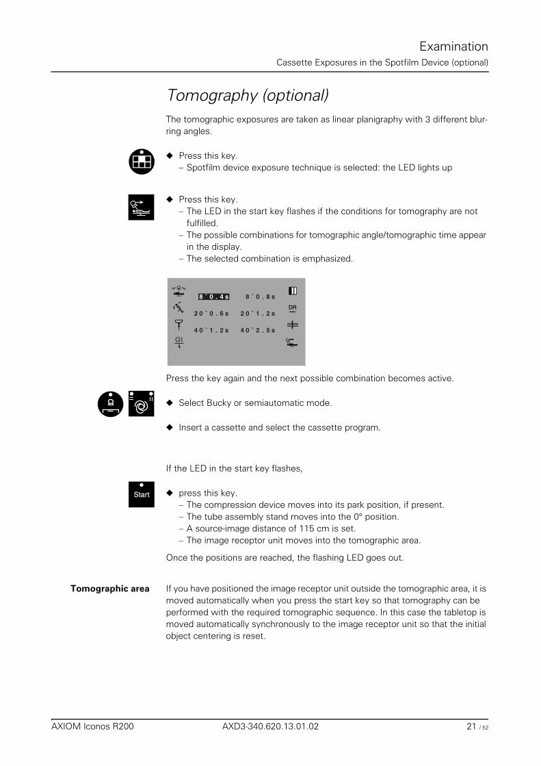
ExaminationCassette Exposures in the Spotfilm Device (optional)
Tomography (optional)The tomographic exposures are taken as linear planigraphy with 3 different blur-ring angles.
◆ Press this key. – Spotfilm device exposure technique is selected: the LED lights up
◆ Press this key. – The LED in the start key flashes if the conditions for tomography are not
fulfilled.– The possible combinations for tomographic angle/tomographic time appear
in the display.– The selected combination is emphasized.
Press the key again and the next possible combination becomes active.
◆ Select Bucky or semiautomatic mode.
◆ Insert a cassette and select the cassette program.
If the LED in the start key flashes,
◆ press this key.– The compression device moves into its park position, if present.– The tube assembly stand moves into the 0° position.– A source-image distance of 115 cm is set.– The image receptor unit moves into the tomographic area.
Once the positions are reached, the flashing LED goes out.
Tomographic area If you have positioned the image receptor unit outside the tomographic area, it is moved automatically when you press the start key so that tomography can be performed with the required tomographic sequence. In this case the tabletop is moved automatically synchronously to the image receptor unit so that the initial object centering is reset.
DR
s8.0˚8
2 0 ˚ 0 . 6 s
4 0 1 . 2 s˚
02 ˚ 1 . 2
4 0 ˚ 2 . 5 s
s
8 ˚ 0 . 4 s
Start
AXIOM Iconos R200 AXD3-340.620.13.01.02 21 / 52
ExaminationCassette Exposures in the Spotfilm Device (optional)
Tomographic sequence
◆ Press the exposure release button up to the first pressure point.– The tube assembly stand moves to the head-end tomography starting posi-
tion (at the left with the unit horizontal).
◆ Give the breathing command to the patient.
◆ Press the exposure release down fully and keep it pressed until the tube as-sembly stand stops in the foot-end position.– During the exposure the tube assembly stand moves towards the foot end
and automatically remains there following the exposure.
Prepare the next tomographic exposure:
◆ Set a new tomographic height.
◆ Press the exposure release button up to the first pressure point.– The tube assembly stand moves from the foot-end position towards the
head-end tomography starting position (at the left with the unit horizontal).
With the exposure release button pressed, the tube assembly stand moves back into the starting position.
22 / 52 AXD3-340.620.13.01.02 Operator Manual
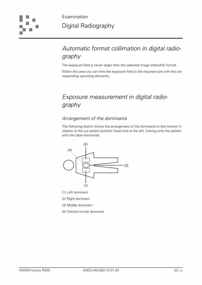
Examination
Digital Radiography
Automatic format collimation in digital radio-graphyThe exposure field is never larger than the selected image intensifier format.
Within this area you can limit the exposure field to the required size with the cor-responding operating elements.
Exposure measurement in digital radio-graphy
Arrangement of the dominants
The following sketch shows the arrangement of the dominants in the monitor in relation to the a-p patient position (head end at the left, looking onto the patient with the table horizontal).
(1) Left dominant
(2) Right dominant
(3) Middle dominant
(4) Central circular dominant
(1)
(2)
(4)
(3)
AXIOM Iconos R200 AXD3-340.620.13.01.02 23 / 52
ExaminationDigital Radiography
Selecting the dominants
The dominants are filed in the organ programs or can be set on the integrated generator control console.Multiple selection of the dominants is possible.
Exception: central circular dominant.
◆ Press one of the keys:
Left dominant
Middle dominant
Right dominant
Central circular dominant
When collimating under fluoroscopy, take care that the selected left or right dom-inant lies completely in the radiation field.Otherwise there will be overexposure because of the inappropriate acquisition of the measured exposure values.
The position of the measuring field/of the measuring field in relation to the object can be checked on the LIH image by means of brief fluoroscopy. A diagram with the position and size of the relevant measuring field is displayed briefly on the monitor.
Warning
Please make sure when changing the selection of the dominants that the cor-rect dominant is always selected.
If a selected left and/or right dominant becomes invalid temporarily, e.g. due to collimation, then the central circular dominant is selected and displayed automat-ically.
The originally selected dominant(s) will be active and displayed again when the collimator is opened again.
24 / 52 AXD3-340.620.13.01.02 Operator Manual
ExaminationDigital Radiography
Spotfilming without tomography
Selection
◆ Press this key. – Digital radiography is selected: the LED lights up
◆ At the integrated generator control console, select an organ program for– Single image or– Serialography or– DSA
Single image - serialography
Not possible in DSA.
The display is in the operating area of the live image monitor.
Changing selection
◆ If you press this key– the system switches over to single image in the “Serialography organ pro-
gram”– single image remains selected in the “Single image organ program”
Frame rate
Operation is on the infrared control of the FLUOROSPOT Compact.
◆ During a native series the programmed frrame rate can be rduced in a maxi-mum of 2 stages by pressing the button, if the corresponding ruductions have been programmed in the relevant organ program (see FLUOROSPOT Com-pact).
DRDR
The image intensifier format cannot be changed during an exposure series. Only the collimation is corrected on changing over to a larger zoom level.
A changed organ program for serialography remains retained only until you se-lect another / same organ program or switch the system off.
F/s
AXIOM Iconos R200 AXD3-340.620.13.01.02 25 / 52
ExaminationDigital Radiography
Releasing the exposure
❏ Release the exposure with the exposure release button in the system remote control console or via the foot switch in the control room, or table-side (op-tion).
❏ The radiation ON indicators must light up briefly during the exposure.
Radiation interruption If you let go of the exposure release button during radiation, the exposure is in-terrupted immediately in single exposure, in serialography the last exposure is still exposed correctly.
If a DSA series is interrupted before exposing the mask, then the first image is used as mask. The series is then displayed native.
Exposure end In single exposure only one image is exposed, even if the exposure release but-ton continues to be pressed.
In serialography, letting the exposure release button go, a full image memory or reaching the programmed maximum scene time ends the exposure series.
The DSA series is ended and the DSA image from the middle of the series is dis-played if you let the exposure release button go.
You start a new DSA exposure series by pressing the exposure release button again.
In DSA exposures The system switches automatically to subtraction after a predetermined number of images (e.g. 2).
The point in time at which the contrast medium should be injected must be se-lected depending on the examination.
Organ programs
All parameters necessary for the exposure are stored in organ programs.
➩ Refer to the FLUOROSPOT Compact and POLYDOROS SX operating instruc-tions for further details on the organ programs and their programming.
Warning
If these radiation ON indicators light up although no switch has been actuated and the current fluoroscopic image cannot be seen on the monitor:
◆ Switch the generator off immediately!
◆ Notify the SIEMENS Uptime Service.
◆ Discontinue operation of the system.
26 / 52 AXD3-340.620.13.01.02 Operator Manual
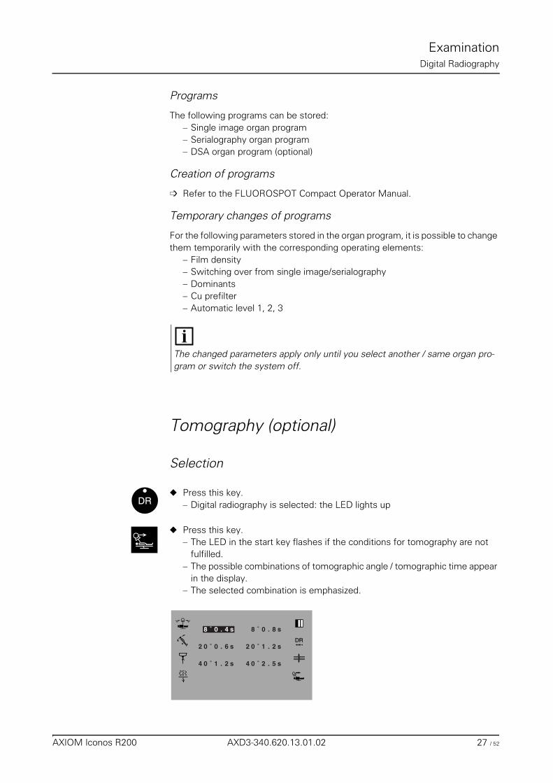
ExaminationDigital Radiography
Programs
The following programs can be stored:– Single image organ program– Serialography organ program– DSA organ program (optional)
Creation of programs
➩ Refer to the FLUOROSPOT Compact Operator Manual.
Temporary changes of programs
For the following parameters stored in the organ program, it is possible to change them temporarily with the corresponding operating elements:
– Film density– Switching over from single image/serialography– Dominants– Cu prefilter– Automatic level 1, 2, 3
Tomography (optional)
Selection
◆ Press this key. – Digital radiography is selected: the LED lights up
◆ Press this key. – The LED in the start key flashes if the conditions for tomography are not
fulfilled.– The possible combinations of tomographic angle / tomographic time appear
in the display.– The selected combination is emphasized.
The changed parameters apply only until you select another / same organ pro-gram or switch the system off.
DRDR
DR
s8.0˚8
2 0 ˚ 0 . 6 s
4 0 1 . 2 s˚
02 ˚ 1 . 2
4 0 ˚ 2 . 5 s
s
8 ˚ 0 . 4 s
AXIOM Iconos R200 AXD3-340.620.13.01.02 27 / 52
ExaminationDigital Radiography
Press the key again to activate the next possible combination.
If the LED in the start key flashes,
◆ press the key.– The compression device moves into park position, if present.– The tube assembly stand moves into the 0° position.– A source-image intensifier distance of 115 cm is set.– The image receptor unit moves into the tomographic area.
Once the positions are reached, the flashing LED goes out.
Tomographic area If you have positioned the image receptor unit outside the tomographic area, it is moved automatically when you press the start key so that tomography can be performed with the required tomographic sequence. In this case the tabletop is moved automatically synchronously to the image receptor unit.
Tomographic sequence
◆ Press the exposure release button up to the first pressure point.– The tube assembly stand moves to the head-end tomography starting posi-
tion (at the left with the unit horizontal).
◆ Give the breathing command to the patient.
◆ Press the exposure release button all the way down and hold pressed until the tube assembly stand stops.– During the exposure the tube assembly stand moves towards the foot end
and automatically remains there following the exposure.
Prepare the next tomographic exposure:
◆ Set a new tomographic height.
◆ Press the exposure release button up to the first pressure point.– The tube assembly stand moves from the foot-end position towards the
head-end tomography starting position (at the left with the unit horizontal).
Start
In the case of low-absorption objects with a water value below 10 cm (e.g. pe-diatrics, upper/lower extremities) either fluoroscopy must be performed before tomography or a Cu additional filter of at least 0,1 mm must be moved into the beam path. Otherwise exposures may be overexposed or interrupted and there-fore useless.
With the exposure release button pressed, the tube assembly stand moves back into the starting position.
28 / 52 AXD3-340.620.13.01.02 Operator Manual
ExaminationDigital Radiography
Releasing the exposure
❏ To release the exposure, actuate the exposure release button in the unit re-mote control console.
❏ The radiation ON indicators must light up during the exposure.
Radiation interruption If you let go of the exposure release button during radiation, the exposure is in-terrupted immediately and the tomographic movement is stopped.
Exposure end Letting go of the exposure release button or elapsing of the tomographic time ends the exposure.
Organ programs
All parameters necessary for the exposure are stored in organ programs.
➩ Refer to the FLUOROSPOT Compact and POLYDOROS SX operating instruc-tions for further details on the organ programs and their programming.
Programs
The following programs can be stored:– Tomography organ programs
Creation of programs
➩ Refer to the FLUOROSPOT Compact operating instructions.
Temporary changes of programs
For the following parameters stored in the organ program, it is possible to change them temporarily with the corresponding operating elements:
– Film density– Cu prefilter
Warning
If these radiation ON indicators light up although no switch has been actuated and the current fluoroscopic image cannot be seen on the monitor:
◆ Switch the generator off immediately!
◆ Notify the SIEMENS Uptime Service.
◆ Discontinue operation of the system.
The changed parameters apply only until you select another / same organ pro-gram or switch the system off.
AXIOM Iconos R200 AXD3-340.620.13.01.02 29 / 52
ExaminationDigital Radiography
PeriscanningSerial exposures of the contrast bolus during aortoarteriography with the patient at rest.
General
Periscanning is selected after the patient has been positioned, the catheter has been placed and the system settings for aorto-arteriography have been per-formed.Proceeding from the abdomen (starting position), the entire peripheral examina-tion area is scanned. The scan movement takes place with increasing movement speed of the X-ray system longitudinal displacement with finely graduated con-trollable adaptation of the speed to the contrast medium flow. The max. travel speed of the X-ray system is increased to 16 cm/s.
Selection
◆ Press this key.– Periscanning is selected: the LED lights up.
◆ Select an organ program for Periscanning.
Deselection
◆ Press this key or select another exposure system.– Periscanning is deselected.
You generate an organ program with image series for Periscanning in the Digital Radiography menu.
DRDR
The LEDs in the buttons for Periscanning and DR flash if the prerequisites for Periscanning are not met.
DRDR
30 / 52 AXD3-340.620.13.01.02 Operator Manual
ExaminationDigital Radiography
Releasing the exposure
❏ Release the exposure with the exposure release button on the system remote control console or via the foot switch in the control room, or table-side (op-tion).
❏ Radiation is released long as long as you continue to press the exposure re-lease button.
❏ The radiation ON indicators must light up.
Radiation interruption If you let go of the exposure release button during radiation, the exposure is in-terrupted immediately.
Exposure end Letting go of the exposure release button , a full image memory or reaching the programmed maximum scene time ends the exposure series.
Examination procedure
Preparation
◆ Prepare the digital imaging system
◆ Move the tube assembly into the 0° position
◆ Position the patient
◆ Set a nominal source-image intensifier distance of 115 cm or 150 cm
◆ Bring the X-ray system and tabletop into the intended starting position.
You must ensure that the travel range for the X-ray system is sufficient.
◆ Press this key.– The LED lights up: Periscanning is selected.– Serialography is selected.
Warning
If these radiation ON indicators light up although no switch has been actuated and the current fluoroscopic image cannot be seen on the monitor:
◆ Switch the system off immediately!
◆ Notify the SIEMENS Uptime Service.
◆ Discontinue operation of the system.
DRDR
The LEDs in the Periscanning and start keys flash if the conditions for exposure are not fulfilled.
AXIOM Iconos R200 AXD3-340.620.13.01.02 31 / 52
ExaminationDigital Radiography
If the LED in the start key flashes,
◆ press the key.– The compression device moves into park position, if present– Oblique setting moves into the 0° position
Once these positions are reached, the flashing LED goes out.
◆ Select an organ program for Periscanning
◆ Position the patient and set the following parameters with the corresponding operating elements:– Primary collimation (rectangular diaphragm)– Semitransparent wedge filters (if option is available)– Cu prefilter (preferably filed in the organ program)
Adapting thedominant
◆ Press one/several keys,– The dominant preset in the organ program is overwritten.
Prepare the injector ◆ Connect the injector plug to the electronics cabinet (only with radiation-syn-chronous injector release (option)).
◆ Set the injection data and switch to ready for injections.
Test run
The X-ray system stands in the starting position for the scanning process.
Start a test run without radiation.
◆ Switch the light localizer of the collimator on.
◆ Deflect the joystick up / down or the key to the left / right until the required examination area has been scanned.
◆ If necessary correct the starting position.
Start
Position the patient so that the region the vascular filling of which should be im-aged first is located in the central ray.
If a left / right dominant or both dominants are selected, the system switches over automatically to the central circular dominant if the preselected dominant is covered by the filters, since this would inevitably result in a faulty exposure.
32 / 52 AXD3-340.620.13.01.02 Operator Manual
ExaminationDigital Radiography
Scanning process
The X-ray system stands in the starting position for the scanning process.
◆ Press an exposure release button and keep it pressed up to the end of the ex-amination, i.e. until the scanning process is ended.
◆ Trigger the injection, automatically or manually
◆ Deflect the joystick up / down or press the key to the left / right until the entire examination area has been scanned.
◆ If necessary reduce the frame rate in a maximum of 2 steps, as filed in the organ program (saving dose and storage capacity).
End of the scene
◆ Let the exposure release button go.
Organ programs
All parameters necessary for the exposure are stored in organ programs.
➩ Refer to the FLUOROSPOT Compact Operator Manual and the POLYDOROS SX register for further details on the organ programs and their programming.
Creation of programs
➩ Refer to the FLUOROSPOT Compact Operator Manual.
Temporary changes of programs
For the following parameters stored in the organ program, it is possible to change them temporarily with the corresponding operating elements:
– Film density– Dominants– Cu prefilter– Automatic level 1, 2, 3
Follow the contrast medium flow on the monitor.Adapt the movement speed of the X-ray system to the contrast medium flow.
The exposure series is also ended if the image memory is full and the maximum scene time has been reached, independently of the position in which the system is located.
The changed parameters apply only until you select another / same organ pro-gram or switch the system off.
AXIOM Iconos R200 AXD3-340.620.13.01.02 33 / 52
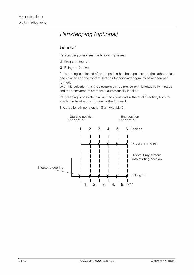
ExaminationDigital Radiography
Peristepping (optional)
General
Peristepping comprises the following phases:
❏ Programming run
❏ Filling run (native)
Peristepping is selected after the patient has been positioned, the catheter has been placed and the system settings for aorto-arteriography have been per-formed.With this selection the X-ray system can be moved only longitudinally in steps and the transverse movement is automatically blocked.
Peristepping is possible in all unit positions and in the axial direction, both to-wards the head end and towards the foot end.
The step length per step is 18 cm with I.I.40.
1. 2. 3. 4. 5.
1. 2. 3. 4. 5. 6.
Starting position X-ray system
End position X-ray system
Position
Step
Programming run
Filling run
Injector triggering
Move X-ray systeminto starting position
34 / 52 AXD3-340.620.13.01.02 Operator Manual
ExaminationDigital Radiography
Programming run
Proceeding from the abdomen (starting position), the primary collimators, semi-transparent wedge filters and dominant, if required, are set step by step (up to the last position).You must deflect the joystick or press the key for “X-ray system longitudinal movement” in the movement direction for each step as long as the next step po-sition is reached. Once the next step position is reached, the X-ray system stops automatically and the corresponding position number appears on the remote con-trol console.The last set collimator positions, filter positions and dominants are stored auto-matically assigned to each step position.A maximum of 6 positions (5 steps) is possible.After the programming run is completed, the X-ray system must be moved back to the starting position (abdomen) (automatic stop).
Filling run
Initiate the individual steps of the X-ray system using the joystick or the key for “X-ray system longitudinal movement” corresponding to the contrast medium flow with monitoring on the live image monitor.
Selection
◆ Press this key.– Peristepping is selected: the LED lights up.
Deselection
◆ Press this key or select another exposure system.– Peristepping is deselected.
DRDR
There is no automatic deselection of Peristepping after the end of the scene.
DRDR
AXIOM Iconos R200 AXD3-340.620.13.01.02 35 / 52
ExaminationDigital Radiography
Releasing an exposure
❏ Release the exposure with the exposure release button on the system remote control console or via the foot switch in the control room, or table-side (op-tion).
❏ Radiation is released as long as you continue to press the exposure release button.
❏ The radiation ON indicators must light up.
Radiation interruption If you let go of the exposure release button during radiation, the exposureis inter-rupted immediately.
Exposure end Letting the exposure release button go, a full image memory or reaching the max-imum scene time ends the exposure series including contrast medium injection.
The scene time refers to the set maximum frame rate. A reduction of the frame rate leads to a corresponding lengthening of the scene time.
Examination procedure
Preparation
◆ Prepare the digital imaging system
◆ Move the tube assembly into the 0° position
◆ Transfer and position the patient
◆ Move the X-ray system and tabletop into the intended starting position
◆ Press this key.– Peristepping is selected: the LED lights up.– The starting position is now defined– The display of the current position and the maximum exposure positions,
e.g. 1/4 appears on the display in the remote control console.– I.I. full format is selected– Transverse table travel is blocked
Warning
If these radiation ON indicators light up although no switch has been actuated and the current fluoroscopic image cannot be seen on the monitor:
◆ Switch the system off immediately!
◆ Notify the SIEMENS Uptime Service.
◆ Discontinue operation of the system.
DRDR
36 / 52 AXD3-340.620.13.01.02 Operator Manual
ExaminationDigital Radiography
If the LED in the start key flashes,
◆ press the key.– The compression device moves into park position, if present– Oblique setting moves into 0° position– A source-image intensifier distance of 115 cm is set
Once these positions are reached, the flashing LED goes out.
◆ Select an organ program for Peristepping.
◆ Set the following parameters with the corresponding operating elements:– Primary rectangular collimators– Cu prefilter– Semitransparent wedge filters
Adapting thedominant
◆ Press one/several keys– The dominant preset in the organ program is overwritten.
Prepare the injector ◆ Connect the injector plug to the electronics cabinet (only with radiation-syn-chronous injector release (option)).
◆ Set the injection data and switch to ready for injections.
The LEDs in the Peristepping and start keys flash if the conditions for exposure are not fulfilled.
Start
Zoom formats cannot be selected. The I.I. full format of 40 cm is always select-ed.The primary collimation is not set automatically to the full format, but must be adapted according to the object.
If a left / right dominant or both dominants are selected, the system switches over automatically to the central circular dominant if the preselected dominant is covered by the filters, since this would inevitably result in a faulty exposure.
AXIOM Iconos R200 AXD3-340.620.13.01.02 37 / 52
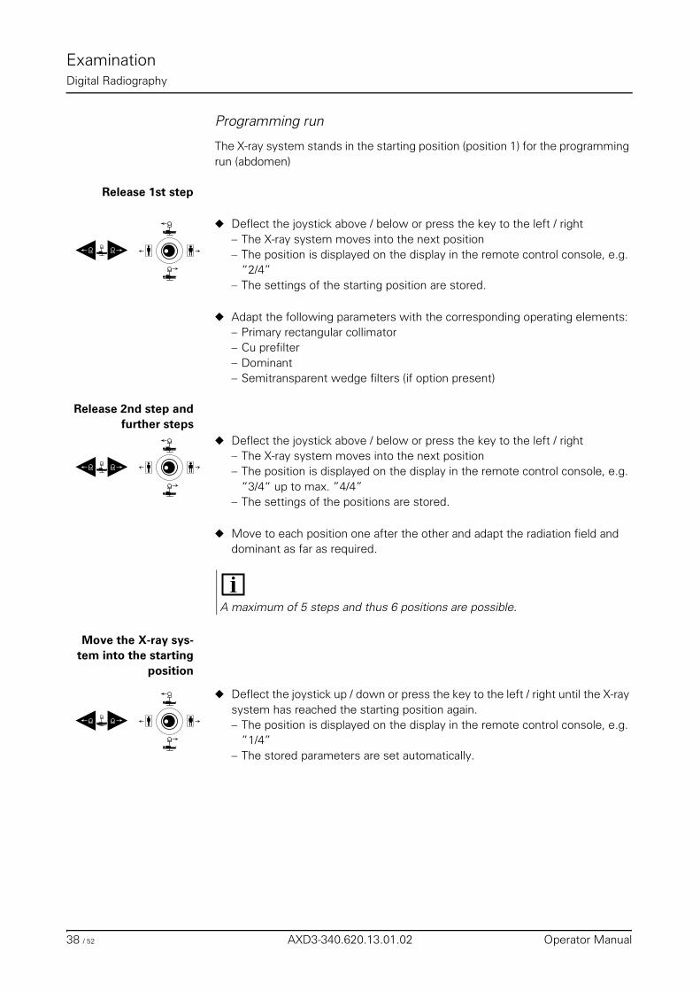
ExaminationDigital Radiography
Programming run
The X-ray system stands in the starting position (position 1) for the programming run (abdomen)
Release 1st step
◆ Deflect the joystick above / below or press the key to the left / right– The X-ray system moves into the next position– The position is displayed on the display in the remote control console, e.g.
“2/4” – The settings of the starting position are stored.
◆ Adapt the following parameters with the corresponding operating elements:– Primary rectangular collimator– Cu prefilter– Dominant– Semitransparent wedge filters (if option present)
Release 2nd step andfurther steps
◆ Deflect the joystick above / below or press the key to the left / right– The X-ray system moves into the next position– The position is displayed on the display in the remote control console, e.g.
“3/4“ up to max. ”4/4”– The settings of the positions are stored.
◆ Move to each position one after the other and adapt the radiation field and dominant as far as required.
Move the X-ray sys-tem into the starting
position
◆ Deflect the joystick up / down or press the key to the left / right until the X-ray system has reached the starting position again.– The position is displayed on the display in the remote control console, e.g.
”1/4” – The stored parameters are set automatically.
A maximum of 5 steps and thus 6 positions are possible.
38 / 52 AXD3-340.620.13.01.02 Operator Manual
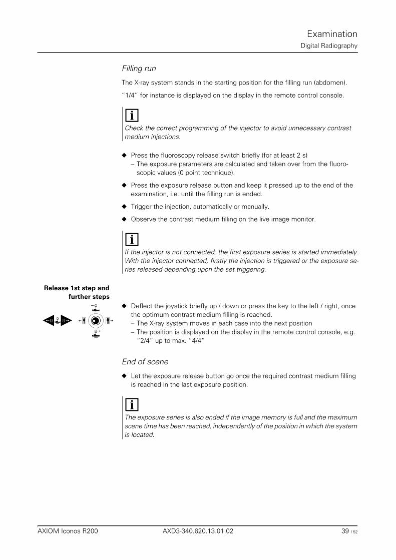
ExaminationDigital Radiography
Filling run
The X-ray system stands in the starting position for the filling run (abdomen).
“1/4” for instance is displayed on the display in the remote control console.
◆ Press the fluoroscopy release switch briefly (for at least 2 s)– The exposure parameters are calculated and taken over from the fluoro-
scopic values (0 point technique).
◆ Press the exposure release button and keep it pressed up to the end of the examination, i.e. until the filling run is ended.
◆ Trigger the injection, automatically or manually.
◆ Observe the contrast medium filling on the live image monitor.
Release 1st step andfurther steps
◆ Deflect the joystick briefly up / down or press the key to the left / right, once the optimum contrast medium filling is reached.– The X-ray system moves in each case into the next position– The position is displayed on the display in the remote control console, e.g.
“2/4” up to max. “4/4”
End of scene
◆ Let the exposure release button go once the required contrast medium filling is reached in the last exposure position.
Check the correct programming of the injector to avoid unnecessary contrast medium injections.
If the injector is not connected, the first exposure series is started immediately.With the injector connected, firstly the injection is triggered or the exposure se-ries released depending upon the set triggering.
The exposure series is also ended if the image memory is full and the maximum scene time has been reached, independently of the position in which the system is located.
AXIOM Iconos R200 AXD3-340.620.13.01.02 39 / 52
ExaminationDigital Radiography
Organ programs
All parameters necessary for the exposure are stored in organ programs.
➩ Refer to the FLUOROSPOT Compact Operator Manual and the POLYDOROS SX register for further details on the organ programs and their programming.
Creation of programs
➩ Refer to the FLUOROSPOT Compact Operator Manual.
Temporary changes of programs
For the following parameters stored in the organ program, it is possible to change them temporarily with the corresponding operating elements:
– Dominants
DR-Scanning (optional)
General
To display large objects, a series of displayed images is combined to give a large-format image in the image processor of the workstation.
The entire exposure area is moved over continuously with the image receptor proceeding from the starting position (not in Peristepping).
After the acquisition the images are sent from the imaging system to the LE-ONARDO workstation for processing (e.g. image reconstruction).
Depending on the examination, there are 2 types of acquisition:
❏ DR scanning for – images of the spine– orthopedic longleg images– abdominal survey images
❏ Peristepping for survey images of the peripheral vessels
The changed parameters apply only until you select another / same organ pro-gram or switch the system off.
Generate an organ program for the scanning technique in the series image menu.
40 / 52 AXD3-340.620.13.01.02 Operator Manual
ExaminationDigital Radiography
Selection
◆ Press this key.
◆ Press this key.– DR scanning is selected.– The display shows 3 scanning programs with 2 directions each.
◆ Select an organ program for DR scanning at the integrated generator console.
Deselection
◆ Press this key or select a different exposure system.– DR scanning is deselected.
Image transfer
◆ Send the images from the imaging system to the LEONARDO workstation us-ing the "DICOM Send” function.
Releasing an exposure
❏ Release the exposure with the exposure release button in the system remote control console or via the footswitch in the control room, or table-side (option).
❏ Radiation is released as long as you continue to press the exposure release button.
❏ The signal lamps for radiation must light up.
Radiation interruption If you let go of the exposure release button during radiation, the exposure is in-terrupted immediately.
Exposure end Letting go of the exposure release button, a full image memory or reaching the maximum scene time ends the exposure series.
DRDR
DRDR
Warning
If these radiation ON indicators light up although no switch has been actuated and the current fluoroscopic image cannot be seen on the monitor:
◆ Switch the system off immediately!
◆ Notify SIEMENS Uptime Service.
◆ Discontinue operation of the system.
AXIOM Iconos R200 AXD3-340.620.13.01.02 41 / 52
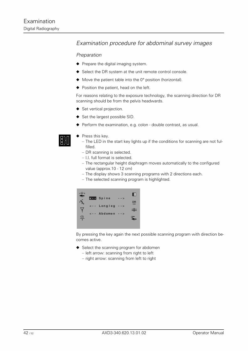
ExaminationDigital Radiography
Examination procedure for abdominal survey images
Preparation
◆ Prepare the digital imaging system.
◆ Select the DR system at the unit remote control console.
◆ Move the patient table into the 0° position (horizontal).
◆ Position the patient, head on the left.
For reasons relating to the exposure technology, the scanning direction for DR scanning should be from the pelvis headwards.
◆ Set vertical projection.
◆ Set the largest possible SID.
◆ Perform the examination, e.g. colon - double contrast, as usual.
◆ Press this key.– The LED in the start key lights up if the conditions for scanning are not ful-
filled.– DR scanning is selected.– I.I. full format is selected.– The rectangular height diaphragm moves automatically to the configured
value (approx.10 - 12 cm)– The display shows 3 scanning programs with 2 directions each.– The selected scanning program is highlighted.
By pressing the key again the next possible scanning program with direction be-comes active.
◆ Select the scanning program for abdomen– left arrow: scanning from right to left– right arrow: scanning from left to right
DR
L n
S ip n e< - -
gelg - - >o< - -
< - - A b d ome n - - >
- - >
42 / 52 AXD3-340.620.13.01.02 Operator Manual
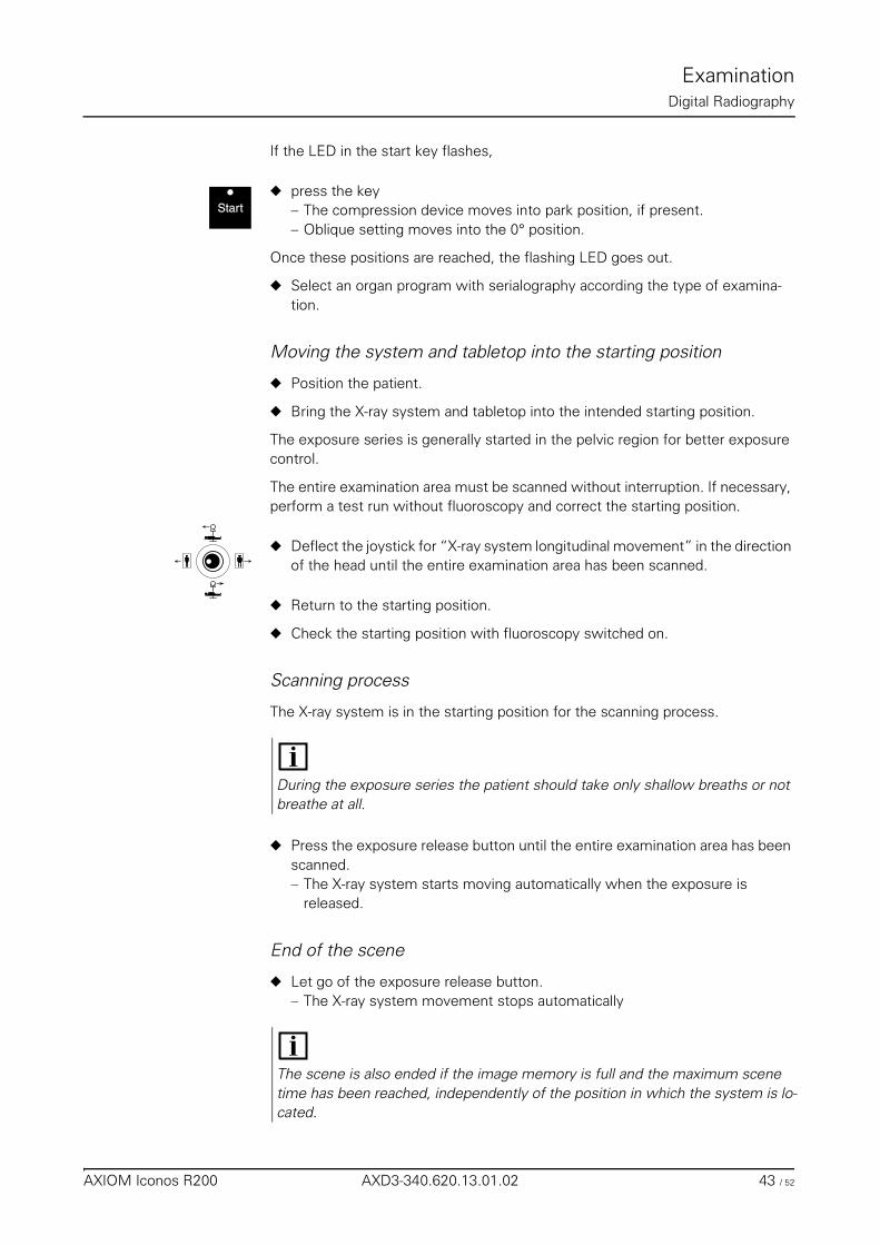
ExaminationDigital Radiography
If the LED in the start key flashes,
◆ press the key– The compression device moves into park position, if present.– Oblique setting moves into the 0° position.
Once these positions are reached, the flashing LED goes out.
◆ Select an organ program with serialography according the type of examina-tion.
Moving the system and tabletop into the starting position
◆ Position the patient.
◆ Bring the X-ray system and tabletop into the intended starting position.
The exposure series is generally started in the pelvic region for better exposure control.
The entire examination area must be scanned without interruption. If necessary, perform a test run without fluoroscopy and correct the starting position.
◆ Deflect the joystick for “X-ray system longitudinal movement” in the direction of the head until the entire examination area has been scanned.
◆ Return to the starting position.
◆ Check the starting position with fluoroscopy switched on.
Scanning process
The X-ray system is in the starting position for the scanning process.
◆ Press the exposure release button until the entire examination area has been scanned.– The X-ray system starts moving automatically when the exposure is
released.
End of the scene
◆ Let go of the exposure release button.– The X-ray system movement stops automatically
Start
During the exposure series the patient should take only shallow breaths or not breathe at all.
The scene is also ended if the image memory is full and the maximum scene time has been reached, independently of the position in which the system is lo-cated.
AXIOM Iconos R200 AXD3-340.620.13.01.02 43 / 52
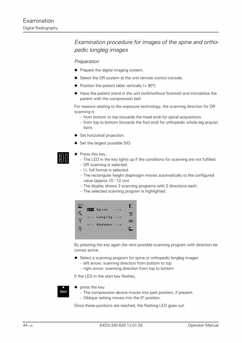
ExaminationDigital Radiography
Examination procedure for images of the spine and ortho-pedic longleg images
Preparation
◆ Prepare the digital imaging system.
◆ Select the DR system at the unit remote control console.
◆ Position the patient table vertically (+ 90°).
◆ Have the patient stand in the unit (with/without footrest) and immobilize the patient with the compression belt.
For reasons relating to the exposure technology, the scanning direction for DR scanning is
– from bottom to top (towards the head end) for spinal acquisitions– from top to bottom (towards the foot end) for orthopedic whole leg acquisi-
tions
◆ Set horizontal projection.
◆ Set the largest possible SID.
◆ Press this key.– The LED in the key lights up if the conditions for scanning are not fulfilled.– DR scanning is selected.– I.I. full format is selected.– The rectangular height diaphragm moves automatically to the configured
value (approx.10 - 12 cm)– The display shows 3 scanning programs with 2 directions each.– The selected scanning program is highlighted.
By pressing the key again the next possible scanning program with direction be-comes active.
◆ Select a scanning program for spine or orthopedic longleg images– left arrow: scanning direction from bottom to top– right arrow: scanning direction from top to bottom
If the LED in the start key flashes,
◆ press the key.– The compression device moves into park position, if present.– Oblique setting moves into the 0° position.
Once these positions are reached, the flashing LED goes out.
DR
L n
S ip n e< - -
gelg - - >o< - -
< - - A b d ome n - - >
- - >
Start
44 / 52 AXD3-340.620.13.01.02 Operator Manual
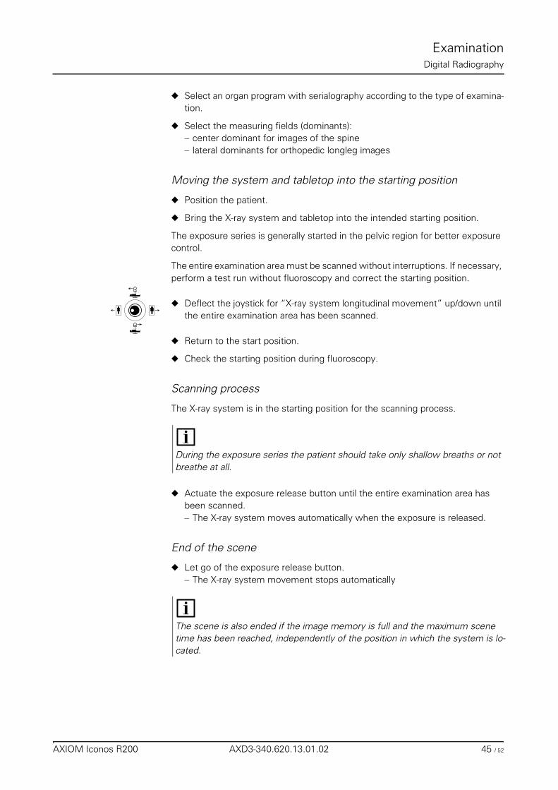
ExaminationDigital Radiography
◆ Select an organ program with serialography according to the type of examina-tion.
◆ Select the measuring fields (dominants):– center dominant for images of the spine– lateral dominants for orthopedic longleg images
Moving the system and tabletop into the starting position
◆ Position the patient.
◆ Bring the X-ray system and tabletop into the intended starting position.
The exposure series is generally started in the pelvic region for better exposure control.
The entire examination area must be scanned without interruptions. If necessary, perform a test run without fluoroscopy and correct the starting position.
◆ Deflect the joystick for “X-ray system longitudinal movement” up/down until the entire examination area has been scanned.
◆ Return to the start position.
◆ Check the starting position during fluoroscopy.
Scanning process
The X-ray system is in the starting position for the scanning process.
◆ Actuate the exposure release button until the entire examination area has been scanned. – The X-ray system moves automatically when the exposure is released.
End of the scene
◆ Let go of the exposure release button.– The X-ray system movement stops automatically
During the exposure series the patient should take only shallow breaths or not breathe at all.
The scene is also ended if the image memory is full and the maximum scene time has been reached, independently of the position in which the system is lo-cated.
AXIOM Iconos R200 AXD3-340.620.13.01.02 45 / 52
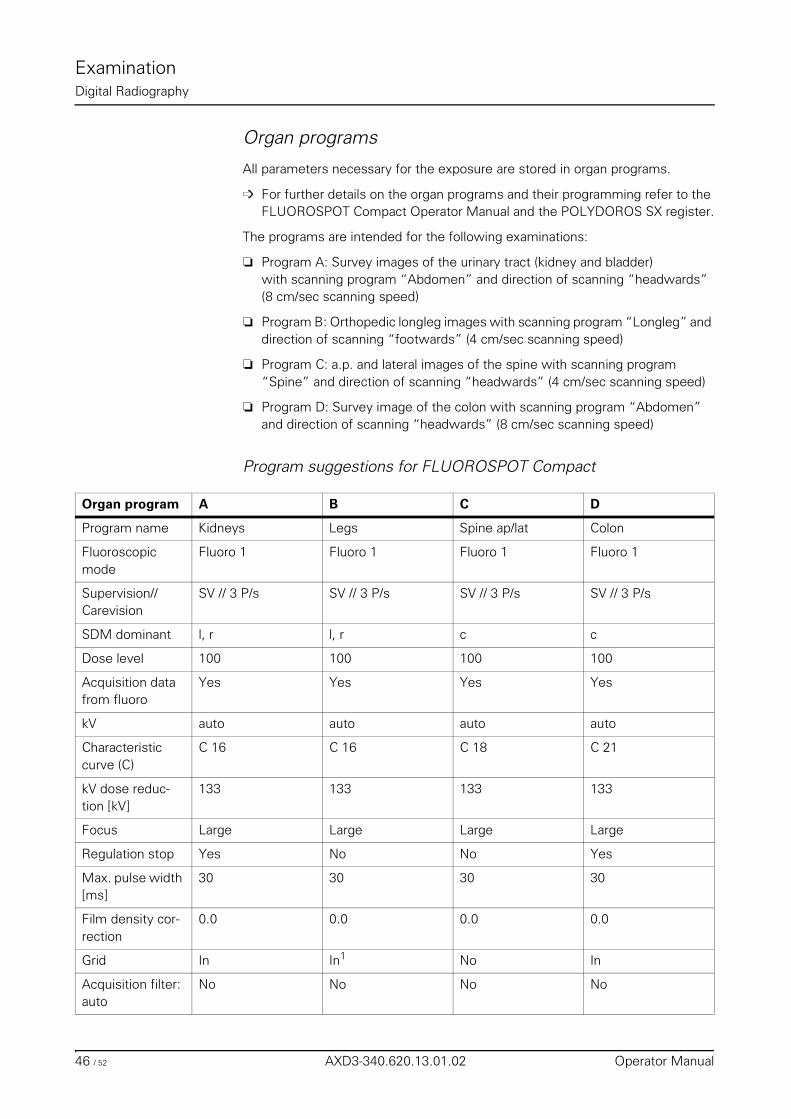
ExaminationDigital Radiography
Organ programs
All parameters necessary for the exposure are stored in organ programs.
➩ For further details on the organ programs and their programming refer to the FLUOROSPOT Compact Operator Manual and the POLYDOROS SX register.
The programs are intended for the following examinations:
❏ Program A: Survey images of the urinary tract (kidney and bladder)with scanning program “Abdomen” and direction of scanning “headwards” (8 cm/sec scanning speed)
❏ Program B: Orthopedic longleg images with scanning program “Longleg” and direction of scanning “footwards” (4 cm/sec scanning speed)
❏ Program C: a.p. and lateral images of the spine with scanning program “Spine” and direction of scanning “headwards” (4 cm/sec scanning speed)
❏ Program D: Survey image of the colon with scanning program “Abdomen” and direction of scanning “headwards” (8 cm/sec scanning speed)
Program suggestions for FLUOROSPOT Compact
Organ program A B C D
Program name Kidneys Legs Spine ap/lat Colon
Fluoroscopic mode
Fluoro 1 Fluoro 1 Fluoro 1 Fluoro 1
Supervision//Carevision
SV // 3 P/s SV // 3 P/s SV // 3 P/s SV // 3 P/s
SDM dominant l, r l, r c c
Dose level 100 100 100 100
Acquisition data from fluoro
Yes Yes Yes Yes
kV auto auto auto auto
Characteristic curve (C)
C 16 C 16 C 18 C 21
kV dose reduc-tion [kV]
133 133 133 133
Focus Large Large Large Large
Regulation stop Yes No No Yes
Max. pulse width [ms]
30 30 30 30
Film density cor-rection
0.0 0.0 0.0 0.0
Grid In In1 No In
Acquisition filter: auto
No No No No
46 / 52 AXD3-340.620.13.01.02 Operator Manual
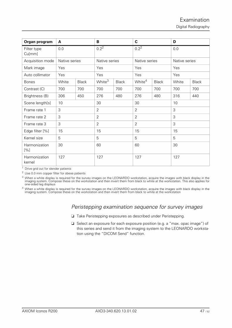
ExaminationDigital Radiography
Peristepping examination sequence for survey images
❏ Take Peristepping exposures as described under Peristepping.
❏ Select an exposure for each exposure position (e.g. a “max. opac image”) of this series and send it from the imaging system to the LEONARDO worksta-tion using the “DICOM Send” function.
Filter type Cu[mm]
0.0 0.22 0.22 0.0
Acquisition mode Native series Native series Native series Native series
Mark image Yes Yes Yes Yes
Auto collimator Yes Yes Yes Yes
Bones White Black White3 Black White4 Black White Black
Contrast (C) 700 700 700 700 700 700 700 700
Brightness (B) 306 450 276 480 276 480 316 440
Scene length[s] 10 30 30 10
Frame rate 1 3 2 2 3
Frame rate 2 3 2 2 3
Frame rate 3 3 2 2 3
Edge filter [%] 15 15 15 15
Kernel size 5 5 5 5
Harmonization [%]
30 60 60 30
Harmonization kernel
127 127 127 127
1 Drive grid out for slender patients2 Use 0.0 mm copper filter for obese patients3 When a white display is required for the survey images on the LEONARDO workstation, acquire the images with black display in the
imaging system. Compose these on the workstation and then invert them from black to white at the workstation. This also applies forone-sided leg displays
4 When a white display is required for the survey images on the LEONARDO workstation, acquire the images with black display in theimaging system. Compose these on the workstation and then invert them from black to white at the workstation
Organ program A B C D
AXIOM Iconos R200 AXD3-340.620.13.01.02 47 / 52

ExaminationDigital Radiography
48 / 52 AXD3-340.620.13.01.02 Operator Manual
Examination
Free Cassette Exposure
Collimation on exposure❏ The automatic format collimation of the system is not effective if you have se-
lected ”tabletop cassette exposure or free mode”, or if you have turned the tube assembly into a position outside 0°.– You can set the exposure format freely.– The limits of the maximum radiation field are determined by the mecha-
nism of the primary collimator.– The collimator does not react to a change of the SID.– The digital display field of the primary collimator shows ”Manual”.
Selecting the exposure technique
Tabletop cassette exposure or free mode
◆ Press this key– The LED lights up
With tabletop cassette exposure or the tube assembly swivelled out, the sys-tem automatically switches over to “Free mode / tabletop exposure”. The au-tomatic format collimation system is disabled.
AXIOM Iconos R200 AXD3-340.620.13.01.02 49 / 52
ExaminationFree Cassette Exposure
Releasing an exposure❏ To release the exposure, actuate the exposure release button on the genera-
tor ON/OFF console.
❏ Before every exposure release check:– the format limitation with the aid of the light localizer on the collimator– the set SID with the tape measure on the collimator– the central ray on cassette center with the aid of the laser line light localizer
on the collimator.
❏ The radiation ON indicators must light up.
For safety reasons, radiation cannot be released from the system control con-sole or the footswitch in this mode.
Warning
If these radiation indicators light up although no switch has been actuated :
◆ Switch the system off immediately!
◆ Notify the SIEMENS Uptime Service.
◆ Discontinue operation of the system.
50 / 52 AXD3-340.620.13.01.02 Operator Manual
Examination
Cassette exposures with wall stand
Collimation during exposureWith the table vertical and 180° rotation of the tube assembly, the automatic for-mat collimation of the system switches over automatically
❏ to the “ACSS Mode” (with automatic format collimation) if using a wall stand with automatic format collimation (option)
❏ to the “Manual Mode” (without automatic format collimation) if using a wall stand without automatic format collimation
Selecting the exposure technique◆ Select the “wall stand” system at the integrated generator control console
◆ Set the table to a vertical position
◆ Set the tube assembly to a source-image distance of 115 cm or 150 cm.
◆ Turn the tube assembly horizontally onto the wall stand
◆ Place the cassette in the Bucky
◆ Position the patient in front of the wall stand
◆ Set the wall stand to the object height
◆ Adjust the tube assembly to the object using the full-field light localizer and positioning laser
◆ Collimate in relation to the object
with automatic formatcollimation(option)
The radiation field is automatically set to the cassette format and can then be col-limated as small as required in relation to the object.
without automatic for-mat collimation
There is no limitation of the radiation field and collimation must be performed in relation to the object using the full-field light localizer.
◆ Select measuring field
AXIOM Iconos R200 AXD3-340.620.13.01.02 51 / 52
ExaminationCassette exposures with wall stand
Releasing the exposure❏ To release the exposure, actuate the exposure release button on the genera-
tor ON/OFF console.
❏ Before each exposure release check:– the collimation with the aid of the light localizer on the multileaf collimator– the set SID with the tape measure on the multileaf collimator– that if the dominants are changed the correct dominant is always selected– the central ray onto the cassette center with the aid of the laser line light
localizer on the multileaf collimator
❏ The signal lamps for radiation ON must light up.
For safety reasons, radiation cannot be released from the system control con-sole or the footswitch in this mode.
Warning
If these radiation indicators light up although no switch has been actuated:
◆ Switch the system off immediately!
◆ Notify SIEMENS Uptime Service.
◆ Do not start the system up again.
52 / 52 AXD3-340.620.13.01.02 Operator Manual
POLYDOROS SX 65/80Overall Table of Contents
Operator Manual
POLYDOROS SX 65/80
Chapter: Integrated Control Console
Application .......................................................................................................................... 3
Configuration ...................................................................................................................... 3Basic version .................................................................................................................. 3Options ......................................................................................................................... 3
Overview of the controls and displays ............................................................................... 4Menu ........................................................................................................................... 4
Data menu ............................................................................................................ 5Program menu ....................................................................................................... 8
Explanation of displays and controls ................................................................................... 9Selection of the controls ................................................................................................... 9Normal/inverted display of the controls ................................................................................ 9Functions of the +/- controls .............................................................................................. 9Changing the focal spot and tube load ................................................................................. 9Selecting the measuring field (dominant) ............................................................................. 9Measuring field (dominant) display .................................................................................... 10Display of the exposure data ........................................................................................... 10
Messages ......................................................................................................................... 10General error messages ................................................................................................. 10
Tube load computer ......................................................................................................... 10General ....................................................................................................................... 10Pause time indication ..................................................................................................... 11Load data indication ....................................................................................................... 11
Functional and safety checks ........................................................................................... 12Daily checks ................................................................................................................. 12
After switching on ................................................................................................ 12During the examination .......................................................................................... 12
Monthly checks ............................................................................................................ 12Legally required checks .................................................................................................. 12Maintenance intervals .................................................................................................... 12
Fluoroscopy ...................................................................................................................... 13Releasing fluoroscopy .................................................................................................... 13
AXIOM Iconos R200 AXD3-340.620.13.01.02 1 / 36
POLYDOROS SX 65/80Overall Table of Contents
Selecting the fluoroscopic mode ...................................................................................... 13Fluoroscopy with automatic control .......................................................................... 13High-contrast fluoroscopy1 ..................................................................................... 13
Fluoroscopic data .......................................................................................................... 13Display of the kV and mA values .............................................................................. 13Display of the fluoroscopic time .............................................................................. 13Display of the dose area product ............................................................................. 13Resetting the fluoroscopic data1 ............................................................................. 13
Fluoroscopic characteristic curves .................................................................................... 14Fluoroscopic time limit ................................................................................................... 15
Exposure ........................................................................................................................... 15Exposure release .......................................................................................................... 15Automatic exposure system “0-point technique” ................................................................ 16
General .............................................................................................................. 16Programmed characteristic curves ........................................................................... 16
Selecting direct exposure technique ................................................................................. 21Select 0-point technique ........................................................................................ 21Select 1-point technique ........................................................................................ 22Select 2-point technique ........................................................................................ 23Select 3-point technique ........................................................................................ 24Select 3-point technique with IONTOMAT ................................................................. 25Select mAs tomography ........................................................................................ 26Select tomography with Plani-IONTOMAT ................................................................. 27Select tomography with Plani-IONTOMAT and mAs preselection ................................... 28
Select indirect exposure technique ................................................................................... 29Select DR 0-point technique ................................................................................... 29Select DR 1-point technique ................................................................................... 30Select DR tomography with Plani-IONTOMAT ............................................................ 31Select DSA constant time ...................................................................................... 32
Organ programs ................................................................................................................ 32Selecting an organ program ............................................................................................. 33Organ program data indication ......................................................................................... 33Editing organ program data ............................................................................................. 33
Temporary change ................................................................................................ 33Permanent storage ............................................................................................... 33Editing new organ program names ........................................................................... 34
2 / 36 AXD3-340.620.13.01.02 Operator Manual
POLYDOROS SX 65/80
Integrated Control Console
ApplicationPOLYDOROS SX 65/80 is a high-frequency X-ray generator for all procedures in general diagnostic radiology.
The combination of microprocessor control and high-frequency converter tech-nology ensures good X-ray images due to the high accuracy of the exposure data.
Configuration
Basic version
❏ IONTOMAT PN automatic exposure control
❏ IONTOMAT PN automatic exposure control for tomography
❏ Tomographic device connection
❏ Polymatic incl. 0-point technique
❏ Programming unit for organ programs
❏ RS 232 printer connection
❏ Tube load computer
Options
❏ Connection for 3rd tube assembly
AXIOM Iconos R200 AXD3-340.620.13.01.02 3 / 36

POLYDOROS SX 65/80Integrated Control Console
Overview of the controls and displays
Integrated generator control console on the FLUOROSPOT Compact screen
Menu
On the basis of the selected program or operating mode the permissible operat-ing functions and operating data are indicated in menus on the integrated gener-ator control console.
Various menus are available depending on the program or operating mode:
❏ Data menu– Displays and controls for radiographic parameters
❏ Program menu– Display of organ programs
4 / 36 AXD3-340.620.13.01.02 Operator Manual
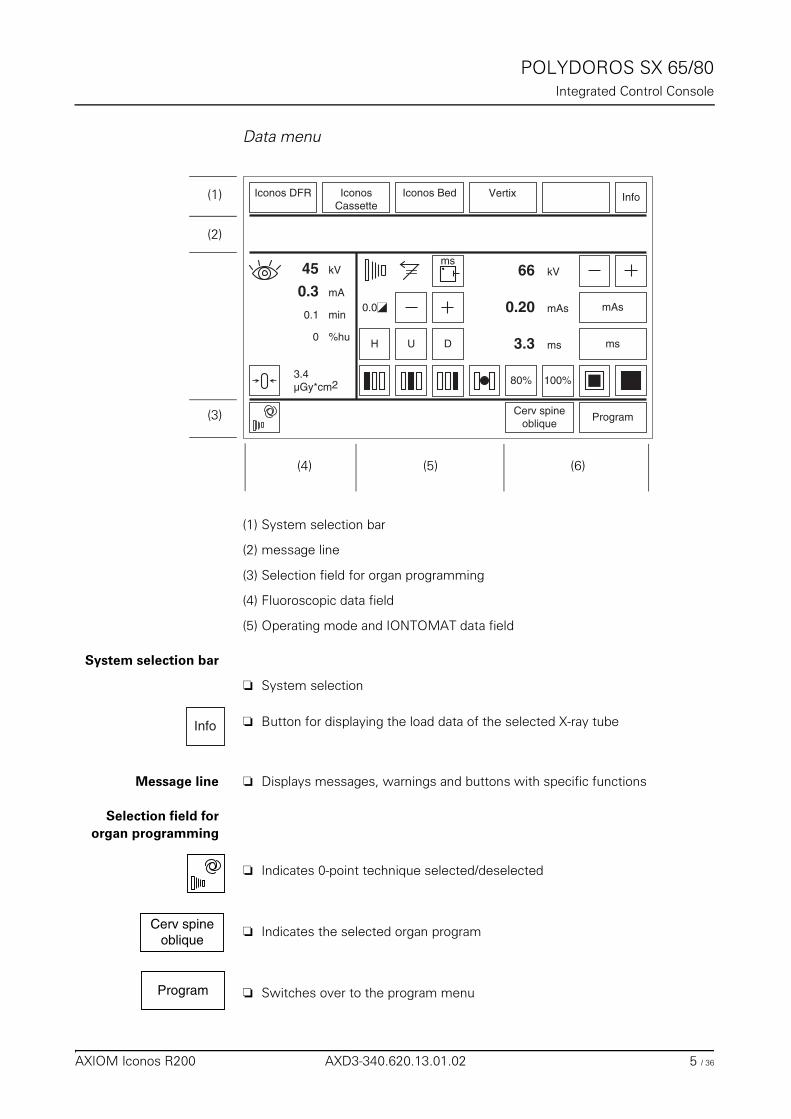
POLYDOROS SX 65/80Integrated Control Console
Data menu
(1) System selection bar
(2) message line
(3) Selection field for organ programming
(4) Fluoroscopic data field
(5) Operating mode and IONTOMAT data field
System selection bar
❏ System selection
❏ Button for displaying the load data of the selected X-ray tube
Message line ❏ Displays messages, warnings and buttons with specific functions
Selection field fororgan programming
❏ Indicates 0-point technique selected/deselected
❏ Indicates the selected organ program
❏ Switches over to the program menu
100%
H U
mAs
ms
kV66
Program
IconosCassette
0.0
Iconos Bed
ms
Iconos DFR
Cerv spineoblique
80%
D
mAs0.20
ms3.3
3.4µGy*cm2
Info
mA
%hu
kV45
0.3
0
min0.1
Vertix(1)
(2)
(3)
(4) (5) (6)
Info
Cerv spineoblique
Program
AXIOM Iconos R200 AXD3-340.620.13.01.02 5 / 36
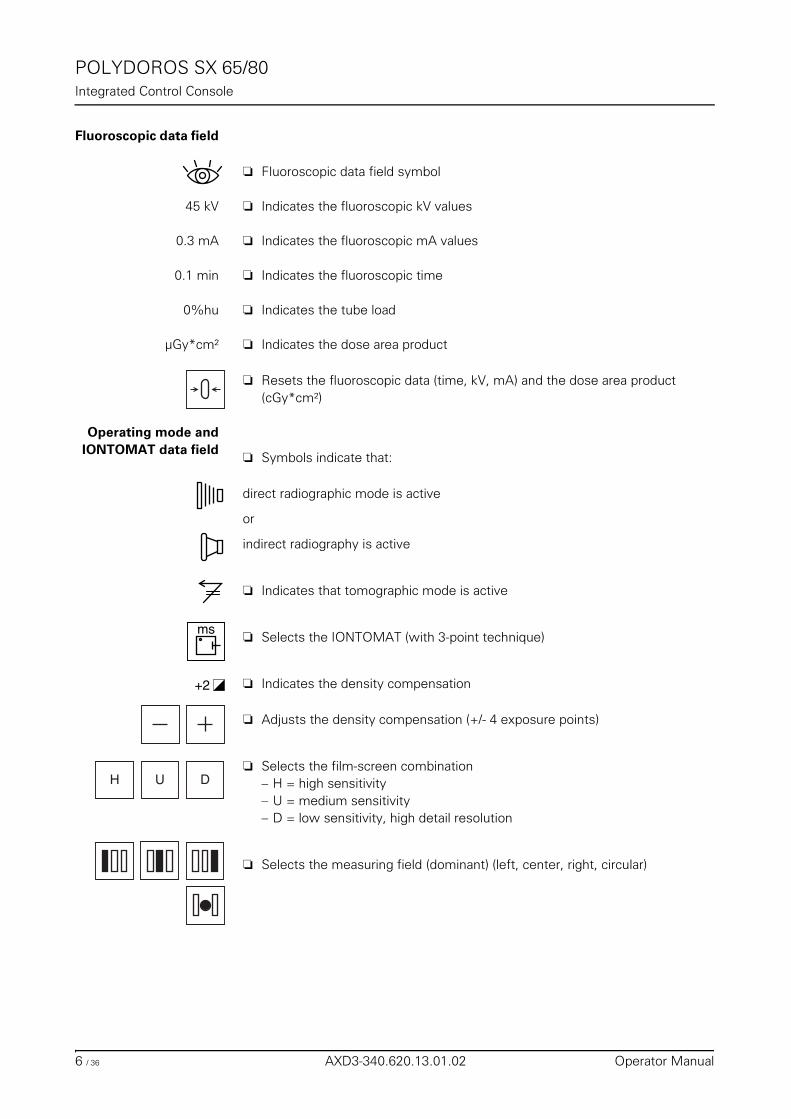
POLYDOROS SX 65/80Integrated Control Console
Fluoroscopic data field
❏ Fluoroscopic data field symbol
45 kV ❏ Indicates the fluoroscopic kV values
0.3 mA ❏ Indicates the fluoroscopic mA values
0.1 min ❏ Indicates the fluoroscopic time
0%hu ❏ Indicates the tube load
µGy*cm² ❏ Indicates the dose area product
❏ Resets the fluoroscopic data (time, kV, mA) and the dose area product (cGy*cm²)
Operating mode andIONTOMAT data field
❏ Symbols indicate that:
direct radiographic mode is active
or
indirect radiography is active
❏ Indicates that tomographic mode is active
❏ Selects the IONTOMAT (with 3-point technique)
❏ Indicates the density compensation
❏ Adjusts the density compensation (+/- 4 exposure points)
❏ Selects the film-screen combination– H = high sensitivity– U = medium sensitivity– D = low sensitivity, high detail resolution
❏ Selects the measuring field (dominant) (left, center, right, circular)
ms
+2
H U D
6 / 36 AXD3-340.620.13.01.02 Operator Manual
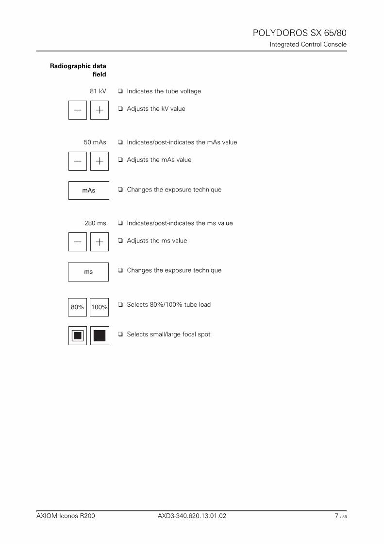
POLYDOROS SX 65/80Integrated Control Console
Radiographic datafield
81 kV ❏ Indicates the tube voltage
❏ Adjusts the kV value
50 mAs ❏ Indicates/post-indicates the mAs value
❏ Adjusts the mAs value
❏ Changes the exposure technique
280 ms ❏ Indicates/post-indicates the ms value
❏ Adjusts the ms value
❏ Changes the exposure technique
❏ Selects 80%/100% tube load
❏ Selects small/large focal spot
mAs
ms
100%80%
AXIOM Iconos R200 AXD3-340.620.13.01.02 7 / 36
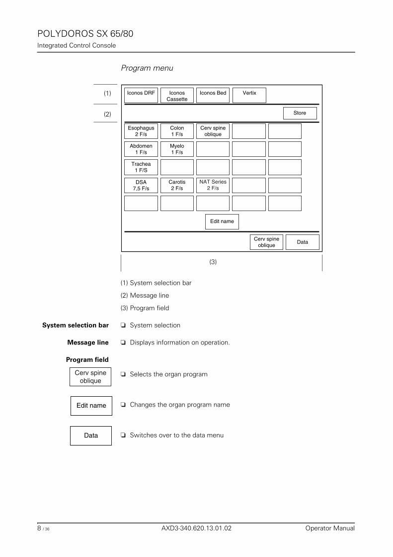
POLYDOROS SX 65/80Integrated Control Console
Program menu
(1) System selection bar
(2) Message line
(3) Program field
System selection bar ❏ System selection
Message line ❏ Displays information on operation.
Program field
❏ Selects the organ program
❏ Changes the organ program name
❏ Switches over to the data menu
Trachea1 F/S
Esophagus2 F/s
DSA7,5 F/s
IconosCassette
Iconos Bed Vertix
Carotis2 F/s
Edit name
Myelo1 F/s
Colon1 F/s
Cerv spineoblique
Abdomen1 F/s
Iconos DRF
DataCerv spine
oblique
NAT Series2 F/s
Store
(1)
(2)
(3)
Cerv spineoblique
Edit name
Data
8 / 36 AXD3-340.620.13.01.02 Operator Manual
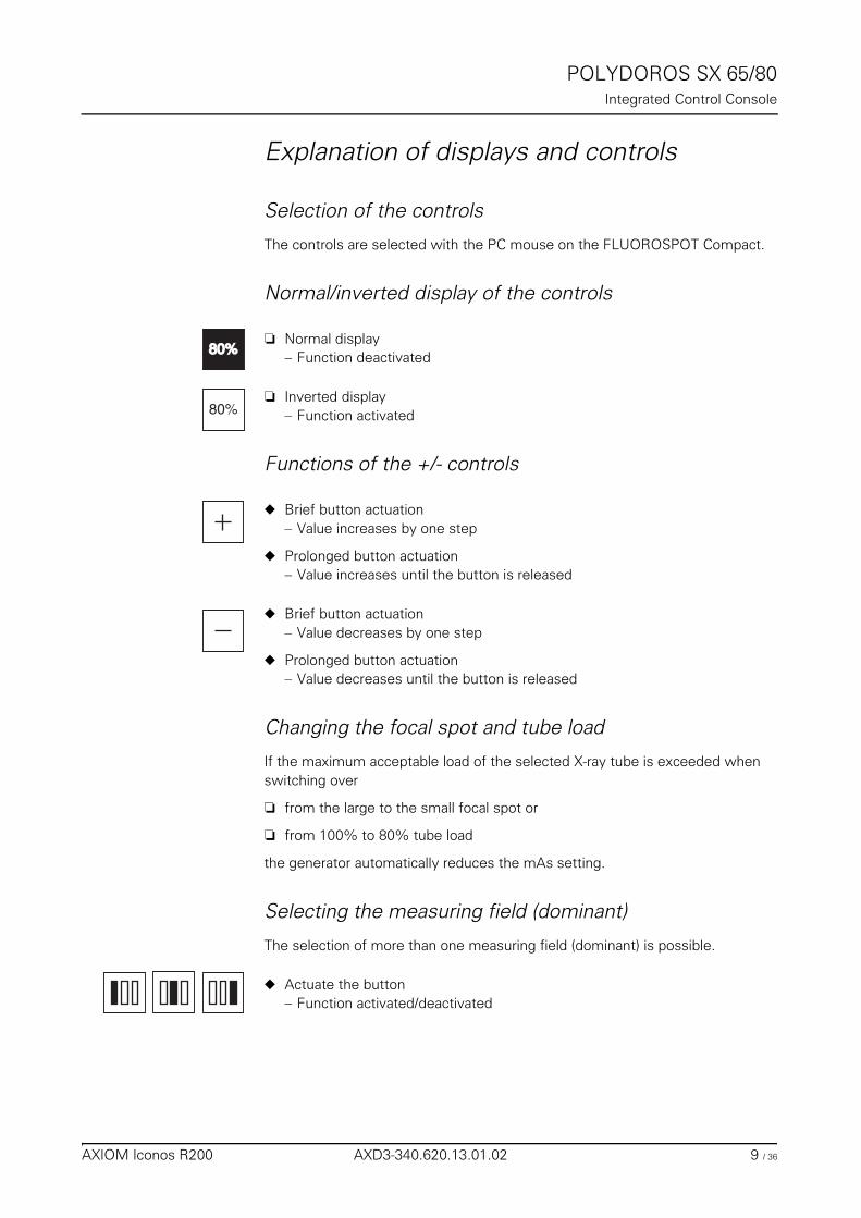
POLYDOROS SX 65/80Integrated Control Console
Explanation of displays and controls
Selection of the controls
The controls are selected with the PC mouse on the FLUOROSPOT Compact.
Normal/inverted display of the controls
❏ Normal display– Function deactivated
❏ Inverted display– Function activated
Functions of the +/- controls
◆ Brief button actuation– Value increases by one step
◆ Prolonged button actuation– Value increases until the button is released
◆ Brief button actuation– Value decreases by one step
◆ Prolonged button actuation– Value decreases until the button is released
Changing the focal spot and tube load
If the maximum acceptable load of the selected X-ray tube is exceeded when switching over
❏ from the large to the small focal spot or
❏ from 100% to 80% tube load
the generator automatically reduces the mAs setting.
Selecting the measuring field (dominant)
The selection of more than one measuring field (dominant) is possible.
◆ Actuate the button– Function activated/deactivated
80%80%
80%
AXIOM Iconos R200 AXD3-340.620.13.01.02 9 / 36
POLYDOROS SX 65/80Integrated Control Console
Measuring field (dominant) display
If either the left or the right dominant selected becomes invalid, e.g. due to colli-mation, the measuring field selected is then shown crossed out.
When the diaphragm is opened again, the previously selected dominants are shown normal again.
Display of the exposure data
After the exposure is completed the actual values of kV, ms and mAs are dis-played.
Messages
General error messages
Each time the system is switched on, an automatic check of all important func-tions is made (test routine).
When a fault is detected the generator is blocked and the fault is displayed as er-ror in the message line and a window with the error message appears on the right side of the monitor screen.
You can cancel the disable status as follows– Acknowledge error message.
If the error message is still displayed, then there is an error in the system. Please call the SIEMENS Uptime Service.
Tube load computer
General
The tube load computer protects the connected X-ray tube assembly from over-loading in radiographic mode.
From the selected exposure factors and from the physical and geometrical prop-erties of the tube assembly it computes the length of the cooldown time that may be necessary.
Furthermore, the tube load computer stores all important operating data of the respective X-ray tube assembly.
The current load (%hu) is constantly displayed.
10 / 36 AXD3-340.620.13.01.02 Operator Manual
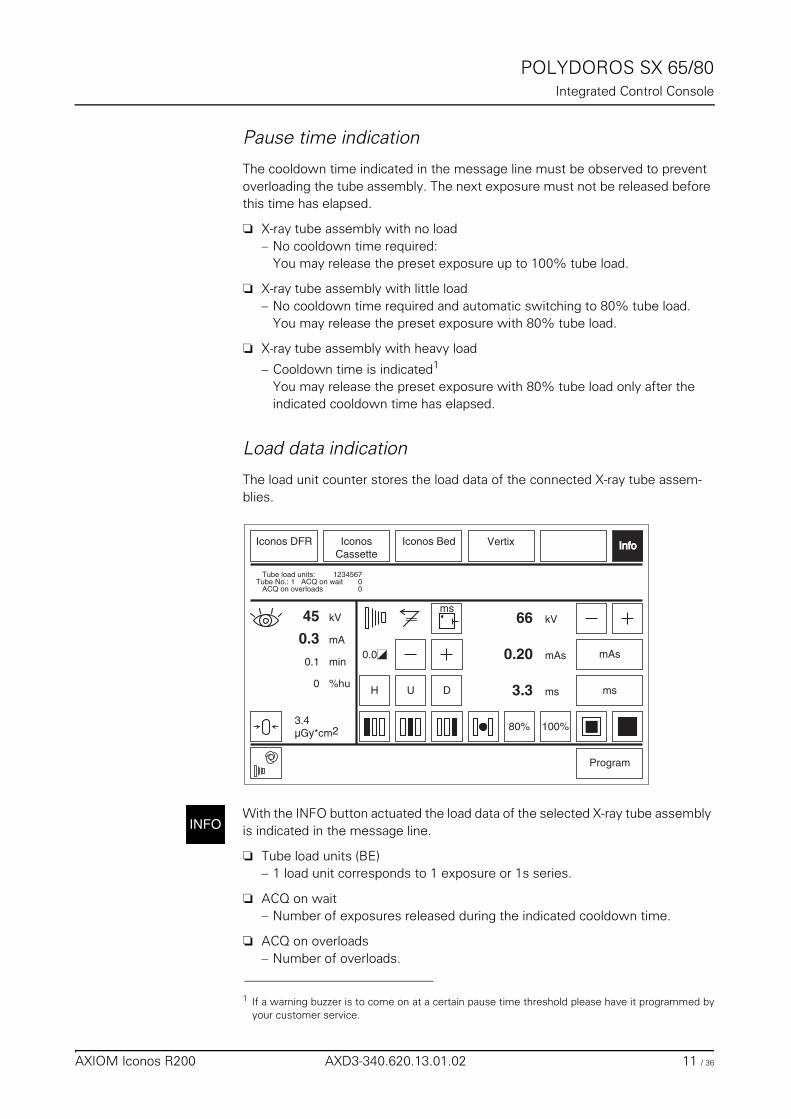
POLYDOROS SX 65/80Integrated Control Console
Pause time indication
The cooldown time indicated in the message line must be observed to prevent overloading the tube assembly. The next exposure must not be released before this time has elapsed.
❏ X-ray tube assembly with no load– No cooldown time required:
You may release the preset exposure up to 100% tube load.
❏ X-ray tube assembly with little load– No cooldown time required and automatic switching to 80% tube load.
You may release the preset exposure with 80% tube load.
❏ X-ray tube assembly with heavy load
– Cooldown time is indicated1
You may release the preset exposure with 80% tube load only after the indicated cooldown time has elapsed.
Load data indication
The load unit counter stores the load data of the connected X-ray tube assem-blies.
With the INFO button actuated the load data of the selected X-ray tube assembly is indicated in the message line.
❏ Tube load units (BE)– 1 load unit corresponds to 1 exposure or 1s series.
❏ ACQ on wait – Number of exposures released during the indicated cooldown time.
❏ ACQ on overloads– Number of overloads.
1 If a warning buzzer is to come on at a certain pause time threshold please have it programmed byyour customer service.
100%
H U
mAs
ms
kV66
Program
IconosCassette
0.0
Iconos Bed
ms
Iconos DFR
80%
D
mAs0.20
ms3.3
3.4µGy*cm2
InfoInfo
mA
%hu
kV45
0.3
0
min0.1
Vertix
123456700
Tube load units:Tube No.: 1 ACQ on wait ACQ on overloads
INFO
AXIOM Iconos R200 AXD3-340.620.13.01.02 11 / 36
POLYDOROS SX 65/80Integrated Control Console
1%hu Indication of the current value of the tube load in relation to the maximum heat storage capacity in per cent.
Functional and safety checks
Daily checks
After switching on
◆ Please make a visual inspection of the displays and signals on the integrated generator control console.
No error message may appear.
The radiation warning lights in the room must not light up.
During the examination
◆ Check the radiation indicator. It may light up only during the duration of the X-ray exposure.
Monthly checks
◆ Perform a functional check of the automatic exposure control, as described in Register “Safety”.
Legally required checks
Obtain information in Register “Safety”.
Maintenance intervals
Maintenance must be performed annually to maintain the safety and functioning of the generator.If you have not concluded a maintenance contract, please notify the SIEMENS Uptime Service in good time.
INFO button is not active if an information is already present on the message line.
If a radiation warning light lights up without actuating a switch
◆ immediately switch off the X-ray system through emergency off and
◆ notify the SIEMENS Uptime Service.
12 / 36 AXD3-340.620.13.01.02 Operator Manual
POLYDOROS SX 65/80Integrated Control Console
Fluoroscopy➩ For further information refer the FLUOROSOT Compact Operator Manual
Releasing fluoroscopy
Fluoroscopy is released via the fluoroscopy foot switch.
Selecting the fluoroscopic mode1
Fluoroscopy with automatic control
With the automatic stage buttons on the unit, select the required characteristic curve for the automatic dose rate control.
High-contrast fluoroscopy1
Is a special case of fluoroscopy with automatic control. It is selected with the 2nd pressure point of a two-stage foot switch. The mode is indicated acoustically.
Fluoroscopic data
The fluoroscopic data of kV, mA, time and dose area product are displayed on the integrated generator control console.
Display of the kV and mA values
❏ During fluoroscopy:– the current kV and mA values are indicated continuously
❏ After the end of fluoroscopy:– the mean value of kV and mA for the examination
Display of the fluoroscopic time
Continuous display of cumulative time in minutes during the examination
Display of the dose area product
Continuous display of the dose area product accumulated in the examination.
Resetting the fluoroscopic data1
When the examination is finished, record the fluoroscopic data displayed and
◆ actuate the Reset button.– The displays for the fluoroscopic data and for the dose area product are
reset to zero.
1 depending on the system configuration
AXIOM Iconos R200 AXD3-340.620.13.01.02 13 / 36
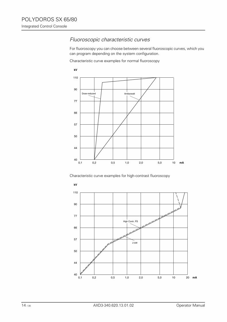
POLYDOROS SX 65/80Integrated Control Console
Fluoroscopic characteristic curves
For fluoroscopy you can choose between several fluoroscopic curves, which you can program depending on the system configuration.
Characteristic curve examples for normal fluoroscopy
Characteristic curve examples for high-contrast fluoroscopy
kV
40
44
50
57
66
77
90
110
mA0,1 0,2 0,5 1,0 2,0 5,0 10
Dose-reduced Antiisowatt
kV
40
44
50
57
66
77
90
110
mA0,1 0,2 0,5 1,0 2,0 5,0 10 20
High Contr. PS
2 kW
14 / 36 AXD3-340.620.13.01.02 Operator Manual

POLYDOROS SX 65/80Integrated Control Console
Fluoroscopic time limit
After a fluoroscopic time of 10 minutes1, fluoroscopy switches off automatically and cannot be switched on again.
To continue working,
◆ let go of the fluoroscopy switch and actuate it again.
Exposure
Exposure release
You can release an exposure either with the release button on the generator ON/OFF console2, on the system control console3 or with the exposure release foot switch in controlroom.
You can release an exposure if
❏ no error message appears, and
❏ none of the displays (kV, mAs, ms) flashes
The radiation indicator lights up and a signal sounds during the exposure release.
❏ Observe the following to increase the life of the tube assembly:– If possible always select 80% tube load at the generator.– It is essential that you program 80% tube load in the programs with small
focal spot and a tube voltage less than 70 kV.– Work with the large focal spot below 70 kV tube voltage, if possible.– Keep the prep time short and possibly “push through” to keep this time
short.– Let go of the exposure release button immediately after the exposure.
1 At the wish of the customer, this parameter can be changed by SIEMENS Uptime Service, in accor-dance with country-specific regulations.
2 Not possible in DFR and Cassette mode;in Vertix mode with ACSS only when tube unit is rotated 180°
3 Not possible in Bed mode and Vertix mode
Check the selected exposure data on the integrated generator control console before every radiation release.
The above instructions should be observed especially at workstations with high patient throughput (accident stations) to counteract premature wear of the X-ray tube assembly.
AXIOM Iconos R200 AXD3-340.620.13.01.02 15 / 36
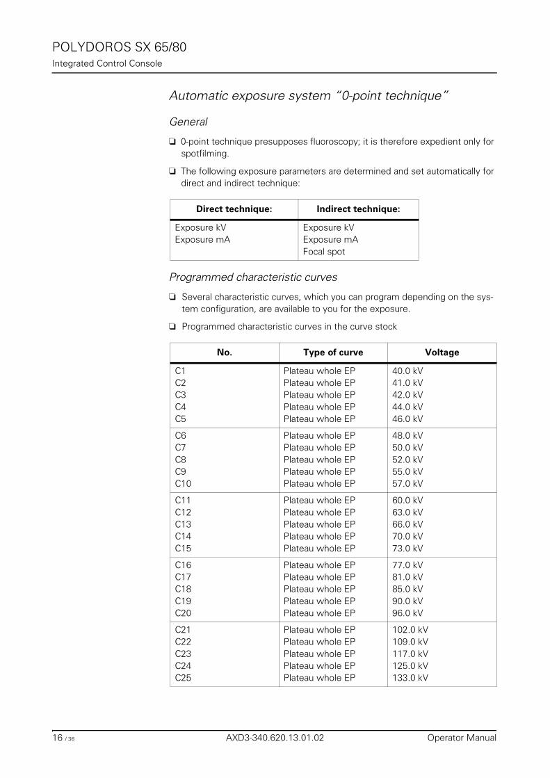
POLYDOROS SX 65/80Integrated Control Console
Automatic exposure system “0-point technique”
General 0
❏ 0-point technique presupposes fluoroscopy; it is therefore expedient only for spotfilming.
❏ The following exposure parameters are determined and set automatically for direct and indirect technique:
Programmed characteristic curves
❏ Several characteristic curves, which you can program depending on the sys-tem configuration, are available to you for the exposure.
❏ Programmed characteristic curves in the curve stock
Direct technique: Indirect technique:
Exposure kVExposure mA
Exposure kVExposure mAFocal spot
No. Type of curve Voltage
C1C2C3C4C5
Plateau whole EPPlateau whole EPPlateau whole EPPlateau whole EPPlateau whole EP
40.0 kV41.0 kV42.0 kV44.0 kV46.0 kV
C6C7C8C9C10
Plateau whole EPPlateau whole EPPlateau whole EPPlateau whole EPPlateau whole EP
48.0 kV50.0 kV52.0 kV55.0 kV57.0 kV
C11C12C13C14C15
Plateau whole EPPlateau whole EPPlateau whole EPPlateau whole EPPlateau whole EP
60.0 kV63.0 kV66.0 kV70.0 kV73.0 kV
C16C17C18C19C20
Plateau whole EPPlateau whole EPPlateau whole EPPlateau whole EPPlateau whole EP
77.0 kV81.0 kV85.0 kV90.0 kV96.0 kV
C21C22C23C24C25
Plateau whole EPPlateau whole EPPlateau whole EPPlateau whole EPPlateau whole EP
102.0 kV109.0 kV117.0 kV125.0 kV133.0 kV
16 / 36 AXD3-340.620.13.01.02 Operator Manual
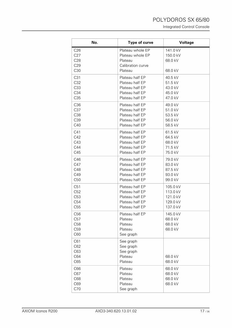
POLYDOROS SX 65/80Integrated Control Console
C26C27C28C29C30
Plateau whole EPPlateau whole EPPlateauCalibration curvePlateau
141.0 kV150.0 kV68.0 kV
68.0 kV
C31C32C33C34C35
Plateau half EPPlateau half EPPlateau half EPPlateau half EPPlateau half EP
40.5 kV51.5 kV43.0 kV45.0 kV47.0 kV
C36C37C38C39C40
Plateau half EPPlateau half EPPlateau half EPPlateau half EPPlateau half EP
49.0 kV51.0 kV53.5 kV56.0 kV58.5 kV
C41C42C43C44C45
Plateau half EPPlateau half EPPlateau half EPPlateau half EPPlateau half EP
61.5 kV64.5 kV68.0 kV71.5 kV75.0 kV
C46C47C48C49C50
Plateau half EPPlateau half EPPlateau half EPPlateau half EPPlateau half EP
79.0 kV83.0 kV87.5 kV93.0 kV99.0 kV
C51C52C53C54C55
Plateau half EPPlateau half EPPlateau half EPPlateau half EPPlateau half EP
105.0 kV113.0 kV121.0 kV129.0 kV137.0 kV
C56C57C58C59C60
Plateau half EPPlateauPlateauPlateauSee graph
145.0 kV68.0 kV68.0 kV68.0 kV
C61C62C63C64C65
See graphSee graphSee graphPlateauPlateau
68.0 kV68.0 kV
C66C67C68C69C70
PlateauPlateauPlateauPlateauSee graph
68.0 kV68.0 kV68.0 kV68.0 kV
No. Type of curve Voltage
AXIOM Iconos R200 AXD3-340.620.13.01.02 17 / 36
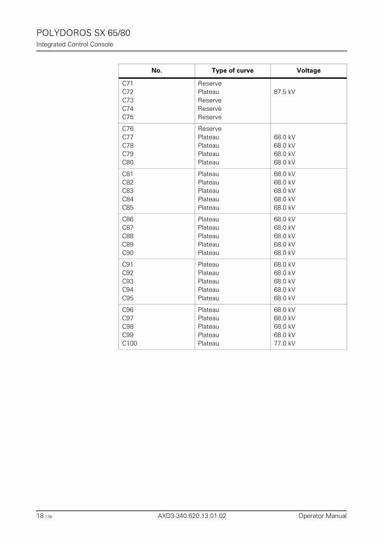
POLYDOROS SX 65/80Integrated Control Console
C71C72C73C74C75
ReservePlateauReserveReserveReserve
87.5 kV
C76C77C78C79C80
ReservePlateauPlateauPlateauPlateau
68.0 kV68.0 kV68.0 kV68.0 kV
C81C82C83C84C85
PlateauPlateauPlateauPlateauPlateau
68.0 kV68.0 kV68.0 kV68.0 kV68.0 kV
C86C87C88C89C90
PlateauPlateauPlateauPlateauPlateau
68.0 kV68.0 kV68.0 kV68.0 kV68.0 kV
C91C92C93C94C95
PlateauPlateauPlateauPlateauPlateau
68.0 kV68.0 kV68.0 kV68.0 kV68.0 kV
C96C97C98C99C100
PlateauPlateauPlateauPlateauPlateau
68.0 kV68.0 kV68.0 kV68.0 kV77.0 kV
No. Type of curve Voltage
18 / 36 AXD3-340.620.13.01.02 Operator Manual
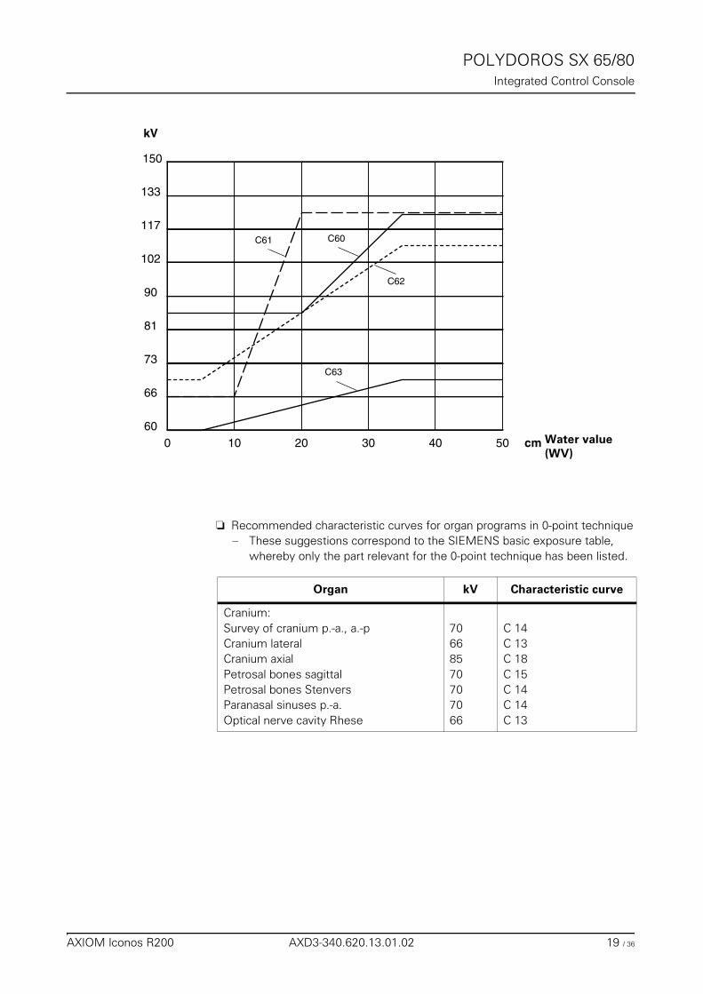
POLYDOROS SX 65/80Integrated Control Console
❏ Recommended characteristic curves for organ programs in 0-point technique– These suggestions correspond to the SIEMENS basic exposure table,
whereby only the part relevant for the 0-point technique has been listed.
kV
60
66
73
81
90
102
0 10 20 30 40
117
133
cm Wasserwert (WW)
50
C60C61
C62
C63
150
Water value(WV)
Organ kV Characteristic curve
Cranium:Survey of cranium p.-a., a.-pCranium lateralCranium axialPetrosal bones sagittalPetrosal bones StenversParanasal sinuses p.-a.Optical nerve cavity Rhese
70668570707066
C 14C 13C 18C 15C 14C 14C 13
AXIOM Iconos R200 AXD3-340.620.13.01.02 19 / 36
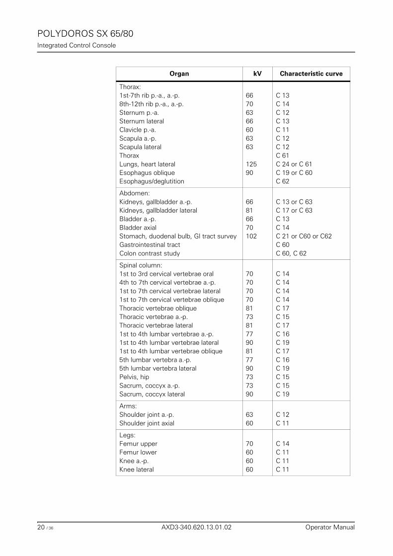
POLYDOROS SX 65/80Integrated Control Console
Thorax:1st-7th rib p.-a., a.-p.8th-12th rib p.-a., a.-p.Sternum p.-a.Sternum lateralClavicle p.-a.Scapula a.-p.Scapula lateralThoraxLungs, heart lateralEsophagus obliqueEsophagus/deglutition
66706366606363
12590
C 13C 14C 12C 13C 11C 12C 12C 61C 24 or C 61C 19 or C 60C 62
Abdomen:Kidneys, gallbladder a.-p.Kidneys, gallbladder lateralBladder a.-p.Bladder axialStomach, duodenal bulb, GI tract surveyGastrointestinal tractColon contrast study
66816670102
C 13 or C 63C 17 or C 63C 13C 14C 21 or C60 or C62C 60C 60, C 62
Spinal column:1st to 3rd cervical vertebrae oral4th to 7th cervical vertebrae a.-p.1st to 7th cervical vertebrae lateral1st to 7th cervical vertebrae obliqueThoracic vertebrae obliqueThoracic vertebrae a.-p.Thoracic vertebrae lateral1st to 4th lumbar vertebrae a.-p.1st to 4th lumbar vertebrae lateral1st to 4th lumbar vertebrae oblique5th lumbar vertebra a.-p.5th lumbar vertebra lateralPelvis, hipSacrum, coccyx a.-p.Sacrum, coccyx lateral
707070708173817790817790737390
C 14C 14C 14C 14C 17C 15C 17C 16C 19C 17C 16C 19C 15C 15C 19
Arms:Shoulder joint a.-p.Shoulder joint axial
6360
C 12C 11
Legs:Femur upperFemur lowerKnee a.-p.Knee lateral
70606060
C 14C 11C 11C 11
Organ kV Characteristic curve
20 / 36 AXD3-340.620.13.01.02 Operator Manual
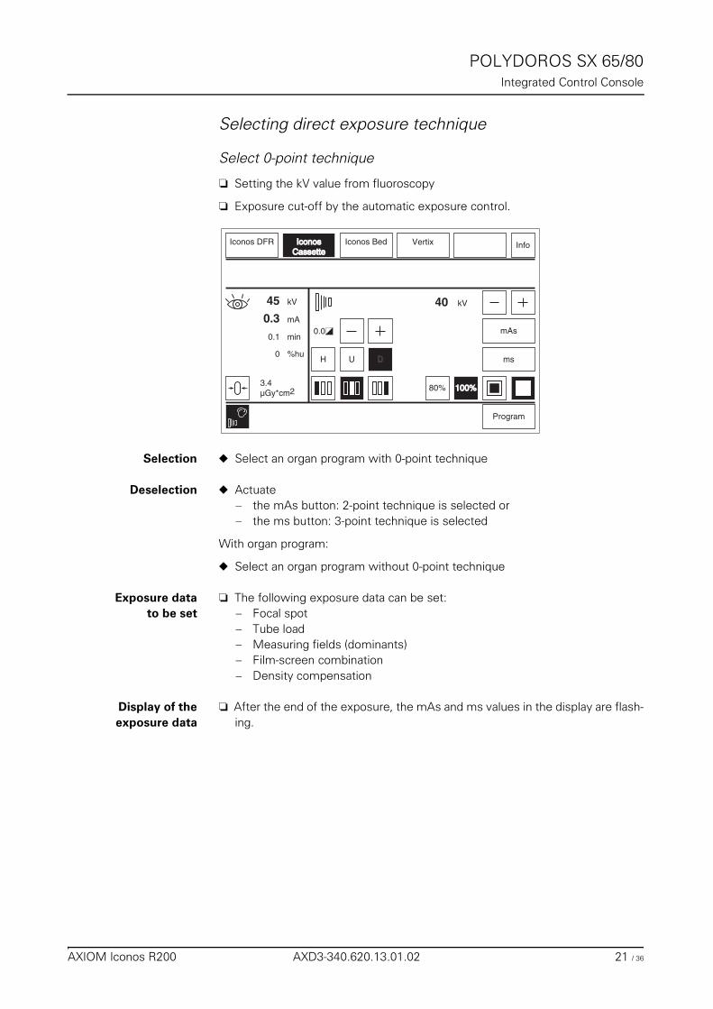
POLYDOROS SX 65/80Integrated Control Console
Selecting direct exposure technique 0
Select 0-point technique 0
❏ Setting the kV value from fluoroscopy
❏ Exposure cut-off by the automatic exposure control.
Selection ◆ Select an organ program with 0-point technique
Deselection ◆ Actuate – the mAs button: 2-point technique is selected or– the ms button: 3-point technique is selected
With organ program:
◆ Select an organ program without 0-point technique
Exposure datato be set
❏ The following exposure data can be set:– Focal spot– Tube load– Measuring fields (dominants)– Film-screen combination– Density compensation
Display of theexposure data
❏ After the end of the exposure, the mAs and ms values in the display are flash-ing.
100%100%
H U
mAs
ms
kV40
Program
IconosIconosCassetteCassette
0.0
Iconos BedIconos DFR
80%
D
3.4µGy*cm2
Info
mA
%hu
kV45
0.3
0
min0.1
Vertix
AXIOM Iconos R200 AXD3-340.620.13.01.02 21 / 36
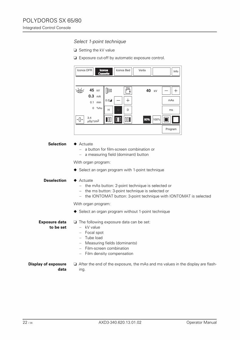
POLYDOROS SX 65/80Integrated Control Console
Select 1-point technique 0
❏ Setting the kV value
❏ Exposure cut-off by automatic exposure control.
Selection ◆ Actuate – a button for film-screen combination or– a measuring field (dominant) button
With organ program:
◆ Select an organ program with 1-point technique
Deselection ◆ Actuate– the mAs button: 2-point technique is selected or– the ms button: 3-point technique is selected or– the IONTOMAT button: 3-point technique with IONTOMAT is selected
With organ program:
◆ Select an organ program without 1-point technique
Exposure datato be set
❏ The following exposure data can be set:– kV value– Focal spot– Tube load– Measuring fields (dominants)– Film-screen combination– Film density compensation
Display of exposuredata
❏ After the end of the exposure, the mAs and ms values in the display are flash-ing.
100%
H U
mAs
ms
kV40
Program
IconosIconosCassetteCassette
0.0
Iconos Bed
ms
Iconos DFR
80%80%
D
3.4µGy*cm2
Info
mA
%hu
kV45
0.3
0
min0.1
Vertix
22 / 36 AXD3-340.620.13.01.02 Operator Manual
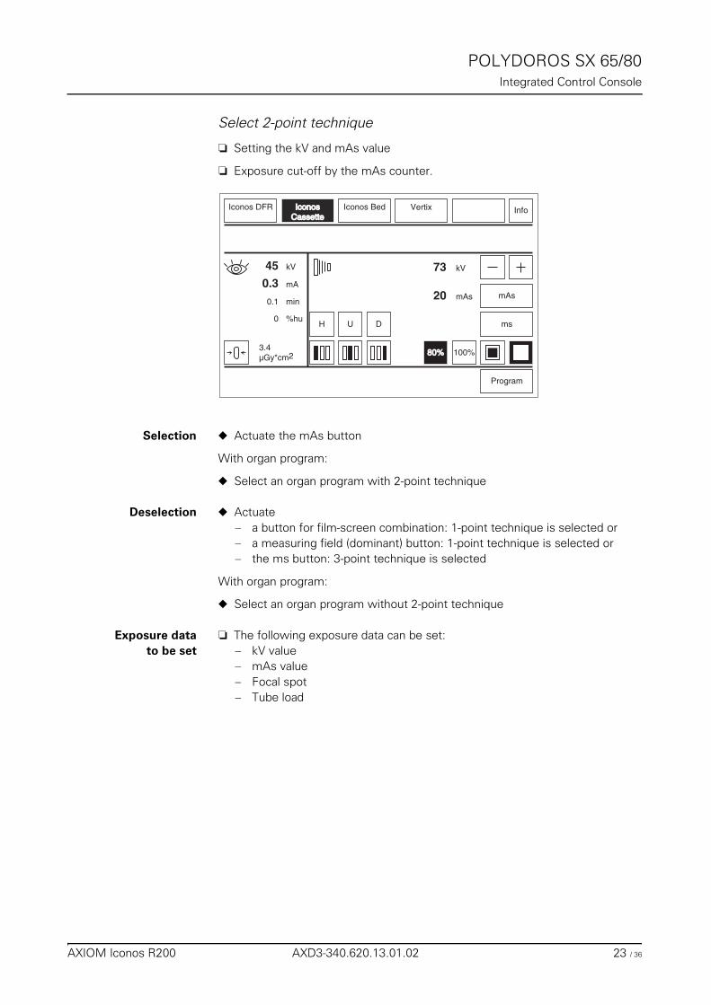
POLYDOROS SX 65/80Integrated Control Console
Select 2-point technique 0
❏ Setting the kV and mAs value
❏ Exposure cut-off by the mAs counter.
Selection ◆ Actuate the mAs button
With organ program:
◆ Select an organ program with 2-point technique
Deselection ◆ Actuate– a button for film-screen combination: 1-point technique is selected or– a measuring field (dominant) button: 1-point technique is selected or– the ms button: 3-point technique is selected
With organ program:
◆ Select an organ program without 2-point technique
Exposure datato be set
❏ The following exposure data can be set:– kV value– mAs value– Focal spot– Tube load
100%
H U
mAs
ms
kV73
Program
IconosIconosCassetteCassette
Iconos BedIconos DFR
80%80%
D
mAs20
3.4µGy*cm2
Info
mA
%hu
kV45
0.3
0
min0.1
Vertix
AXIOM Iconos R200 AXD3-340.620.13.01.02 23 / 36
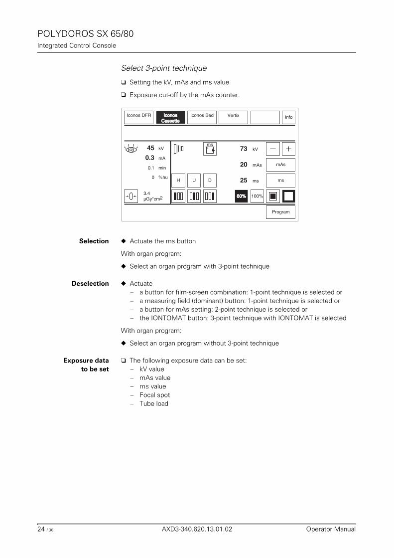
POLYDOROS SX 65/80Integrated Control Console
Select 3-point technique 0
❏ Setting the kV, mAs and ms value
❏ Exposure cut-off by the mAs counter.
Selection ◆ Actuate the ms button
With organ program:
◆ Select an organ program with 3-point technique
Deselection ◆ Actuate– a button for film-screen combination: 1-point technique is selected or– a measuring field (dominant) button: 1-point technique is selected or– a button for mAs setting: 2-point technique is selected or– the IONTOMAT button: 3-point technique with IONTOMAT is selected
With organ program:
◆ Select an organ program without 3-point technique
Exposure datato be set
❏ The following exposure data can be set:– kV value– mAs value– ms value– Focal spot– Tube load
100%
H U
mAs
ms
kV73
Program
IconosIconosCassetteCassette
Iconos Bed
ms
Iconos DFR
80%80%
D
mAs20
ms25
3.4µGy*cm2
Info
mA
%hu
kV45
0.3
0
min0.1
Vertix
24 / 36 AXD3-340.620.13.01.02 Operator Manual
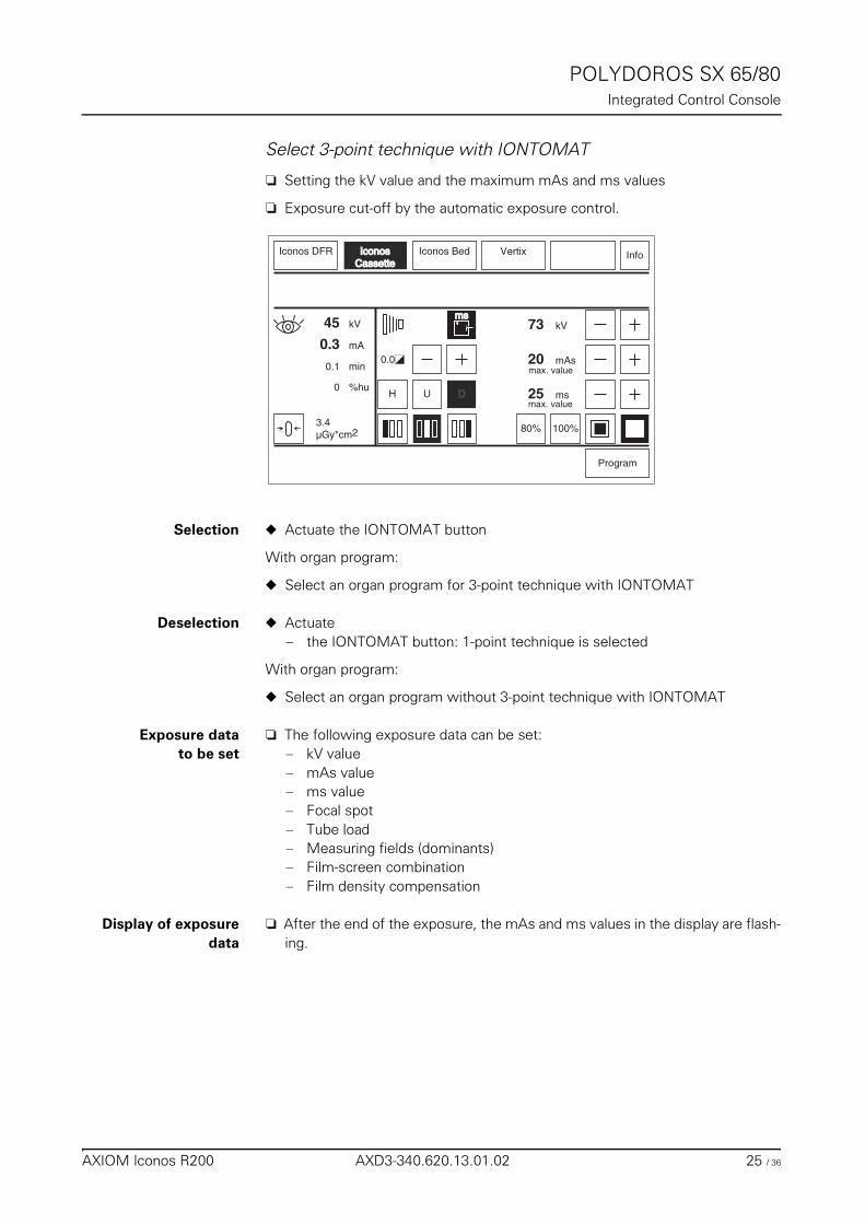
POLYDOROS SX 65/80Integrated Control Console
Select 3-point technique with IONTOMAT 0
❏ Setting the kV value and the maximum mAs and ms values
❏ Exposure cut-off by the automatic exposure control.
Selection ◆ Actuate the IONTOMAT button
With organ program:
◆ Select an organ program for 3-point technique with IONTOMAT
Deselection ◆ Actuate– the IONTOMAT button: 1-point technique is selected
With organ program:
◆ Select an organ program without 3-point technique with IONTOMAT
Exposure datato be set
❏ The following exposure data can be set:– kV value– mAs value– ms value– Focal spot– Tube load– Measuring fields (dominants)– Film-screen combination– Film density compensation
Display of exposuredata
❏ After the end of the exposure, the mAs and ms values in the display are flash-ing.
100%
H U
kV73
Program
IconosIconosCassetteCassette
0.0
Iconos Bed
msms
Iconos DFR
80%
D
mAs20
ms25
3.4µGy*cm2
Info
mA
%hu
kV45
0.3
0
min0.1
Vertix
max. value
max. value
AXIOM Iconos R200 AXD3-340.620.13.01.02 25 / 36
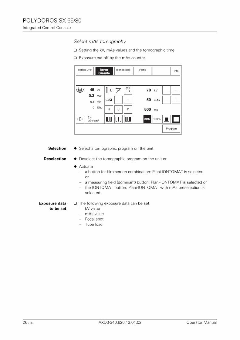
POLYDOROS SX 65/80Integrated Control Console
Select mAs tomography 0
❏ Setting the kV, mAs values and the tomographic time
❏ Exposure cut-off by the mAs counter.
Selection ◆ Select a tomographic program on the unit
Deselection ◆ Deselect the tomographic program on the unit or
◆ Actuate– a button for film-screen combination: Plani-IONTOMAT is selected
or– a measuring field (dominant) button: Plani-IONTOMAT is selected or– the IONTOMAT button: Plani-IONTOMAT with mAs preselection is
selected
Exposure datato be set
❏ The following exposure data can be set:– kV value– mAs value– Focal spot– Tube load
100%
H U
kV70
Program
IconosIconosCassetteCassette
0.0
Iconos Bed
ms
Iconos DFR
80%80%
D
mAs50
ms800
3.4µGy*cm2
Info
mA
%hu
kV45
0.3
0
min0.1
Vertix
26 / 36 AXD3-340.620.13.01.02 Operator Manual
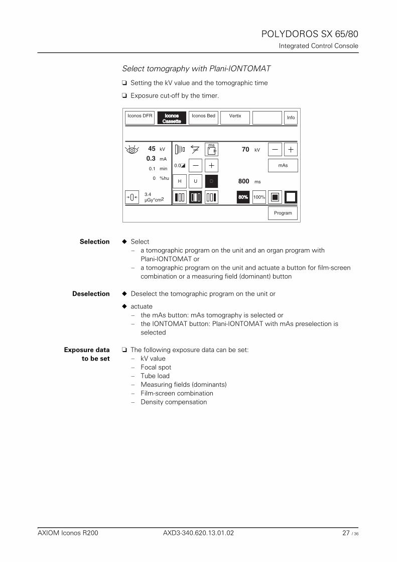
POLYDOROS SX 65/80Integrated Control Console
Select tomography with Plani-IONTOMAT 0
❏ Setting the kV value and the tomographic time
❏ Exposure cut-off by the timer.
Selection ◆ Select– a tomographic program on the unit and an organ program with
Plani-IONTOMAT or– a tomographic program on the unit and actuate a button for film-screen
combination or a measuring field (dominant) button
Deselection ◆ Deselect the tomographic program on the unit or
◆ actuate– the mAs button: mAs tomography is selected or– the IONTOMAT button: Plani-IONTOMAT with mAs preselection is
selected
Exposure datato be set
❏ The following exposure data can be set:– kV value– Focal spot– Tube load– Measuring fields (dominants)– Film-screen combination– Density compensation
100%
H U
kV70
Program
IconosIconosCassetteCassette
0.0
Iconos Bed
ms
Iconos DFR
80%80%
D ms800
3.4µGy*cm2
Info
mA
%hu
kV45
0.3
0
min0.1
Vertix
mAs
AXIOM Iconos R200 AXD3-340.620.13.01.02 27 / 36
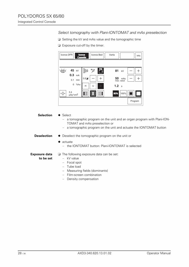
POLYDOROS SX 65/80Integrated Control Console
Select tomography with Plani-IONTOMAT and mAs preselection 0
❏ Setting the kV and mAs value and the tomographic time
❏ Exposure cut-off by the timer.
Selection ◆ Select– a tomographic program on the unit and an organ program with Plani-ION-
TOMAT and mAs preselection or– a tomographic program on the unit and actuate the IONTOMAT button
Deselection ◆ Deselect the tomographic program on the unit or
◆ actuate– the IONTOMAT button: Plani-IONTOMAT is selected
Exposure datato be set
❏ The following exposure data can be set:– kV value– Focal spot– Tube load– Measuring fields (dominants)– Film-screen combination– Density compensation
100%
H U
kV81
Program
IconosIconosCassetteCassette
0.0
Iconos Bed
msms
Iconos DFR
80%80%
D s1.2
3.4µGy*cm2
Info
mA
%hu
kV45
0.3
0
min0.1
Vertix
mAs50max. value
28 / 36 AXD3-340.620.13.01.02 Operator Manual
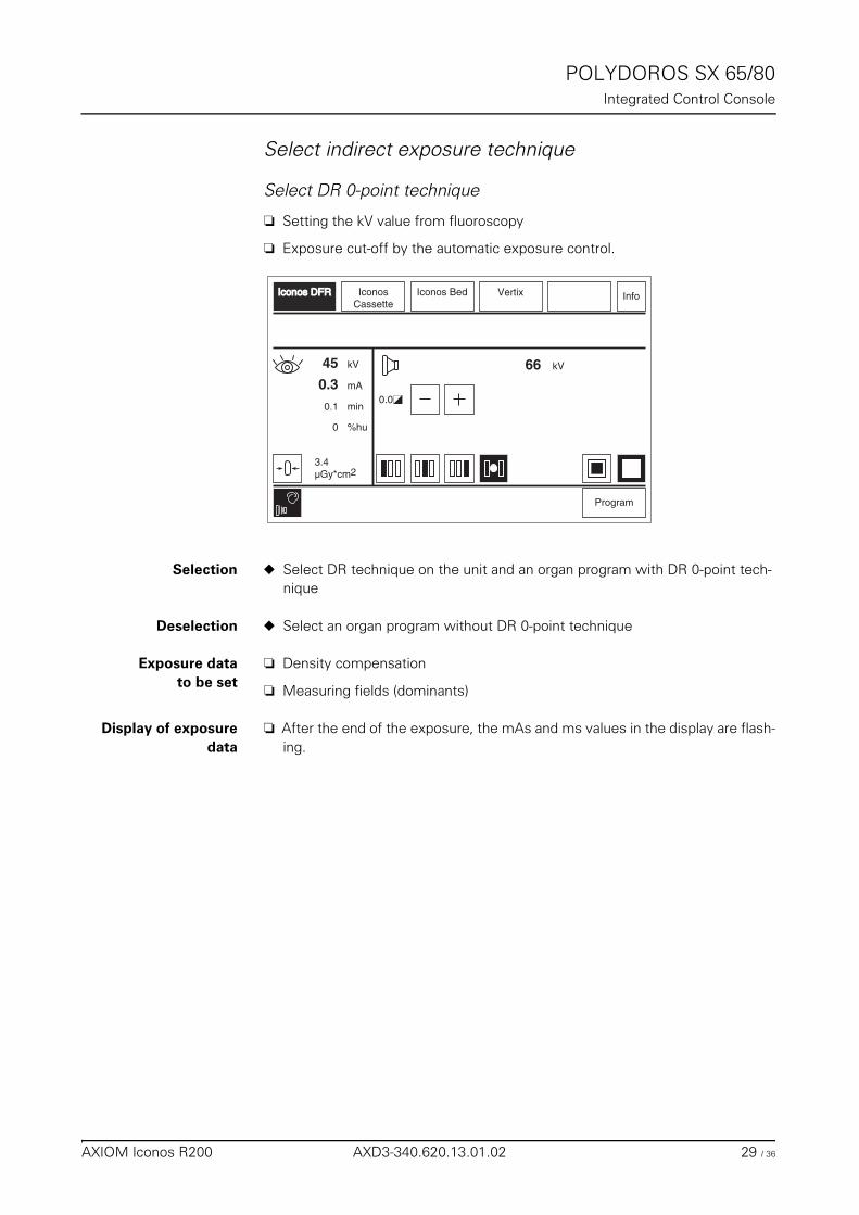
POLYDOROS SX 65/80Integrated Control Console
Select indirect exposure technique
Select DR 0-point technique 0
❏ Setting the kV value from fluoroscopy
❏ Exposure cut-off by the automatic exposure control.
Selection ◆ Select DR technique on the unit and an organ program with DR 0-point tech-nique
Deselection ◆ Select an organ program without DR 0-point technique
Exposure datato be set
❏ Density compensation
❏ Measuring fields (dominants)
Display of exposuredata
❏ After the end of the exposure, the mAs and ms values in the display are flash-ing.
kV66
Program
IconosCassette
0.0
Iconos BedIconos DFRIconos DFR
3.4µGy*cm2
Info
mA
%hu
kV45
0.3
0
min0.1
Vertix
AXIOM Iconos R200 AXD3-340.620.13.01.02 29 / 36
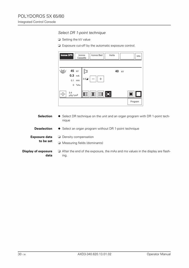
POLYDOROS SX 65/80Integrated Control Console
Select DR 1-point technique 0
❏ Setting the kV value
❏ Exposure cut-off by the automatic exposure control.
Selection ◆ Select DR technique on the unit and an organ program with DR 1-point tech-nique
Deselection ◆ Select an organ program without DR 1-point technique
Exposure datato be set
❏ Density compensation
❏ Measuring fields (dominants)
Display of exposuredata
❏ After the end of the exposure, the mAs and ms values in the display are flash-ing.
kV40
Program
IconosCassette
0.0
Iconos BedIconos DFRIconos DFR
3.4µGy*cm2
Info
mA
%hu
kV45
0.3
0
min0.1
Vertix
30 / 36 AXD3-340.620.13.01.02 Operator Manual
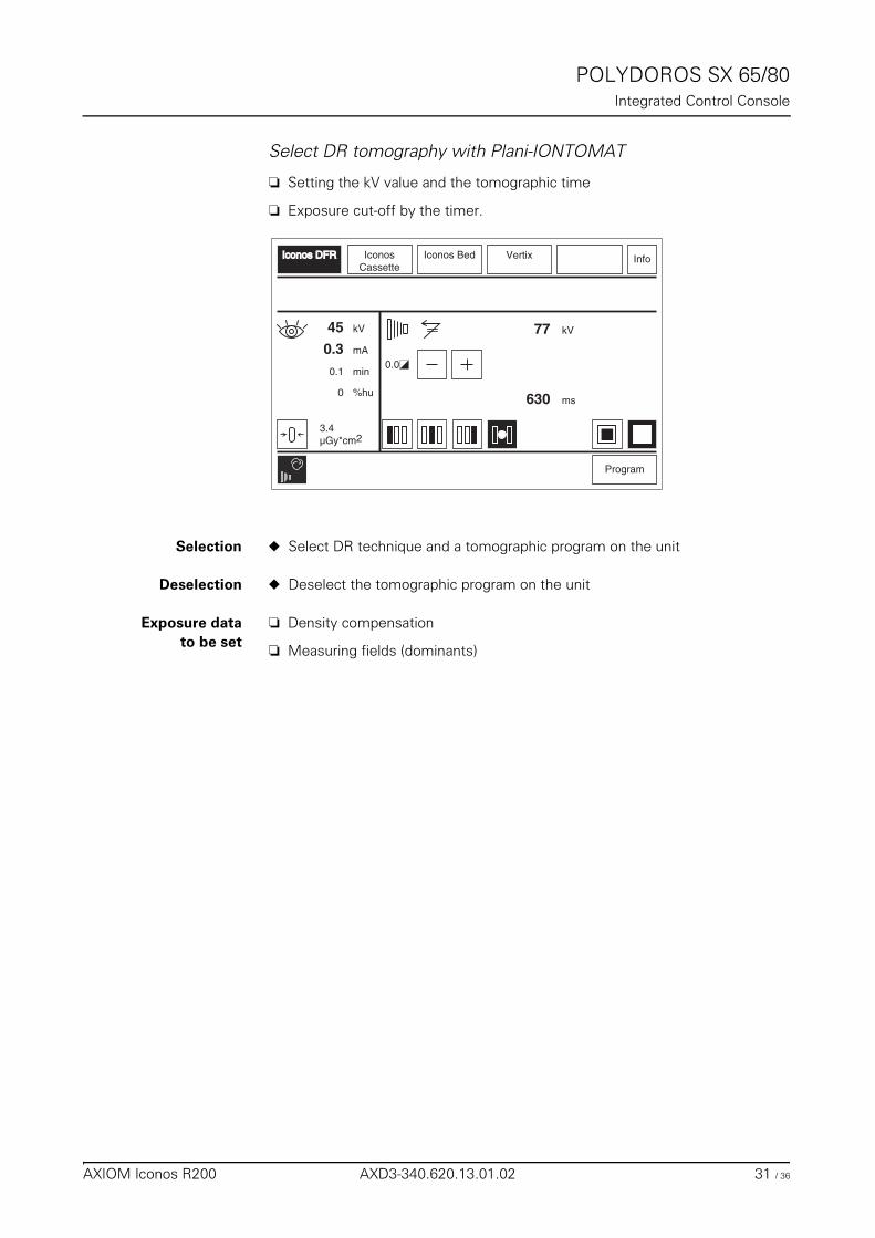
POLYDOROS SX 65/80Integrated Control Console
Select DR tomography with Plani-IONTOMAT 0
❏ Setting the kV value and the tomographic time
❏ Exposure cut-off by the timer.
Selection ◆ Select DR technique and a tomographic program on the unit
Deselection ◆ Deselect the tomographic program on the unit
Exposure datato be set
❏ Density compensation
❏ Measuring fields (dominants)
kV77
Program
IconosCassette
0.0
Iconos BedIconos DFRIconos DFR
ms630
3.4µGy*cm2
Info
mA
%hu
kV45
0.3
0
min0.1
Vertix
AXIOM Iconos R200 AXD3-340.620.13.01.02 31 / 36
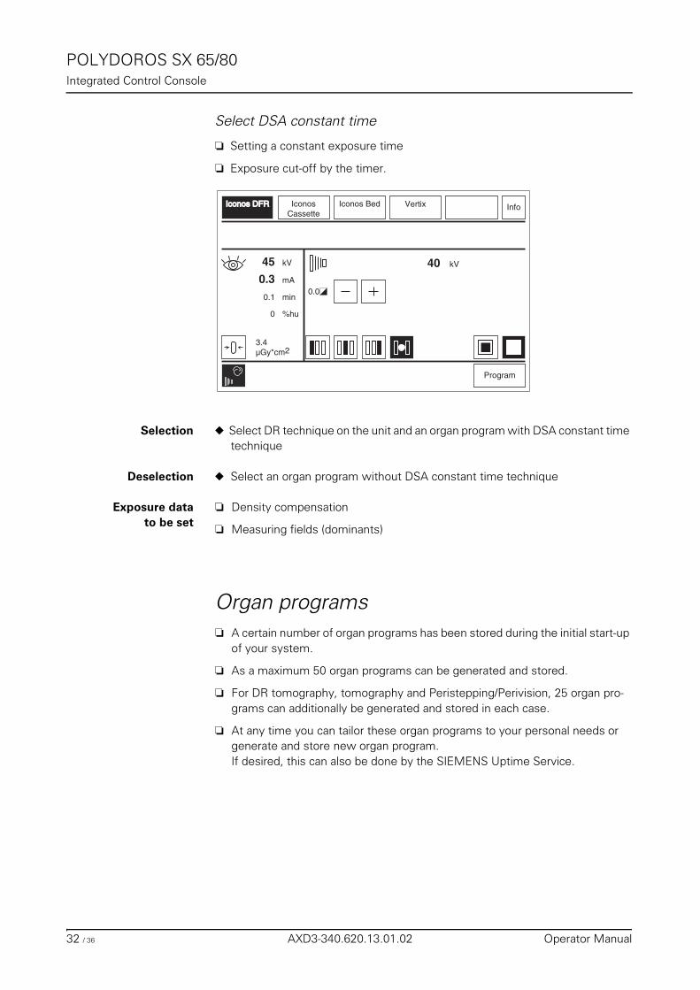
POLYDOROS SX 65/80Integrated Control Console
Select DSA constant time 0
❏ Setting a constant exposure time
❏ Exposure cut-off by the timer.
Selection ◆ Select DR technique on the unit and an organ program with DSA constant time technique
Deselection ◆ Select an organ program without DSA constant time technique
Exposure datato be set
❏ Density compensation
❏ Measuring fields (dominants)
Organ programs ❏ A certain number of organ programs has been stored during the initial start-up
of your system.
❏ As a maximum 50 organ programs can be generated and stored.
❏ For DR tomography, tomography and Peristepping/Perivision, 25 organ pro-grams can additionally be generated and stored in each case.
❏ At any time you can tailor these organ programs to your personal needs or generate and store new organ program. If desired, this can also be done by the SIEMENS Uptime Service.
kV40
Program
IconosCassette
0.0
Iconos BedIconos DFRIconos DFR
3.4µGy*cm2
Info
mA
%hu
kV45
0.3
0
min0.1
Vertix
32 / 36 AXD3-340.620.13.01.02 Operator Manual
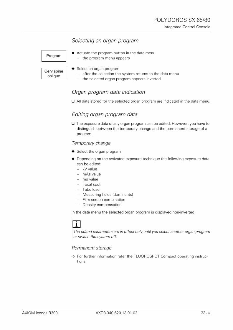
POLYDOROS SX 65/80Integrated Control Console
Selecting an organ program
◆ Actuate the program button in the data menu – the program menu appears
◆ Select an organ program– after the selection the system returns to the data menu – the selected organ program appears inverted
Organ program data indication 0
❏ All data stored for the selected organ program are indicated in the data menu.
Editing organ program data
❏ The exposure data of any organ program can be edited. However, you have to distinguish between the temporary change and the permanent storage of a program.
Temporary change 0
◆ Select the organ program
◆ Depending on the activated exposure technique the following exposure data can be edited:– kV value– mAs value– ms value – Focal spot– Tube load– Measuring fields (dominants)– Film-screen combination– Density compensation
In the data menu the selected organ program is displayed non-inverted.
Permanent storage
➩ For further information refer the FLUOROSPOT Compact operating instruc-tions
Program
Cerv spineoblique
The edited parameters are in effect only until you select another organ program or switch the system off.
AXIOM Iconos R200 AXD3-340.620.13.01.02 33 / 36
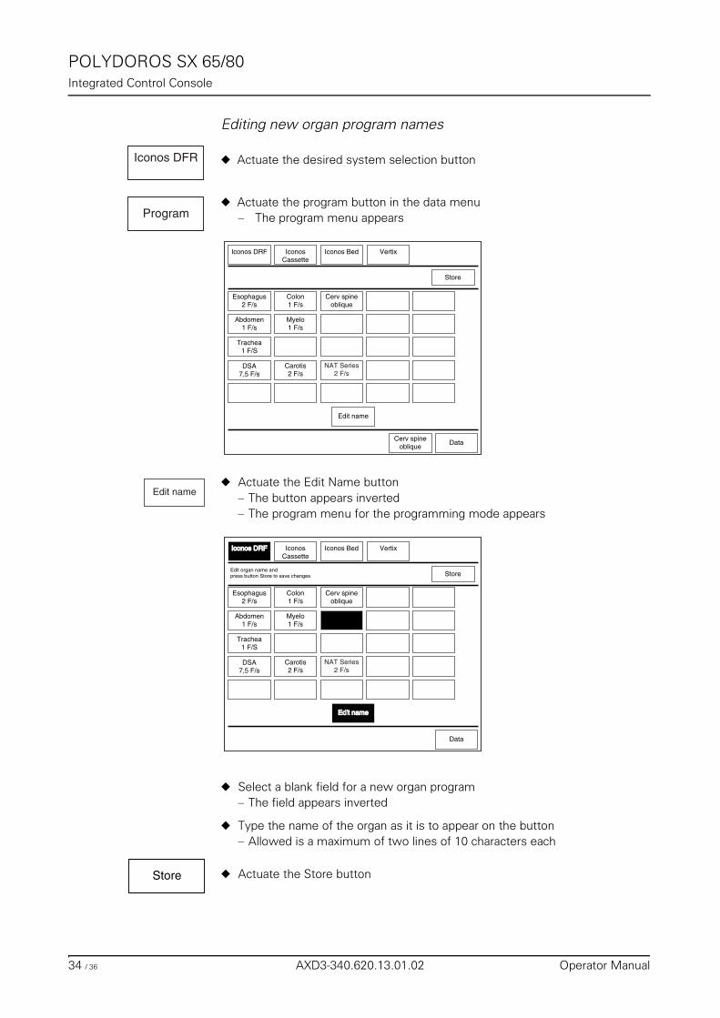
POLYDOROS SX 65/80Integrated Control Console
Editing new organ program names
◆ Actuate the desired system selection button
◆ Actuate the program button in the data menu– The program menu appears
◆ Actuate the Edit Name button– The button appears inverted – The program menu for the programming mode appears
◆ Select a blank field for a new organ program – The field appears inverted
◆ Type the name of the organ as it is to appear on the button– Allowed is a maximum of two lines of 10 characters each
◆ Actuate the Store button
Iconos DFR
Program
Trachea1 F/S
Esophagus2 F/s
DSA7,5 F/s
IconosCassette
Iconos Bed Vertix
Carotis2 F/s
Edit name
Myelo1 F/s
Colon1 F/s
Cerv spineoblique
Abdomen1 F/s
Iconos DRF
DataCerv spine
oblique
NAT Series2 F/s
Store
Edit name
Trachea1 F/S
Esophagus2 F/s
DSA7,5 F/s
IconosCassette
Iconos Bed Vertix
Carotis2 F/s
Edit nameEdit name
Myelo1 F/s
Colon1 F/s
Cerv spineoblique
Abdomen1 F/s
Iconos DRFIconos DRF
Data
NAT Series2 F/s
StoreEdit organ name andpress button Store to save changes
Store
34 / 36 AXD3-340.620.13.01.02 Operator Manual
POLYDOROS SX 65/80Integrated Control Console
Now you can edit additional organ programs.
◆ Following completion of the changes, actuate the Edit name button in the pro-gram menu for the programming mode.– Programming is now terminated and the edited program names are stored.
Actuating the data or the Edit name button takes you back to the program menu without storing the name of the organ program.
Edit name
AXIOM Iconos R200 AXD3-340.620.13.01.02 35 / 36

POLYDOROS SX 65/80Integrated Control Console
36 / 36 AXD3-340.620.13.01.02 Operator Manual
AccessoriesTable of Contents
Operator Manual
Accessories
Chapter: Preliminary Remarks
Proper use of the product .................................................................................................. 3
Safety ................................................................................................................................. 3
Orientation .......................................................................................................................... 3
Use of several accessory components ............................................................................... 4
Chapter: Standard Accessories
Grip protection strip ............................................................................................................ 5
Handgrip strip ..................................................................................................................... 6
Handgrip ............................................................................................................................. 8
Shoulder supports .............................................................................................................. 9
Footboard ......................................................................................................................... 10
Chapter: Optional Accessories
Head support .................................................................................................................... 13
Knee crutches ................................................................................................................... 15Note on biological compatibility ........................................................................................ 16
Compression belt ............................................................................................................. 17
Footboard Extension ........................................................................................................ 21
Foot restraint .................................................................................................................... 23
Cup holder ........................................................................................................................ 26
AXIOM Iconos R200 AXD3-340.620.13.01.02 1 / 54
AccessoriesTable of Contents
IV holder ........................................................................................................................... 27
Lateral cassette holder ..................................................................................................... 29Cassette holder with variable positioning ........................................................................... 29Cassette holder without variable positioning ....................................................................... 31
Foot switch assemblies for fluoroscopy and radiography ................................................ 33
Armrest ............................................................................................................................. 35
Lateral radiation shield ...................................................................................................... 36
Holder for BABIX cradles .................................................................................................. 38
BABIX cradles ................................................................................................................... 40
BABIX hanger ................................................................................................................... 42
Holder for pediatric cradle, manual ................................................................................... 43
Patient positioning mattress ............................................................................................. 43
Compression cones .......................................................................................................... 44
Radiation protection for tableside examinations ............................................................... 47
Radiation protection for the upper body ........................................................................... 49
Compensating filters ........................................................................................................ 51
Holding device for eight filters .......................................................................................... 53
Three-field templates ........................................................................................................ 54
2 / 54 AXD3-340.620.13.01.02 Operator Manual
Accessories
Preliminary Remarks
Proper use of the productThis Operator Manual describes all the accessories provided by Siemens for the ICONOS R200 system.Proper use of the accessories presupposes that the user has read and under-stood this Operator Manual in detail.In addition, the user must be thoroughly familiar with the Operator Manual for the basic system.Finally, detailed knowledge of the applicable safety regulations for the medical equipment being used is indispensable. These regulations are listed in the “Safe-ty” Register of the respective system Operator Manual.
Explanation of “proper use” consists of illustrated descriptions of attaching, us-ing and removing the accessory component.Important information will be emphasized and enclosed in a text box.Situations involving the use of accessories which could endanger the patient, the operator or the equipment will be emphasized with a WARNING.
SafetyFor reasons of safety for patients, operators and the equipment, only original accessories manufactured and sold by Siemens or Siemens-approved accesso-ries from another manufacturer may be used.
Siemens cannot assume any responsibility for accessories not approved by us.
Orientation
❏ In front of the patient table looking in the direction of the X-ray tube
❏ left is the head end of the patient table
❏ right is the foot end of the patient table
❏ frontal means the longitudinal side of the patient table close to the operating panel
❏ in back means the longitudinal side of the patient table away from the oper-ating panel
When using the accessories and to simplify the description, the following direc-tional indications shall apply in this Operator Manual with regard to the working position of the user:
AXIOM Iconos R200 AXD3-340.620.13.01.02 3 / 54
AccessoriesPreliminary Remarks
❏ turn toward the right means tighten accessory with knurled screws orlevers (clockwise)
❏ turn toward the left means remove accessory with knurled screws or levers or other fastening devices (counterclockwise)
Example:
◆ Turn both knurled screws toward the left
◆ Push the grip protection strip on the head end into both accessory rails
◆ Turn both knurled screws toward the right
◆ Check that the grip protection strip is seated securely
Use of several accessory componentsThis document describes the use of a single accessory component in each chap-ter text.
If you need to work with several components during an examination, e.g. com-pression belt and shoulder supports, these components must be attached and re-moved in the correct sequence because most1 accessory components are attached to the patient table using the accessory rails.
Example:
❏ Grip protection strip and footboard are already attached to the patient table.
❏ You need the shoulder supports in addition because they will be helpful for the examination.
◆ First, you must remove the grip protection strip as described in these instruc-tions.
◆ Then position the patient on the table.
◆ Next attach the shoulder supports.
◆ Next push the grip protection strip back into the accessory rails and secure it.
◆ Check that all accessory components are securely attached.
1 Exceptions: compression belt, lateral cassette holder, arm rest
4 / 54 AXD3-340.620.13.01.02 Operator Manual
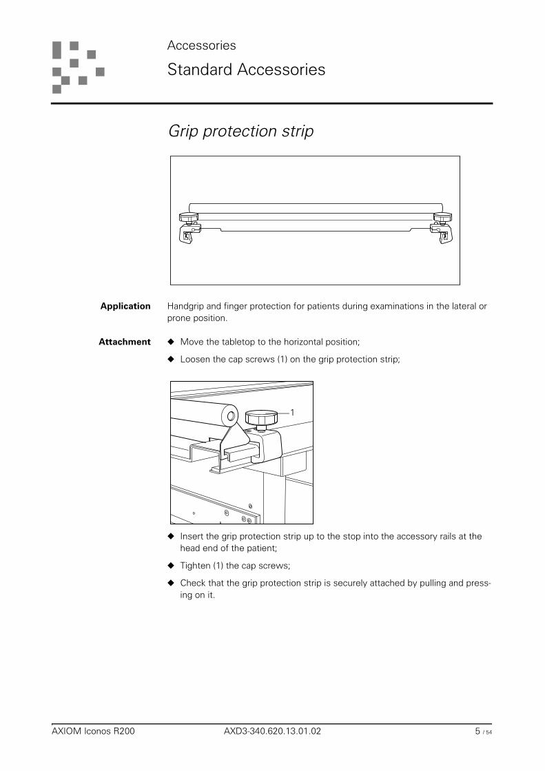
Accessories
Standard Accessories
Grip protection strip
Application Handgrip and finger protection for patients during examinations in the lateral or prone position.
Attachment ◆ Move the tabletop to the horizontal position;
◆ Loosen the cap screws (1) on the grip protection strip;
◆ Insert the grip protection strip up to the stop into the accessory rails at the head end of the patient;
◆ Tighten (1) the cap screws;
◆ Check that the grip protection strip is securely attached by pulling and press-ing on it.
1
AXIOM Iconos R200 AXD3-340.620.13.01.02 5 / 54
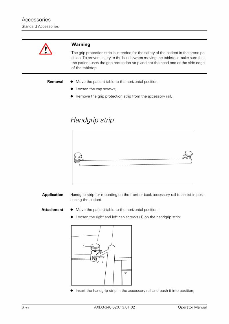
AccessoriesStandard Accessories
Removal ◆ Move the patient table to the horizontal position;
◆ Loosen the cap screws;
◆ Remove the grip protection strip from the accessory rail.
Handgrip strip
Application Handgrip strip for mounting on the front or back accessory rail to assist in posi-tioning the patient
Attachment ◆ Move the patient table to the horizontal position;
◆ Loosen the right and left cap screws (1) on the handgrip strip;
◆ Insert the handgrip strip in the accessory rail and push it into position;
Warning
The grip protection strip is intended for the safety of the patient in the prone po-sition. To prevent injury to the hands when moving the tabletop, make sure that the patient uses the grip protection strip and not the head end or the side edge of the tabletop.
1
6 / 54 AXD3-340.620.13.01.02 Operator Manual
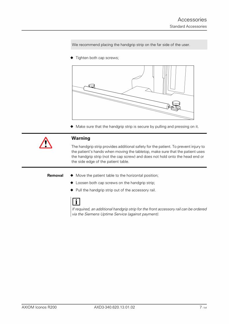
AccessoriesStandard Accessories
◆ Tighten both cap screws;
◆ Make sure that the handgrip strip is secure by pulling and pressing on it.
Removal ◆ Move the patient table to the horizontal position;
◆ Loosen both cap screws on the handgrip strip;
◆ Pull the handgrip strip out of the accessory rail.
We recommend placing the handgrip strip on the far side of the user.
Warning
The handgrip strip provides additional safety for the patient. To prevent injury to the patient’s hands when moving the tabletop, make sure that the patient uses the handgrip strip (not the cap screw) and does not hold onto the head end or the side edge of the patient table.
If required, an additional handgrip strip for the front accessory rail can be ordered via the Siemens Uptime Service (against payment).
AXIOM Iconos R200 AXD3-340.620.13.01.02 7 / 54
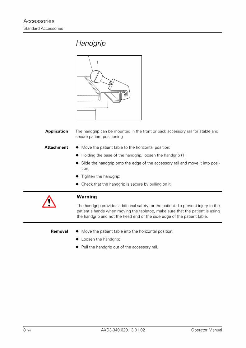
AccessoriesStandard Accessories
Handgrip
Application The handgrip can be mounted in the front or back accessory rail for stable and secure patient positioning
Attachment ◆ Move the patient table to the horizontal position;
◆ Holding the base of the handgrip, loosen the handgrip (1);
◆ Slide the handgrip onto the edge of the accessory rail and move it into posi-tion;
◆ Tighten the handgrip;
◆ Check that the handgrip is secure by pulling on it.
Removal ◆ Move the patient table into the horizontal position;
◆ Loosen the handgrip;
◆ Pull the handgrip out of the accessory rail.
1
Warning
The handgrip provides additional safety for the patient. To prevent injury to the patient’s hands when moving the tabletop, make sure that the patient is using the handgrip and not the head end or the side edge of the patient table.
8 / 54 AXD3-340.620.13.01.02 Operator Manual
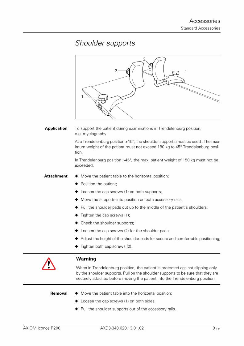
AccessoriesStandard Accessories
Shoulder supports
Application To support the patient during examinations in Trendelenburg position,e.g. myelography
At a Trendelenburg position >15°, the shoulder supports must be used . The max-imum weight of the patient must not exceed 180 kg to 45° Trendelenburg posi-tion.
In Trendelenburg position >45°, the max. patient weight of 150 kg must not be exceeded.
Attachment ◆ Move the patient table to the horizontal position;
◆ Position the patient;
◆ Loosen the cap screws (1) on both supports;
◆ Move the supports into position on both accessory rails;
◆ Pull the shoulder pads out up to the middle of the patient’s shoulders;
◆ Tighten the cap screws (1);
◆ Check the shoulder supports;
◆ Loosen the cap screws (2) for the shoulder pads;
◆ Adjust the height of the shoulder pads for secure and comfortable positioning;
◆ Tighten both cap screws (2).
Removal ◆ Move the patient table into the horizontal position;
◆ Loosen the cap screws (1) on both sides;
◆ Pull the shoulder supports out of the accessory rails.
2
1
2
1
Warning
When in Trendelenburg position, the patient is protected against slipping only by the shoulder supports. Pull on the shoulder supports to be sure that they are securely attached before moving the patient into the Trendelenburg position.
AXIOM Iconos R200 AXD3-340.620.13.01.02 9 / 54
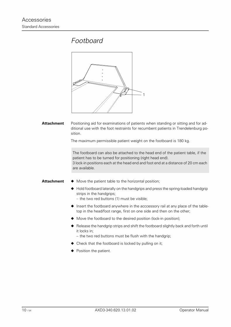
AccessoriesStandard Accessories
Footboard
Attachment Positioning aid for examinations of patients when standing or sitting and for ad-ditional use with the foot restraints for recumbent patients in Trendelenburg po-sition.
The maximum permissible patient weight on the footboard is 180 kg.
Attachment ◆ Move the patient table to the horizontal position;
◆ Hold footboard laterally on the handgrips and press the spring-loaded handgrip strips in the handgrips;– the two red buttons (1) must be visible;
◆ Insert the footboard anywhere in the acccessory rail at any place of the table-top in the head/foot range, first on one side and then on the other;
◆ Move the footboard to the desired position (lock-in position);
◆ Release the handgrip strips and shift the footboard slightly back and forth until it locks in;– the two red buttons must be flush with the handgrip;
◆ Check that the footboard is locked by pulling on it;
◆ Position the patient.
1
The footboard can also be attached to the head end of the patient table, if the patient has to be turned for positioning (right head end).3 lock-in positions each at the head end and foot end at a distance of 20 cm each are available.
10 / 54 AXD3-340.620.13.01.02 Operator Manual
AccessoriesStandard Accessories
Adjustment ◆ Press the spring-loaded handgrip strips in the handgrips;– the two red buttons must be visible;
◆ Move the footboard to the desired position (lock-in position);
◆ Release the handgrip strips and shift the footboard slightly back and forth until it locks in;– the two red buttons must be flush with the handgrip;
Removal ◆ Move the patient table to the horizontal position;
◆ Press the spring-loaded handgrip strips in the handgrips;– the two red buttons must be visibible;
◆ Lift the footboard first on one side and remove from the accessory rail;
◆ Remove other side of the footboard from the accessory rail.
Maintenance note In order to prevent influx of contrast medium into the sockets, the pedal must be covered with absorbent fleece material.
Warning
Be sure to check that the footboard has locked into position before allowing pa-tients to sit or stand on it. If you want to tilt the patient table from the horizontal position to the Trendelenburg position, you must secure the patient with the shoulder supports or the foot restraints at 15o. In case of a Trendelenburg posi-tion >40°, the foot restraints must be used in addition to the shoulder supports. Make sure that patients standing on the footboard hold onto the handgrip and the handgrip strip. For additional safety, use the compression belt for frail or very unsteady patients.
Warning
The footboard may only be unlocked, adjusted or removed when the table is in the horizontal position. In all other system positions, the footboard could fall off and present a high risk of accidents.
AXIOM Iconos R200 AXD3-340.620.13.01.02 11 / 54

AccessoriesStandard Accessories
12 / 54 AXD3-340.620.13.01.02 Operator Manual
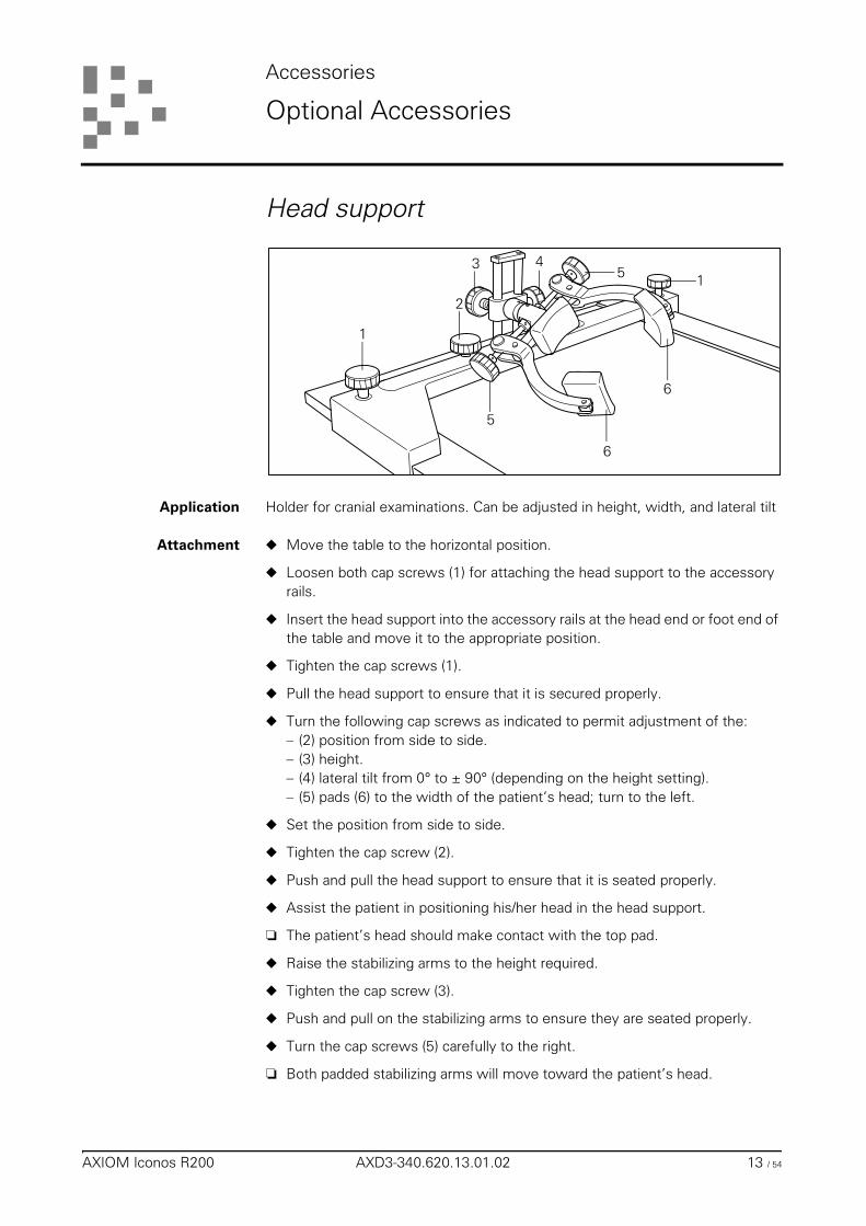
Accessories
Optional Accessories
Head support
Application Holder for cranial examinations. Can be adjusted in height, width, and lateral tilt
Attachment ◆ Move the table to the horizontal position.
◆ Loosen both cap screws (1) for attaching the head support to the accessory rails.
◆ Insert the head support into the accessory rails at the head end or foot end of the table and move it to the appropriate position.
◆ Tighten the cap screws (1).
◆ Pull the head support to ensure that it is secured properly.
◆ Turn the following cap screws as indicated to permit adjustment of the:– (2) position from side to side.– (3) height.– (4) lateral tilt from 0° to ± 90° (depending on the height setting).– (5) pads (6) to the width of the patient’s head; turn to the left.
◆ Set the position from side to side.
◆ Tighten the cap screw (2).
◆ Push and pull the head support to ensure that it is seated properly.
◆ Assist the patient in positioning his/her head in the head support.
❏ The patient’s head should make contact with the top pad.
◆ Raise the stabilizing arms to the height required.
◆ Tighten the cap screw (3).
◆ Push and pull on the stabilizing arms to ensure they are seated properly.
◆ Turn the cap screws (5) carefully to the right.
❏ Both padded stabilizing arms will move toward the patient’s head.
2
1
5
1
3
5
154
11
6
6
AXIOM Iconos R200 AXD3-340.620.13.01.02 13 / 54
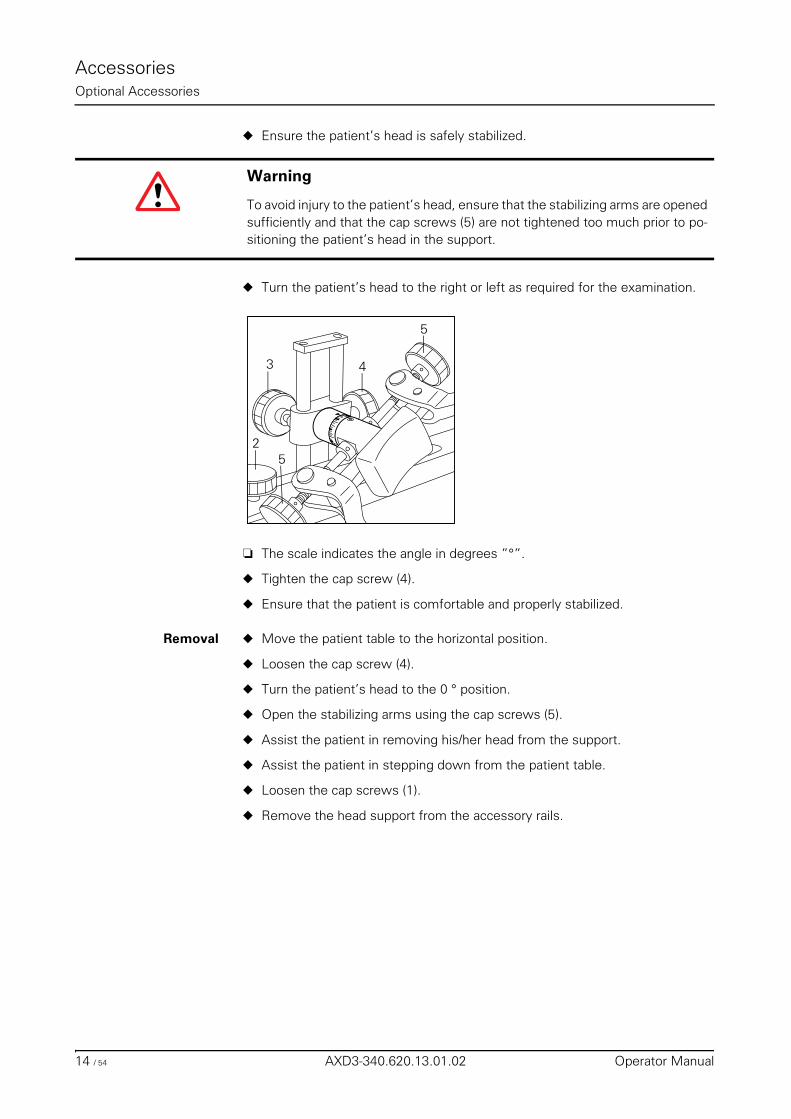
AccessoriesOptional Accessories
◆ Ensure the patient’s head is safely stabilized.
◆ Turn the patient’s head to the right or left as required for the examination.
❏ The scale indicates the angle in degrees ”°”.
◆ Tighten the cap screw (4).
◆ Ensure that the patient is comfortable and properly stabilized.
Removal ◆ Move the patient table to the horizontal position.
◆ Loosen the cap screw (4).
◆ Turn the patient’s head to the 0 ° position.
◆ Open the stabilizing arms using the cap screws (5).
◆ Assist the patient in removing his/her head from the support.
◆ Assist the patient in stepping down from the patient table.
◆ Loosen the cap screws (1).
◆ Remove the head support from the accessory rails.
Warning
To avoid injury to the patient’s head, ensure that the stabilizing arms are opened sufficiently and that the cap screws (5) are not tightened too much prior to po-sitioning the patient’s head in the support.
2
3 4
5
5
14 / 54 AXD3-340.620.13.01.02 Operator Manual
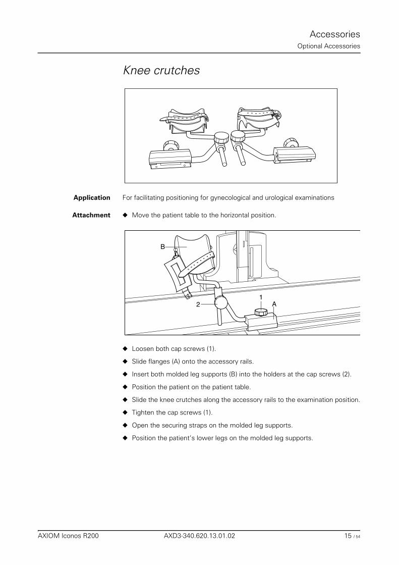
AccessoriesOptional Accessories
Knee crutches
Application For facilitating positioning for gynecological and urological examinations
Attachment ◆ Move the patient table to the horizontal position.
◆ Loosen both cap screws (1).
◆ Slide flanges (A) onto the accessory rails.
◆ Insert both molded leg supports (B) into the holders at the cap screws (2).
◆ Position the patient on the patient table.
◆ Slide the knee crutches along the accessory rails to the examination position.
◆ Tighten the cap screws (1).
◆ Open the securing straps on the molded leg supports.
◆ Position the patient’s lower legs on the molded leg supports.
21
A
B
AXIOM Iconos R200 AXD3-340.620.13.01.02 15 / 54
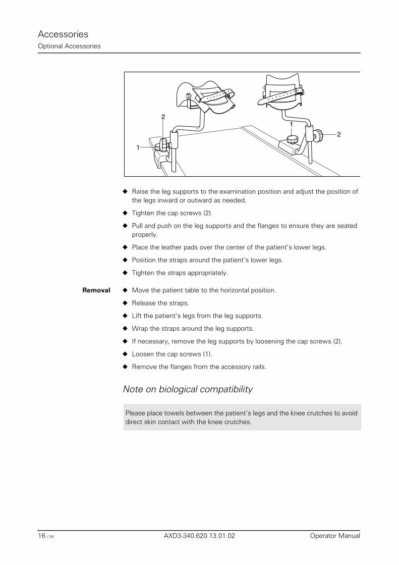
AccessoriesOptional Accessories
◆ Raise the leg supports to the examination position and adjust the position of the legs inward or outward as needed.
◆ Tighten the cap screws (2).
◆ Pull and push on the leg supports and the flanges to ensure they are seated properly.
◆ Place the leather pads over the center of the patient’s lower legs.
◆ Position the straps around the patient’s lower legs.
◆ Tighten the straps appropriately.
Removal ◆ Move the patient table to the horizontal position.
◆ Release the straps.
◆ Lift the patient’s legs from the leg supports.
◆ Wrap the straps around the leg supports.
◆ If necessary, remove the leg supports by loosening the cap screws (2).
◆ Loosen the cap screws (1).
◆ Remove the flanges from the accessory rails.
Note on biological compatibility
2
1
2
1
Please place towels between the patient’s legs and the knee crutches to avoid direct skin contact with the knee crutches.
16 / 54 AXD3-340.620.13.01.02 Operator Manual
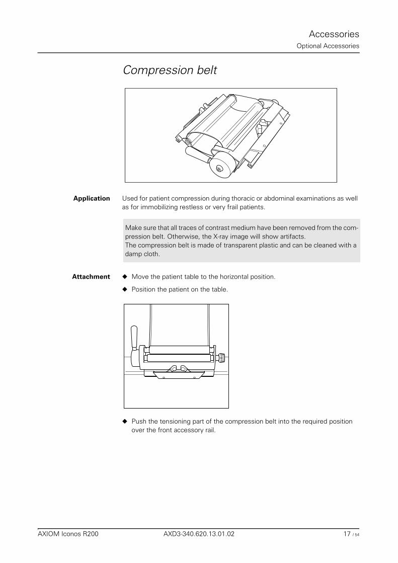
AccessoriesOptional Accessories
Compression belt
Application Used for patient compression during thoracic or abdominal examinations as well as for immobilizing restless or very frail patients.
Attachment ◆ Move the patient table to the horizontal position.
◆ Position the patient on the table.
◆ Push the tensioning part of the compression belt into the required position over the front accessory rail.
Make sure that all traces of contrast medium have been removed from the com-pression belt. Otherwise, the X-ray image will show artifacts.The compression belt is made of transparent plastic and can be cleaned with a damp cloth.
AXIOM Iconos R200 AXD3-340.620.13.01.02 17 / 54
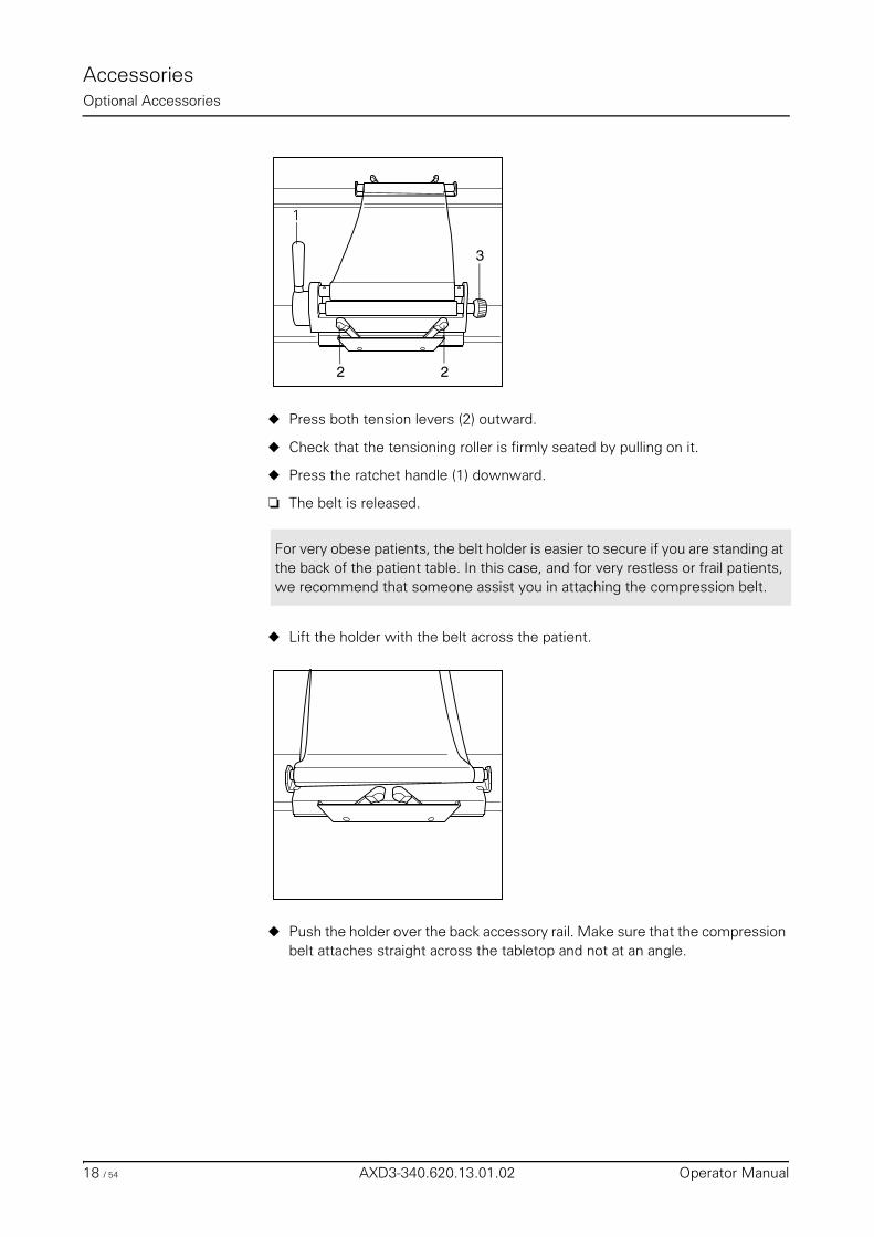
AccessoriesOptional Accessories
◆ Press both tension levers (2) outward.
◆ Check that the tensioning roller is firmly seated by pulling on it.
◆ Press the ratchet handle (1) downward.
❏ The belt is released.
◆ Lift the holder with the belt across the patient.
◆ Push the holder over the back accessory rail. Make sure that the compression belt attaches straight across the tabletop and not at an angle.
22
3
1
For very obese patients, the belt holder is easier to secure if you are standing at the back of the patient table. In this case, and for very restless or frail patients, we recommend that someone assist you in attaching the compression belt.
18 / 54 AXD3-340.620.13.01.02 Operator Manual
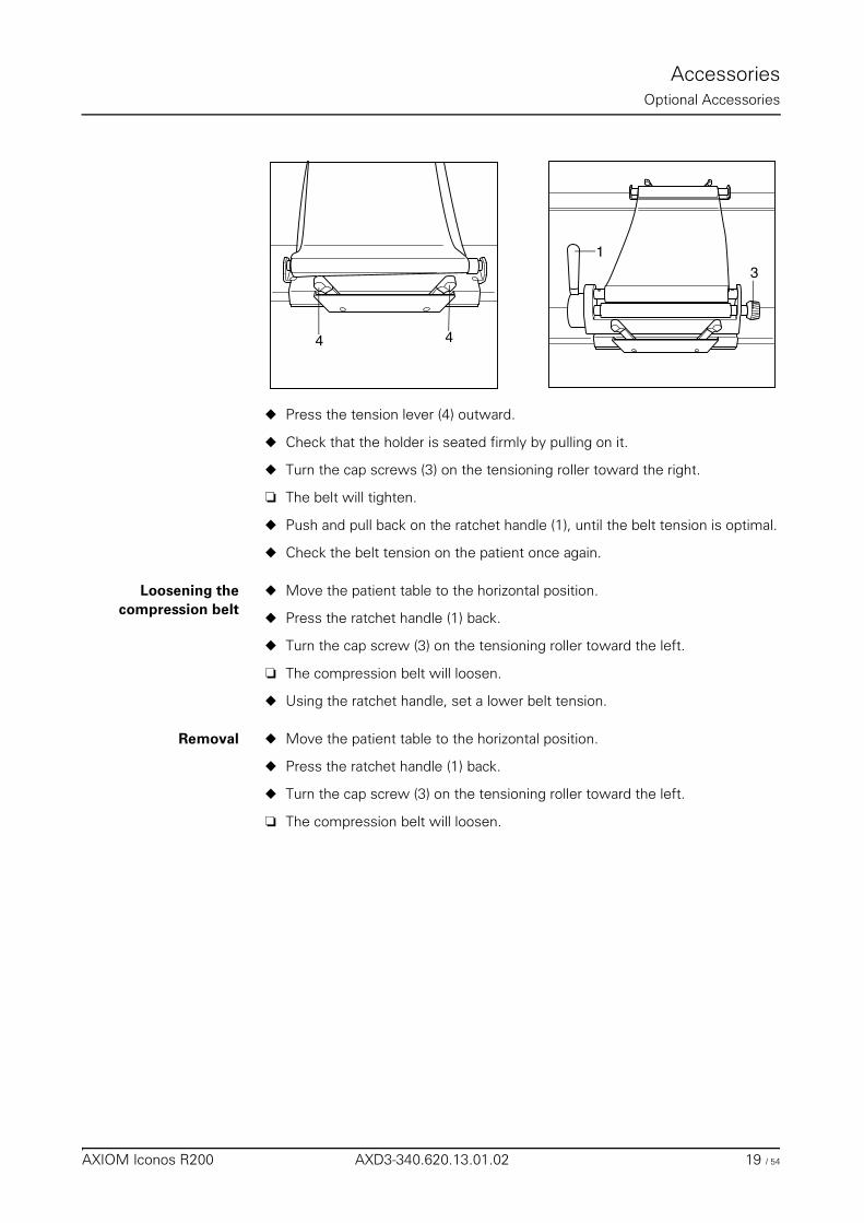
AccessoriesOptional Accessories
◆ Press the tension lever (4) outward.
◆ Check that the holder is seated firmly by pulling on it.
◆ Turn the cap screws (3) on the tensioning roller toward the right.
❏ The belt will tighten.
◆ Push and pull back on the ratchet handle (1), until the belt tension is optimal.
◆ Check the belt tension on the patient once again.
Loosening thecompression belt
◆ Move the patient table to the horizontal position.
◆ Press the ratchet handle (1) back.
◆ Turn the cap screw (3) on the tensioning roller toward the left.
❏ The compression belt will loosen.
◆ Using the ratchet handle, set a lower belt tension.
Removal ◆ Move the patient table to the horizontal position.
◆ Press the ratchet handle (1) back.
◆ Turn the cap screw (3) on the tensioning roller toward the left.
❏ The compression belt will loosen.
4 4
3
1
AXIOM Iconos R200 AXD3-340.620.13.01.02 19 / 54
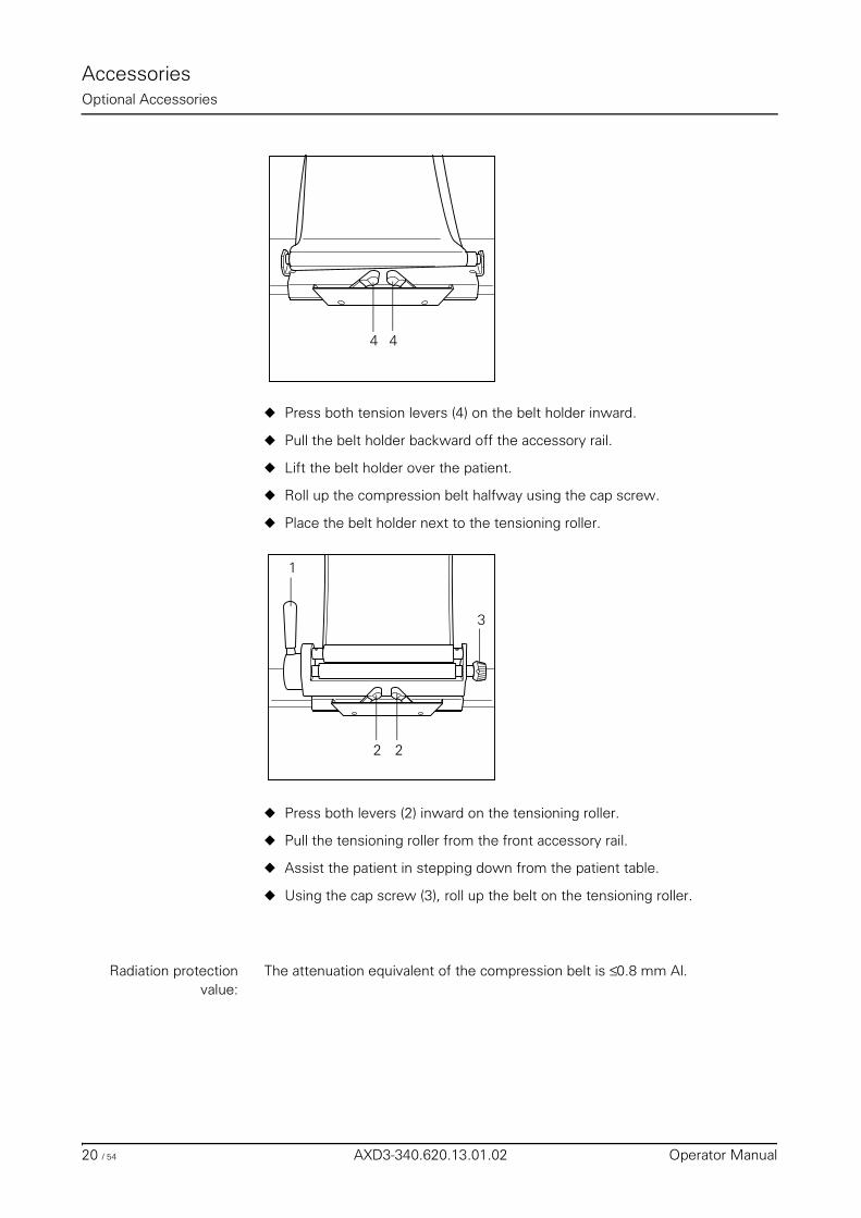
AccessoriesOptional Accessories
◆ Press both tension levers (4) on the belt holder inward.
◆ Pull the belt holder backward off the accessory rail.
◆ Lift the belt holder over the patient.
◆ Roll up the compression belt halfway using the cap screw.
◆ Place the belt holder next to the tensioning roller.
◆ Press both levers (2) inward on the tensioning roller.
◆ Pull the tensioning roller from the front accessory rail.
◆ Assist the patient in stepping down from the patient table.
◆ Using the cap screw (3), roll up the belt on the tensioning roller.
Radiation protectionvalue:
The attenuation equivalent of the compression belt is ≤ 0.8 mm Al.
44
22
1
3
20 / 54 AXD3-340.620.13.01.02 Operator Manual
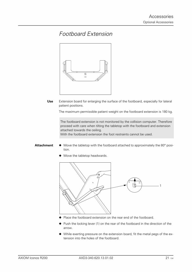
AccessoriesOptional Accessories
Footboard Extension
Use Extension board for enlarging the surface of the footboard, especially for lateral patient positions.
The maximum permissible patient weight on the footboard extension is 180 kg.
Attachment ◆ Move the tabletop with the footboard attached to approximately the 80° posi-tion.
◆ Move the tabletop headwards.
◆ Place the footboard extension on the rear end of the footboard.
◆ Push the locking lever (1) on the rear of the footboard in the direction of the arrow.
◆ While exerting pressure on the extension board, fit the metal pegs of the ex-tension into the holes of the footboard.
The footboard extension is not monitored by the collision computer. Therefore proceed with care when tilting the tabletop with the footboard and extension attached towards the ceiling. With the footboard extension the foot restraints cannot be used.
1
AXIOM Iconos R200 AXD3-340.620.13.01.02 21 / 54
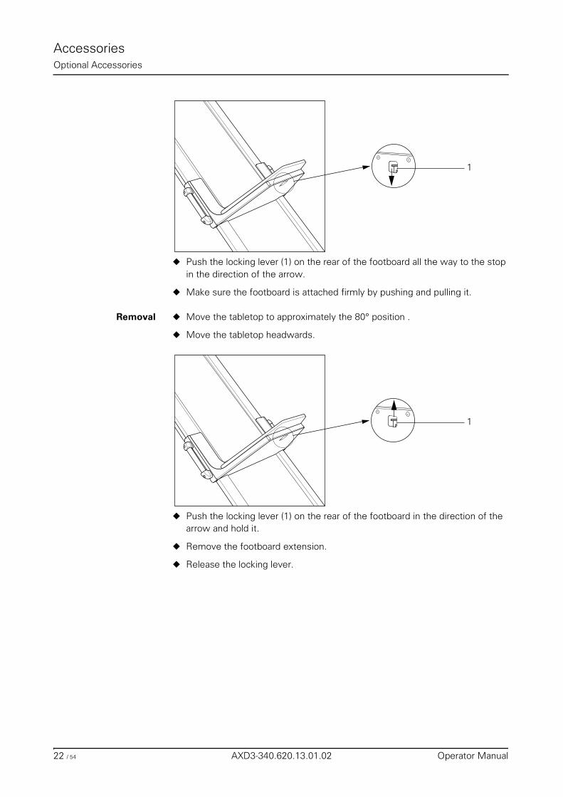
AccessoriesOptional Accessories
◆ Push the locking lever (1) on the rear of the footboard all the way to the stop in the direction of the arrow.
◆ Make sure the footboard is attached firmly by pushing and pulling it.
Removal ◆ Move the tabletop to approximately the 80° position .
◆ Move the tabletop headwards.
◆ Push the locking lever (1) on the rear of the footboard in the direction of the arrow and hold it.
◆ Remove the footboard extension.
◆ Release the locking lever.
1
1
22 / 54 AXD3-340.620.13.01.02 Operator Manual
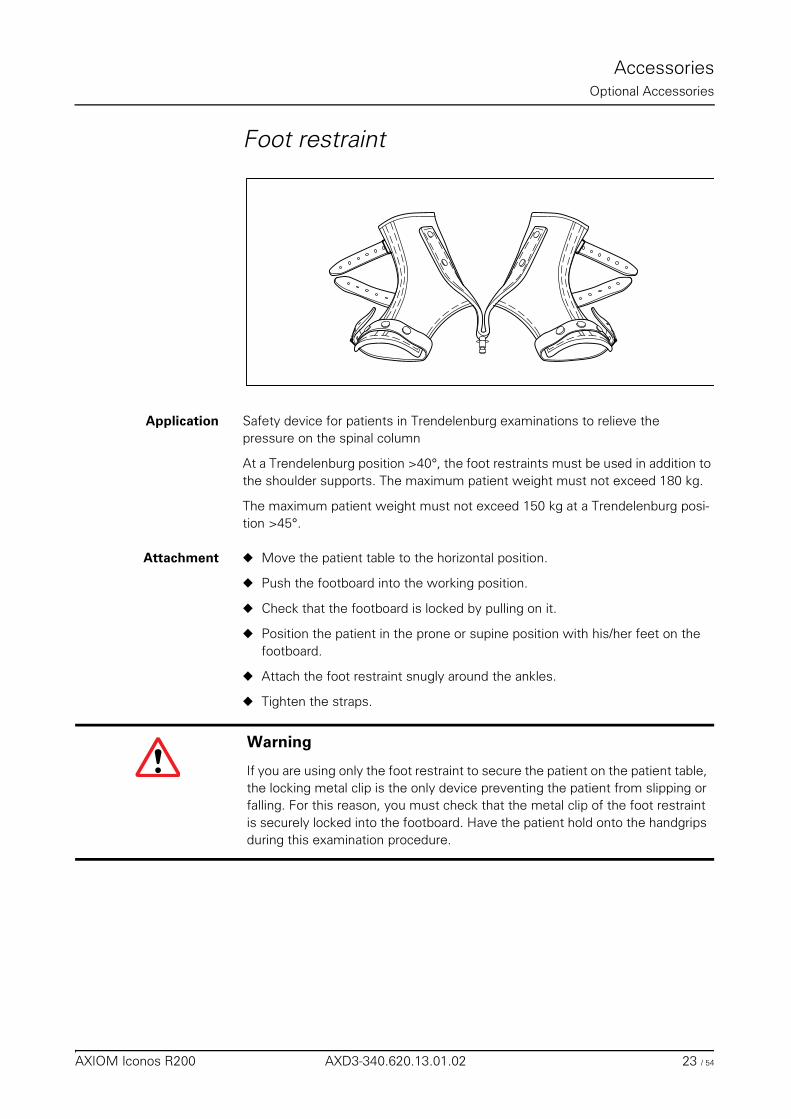
AccessoriesOptional Accessories
Foot restraint
Application Safety device for patients in Trendelenburg examinations to relieve the pressure on the spinal column
At a Trendelenburg position >40°, the foot restraints must be used in addition to the shoulder supports. The maximum patient weight must not exceed 180 kg.
The maximum patient weight must not exceed 150 kg at a Trendelenburg posi-tion >45°.
Attachment ◆ Move the patient table to the horizontal position.
◆ Push the footboard into the working position.
◆ Check that the footboard is locked by pulling on it.
◆ Position the patient in the prone or supine position with his/her feet on the footboard.
◆ Attach the foot restraint snugly around the ankles.
◆ Tighten the straps.
Warning
If you are using only the foot restraint to secure the patient on the patient table, the locking metal clip is the only device preventing the patient from slipping or falling. For this reason, you must check that the metal clip of the foot restraint is securely locked into the footboard. Have the patient hold onto the handgrips during this examination procedure.
AXIOM Iconos R200 AXD3-340.620.13.01.02 23 / 54
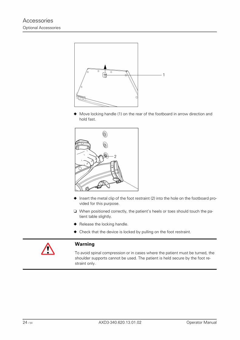
AccessoriesOptional Accessories
◆ Move locking handle (1) on the rear of the footboard in arrow direction and hold fast.
◆ Insert the metal clip of the foot restraint (2) into the hole on the footboard pro-vided for this purpose.
❏ When positioned correctly, the patient’s heels or toes should touch the pa-tient table slightly.
◆ Release the locking handle.
◆ Check that the device is locked by pulling on the foot restraint.
1
2
Warning
To avoid spinal compression or in cases where the patient must be turned, the shoulder supports cannot be used. The patient is held secure by the foot re-straint only.
24 / 54 AXD3-340.620.13.01.02 Operator Manual
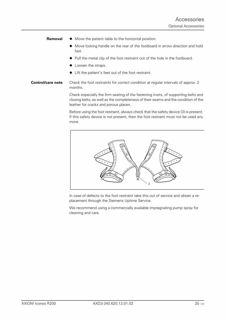
AccessoriesOptional Accessories
Removal ◆ Move the patient table to the horizontal position.
◆ Move locking handle on the rear of the footboard in arrow direction and hold fast.
◆ Pull the metal clip of the foot restraint out of the hole in the footboard.
◆ Loosen the straps.
◆ Lift the patient’s feet out of the foot restraint.
Control/care note Check the foot restraints for correct condition at regular intervals of approx. 2 months.
Check especially the firm seating of the fastening rivets, of supporting belts and closing belts, as well as the completeness of their seams and the condition of the leather for cracks and porous places.
Before using the foot restraint, always check that the safety device (3) is present. If this safety device is not present, then the foot restraint must not be used any more.
In case of defects to the foot restraint take this out of service and obtain a re-placement through the Siemens Uptime Service.
We recommend using a commercially available impregnating pump spray for cleaning and care.
3
AXIOM Iconos R200 AXD3-340.620.13.01.02 25 / 54
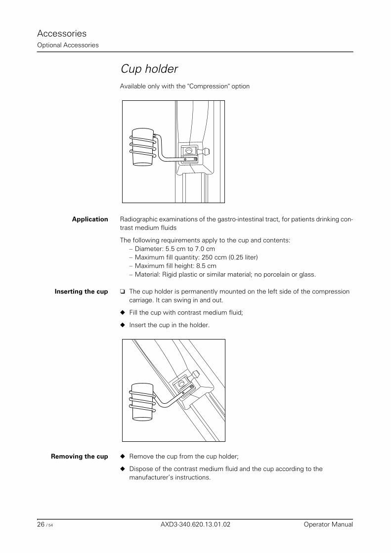
AccessoriesOptional Accessories
Cup holderAvailable only with the "Compression" option
Application Radiographic examinations of the gastro-intestinal tract, for patients drinking con-trast medium fluids
The following requirements apply to the cup and contents:– Diameter: 5.5 cm to 7.0 cm– Maximum fill quantity: 250 ccm (0.25 liter)– Maximum fill height: 8.5 cm– Material: Rigid plastic or similar material; no porcelain or glass.
Inserting the cup ❏ The cup holder is permanently mounted on the left side of the compression carriage. It can swing in and out.
◆ Fill the cup with contrast medium fluid;
◆ Insert the cup in the holder.
Removing the cup ◆ Remove the cup from the cup holder;
◆ Dispose of the contrast medium fluid and the cup according to the manufacturer’s instructions.
26 / 54 AXD3-340.620.13.01.02 Operator Manual
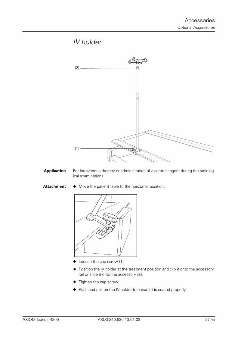
AccessoriesOptional Accessories
IV holder
Application For intravenous therapy or administration of a contrast agent during the radiolog-ical examinations
Attachment ◆ Move the patient table to the horizontal position.;
◆ Loosen the cap screw (1).
◆ Position the IV holder at the treatment position and clip it onto the accessory rail or slide it onto the accessory rail.
◆ Tighten the cap screw.
◆ Push and pull on the IV holder to ensure it is seated properly.
(2)
(1)
1
AXIOM Iconos R200 AXD3-340.620.13.01.02 27 / 54
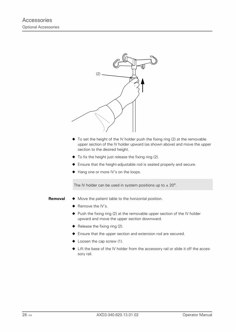
AccessoriesOptional Accessories
◆ To set the height of the IV holder push the fixing ring (2) at the removable upper section of the IV holder upward (as shown above) and move the upper section to the desired height.
◆ To fix the height just release the fixing ring (2).
◆ Ensure that the height-adjustable rod is seated properly and secure.
◆ Hang one or more IV’s on the loops.
Removal ◆ Move the patient table to the horizontal position.
◆ Remove the IV’s.
◆ Push the fixing ring (2) at the removable upper section of the IV holder upward and move the upper section downward.
◆ Release the fixing ring (2).
◆ Ensure that the upper section and extension rod are secured.
◆ Loosen the cap screw (1).
◆ Lift the base of the IV holder from the accessory rail or slide it off the acces-sory rail.
(2)
The IV holder can be used in system positions up to ± 20o.
28 / 54 AXD3-340.620.13.01.02 Operator Manual
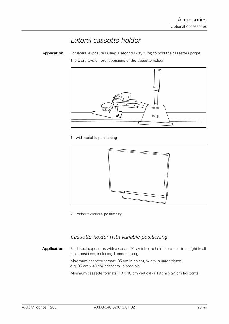
AccessoriesOptional Accessories
Lateral cassette holder
Application For lateral exposures using a second X-ray tube; to hold the cassette upright
There are two different versions of the cassette holder:
1. with variable positioning
2. without variable positioning
Cassette holder with variable positioning
Application For lateral exposures with a second X-ray tube; to hold the cassette upright in all table positions, including Trendelenburg.
Maximum cassette format: 35 cm in height, width is unrestricted, e.g. 35 cm x 43 cm horizontal is possible.
Minimum cassette formats: 13 x 18 cm vertical or 18 cm x 24 cm horizontal.
AXIOM Iconos R200 AXD3-340.620.13.01.02 29 / 54
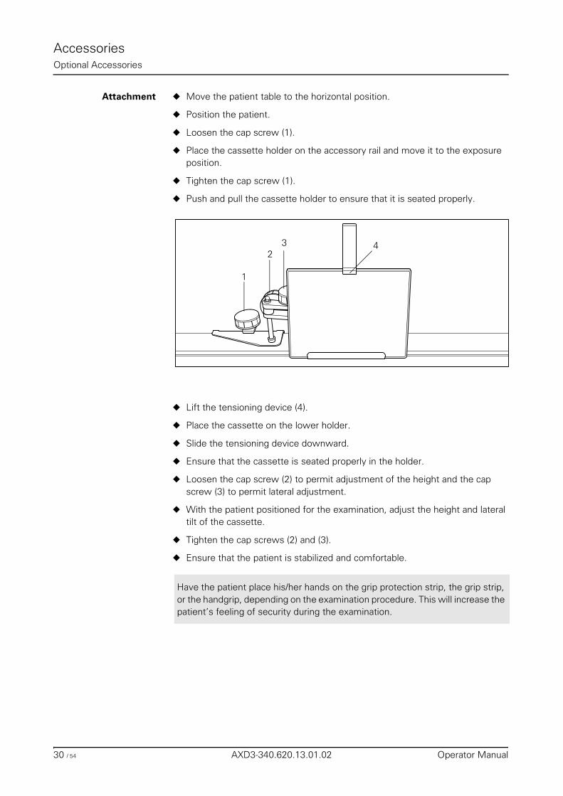
AccessoriesOptional Accessories
Attachment ◆ Move the patient table to the horizontal position.
◆ Position the patient.
◆ Loosen the cap screw (1).
◆ Place the cassette holder on the accessory rail and move it to the exposure position.
◆ Tighten the cap screw (1).
◆ Push and pull the cassette holder to ensure that it is seated properly.
◆ Lift the tensioning device (4).
◆ Place the cassette on the lower holder.
◆ Slide the tensioning device downward.
◆ Ensure that the cassette is seated properly in the holder.
◆ Loosen the cap screw (2) to permit adjustment of the height and the cap screw (3) to permit lateral adjustment.
◆ With the patient positioned for the examination, adjust the height and lateral tilt of the cassette.
◆ Tighten the cap screws (2) and (3).
◆ Ensure that the patient is stabilized and comfortable.
432
1
Have the patient place his/her hands on the grip protection strip, the grip strip, or the handgrip, depending on the examination procedure. This will increase the patient’s feeling of security during the examination.
30 / 54 AXD3-340.620.13.01.02 Operator Manual
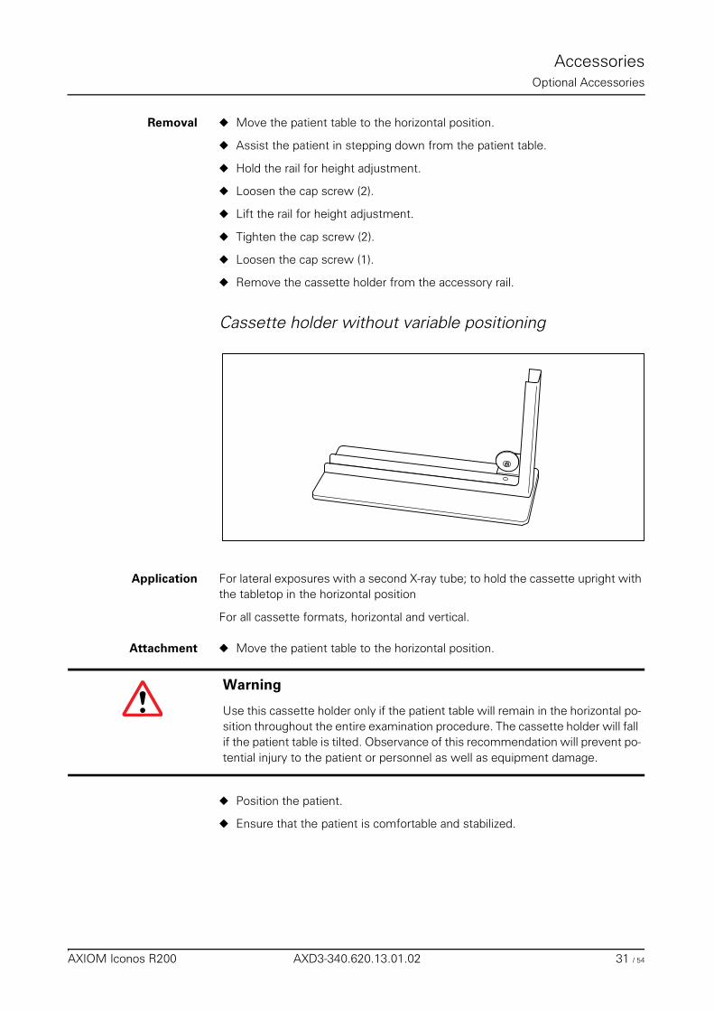
AccessoriesOptional Accessories
Removal ◆ Move the patient table to the horizontal position.
◆ Assist the patient in stepping down from the patient table.
◆ Hold the rail for height adjustment.
◆ Loosen the cap screw (2).
◆ Lift the rail for height adjustment.
◆ Tighten the cap screw (2).
◆ Loosen the cap screw (1).
◆ Remove the cassette holder from the accessory rail.
Cassette holder without variable positioning
Application For lateral exposures with a second X-ray tube; to hold the cassette upright with the tabletop in the horizontal position
For all cassette formats, horizontal and vertical.
Attachment ◆ Move the patient table to the horizontal position.
◆ Position the patient.
◆ Ensure that the patient is comfortable and stabilized.
Warning
Use this cassette holder only if the patient table will remain in the horizontal po-sition throughout the entire examination procedure. The cassette holder will fall if the patient table is tilted. Observance of this recommendation will prevent po-tential injury to the patient or personnel as well as equipment damage.
AXIOM Iconos R200 AXD3-340.620.13.01.02 31 / 54
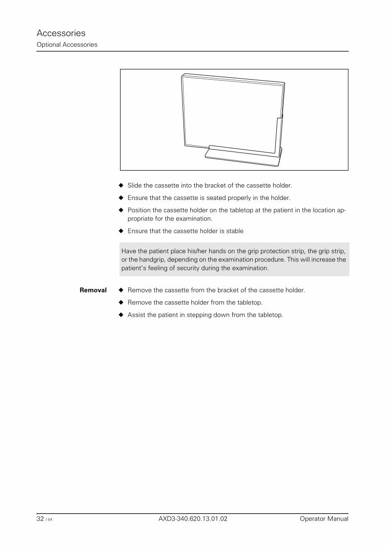
AccessoriesOptional Accessories
◆ Slide the cassette into the bracket of the cassette holder.
◆ Ensure that the cassette is seated properly in the holder.
◆ Position the cassette holder on the tabletop at the patient in the location ap-propriate for the examination.
◆ Ensure that the cassette holder is stable
Removal ◆ Remove the cassette from the bracket of the cassette holder.
◆ Remove the cassette holder from the tabletop.
◆ Assist the patient in stepping down from the tabletop.
Have the patient place his/her hands on the grip protection strip, the grip strip, or the handgrip, depending on the examination procedure. This will increase the patient’s feeling of security during the examination.
32 / 54 AXD3-340.620.13.01.02 Operator Manual
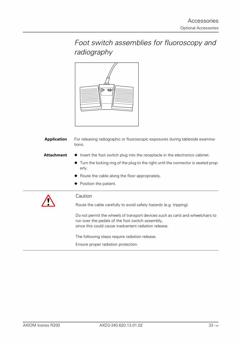
AccessoriesOptional Accessories
Foot switch assemblies for fluoroscopy and radiography
Application For releasing radiographic or fluoroscopic exposures during tableside examina-tions.
Attachment ◆ Insert the foot switch plug into the receptacle in the electronics cabinet.
◆ Turn the locking ring of the plug to the right until the connector is seated prop-erly.
◆ Route the cable along the floor appropriately.
◆ Position the patient.
Caution
Route the cable carefully to avoid safety hazards (e.g. tripping).
Do not permit the wheels of transport devices such as carts and wheelchairs to run over the pedals of the foot switch assembly,since this could cause inadvertent radiation release.
The following steps require radiation release.
Ensure proper radiation protection.
AXIOM Iconos R200 AXD3-340.620.13.01.02 33 / 54
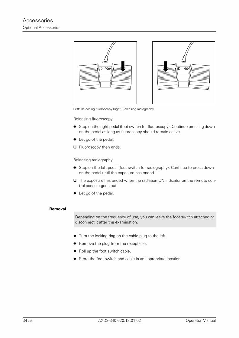
AccessoriesOptional Accessories
Left: Releasing fluoroscopy Right: Releasing radiography
Releasing fluoroscopy
◆ Step on the right pedal (foot switch for fluoroscopy). Continue pressing down on the pedal as long as fluoroscopy should remain active.
◆ Let go of the pedal.
❏ Fluoroscopy then ends.
Releasing radiography
◆ Step on the left pedal (foot switch for radiography). Continue to press down on the pedal until the exposure has ended.
❏ The exposure has ended when the radiation ON indicator on the remote con-trol console goes out.
◆ Let go of the pedal.
Removal
◆ Turn the locking ring on the cable plug to the left.
◆ Remove the plug from the receptacle.
◆ Roll up the foot switch cable.
◆ Store the foot switch and cable in an appropriate location.
Depending on the frequency of use, you can leave the foot switch attached or disconnect it after the examination.
34 / 54 AXD3-340.620.13.01.02 Operator Manual
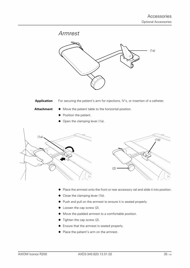
AccessoriesOptional Accessories
Armrest
Application For securing the patient’s arm for injections, IV’s, or insertion of a catheter.
Attachment ◆ Move the patient table to the horizontal position.
◆ Position the patient.
◆ Open the clamping lever (1a).
◆ Place the armrest onto the front or rear accessory rail and slide it into position.
◆ Close the clamping lever (1b).
◆ Push and pull on the armrest to ensure it is seated properly.
◆ Loosen the cap screw (2).
◆ Move the padded armrest to a comfortable position.
◆ Tighten the cap screw (2).
◆ Ensure that the armrest is seated properly.
◆ Place the patient’s arm on the armrest.
(1a)
(1a)(1b)
(2)
AXIOM Iconos R200 AXD3-340.620.13.01.02 35 / 54
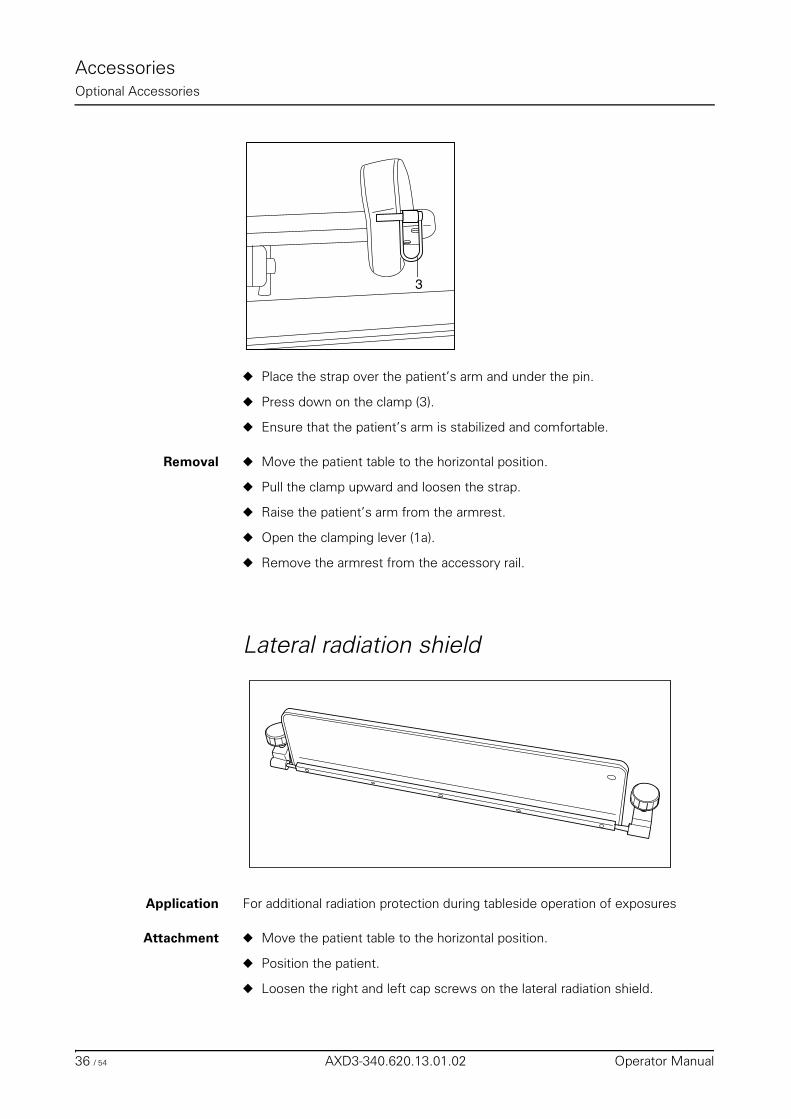
AccessoriesOptional Accessories
◆ Place the strap over the patient’s arm and under the pin.
◆ Press down on the clamp (3).
◆ Ensure that the patient’s arm is stabilized and comfortable.
Removal ◆ Move the patient table to the horizontal position.
◆ Pull the clamp upward and loosen the strap.
◆ Raise the patient’s arm from the armrest.
◆ Open the clamping lever (1a).
◆ Remove the armrest from the accessory rail.
Lateral radiation shield
Application For additional radiation protection during tableside operation of exposures
Attachment ◆ Move the patient table to the horizontal position.
◆ Position the patient.
◆ Loosen the right and left cap screws on the lateral radiation shield.
3
36 / 54 AXD3-340.620.13.01.02 Operator Manual
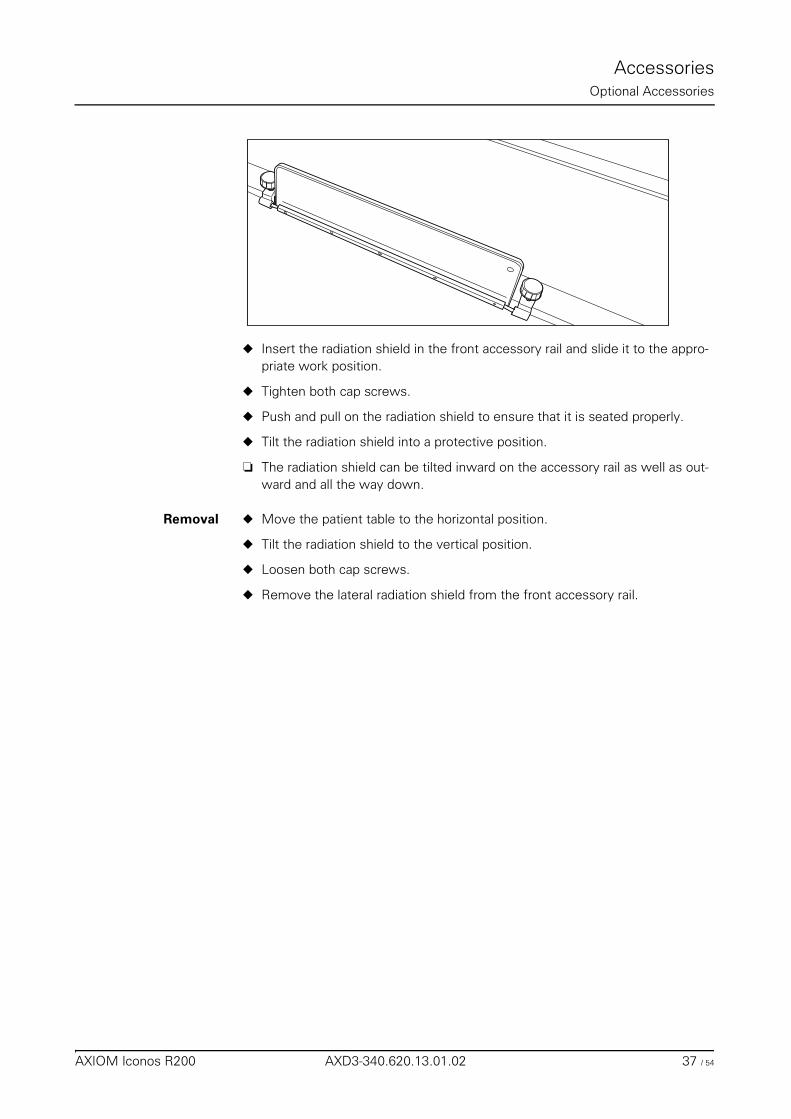
AccessoriesOptional Accessories
◆ Insert the radiation shield in the front accessory rail and slide it to the appro-priate work position.
◆ Tighten both cap screws.
◆ Push and pull on the radiation shield to ensure that it is seated properly.
◆ Tilt the radiation shield into a protective position.
❏ The radiation shield can be tilted inward on the accessory rail as well as out-ward and all the way down.
Removal ◆ Move the patient table to the horizontal position.
◆ Tilt the radiation shield to the vertical position.
◆ Loosen both cap screws.
◆ Remove the lateral radiation shield from the front accessory rail.
AXIOM Iconos R200 AXD3-340.620.13.01.02 37 / 54
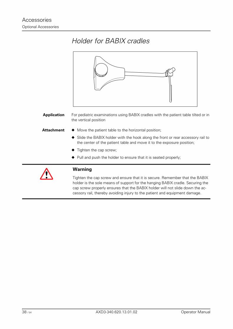
AccessoriesOptional Accessories
Holder for BABIX cradles
Application For pediatric examinations using BABIX cradles with the patient table tilted or in the vertical position
Attachment ◆ Move the patient table to the horizontal position;
◆ Slide the BABIX holder with the hook along the front or rear accessory rail to the center of the patient table and move it to the exposure position;
◆ Tighten the cap screw;
◆ Pull and push the holder to ensure that it is seated properly;
Warning
Tighten the cap screw and ensure that it is secure. Remember that the BABIX holder is the sole means of support for the hanging BABIX cradle. Securing the cap screw properly ensures that the BABIX holder will not slide down the ac-cessory rail, thereby avoiding injury to the patient and equipment damage.
38 / 54 AXD3-340.620.13.01.02 Operator Manual
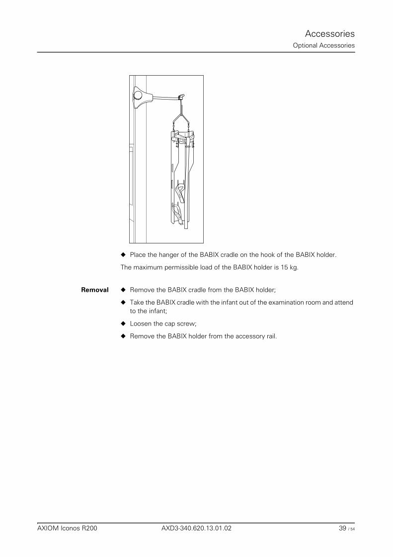
AccessoriesOptional Accessories
◆ Place the hanger of the BABIX cradle on the hook of the BABIX holder.
The maximum permissible load of the BABIX holder is 15 kg.
Removal ◆ Remove the BABIX cradle from the BABIX holder;
◆ Take the BABIX cradle with the infant out of the examination room and attend to the infant;
◆ Loosen the cap screw;
◆ Remove the BABIX holder from the accessory rail.
AXIOM Iconos R200 AXD3-340.620.13.01.02 39 / 54
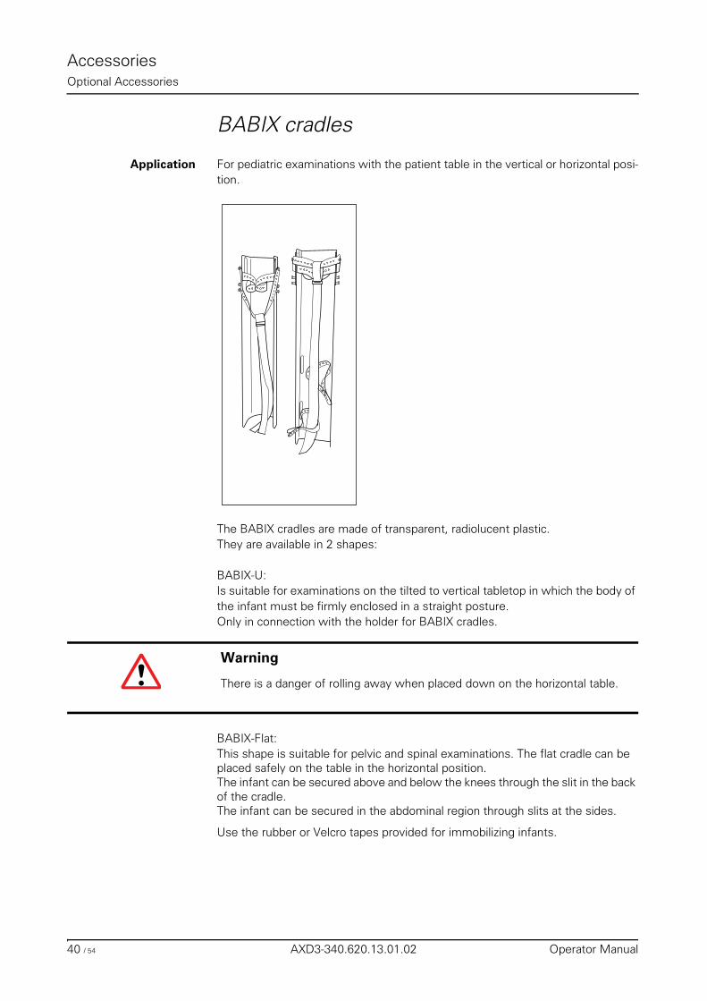
AccessoriesOptional Accessories
BABIX cradles
Application For pediatric examinations with the patient table in the vertical or horizontal posi-tion.
The BABIX cradles are made of transparent, radiolucent plastic.They are available in 2 shapes:
BABIX-U: Is suitable for examinations on the tilted to vertical tabletop in which the body of the infant must be firmly enclosed in a straight posture. Only in connection with the holder for BABIX cradles.
BABIX-Flat:This shape is suitable for pelvic and spinal examinations. The flat cradle can be placed safely on the table in the horizontal position.The infant can be secured above and below the knees through the slit in the back of the cradle.The infant can be secured in the abdominal region through slits at the sides.
Use the rubber or Velcro tapes provided for immobilizing infants.
Warning
There is a danger of rolling away when placed down on the horizontal table.
40 / 54 AXD3-340.620.13.01.02 Operator Manual
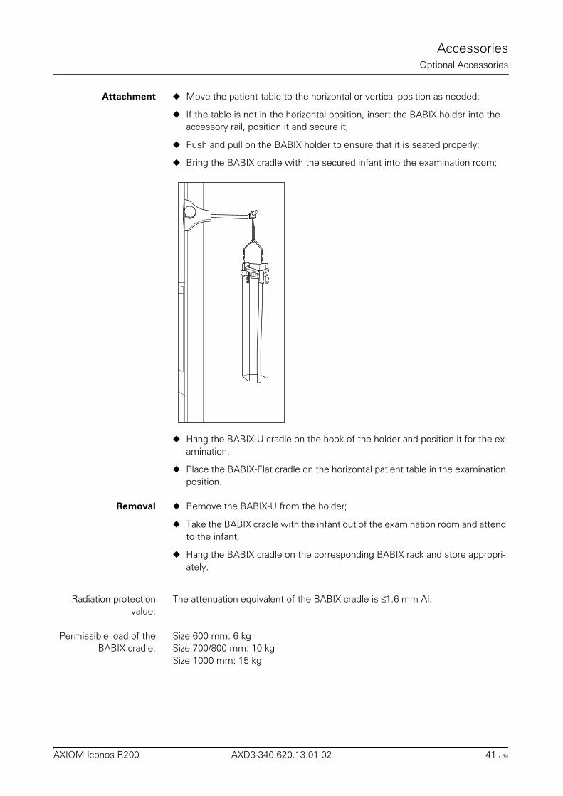
AccessoriesOptional Accessories
Attachment ◆ Move the patient table to the horizontal or vertical position as needed;
◆ If the table is not in the horizontal position, insert the BABIX holder into the accessory rail, position it and secure it;
◆ Push and pull on the BABIX holder to ensure that it is seated properly;
◆ Bring the BABIX cradle with the secured infant into the examination room;
◆ Hang the BABIX-U cradle on the hook of the holder and position it for the ex-amination.
◆ Place the BABIX-Flat cradle on the horizontal patient table in the examination position.
Removal ◆ Remove the BABIX-U from the holder;
◆ Take the BABIX cradle with the infant out of the examination room and attend to the infant;
◆ Hang the BABIX cradle on the corresponding BABIX rack and store appropri-ately.
Radiation protectionvalue:
The attenuation equivalent of the BABIX cradle is ≤ 1.6 mm Al.
Permissible load of theBABIX cradle:
Size 600 mm: 6 kgSize 700/800 mm: 10 kgSize 1000 mm: 15 kg
AXIOM Iconos R200 AXD3-340.620.13.01.02 41 / 54
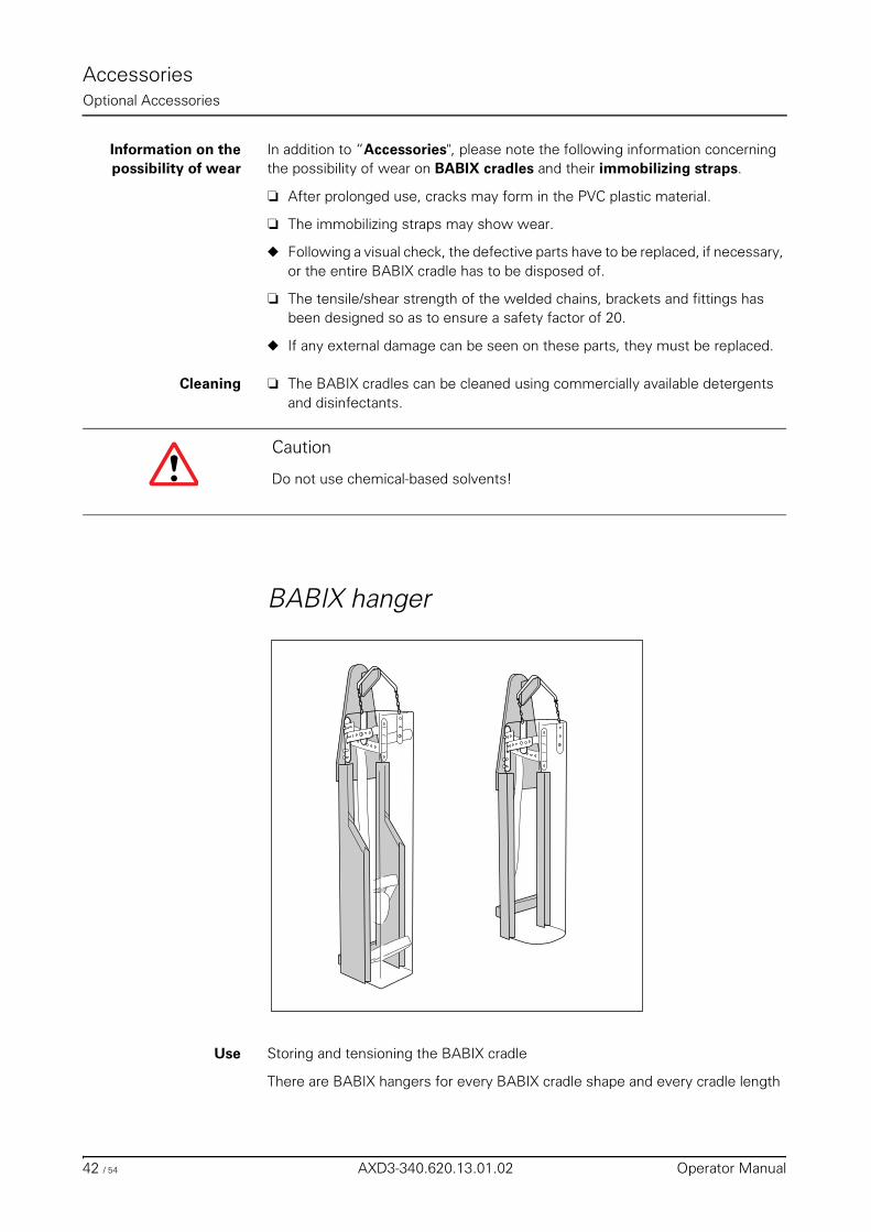
AccessoriesOptional Accessories
Information on the possibility of wear
In addition to “Accessories", please note the following information concerning the possibility of wear on BABIX cradles and their immobilizing straps.
❏ After prolonged use, cracks may form in the PVC plastic material.
❏ The immobilizing straps may show wear.
◆ Following a visual check, the defective parts have to be replaced, if necessary, or the entire BABIX cradle has to be disposed of.
❏ The tensile/shear strength of the welded chains, brackets and fittings has been designed so as to ensure a safety factor of 20.
◆ If any external damage can be seen on these parts, they must be replaced.
Cleaning ❏ The BABIX cradles can be cleaned using commercially available detergents and disinfectants.
BABIX hanger
Use Storing and tensioning the BABIX cradle
There are BABIX hangers for every BABIX cradle shape and every cradle length
Caution
Do not use chemical-based solvents!
42 / 54 AXD3-340.620.13.01.02 Operator Manual
AccessoriesOptional Accessories
Mounting theBABIX hanger
◆ Have the wooden holder fastened to the wall with the enclosed wall plugs and screws at a suitable place in working height.
Removing theBABIX cradles
◆ Pull the BABIX cradle carefully out from the slot of the BABIX hanger
◆ Hold the cradle tight
◆ Lift the cradle off from the wooden hook of the hanger
◆ Place the BABIX cradle on a secure base
◆ Position the infant carefully and comfortably in the BABIX cradle
◆ Immobilize the infant securely in the cradle
◆ Check for the safe position of the infant in the BABIX cradle
◆ Bring the infant into the already prepared X-ray room for the examination.
Keeping BABIX cra-dles
◆ Remove the infant from the cradle and attend to the infant
◆ Carry the cradle to the BABIX hanger of suitable shape and length
◆ Hook the cradle on the wooden hook with the opening towards the hanger
◆ Press the cradle at the two longitudinal sides into the slot of the hanger
◆ Check for firm seating of the BABIX cradle in the BABIX hanger.
Holder for pediatric cradle, manual➩ See separate Operator Manual
This holder is now also available for Iconos R200.
Patient positioning mattress
Application Mattress for attachment to the grip protection strip for comfortable patient posi-tioning.
Attachment ◆ Attach grip protection strip to head end.
◆ Place the mattress on the tabletop and pull loops over the cap screws of the grip protection strip.
Radiation protectionvalue:
The attenuation equivalent is < 0.5 mm Al.
AXIOM Iconos R200 AXD3-340.620.13.01.02 43 / 54
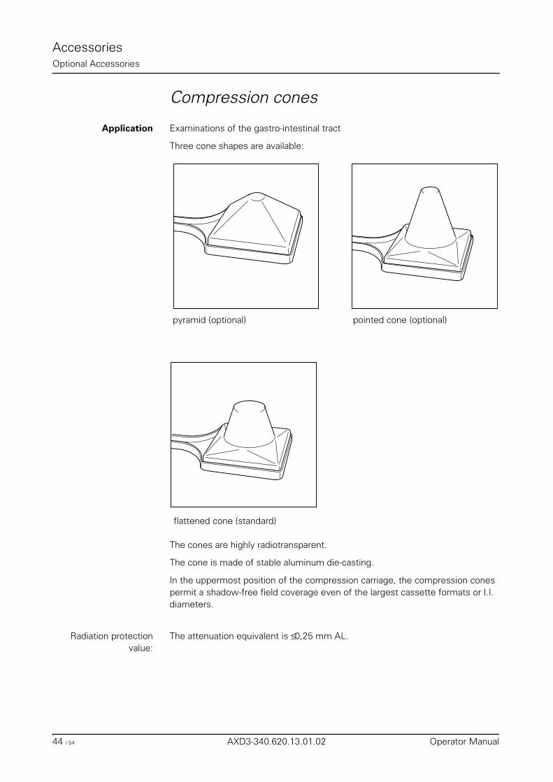
AccessoriesOptional Accessories
Compression cones
Application Examinations of the gastro-intestinal tract
Three cone shapes are available:
The cones are highly radiotransparent.
The cone is made of stable aluminum die-casting.
In the uppermost position of the compression carriage, the compression cones permit a shadow-free field coverage even of the largest cassette formats or I.I. diameters.
Radiation protectionvalue:
The attenuation equivalent is ≤ 0,25 mm AL.
pyramid (optional) pointed cone (optional)
flattened cone (standard)
44 / 54 AXD3-340.620.13.01.02 Operator Manual
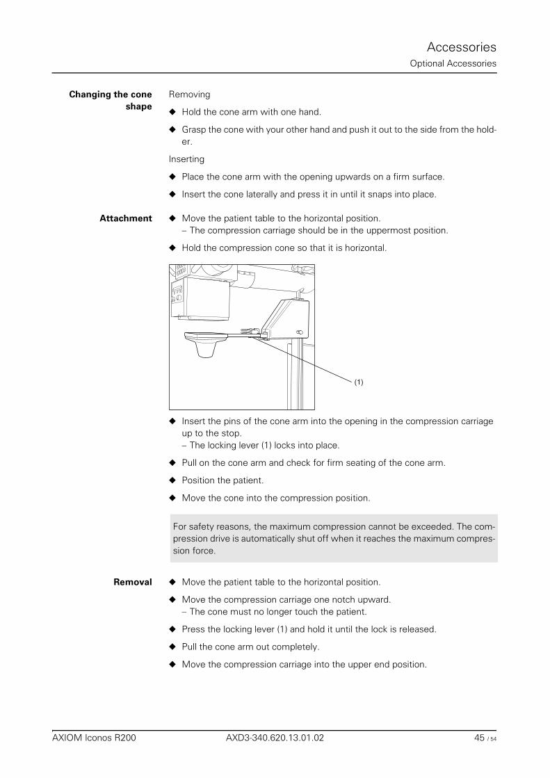
AccessoriesOptional Accessories
Changing the coneshape
Removing
◆ Hold the cone arm with one hand.
◆ Grasp the cone with your other hand and push it out to the side from the hold-er.
Inserting
◆ Place the cone arm with the opening upwards on a firm surface.
◆ Insert the cone laterally and press it in until it snaps into place.
Attachment ◆ Move the patient table to the horizontal position.– The compression carriage should be in the uppermost position.
◆ Hold the compression cone so that it is horizontal.
◆ Insert the pins of the cone arm into the opening in the compression carriage up to the stop.– The locking lever (1) locks into place.
◆ Pull on the cone arm and check for firm seating of the cone arm.
◆ Position the patient.
◆ Move the cone into the compression position.
Removal ◆ Move the patient table to the horizontal position.
◆ Move the compression carriage one notch upward.– The cone must no longer touch the patient.
◆ Press the locking lever (1) and hold it until the lock is released.
◆ Pull the cone arm out completely.
◆ Move the compression carriage into the upper end position.
(1)
For safety reasons, the maximum compression cannot be exceeded. The com-pression drive is automatically shut off when it reaches the maximum compres-sion force.
AXIOM Iconos R200 AXD3-340.620.13.01.02 45 / 54
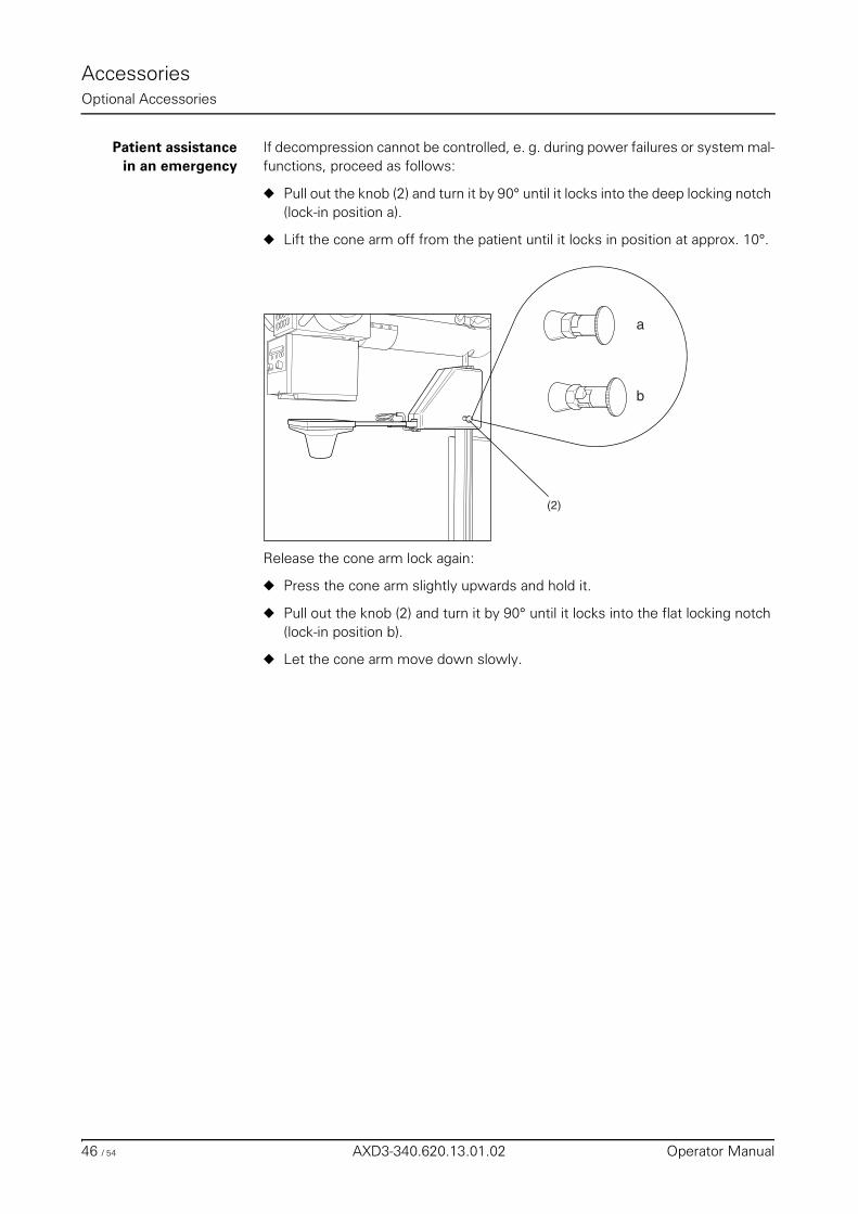
AccessoriesOptional Accessories
Patient assistancein an emergency
If decompression cannot be controlled, e. g. during power failures or system mal-functions, proceed as follows:
◆ Pull out the knob (2) and turn it by 90° until it locks into the deep locking notch (lock-in position a).
◆ Lift the cone arm off from the patient until it locks in position at approx. 10°.
Release the cone arm lock again:
◆ Press the cone arm slightly upwards and hold it.
◆ Pull out the knob (2) and turn it by 90° until it locks into the flat locking notch (lock-in position b).
◆ Let the cone arm move down slowly.
a
b
(2)
46 / 54 AXD3-340.620.13.01.02 Operator Manual
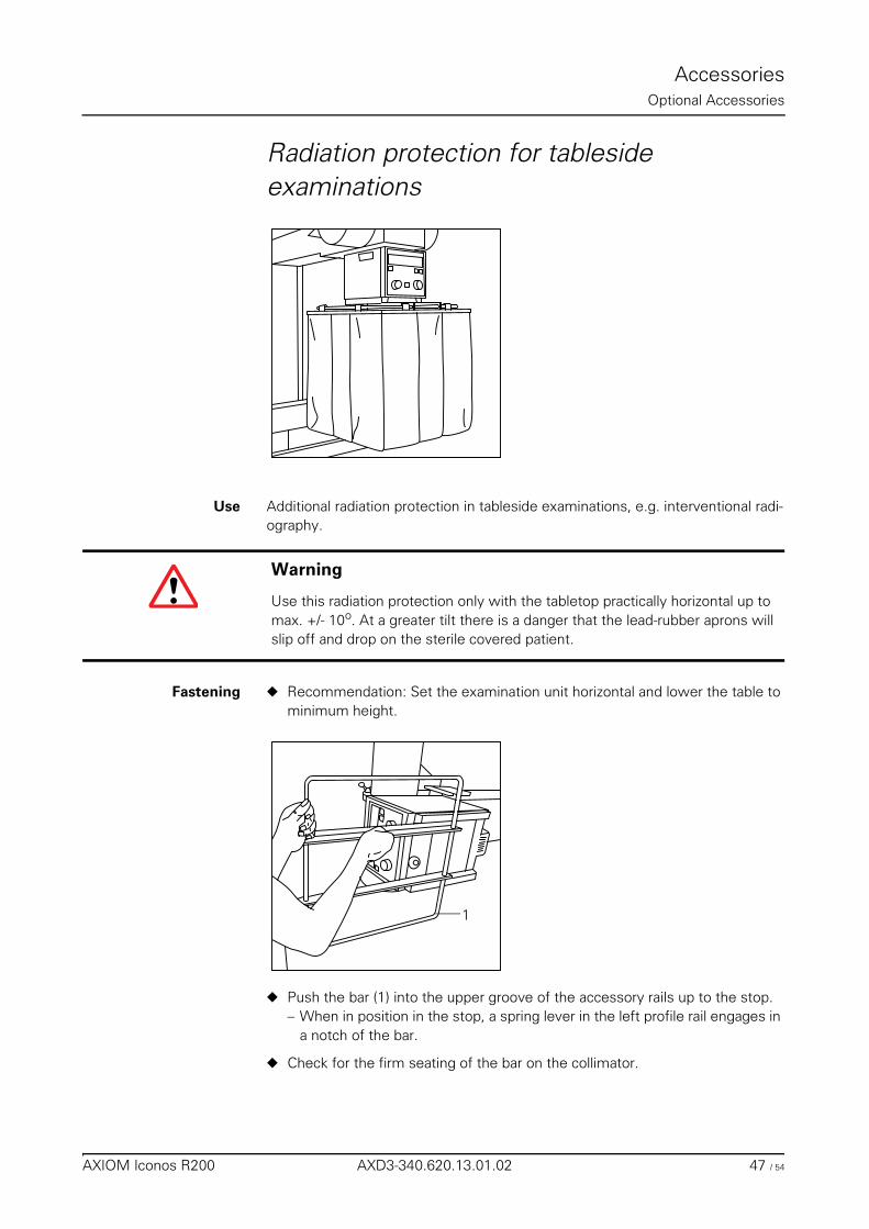
AccessoriesOptional Accessories
Radiation protection for tableside examinations
Use Additional radiation protection in tableside examinations, e.g. interventional radi-ography.
Fastening ◆ Recommendation: Set the examination unit horizontal and lower the table to minimum height.
◆ Push the bar (1) into the upper groove of the accessory rails up to the stop.– When in position in the stop, a spring lever in the left profile rail engages in
a notch of the bar.
◆ Check for the firm seating of the bar on the collimator.
Warning
Use this radiation protection only with the tabletop practically horizontal up to max. +/- 10o. At a greater tilt there is a danger that the lead-rubber aprons will slip off and drop on the sterile covered patient.
1
AXIOM Iconos R200 AXD3-340.620.13.01.02 47 / 54
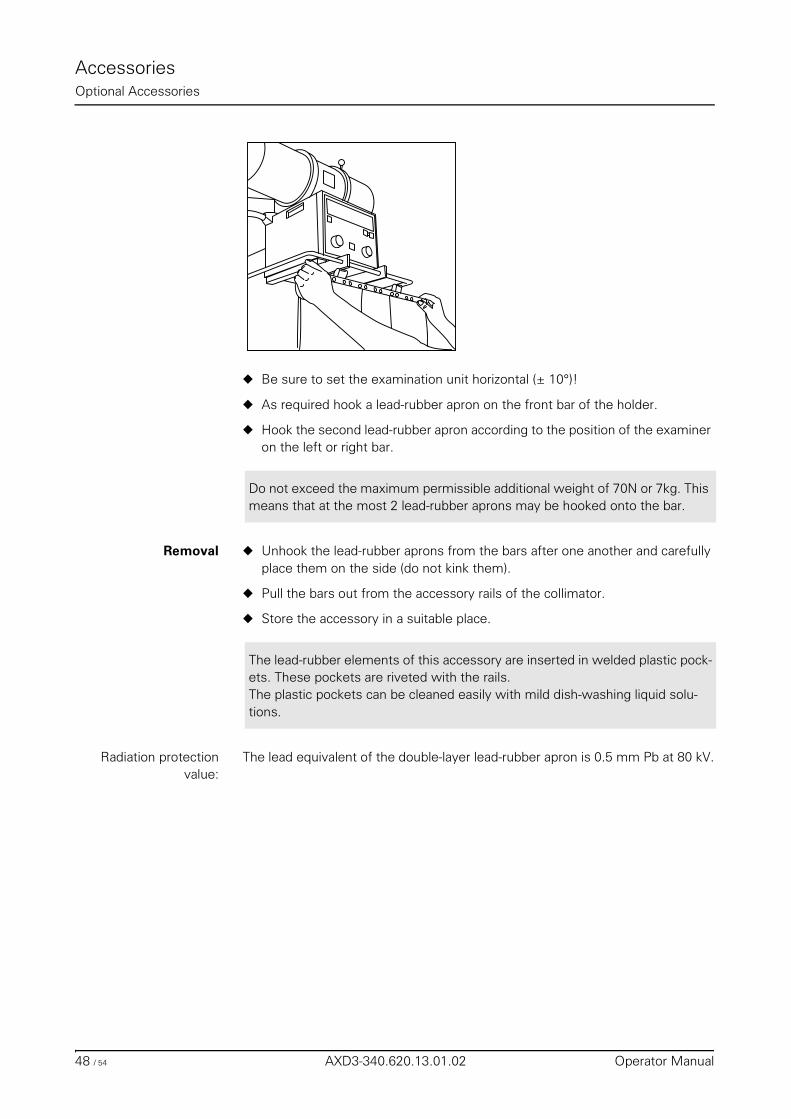
AccessoriesOptional Accessories
◆ Be sure to set the examination unit horizontal (± 10°)!
◆ As required hook a lead-rubber apron on the front bar of the holder.
◆ Hook the second lead-rubber apron according to the position of the examiner on the left or right bar.
Removal ◆ Unhook the lead-rubber aprons from the bars after one another and carefully place them on the side (do not kink them).
◆ Pull the bars out from the accessory rails of the collimator.
◆ Store the accessory in a suitable place.
Radiation protectionvalue:
The lead equivalent of the double-layer lead-rubber apron is 0.5 mm Pb at 80 kV.
Do not exceed the maximum permissible additional weight of 70N or 7kg. This means that at the most 2 lead-rubber aprons may be hooked onto the bar.
The lead-rubber elements of this accessory are inserted in welded plastic pock-ets. These pockets are riveted with the rails.The plastic pockets can be cleaned easily with mild dish-washing liquid solu-tions.
48 / 54 AXD3-340.620.13.01.02 Operator Manual
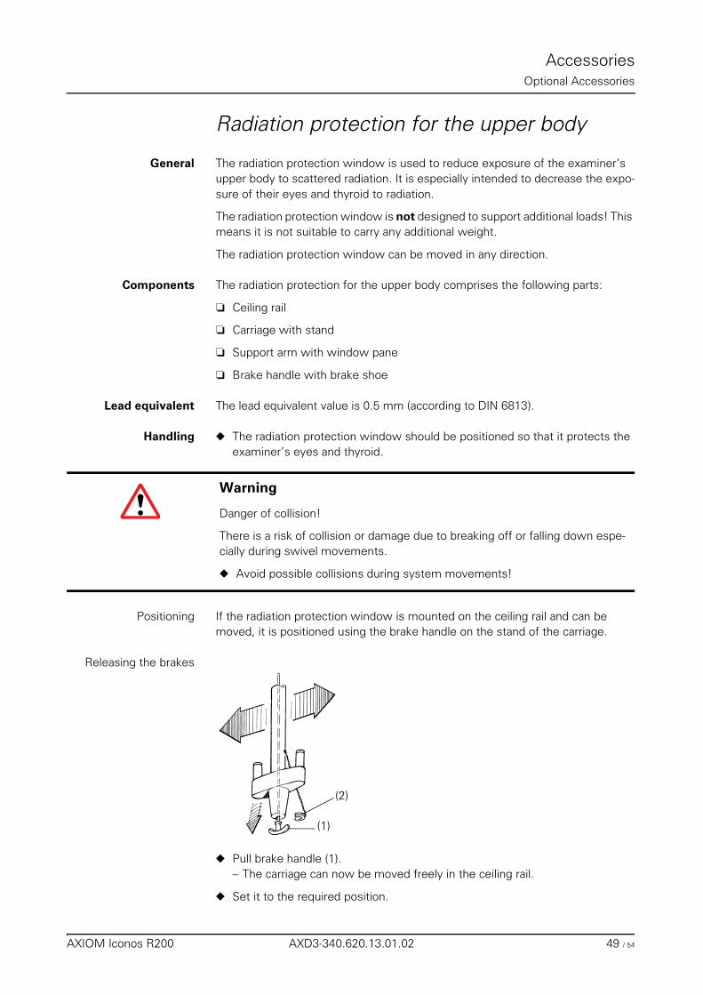
AccessoriesOptional Accessories
Radiation protection for the upper body
General The radiation protection window is used to reduce exposure of the examiner’s upper body to scattered radiation. It is especially intended to decrease the expo-sure of their eyes and thyroid to radiation.
The radiation protection window is not designed to support additional loads! This means it is not suitable to carry any additional weight.
The radiation protection window can be moved in any direction.
Components The radiation protection for the upper body comprises the following parts:
❏ Ceiling rail
❏ Carriage with stand
❏ Support arm with window pane
❏ Brake handle with brake shoe
Lead equivalent The lead equivalent value is 0.5 mm (according to DIN 6813).
Handling ◆ The radiation protection window should be positioned so that it protects the examiner’s eyes and thyroid.
Positioning If the radiation protection window is mounted on the ceiling rail and can be moved, it is positioned using the brake handle on the stand of the carriage.
Releasing the brakes
◆ Pull brake handle (1).– The carriage can now be moved freely in the ceiling rail.
◆ Set it to the required position.
Warning
Danger of collision!
There is a risk of collision or damage due to breaking off or falling down espe-cially during swivel movements.
◆ Avoid possible collisions during system movements!
(2)
(1)
AXIOM Iconos R200 AXD3-340.620.13.01.02 49 / 54
AccessoriesOptional Accessories
Engaging the brakes ◆ Release the brake handle.
Releasing the brakespermanently
◆ Pull the brake handle.
◆ Insert the brake shoe (2) so that the brake handle remains in the “pulled position”.– You can now move the carriage freely in the ceiling rail.
Engaging the brakes ◆ Pull the brake handle.
◆ Remove the brake shoe.
◆ Release the brake handle.
Cleaning anddisinfection
You can clean a slightly soiled lead glass pane with a lukewarm detergent solution and a soft cloth.
Heavy dirt and grime should be wiped off with a linen cloth moistened with alco-hol and then rinsed with clear water.
Bloodstains are best treated with cold water, contrast medium residue with warm water.
Use disinfectants commercially available for medical use to disinfect the radiation protection device. Then wipe it off with clear water.
Sterile cover Both window designs can be provided with sterile covers1; contact your Siemens sales representative.
While positioning the patient position the upper body radiation protection out-side of the system’s swivel range if you do not intend to use it.
1 optional
50 / 54 AXD3-340.620.13.01.02 Operator Manual
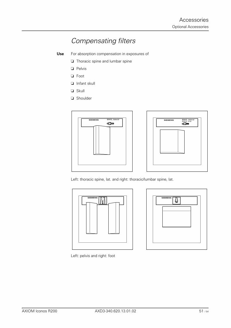
AccessoriesOptional Accessories
Compensating filters
Use For absorption compensation in exposures of
❏ Thoracic spine and lumbar spine
❏ Pelvis
❏ Foot
❏ Infant skull
❏ Skull
❏ Shoulder
Left: thoracic spine, lat. and right: thoracic/lumbar spine, lat.
Left: pelvis and right: foot
BWS, lateralSIEMENSBWS, a.p.BWS, lateralSIEMENS
SIEMENSSIEMENS
AXIOM Iconos R200 AXD3-340.620.13.01.02 51 / 54
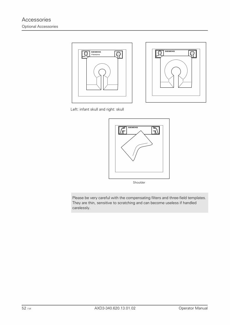
AccessoriesOptional Accessories
Left: infant skull and right: skull
Shoulder
SIEMENSSIEMENS
Pädiatrie
SIEMENS
Please be very careful with the compensating filters and three-field templates. They are thin, sensitive to scratching and can become useless if handled carelessly.
52 / 54 AXD3-340.620.13.01.02 Operator Manual
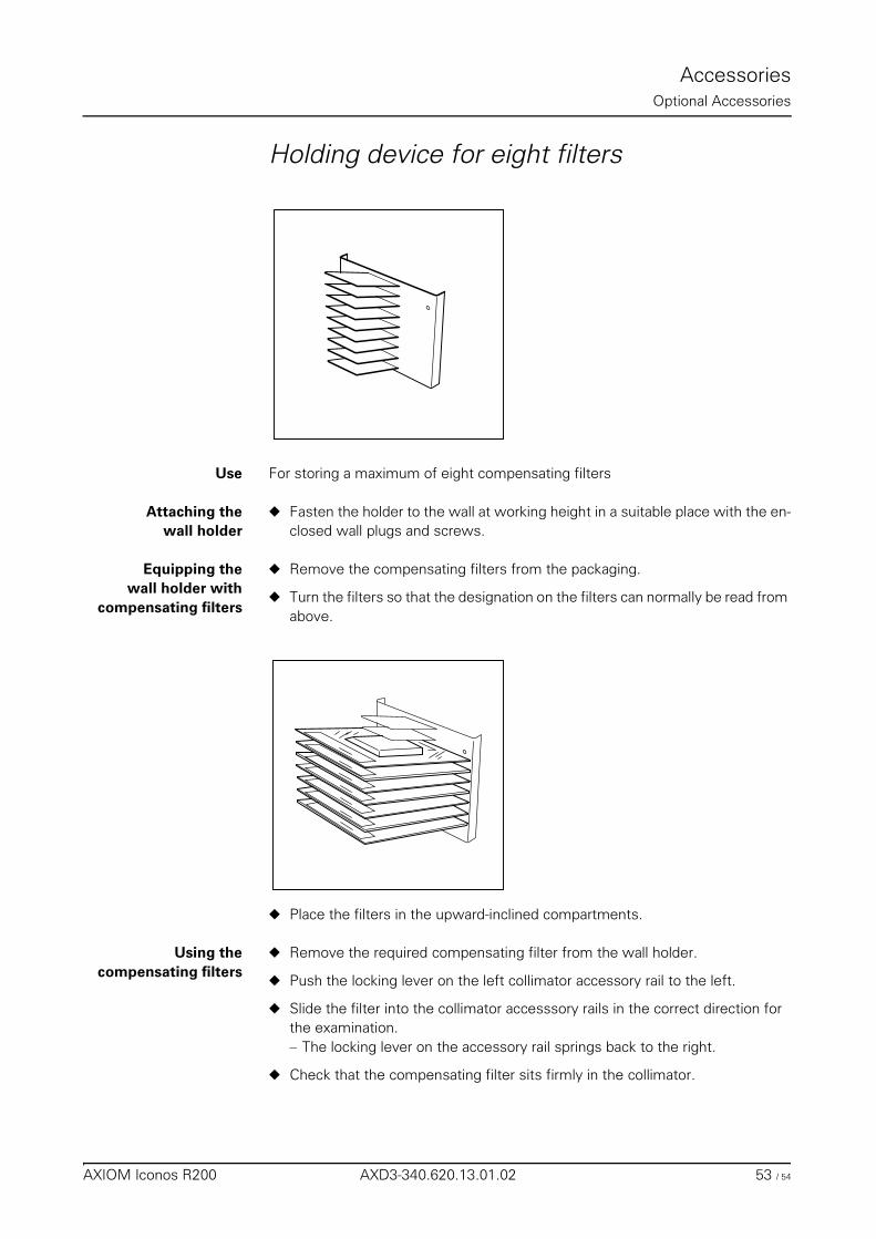
AccessoriesOptional Accessories
Holding device for eight filters
Use For storing a maximum of eight compensating filters
Attaching thewall holder
◆ Fasten the holder to the wall at working height in a suitable place with the en-closed wall plugs and screws.
Equipping thewall holder with
compensating filters
◆ Remove the compensating filters from the packaging.
◆ Turn the filters so that the designation on the filters can normally be read from above.
◆ Place the filters in the upward-inclined compartments.
Using thecompensating filters
◆ Remove the required compensating filter from the wall holder.
◆ Push the locking lever on the left collimator accessory rail to the left.
◆ Slide the filter into the collimator accesssory rails in the correct direction for the examination. – The locking lever on the accessory rail springs back to the right.
◆ Check that the compensating filter sits firmly in the collimator.
AXIOM Iconos R200 AXD3-340.620.13.01.02 53 / 54
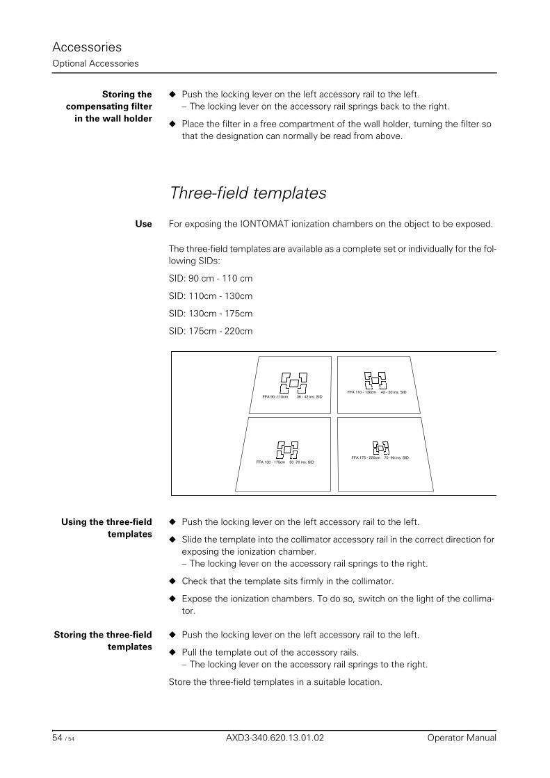
AccessoriesOptional Accessories
Storing thecompensating filter
in the wall holder
◆ Push the locking lever on the left accessory rail to the left. – The locking lever on the accessory rail springs back to the right.
◆ Place the filter in a free compartment of the wall holder, turning the filter so that the designation can normally be read from above.
Three-field templates
Use For exposing the IONTOMAT ionization chambers on the object to be exposed.
The three-field templates are available as a complete set or individually for the fol-lowing SIDs:
SID: 90 cm - 110 cm
SID: 110cm - 130cm
SID: 130cm - 175cm
SID: 175cm - 220cm
Using the three-fieldtemplates
◆ Push the locking lever on the left accessory rail to the left.
◆ Slide the template into the collimator accessory rail in the correct direction for exposing the ionization chamber. – The locking lever on the accessory rail springs to the right.
◆ Check that the template sits firmly in the collimator.
◆ Expose the ionization chambers. To do so, switch on the light of the collima-tor.
Storing the three-fieldtemplates
◆ Push the locking lever on the left accessory rail to the left.
◆ Pull the template out of the accessory rails.– The locking lever on the accessory rail springs to the right.
Store the three-field templates in a suitable location.
FFA 90 -110cm 36 - 42 ins. SIDFFA 110 - 130cm 42 - 50 ins. SID
FFA 130 - 175cm 50 -70 ins. SIDFFA 175 - 220cm 70 -90 ins. SID
54 / 54 AXD3-340.620.13.01.02 Operator Manual
Technical DescriptionTable of Contents
Operator Manual
Technical Description
Chapter: Identifying Labels
Position of the labels .......................................................................................................... 3Primary collimator ........................................................................................................... 4
Backside ............................................................................................................... 4Bottom ................................................................................................................. 4
Chapter: Technical Data
System ............................................................................................................................... 5
Unit ..................................................................................................................................... 6
Components ....................................................................................................................... 8
X-ray generator ................................................................................................................. 11
AXIOM Iconos R200 AXD3-340.620.13.01.02 1 / 12
Technical DescriptionTable of Contents
Operator Manual2 of 12 AXD3-340.620.13.01.02
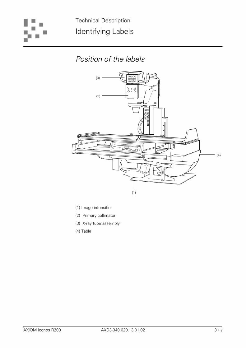
Technical Description
Identifying Labels
Position of the labels
(1) Image intensifier
(2) Primary collimator
(3) X-ray tube assembly
(4) Table
(1)
(2)
(3)
(4)
AX
IOM
AXIOM Iconos R200 AXD3-340.620.13.01.02 3 / 12
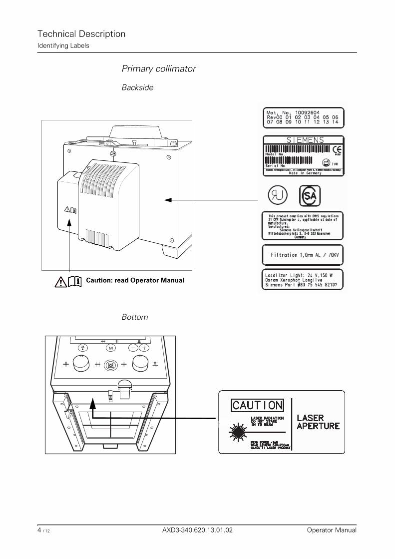
Technical DescriptionIdentifying Labels
Primary collimator
Backside
Bottom
Caution: read Operator Manual
M
4 / 12 AXD3-340.620.13.01.02 Operator Manual
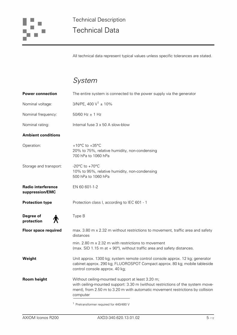
Technical Description
Technical Data
All technical data represent typical values unless specific tolerances are stated.
System
Power connection The entire system is connected to the power supply via the generator
Nominal voltage: 3/N/PE, 400 V1 ± 10%
Nominal frequency: 50/60 Hz ± 1 Hz
Nominal rating: Internal fuse 3 x 50 A slow-blow
Ambient conditions
Operation: +10°C to +35°C20% to 75%, relative humidity, non-condensing700 hPa to 1060 hPa
Storage and transport: -20°C to +70°C10% to 95%, relative humidity, non-condensing500 hPa to 1060 hPa
Radio interference suppression/EMC
EN 60 601-1-2
Protection type Protection class I, according to IEC 601 - 1
Degree of protection
Type B
Floor space required max. 3.80 m x 2.32 m without restrictions to movement, traffic area and safety distances
min. 2.80 m x 2.32 m with restrictions to movement(max. SID 1.15 m at + 90°), without traffic area and safety distances.
Weight Unit approx. 1300 kg; system remote control console approx. 12 kg; generator cabinet approx. 290 kg; FLUOROSPOT Compact approx. 80 kg; mobile tableside control console approx. 40 kg;
Room height Without ceiling-mounted support at least 3.20 m;with ceiling-mounted support: 3.30 m (without restrictions of the system move-ment), from 2.50 m to 3.20 m with automatic movement restrictions by collision computer
1 Pretransformer required for 440/480 V
AXIOM Iconos R200 AXD3-340.620.13.01.02 5 / 12
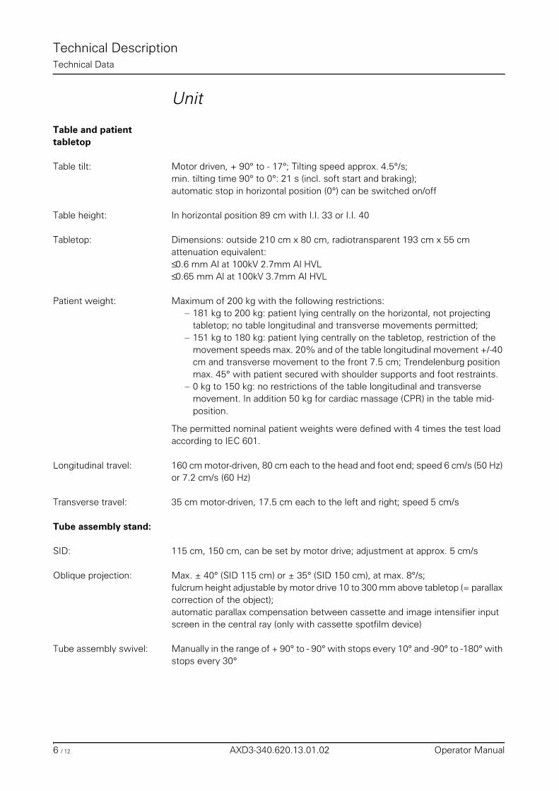
Technical DescriptionTechnical Data
Unit
Table and patient tabletop
Table tilt: Motor driven, + 90° to - 17°; Tilting speed approx. 4.5°/s;min. tilting time 90° to 0°: 21 s (incl. soft start and braking);automatic stop in horizontal position (0°) can be switched on/off
Table height: In horizontal position 89 cm with I.I. 33 or I.I. 40
Tabletop: Dimensions: outside 210 cm x 80 cm, radiotransparent 193 cm x 55 cmattenuation equivalent:≤ 0.6 mm Al at 100kV 2.7mm Al HVL≤ 0.65 mm Al at 100kV 3.7mm Al HVL
Patient weight: Maximum of 200 kg with the following restrictions:– 181 kg to 200 kg: patient lying centrally on the horizontal, not projecting
tabletop; no table longitudinal and transverse movements permitted;– 151 kg to 180 kg: patient lying centrally on the tabletop, restriction of the
movement speeds max. 20% and of the table longitudinal movement +/-40 cm and transverse movement to the front 7.5 cm; Trendelenburg position max. 45° with patient secured with shoulder supports and foot restraints.
– 0 kg to 150 kg: no restrictions of the table longitudinal and transverse movement. In addition 50 kg for cardiac massage (CPR) in the table mid-position.
The permitted nominal patient weights were defined with 4 times the test load according to IEC 601.
Longitudinal travel: 160 cm motor-driven, 80 cm each to the head and foot end; speed 6 cm/s (50 Hz) or 7.2 cm/s (60 Hz)
Transverse travel: 35 cm motor-driven, 17.5 cm each to the left and right; speed 5 cm/s
Tube assembly stand:
SID: 115 cm, 150 cm, can be set by motor drive; adjustment at approx. 5 cm/s
Oblique projection: Max. ± 40° (SID 115 cm) or ± 35° (SID 150 cm), at max. 8°/s;fulcrum height adjustable by motor drive 10 to 300 mm above tabletop (= parallax correction of the object);automatic parallax compensation between cassette and image intensifier input screen in the central ray (only with cassette spotfilm device)
Tube assembly swivel: Manually in the range of + 90° to - 90° with stops every 10° and -90° to -180° with stops every 30°
6 / 12 AXD3-340.620.13.01.02 Operator Manual
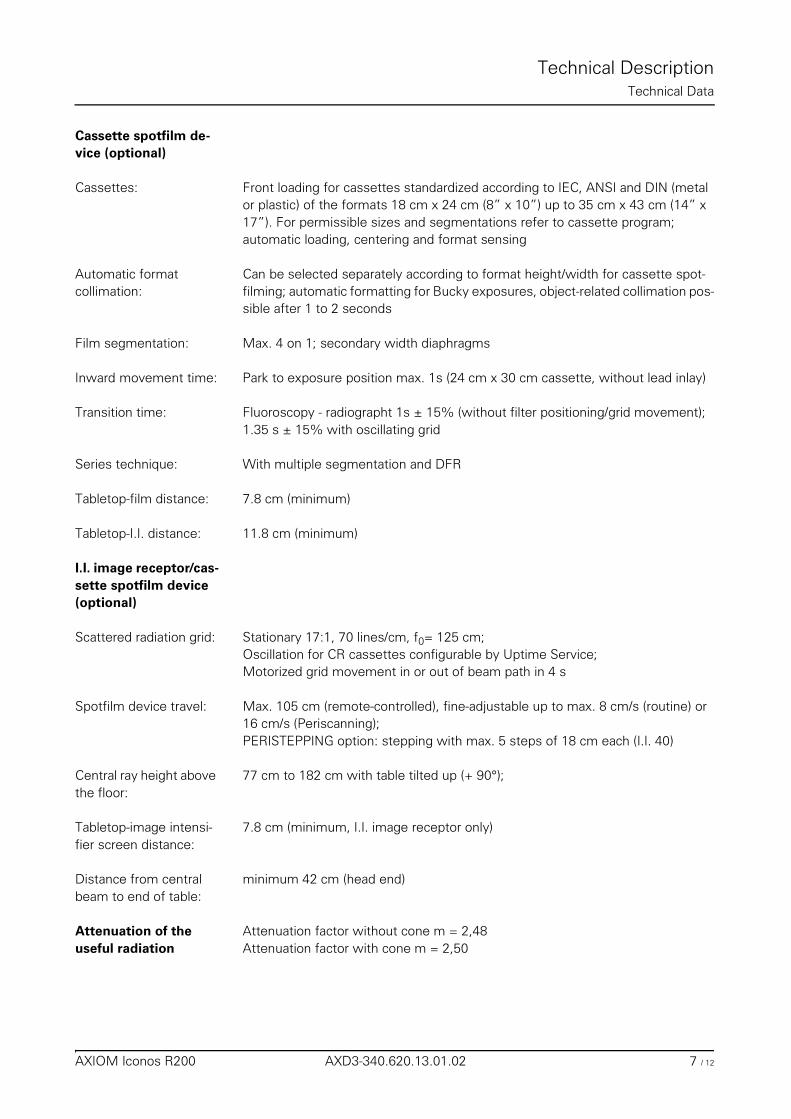
Technical DescriptionTechnical Data
Cassette spotfilm de-vice (optional)
Cassettes: Front loading for cassettes standardized according to IEC, ANSI and DIN (metal or plastic) of the formats 18 cm x 24 cm (8” x 10”) up to 35 cm x 43 cm (14” x 17”). For permissible sizes and segmentations refer to cassette program;automatic loading, centering and format sensing
Automatic format collimation:
Can be selected separately according to format height/width for cassette spot-filming; automatic formatting for Bucky exposures, object-related collimation pos-sible after 1 to 2 seconds
Film segmentation: Max. 4 on 1; secondary width diaphragms
Inward movement time: Park to exposure position max. 1s (24 cm x 30 cm cassette, without lead inlay)
Transition time: Fluoroscopy - radiographt 1s ± 15% (without filter positioning/grid movement); 1.35 s ± 15% with oscillating grid
Series technique: With multiple segmentation and DFR
Tabletop-film distance: 7.8 cm (minimum)
Tabletop-I.I. distance: 11.8 cm (minimum)
I.I. image receptor/cas-sette spotfilm device (optional)
Scattered radiation grid: Stationary 17:1, 70 lines/cm, f0= 125 cm;Oscillation for CR cassettes configurable by Uptime Service;Motorized grid movement in or out of beam path in 4 s
Spotfilm device travel: Max. 105 cm (remote-controlled), fine-adjustable up to max. 8 cm/s (routine) or 16 cm/s (Periscanning);PERISTEPPING option: stepping with max. 5 steps of 18 cm each (I.I. 40)
Central ray height above the floor:
77 cm to 182 cm with table tilted up (+ 90°);
Tabletop-image intensi-fier screen distance:
7.8 cm (minimum, I.I. image receptor only)
Distance from central beam to end of table:
minimum 42 cm (head end)
Attenuation of the useful radiation
Attenuation factor without cone m = 2,48Attenuation factor with cone m = 2,50
AXIOM Iconos R200 AXD3-340.620.13.01.02 7 / 12
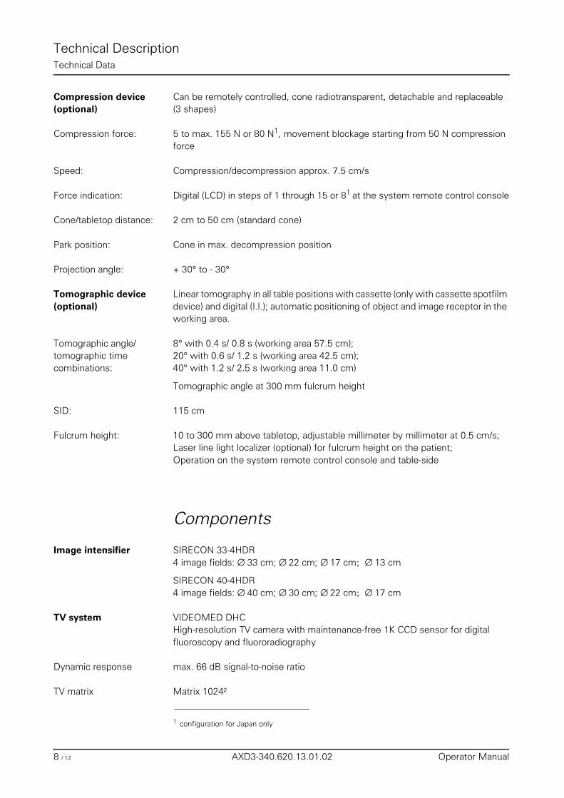
Technical DescriptionTechnical Data
Compression device (optional)
Can be remotely controlled, cone radiotransparent, detachable and replaceable (3 shapes)
Compression force: 5 to max. 155 N or 80 N1, movement blockage starting from 50 N compression force
Speed: Compression/decompression approx. 7.5 cm/s
Force indication: Digital (LCD) in steps of 1 through 15 or 81 at the system remote control console
Cone/tabletop distance: 2 cm to 50 cm (standard cone)
Park position: Cone in max. decompression position
Projection angle: + 30° to - 30°
Tomographic device (optional)
Linear tomography in all table positions with cassette (only with cassette spotfilm device) and digital (I.I.); automatic positioning of object and image receptor in the working area.
Tomographic angle/tomographic time combinations:
8° with 0.4 s/ 0.8 s (working area 57.5 cm);20° with 0.6 s/ 1.2 s (working area 42.5 cm);40° with 1.2 s/ 2.5 s (working area 11.0 cm)
Tomographic angle at 300 mm fulcrum height
SID: 115 cm
Fulcrum height: 10 to 300 mm above tabletop, adjustable millimeter by millimeter at 0.5 cm/s;Laser line light localizer (optional) for fulcrum height on the patient;Operation on the system remote control console and table-side
Components
Image intensifier SIRECON 33-4HDR4 image fields: ∅ 33 cm; ∅ 22 cm; ∅ 17 cm; ∅ 13 cm
SIRECON 40-4HDR4 image fields: ∅ 40 cm; ∅ 30 cm; ∅ 22 cm; ∅ 17 cm
TV system VIDEOMED DHCHigh-resolution TV camera with maintenance-free 1K CCD sensor for digital fluoroscopy and fluororadiography
Dynamic response max. 66 dB signal-to-noise ratio
TV matrix Matrix 1024²
1 configuration for Japan only
8 / 12 AXD3-340.620.13.01.02 Operator Manual
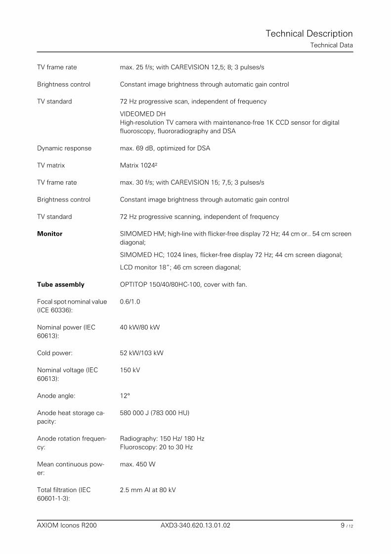
Technical DescriptionTechnical Data
TV frame rate max. 25 f/s; with CAREVISION 12,5; 8; 3 pulses/s
Brightness control Constant image brightness through automatic gain control
TV standard 72 Hz progressive scan, independent of frequency
VIDEOMED DH High-resolution TV camera with maintenance-free 1K CCD sensor for digital fluoroscopy, fluororadiography and DSA
Dynamic response max. 69 dB, optimized for DSA
TV matrix Matrix 1024²
TV frame rate max. 30 f/s; with CAREVISION 15; 7,5; 3 pulses/s
Brightness control Constant image brightness through automatic gain control
TV standard 72 Hz progressive scanning, independent of frequency
Monitor SIMOMED HM; high-line with flicker-free display 72 Hz; 44 cm or.. 54 cm screen diagonal;
SIMOMED HC; 1024 lines, flicker-free display 72 Hz; 44 cm screen diagonal;
LCD monitor 18”; 46 cm screen diagonal;
Tube assembly OPTITOP 150/40/80HC-100, cover with fan.
Focal spot nominal value (ICE 60336):
0.6/1.0
Nominal power (IEC 60613):
40 kW/80 kW
Cold power: 52 kW/103 kW
Nominal voltage (IEC 60613):
150 kV
Anode angle: 12°
Anode heat storage ca-pacity:
580 000 J (783 000 HU)
Anode rotation frequen-cy:
Radiography: 150 Hz/ 180 HzFluoroscopy: 20 to 30 Hz
Mean continuous pow-er:
max. 450 W
Total filtration (IEC 60601-1-3):
2.5 mm Al at 80 kV
AXIOM Iconos R200 AXD3-340.620.13.01.02 9 / 12
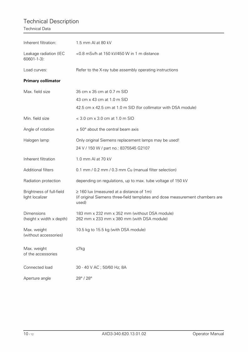
Technical DescriptionTechnical Data
Inherent filtration: 1.5 mm Al at 80 kV
Leakage radiation (IEC 60601-1-3):
<0.8 mSv/h at 150 kV/450 W in 1 m distance
Load curves: Refer to the X-ray tube assembly operating instructions
Primary collimator
Max. field size 35 cm x 35 cm at 0.7 m SID
43 cm x 43 cm at 1.0 m SID
42.5 cm x 42.5 cm at 1.0 m SID (for collimator with DSA module)
Min. field size < 3.0 cm x 3.0 cm at 1.0 m SID
Angle of rotation ± 50° about the central beam axis
Halogen lamp Only original Siemens replacement lamps may be used!
24 V / 150 W / part no.: 8375545 G2107
Inherent filtration 1.0 mm Al at 70 kV
Additional filters 0.1 mm / 0.2 mm / 0.3 mm Cu (manual filter selection)
Radiation protection depending on regulations, up to max. tube voltage of 150 kV
Brightness of full-field light localizer
≥ 160 lux (measured at a distance of 1m)(if original Siemens three-field templates and dose measurement chambers are used)
Dimensions(height x width x depth)
183 mm x 232 mm x 352 mm (without DSA module)262 mm x 233 mm x 380 mm (with DSA module)
Max. weight (without accessories)
10.5 kg to 15.5 kg (with DSA module)
Max. weight of the accessories
≤7kg
Connected load 30 - 40 V AC ; 50/60 Hz; 8A
Aperture angle 28° / 28°
10 / 12 AXD3-340.620.13.01.02 Operator Manual
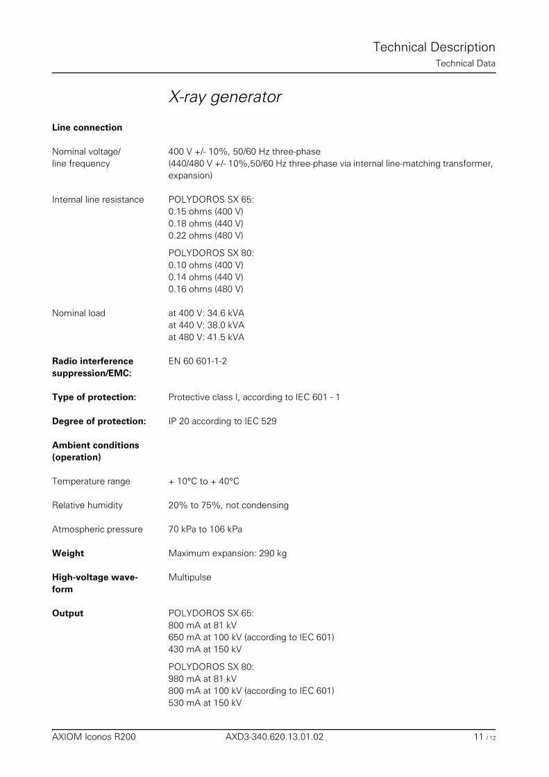
Technical DescriptionTechnical Data
X-ray generator
Line connection
Nominal voltage/line frequency
400 V +/- 10%, 50/60 Hz three-phase(440/480 V +/- 10%,50/60 Hz three-phase via internal line-matching transformer, expansion)
Internal line resistance POLYDOROS SX 65:0.15 ohms (400 V)0.18 ohms (440 V)0.22 ohms (480 V)
POLYDOROS SX 80:0.10 ohms (400 V)0.14 ohms (440 V)0.16 ohms (480 V)
Nominal load at 400 V: 34.6 kVAat 440 V: 38.0 kVAat 480 V: 41.5 kVA
Radio interferencesuppression/EMC:
EN 60 601-1-2
Type of protection: Protective class I, according to IEC 601 - 1
Degree of protection: IP 20 according to IEC 529
Ambient conditions(operation)
Temperature range + 10°C to + 40°C
Relative humidity 20% to 75%, not condensing
Atmospheric pressure 70 kPa to 106 kPa
Weight Maximum expansion: 290 kg
High-voltage wave-form
Multipulse
Output POLYDOROS SX 65:800 mA at 81 kV650 mA at 100 kV (according to IEC 601)430 mA at 150 kV
POLYDOROS SX 80:980 mA at 81 kV800 mA at 100 kV (according to IEC 601)530 mA at 150 kV
AXIOM Iconos R200 AXD3-340.620.13.01.02 11 / 12
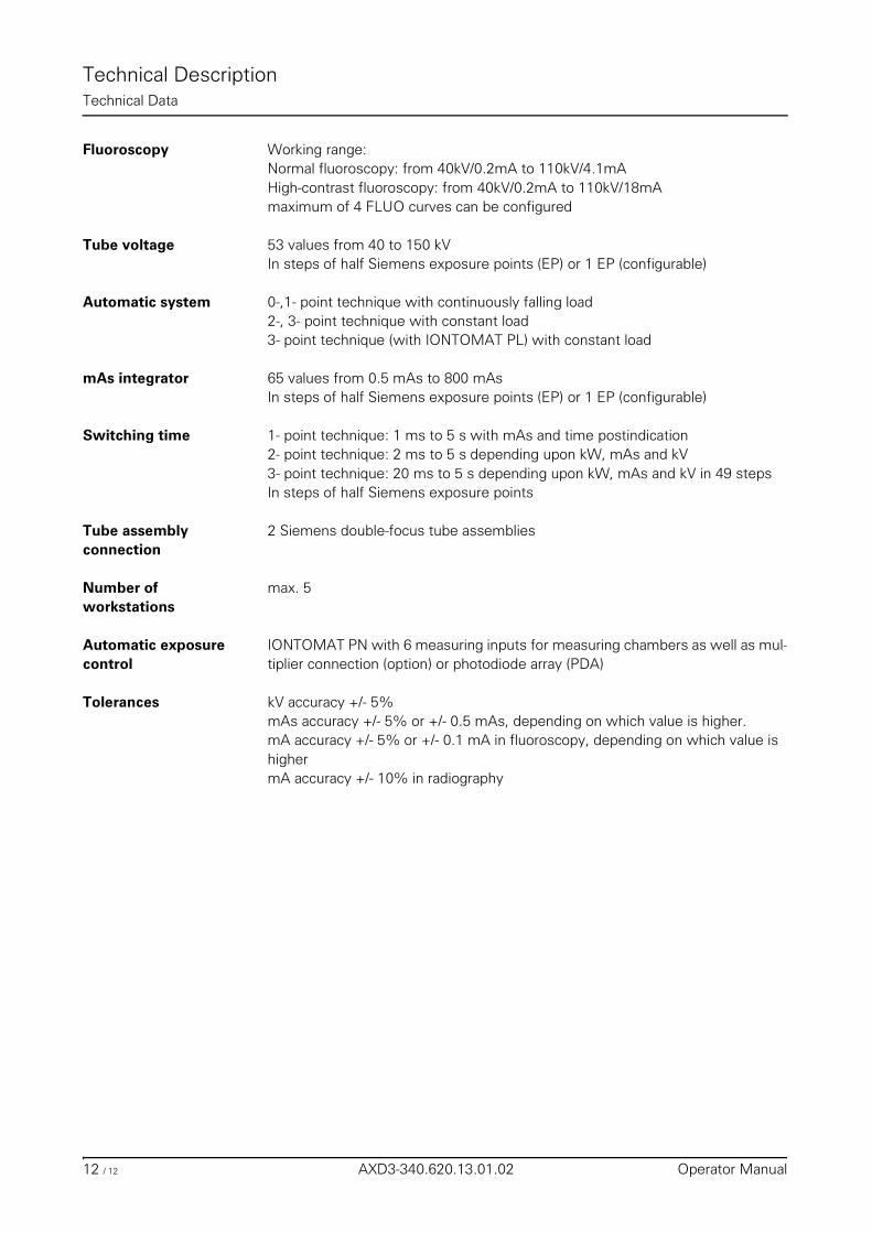
Technical DescriptionTechnical Data
Fluoroscopy Working range:Normal fluoroscopy: from 40kV/0.2mA to 110kV/4.1mAHigh-contrast fluoroscopy: from 40kV/0.2mA to 110kV/18mAmaximum of 4 FLUO curves can be configured
Tube voltage 53 values from 40 to 150 kV In steps of half Siemens exposure points (EP) or 1 EP (configurable)
Automatic system 0-,1- point technique with continuously falling load2-, 3- point technique with constant load3- point technique (with IONTOMAT PL) with constant load
mAs integrator 65 values from 0.5 mAs to 800 mAs In steps of half Siemens exposure points (EP) or 1 EP (configurable)
Switching time 1- point technique: 1 ms to 5 s with mAs and time postindication2- point technique: 2 ms to 5 s depending upon kW, mAs and kV3- point technique: 20 ms to 5 s depending upon kW, mAs and kV in 49 stepsIn steps of half Siemens exposure points
Tube assemblyconnection
2 Siemens double-focus tube assemblies
Number of workstations
max. 5
Automatic exposurecontrol
IONTOMAT PN with 6 measuring inputs for measuring chambers as well as mul-tiplier connection (option) or photodiode array (PDA)
Tolerances kV accuracy +/- 5%mAs accuracy +/- 5% or +/- 0.5 mAs, depending on which value is higher.mA accuracy +/- 5% or +/- 0.1 mA in fluoroscopy, depending on which value is highermA accuracy +/- 10% in radiography
12 / 12 AXD3-340.620.13.01.02 Operator Manual