Embed Size (px)
Citation preview

7/17/2019 MA_LMI-100_110_1050_1150_20120613_web.pdf
http://slidepdf.com/reader/full/malmi-1001101050115020120613webpdf 1/24
AMO GmbH
AMOSIN ®
Induktives LängenmesssystemInductive Length Measuring System
MontageanleitungInstallation and
Mounting Instructions
LMI-100/110LMI-1050/1150SN: MA_LMI-1xxx_20120620

7/17/2019 MA_LMI-100_110_1050_1150_20120613_web.pdf
http://slidepdf.com/reader/full/malmi-1001101050115020120613webpdf 2/24

7/17/2019 MA_LMI-100_110_1050_1150_20120613_web.pdf
http://slidepdf.com/reader/full/malmi-1001101050115020120613webpdf 3/24
3
Übereinstimmung mit EMV-Richtlinien:
Das Längenmesssystem stimmt mit den entsprechenden Normenund Richtlinien der elektromagnetischen Verträglichkeit überein. Dieswurde gemäß folgender Normen geprüft:
EN 61000-4-4 (1995): Prüfung der Störfestigkeit gegen schnelletransiente elektrische Störgrößen / Burst EMV - Schärfegrad 4EN 61000-4-2 (1995): Störfestigkeit gegen die Entladung statische Elektrizität / ESD - EMV-Schärfegrad 4EN 55011: Grenzwerte und Messverfahren für Funkstörungen von industriellen, wissenschaftli-chen und medizinischen Hochfrequenzgeräten (ISM-Geräten) -Störaussendung
Sicherheit:
Die in diesem Handbuch empfohlenen Maßnahmen für die Installation und den Montagevorgangdes Messsystems sind unbedingt zu beachten. Bei Missachtung können unsichere Bedienungbzw. Schäden auftreten. In diesen Fällen erlischt der Anspruch auf Gewährleistung!
Sorgfalt:
Das Längenmesssystem und die dazugehörigen Produkte sind hochwertige Präzisionsbauteileund müssen daher mit dementsprechender Sorgfalt behandelt werden.
Gewährleistung:
AMO Automatisierung Messtechnik Optik GmbH gewährt auf die Komponenten des Längen-messsystems eine Gewährleistungszeit von 24 Monaten ab Lieferdatum. Bei falscher Bedie-nung oder Montage, unzureichender oder falscher elektrischer Anschlüsse, Betrieb außerhalbder spezizierten Grenzen, Eingriffe in die Elektronik oder Mechanik durch nicht autorisiertes
Personal oder Änderung der Komponenten erlischt der Anspruch.
Produktänderung:
AMO Automatisierung Messtechnik Optik GmbH behält sich vor, jederzeit die technischen Datender in diesem Handbuch beschriebenen Komponenten zu verändern und zu verbessern.
Conformity to EMC guidelines:
The length measuring system complies with corresponding standards and electromagneticcompatibility guidelines. Compliance is substantiated by the followingstandards:
EN 61000-4-4 (1995): Inspection of interference immunity to fast, transient, electricalinterference variables / Burst EMC - Severity 4EN 61000-4-2 (1995): Interference immunity to electrostatic discharge / ESD - ECM -Severity 4EN 55011: Limits and measuring methods for radio interference from industrial, scientic and
medical high-frequency devices and equipment (ISM devices)
Safety:
The measures recommended in this manual for the installation and mounting of the measuringsystem must be complied with. Disregard of this information may give rise to unsafe operatingsituations and/or damage. Warranty claims shall not be accepted in such cases!
Care:
The length measuring system and its associated products are high-grade precision componentsand must therefore be handled with appropriate care.
Warranty:
AMO Automatisierung Messtechnik Optik GmbH shall grant a warranty period of 24 months fromthe date of delivery on the components of the length measuring systems. Incorrect operationor assembly/installation, unsatisfactory or incorrect electrical connection, operation outside thespecied limits, tampering with electronic or mechanical systems by unauthorized personnel or
modications to components shall invalidate all warranty claims.
Product changes:
AMO Automatisierung Messtechnik Optik GmbH reserves the right to make changes to improvethe technical data of the components described in this manual.
AllgemeinGeneral
RoHS Konform RoHS compliant
7/17/2019 MA_LMI-100_110_1050_1150_20120613_web.pdf
http://slidepdf.com/reader/full/malmi-1001101050115020120613webpdf 4/24
4
Lieferumfang LMI-100 / 1050 / 110 / 1150Items supplied LMI-100 / 1050 / 110 / 1150
Abtastkopf LMK-100/1050/110/1150, LMKF-1.110/1150Scanning head LMK-100/1050/110/1150,
LMKF-110/1150
Maßband LMB-100/1050/110/11502.Measuring scale LMB-100/1050/110/1150
Maßband mit Träger LMB-400/4050/410/41503.(alternativ zu LMB-100/1050/110/1150)Measuring scale on carrier LMB-400/410
(alternative to LMB-100/1050/110/1150)
Steckerelektronik (nur in Verbindung mit Abtast-4.kopf LMK-100/1050)Connector electronics (only in combination with
LMK-100/1050)
Abstandsfolie 0,15 mm (LMK-100/110),5.0,1 mm (LMK-1050/1150)Spacer lm 0.15 mm (LMK-100/110),
0,1 mm (LMK-1050/1150)2 Schrauben M4x10 für LMK-110/1150 oder6.M3x16 für LMK-100/10502 screws M4x10 for LMK-110/1150 or M3x16
for LMK-100/1050
Montageanleitung7.Mounting instructions
Prüfzertikat 8.Test certicate
Messprotokoll (Option)9.
Calibration chart (optional)Verlängerungskabel VK 4 (Option)10.Extension cable VK 4 (optional)
11. Endlagenmagnete (Option) End position magnets (optional) - Limit switch
1
2
3
4
11
44
7/17/2019 MA_LMI-100_110_1050_1150_20120613_web.pdf
http://slidepdf.com/reader/full/malmi-1001101050115020120613webpdf 5/24
LMI-100/1105
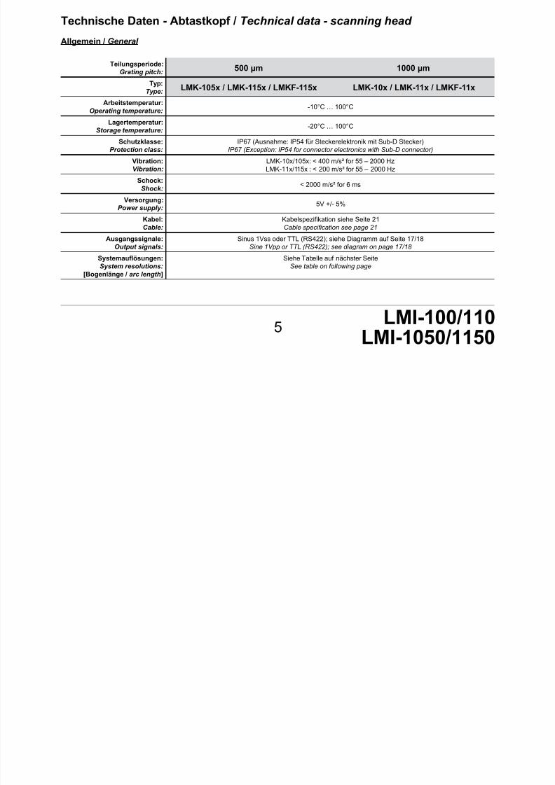
Teilungsperiode:Grating pitch:
500 µm 1000 µm
Typ:Type: LMK-105x / LMK-115x / LMKF-115x LMK-10x / LMK-11x / LMKF-11x
Arbeitstemperatur:Operating temperature:
-10°C … 100°C
Lagertemperatur:Storage temperature:
-20°C … 100°C
Schutzklasse:Protection class:
IP67 (Ausnahme: IP54 für Steckerelektronik mit Sub-D Stecker)IP67 (Exception: IP54 for connector electronics with Sub-D connector)
Vibration:Vibration:
LMK-10x/105x: < 400 m/s² for 55 – 2000 HzLMK-11x/115x : < 200 m/s² for 55 – 2000 Hz
Schock:Shock:
< 2000 m/s² for 6 ms
Versorgung:Power supply:
5V +/- 5%
Kabel:Cable:
Kabelspezikation siehe Seite 21
Cable specication see page 21
Ausgangssignale:Output signals:
Sinus 1Vss oder TTL (RS422); siehe Diagramm auf Seite 17/18Sine 1Vpp or TTL (RS422); see diagram on page 17/18
Systemauösungen:System resolutions:
[Bogenlänge / arc length]
Siehe Tabelle auf nächster SeiteSee table on following page
Technische Daten - Abtastkopf / Technical data - scanning head
Allgemein / General

7/17/2019 MA_LMI-100_110_1050_1150_20120613_web.pdf
http://slidepdf.com/reader/full/malmi-1001101050115020120613webpdf 6/24
6
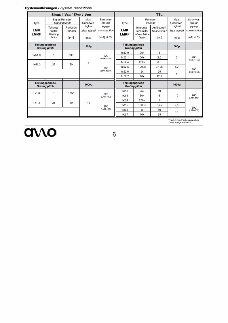
Systemauösungen / System resolutions
Sinus 1 Vss / Sine 1 Vpp TTL
Type
LMK
LMKF
Signal PeriodenSignal periods
Max.Geschwin-
digkeit
Max. speed
[m/s]
Stromver-brauch
Power
consumption
[mA] at 5V
Type
LMK
LMKF
PeriodenPeriods
Max.Geschwin-
digkeit
Max. speed
[m/s]
Stromver-brauch
Power
consumption
[mA] at 5V
Teilungs-faktor
Dividing
factor
PeriodenPeriods
[µm]
Interpola-tionsfaktor
Interpolation
factor
Auösung(1) Resolution(1)
[µm]
TeilungsperiodeGrating pitch
500µTeilungsperiode
Grating pitch500µ
1x51.0 1 500
5
220(LMK-1150)
260
(LMK-1050)
1x52.0 25x 5
5 260(LMK-1150)
300(LMK-1050)
1x52.1 50x 2,5
1x51.3 25 201x52.4 250x 0,5
1x52.5 1000x 0,125 1,2
1x52.6 5x 25 51x52.7 10x 12,5
TeilungsperiodeGrating pitch
1000µTeilungsperiode
Grating pitch1000µ
1x1.0 1 1000
10
220(LMK-110)
260(LMK-100)
1x2.0 25x 10
10 260(LMK-110)
300(LMK-100)
1x2.1 50x 5
1x1.3 25 401x2.4 250x 1
1x2.5 1000x 0,25 2,5
1x5.6 5x 5010
1x2.7 10x 25
(1) nach 4-fach Flankenauswertung(1) after 4-edge evaluation
7/17/2019 MA_LMI-100_110_1050_1150_20120613_web.pdf
http://slidepdf.com/reader/full/malmi-1001101050115020120613webpdf 7/24
LMI-100/1107
Abmessungen LMK-100 / 1050Dimensions LMK-100 / 1050
Maßband Typ LMB-100:
Measuring scale type LMB-100:
Maßband Typ LMB-400
Measuring scale type LMB-400:
1 0
=
=
Referenzmarke mittig im Abtastkopf Reference mark in the middle of t he
scanning head Referenzmarke MaßbandReference mark measuring scale
LMB-100 / LMB-1050
0,10,1
0,1/1000
5 , 2 16= = ~6
35,5
2x 3,5
0 , 8 ( L M B - 1 0 0 )
9 , 9 5 ( L M K - 1 0 0 )
0,10,1
0,03
12
1 2
0 , 1 5
0 , 1 ( L M K - 1 0 0 )
0 , 1
0 , 0 5 ( L M K - 1 0 5 0 )
1 ±0,5
0,10,1
L u f t s p a l t m i t F o l i e e i n g e s t e l l t
A i r g a p s e t w i t h
s p a c e r f i l m
+ ZählrichtungCount direction
0 , 6 ( L M B - 1 0 5 0 )
9 , 7 ( L M K - 1 0 5 0 )
16= =
35,5
~6
2 x 3 , 5
1 4 , 2 2 ( L M K - 1 0 5 0 )
1 4 , 2 7 ( L M K - 1 0 0 )
5 , 2
LMB-400 / LMB-4050
0,10,1
0,03
( 5 , 1
)
14
12
1 2
= (1 0,5) für LMK-100
0 , 1 ± 0 , 0
5
( L M K - 1 0 5 0 )
0 , 1 5 ± 0 , 1 ( L M K - 1 0 0 )
0 , 1 0 , 1
LMB-400 / LMB-4050
Referenzmarke MaßbandReference mark measuring scale
Referenzmarke mittig im Abtastkopf Reference mark in the middle of the
scanning head
0,10,1
0,1/1000ReferenzReference
ZählrichtungCount direction
L u f t s p a l t m
i t F o l i e e i n g e s t e l l t
A i r g a p s e
t w i t h s p a c e r f i l m
+
=(1 0,3) für LMK-1050
Für die Montage von LMB-4xx gibt es eine eigene MontageanleitungFor mounting the LMB-4xx there is a separate mounting assembly available
7/17/2019 MA_LMI-100_110_1050_1150_20120613_web.pdf
http://slidepdf.com/reader/full/malmi-1001101050115020120613webpdf 8/24
8
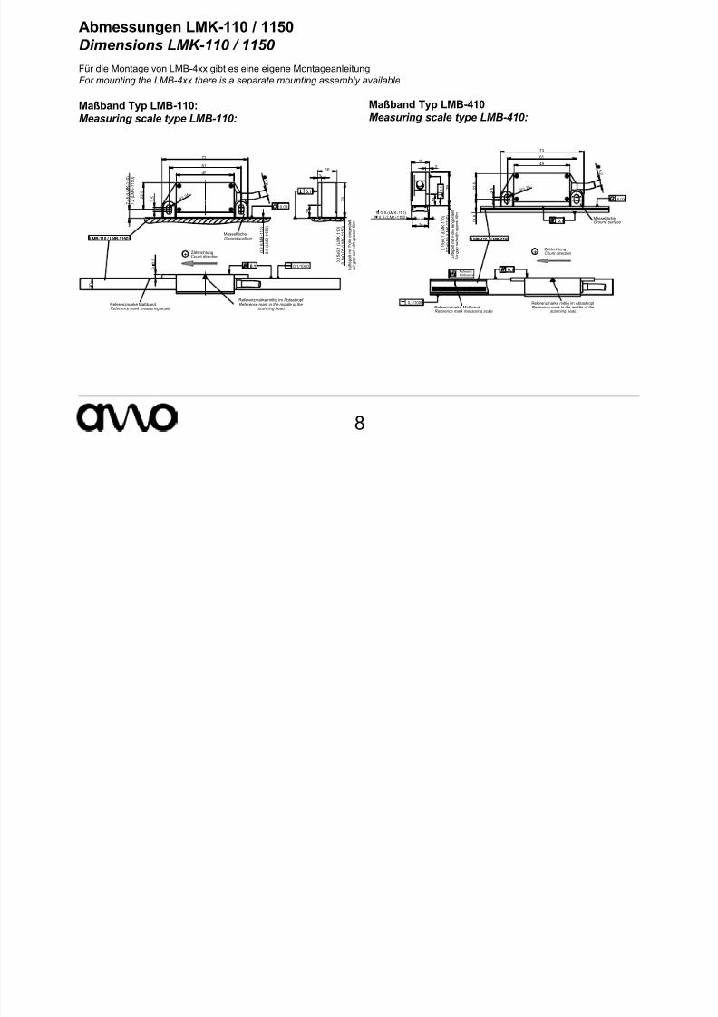
Abmessungen LMK-110 / 1150Dimensions LMK-110 / 1150
Maßband Typ LMB-110:Measuring scale type LMB-110:
Maßband Typ LMB-410Measuring scale type LMB-410:
49
61
73
R 2, 2 5
3 , 5
5 , 2
2 2 , 5
0 , 8
( L M B - 1 1 0 )
7 , 4
5 ( L M K - 1 1 0 )
MasseflächeGround surface LMB-110 / LMB-1150
0,03
1 0
2 9
3
16
0 , 1
± 0 , 0
5 ( L M K - 1 1 5 0 )
0 , 1
5 ± 0 , 1
( L M K - 1 1 0 )
0,10,1
3
0 , 5
1 0
Referenzmarke MaßbandReference mark measuring scale
LMB-110 / LMB-1150
Referenzmarke mittig im Abtastkopf Reference mark in the middle of the
scanning head
0,10,1 0,1/1000
+ ZählrichtungCount direction
L u f t s p a l t m i t F o l i e e i n g e s t e l l t
A i r g a p s e t w i t h s p a c e r f i l m
0 , 6
( L M B - 1 1 5 0 )
7 , 2
( L M K - 1 1 5 0 )
49
61
73
R 2, 2 5
3 , 5
5 , 2
1 1
, 8
2 2
, 5
MasseflächeGround surface
LMB-410 / LMB-4150
0,10,1
0,03
LMB-410 / LMB-4150
Referenzmarke MaßbandReference mark measuring scale
Referenzmarke mittig im Abtastkopf Reference mark in the middle of the
scanning head
0,10,1
0,1/1000
3
16
2 9
1 0
0 , 1
± 0
, 0 5 ( L M K - 1 1 5 0 )
0 , 1
5 ± 0
, 1 ( L M K
- 1 1 0 )
14
1 0,3 (LMK-1150)1 0,5 (LMK-110)
==
0 , 1
ReferenzReference
+ZählrichtungCount direction
L u
f t s p a
l t m
i t F o
l i e e
i n g e s
t e l l t
A i r g a p s e t w i t h s p a c e r f i l m
Für die Montage von LMB-4xx gibt es eine eigene MontageanleitungFor mounting the LMB-4xx there is a separate mounting assembly available
7/17/2019 MA_LMI-100_110_1050_1150_20120613_web.pdf
http://slidepdf.com/reader/full/malmi-1001101050115020120613webpdf 9/24
LMI-100/1109
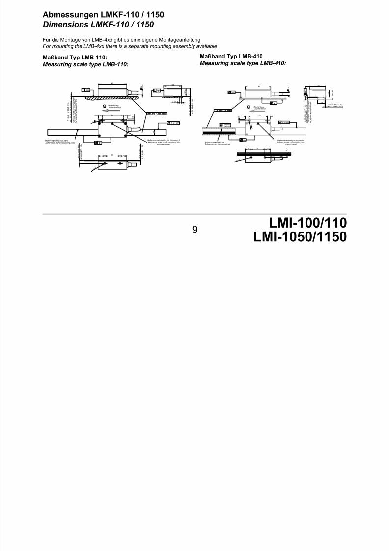
Abmessungen LMKF-110 / 1150Dimensions LMKF-110 / 1150
Maßband Typ LMB-110:Measuring scale type LMB-110:
Maßband Typ LMB-410Measuring scale type LMB-410:
1 0
36 =
2 , 5
2 x 4
=
Referenzmarke MaßbandReference mark measuring scale
LMB-110 / LMB-1150
Referenzmarke mittig im Abtastkopf Reference mark in the middle of the
scanning head 0,10,1
0,1/1000
26= =
2 x M 3
0 , 8
( L M B - 1
1 0 )
4 , 8
( L M K F - 1 1 0 )
0 , 6
( L M B - 1
1 5 0 )
49
0 , 1
5
0 , 1
( L M K F - 1
1 0 )
0 . 1
0 , 0
5 ( L M K F - 1
1 5 0 )
5 , 2
LMB-110 / LMB-1150
0,03
30
3 ±0,5
1 3
, 5
1 4
, 4 2 ( L M K F - 1 1 0 )
0,10,1
ZählrichtungCount direction
L
u f t s p a
l t m
i t F o
l i e e
i n g e s
t e l l t
A
i r g a p s e t w i t h s p a c e r f i l m
1 4
, 2 ( L M K F - 1
1 5 0 )
+
4 , 5
5 ( L M K F - 1
1 5 0 )
36= =
2 , 5
2 x
4
+ ZählrichtungCount direction
Referenzmarke MaßbandReference mark measuring scale
LMB-410 / LMB-4150
Referenzmarke mittig im Abtastkopf Reference mark in the middle of the
scanning head
0,1
0,1/1000
49
5 , 2
LMB-410 / LMB-4150
0,1
0,03
30
0 , 1
± 0 , 0
5 ( L M K F - 1 1 5 0 )
0 , 1
5 ± 0 , 1
( L M K F - 1 1 0 )
141±0,5 (LMKF-110)1 0,3 (LMKF-1150)
1 3 , 5
1 8 , 8
L u f t s p a l t m i t F o l i e e i n g e s t e l l t
A
i r g a p s e t w i t h s p a c e r f i l m
0 , 0
5
0 , 0
5
ReferenzReference
26= = 9 , 1
2 x M 3
0,1
0,1
Für die Montage von LMB-4xx gibt es eine eigene MontageanleitungFor mounting the LMB-4xx there is a separate mounting assembly available

7/17/2019 MA_LMI-100_110_1050_1150_20120613_web.pdf
http://slidepdf.com/reader/full/malmi-1001101050115020120613webpdf 10/24
LMI-100/110LMI-1050/1150
10
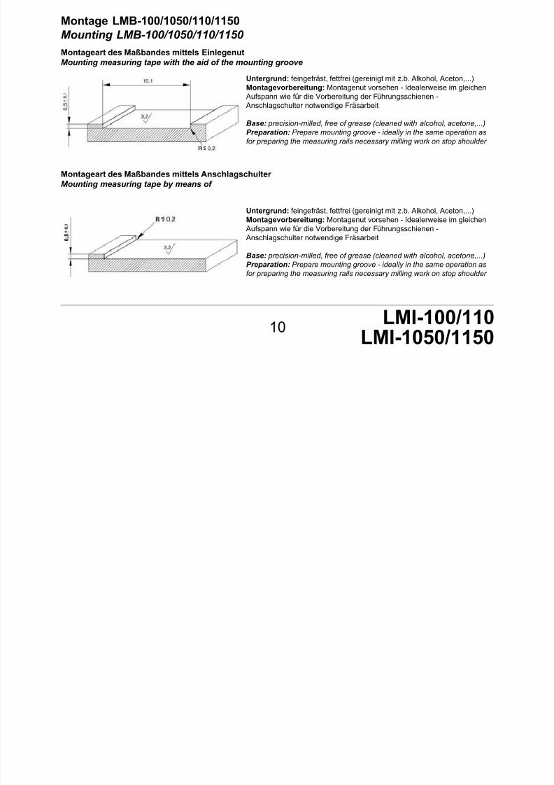
Montage LMB-100/1050/110/1150Mounting LMB-100/1050/110/1150
Montageart des Maßbandes mittels EinlegenutMounting measuring tape with the aid of the mounting groove
Untergrund: feingefräst, fettfrei (gereinigt mit z.b. Alkohol, Aceton,...)
Montagevorbereitung: Montagenut vorsehen - Idealerweise im gleichen Aufspann wie für die Vorbereitung der Führungsschienen - Anschlagschulter notwendige Fräsarbeit
Base: precision-milled, free of grease (cleaned with alcohol, acetone,...)
Preparation: Prepare mounting groove - ideally in the same operation as
for preparing the measuring rails necessary milling work on stop shoulder
Montageart des Maßbandes mittels Anschlagschulter Mounting measuring tape by means of
Untergrund: feingefräst, fettfrei (gereinigt mit z.b. Alkohol, Aceton,...)Montagevorbereitung: Montagenut vorsehen - Idealerweise im gleichen
Aufspann wie für die Vorbereitung der Führungsschienen - Anschlagschulter notwendige Fräsarbeit
Base: precision-milled, free of grease (cleaned with alcohol, acetone,...)
Preparation: Prepare mounting groove - ideally in the same operation as
for preparing the measuring rails necessary milling work on stop shoulder

7/17/2019 MA_LMI-100_110_1050_1150_20120613_web.pdf
http://slidepdf.com/reader/full/malmi-1001101050115020120613webpdf 11/24
LMI-100/110LMI-1050/1150
11
Montagnut bzw Montageschulter für Maßband auf Parallelität prüfen
Check parallel alignment of mounting groove or mounting shoulder for measuring tape
Mittels Messuhr die Höhendifferenz +/- 0,1 mm derEinlegenut prüfen
Use a dial gauge to check the height tolerance of
+/- 0,1 mm for the mounting groove
Überprüfung der Parallelität von 0,2 mm in Verfahrensrichtung
Check the parallel alignment of 0.2 mm in traverse direction

7/17/2019 MA_LMI-100_110_1050_1150_20120613_web.pdf
http://slidepdf.com/reader/full/malmi-1001101050115020120613webpdf 12/24
12
Montageart des Maßbandes mittels Hilfslineal Mounting the measuring tape by means of straight edge
Untergrund: feingefräst, fettfrei (gereinigt mit z.b. Alkohol, Aceton,...)
Base: precision-milled, free of grease (cleaned with alcohol, acetone,...)
Mittels Messuhr die Höhentoleranz +/- 0,1 mm derMontageäche prüfen
Use dial gauge to check the height tolerance of +/- 0,1
mm for mounting surface
Einstellung der Parallelität des Hilfslineals von 0,2 mmin Verfahrensrichtung
Set parallel alignment of straight edge of 0.2mm in
traverse direction
7/17/2019 MA_LMI-100_110_1050_1150_20120613_web.pdf
http://slidepdf.com/reader/full/malmi-1001101050115020120613webpdf 13/24
LMI-100/110LMI-1050/1150
13
Montage des Maßbandes LMB-100/110/1050/1150Mounting measuring tape LMB-100/110/1050/1150
Das Band darf nicht mit einem Radius < 300 mm gehoben werden. Während des ganzen Montageverfahrens daraufachten, dass keine Knickpunkte entstehen. Montageäche prüfen und mit größter Sorgfalt vorbereiten.
The measuring tape must be not bended with a radius < 300 mm. Take particular care that no bends or kinks occur du-
ring the entire mounting procedure. Check the mounting surface and prepare with the utmost care.
Das Maßband auspacken und auf die ganze Länge ach auegen.
Der Untergrund muss fettfrei sein (Reinigung mit z.B. Alkohol, Aceton, ...undfusselfreiem Papier oder Tuch)Die Abdeckfolie der Maßbandrückseite max 300mm abziehen.Das Maßband an das Lineal anschlagen und auf die Montageäche drücken.
Diesen Vorgang solange fortführen bis das gesamte Band montiert ist.
Unpack the measuring tape and lie at over the entire length.
The base must be free of grease (clean with alcohol, acetone etc. … and lint-
free paper or cloth)Pull off cover lm from back of measuring tape by max. 300mm
Fit the measuring tape against the straight edge and press onto the mounting
surface.
Carefully continue this procedure until the entire type is mounted.
Mittels einer Montagerolle wird das Maßband mit einer Kraft von ~250 N/cm²angedrückt.
ACHTUNG! Die Klebefestigkeit entsteht durch Druck. Die Endfestigkeit wirdbei ~20 °C nach 48 h erreicht.
Using a roller, press down the measuring tape by applying a force of ~250 N/ cm².
CAUTION! The adhesive strength is achieved by applying pressure. the naladhesive strength is achieved after 48h at ~20 C°.

7/17/2019 MA_LMI-100_110_1050_1150_20120613_web.pdf
http://slidepdf.com/reader/full/malmi-1001101050115020120613webpdf 14/24
14
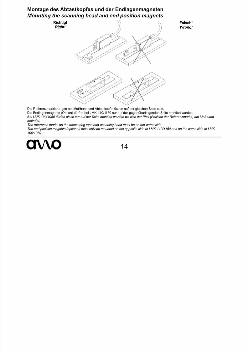
Montage des Abtastkopfes und der EndlagenmagnetenMounting the scanning head and end position magnets
Richtig!Right!
Falsch!Wrong!
Die Referenzmarkierungen am Maßband und Abtastkopf müssen auf der gleichen Seite sein.Die Endlagenmagnete (Option) dürfen bei LMK-110/1150 nur auf der gegenüberliegenden Seite montiert werden.
Bei LMK-100/1050 dürfen diese nur auf der Seite montiert werden wo sich der Pfeil (Position der Referenzmarke) am Maßbandbendet.
The reference marks on the measuring tape and scanning head must be on the same side.
The end position magnets (optional) must only be mounted on the opposite side at LMK-110/1150 and on the same side at LMK-
100/1050
7/17/2019 MA_LMI-100_110_1050_1150_20120613_web.pdf
http://slidepdf.com/reader/full/malmi-1001101050115020120613webpdf 15/24
LMI-100/110LMI-1050/1150
15
Montage des Abtastkopfes LMK-100/110/1050/1150Mounting scanning head LMK-100/110/1050/1150
LMK 100/1050 LMK 110/1150
Idealerweise wird ein Montagewinkel mit Langlöchern verwendet um die parallele Ausrichtung des Abtastkopfes in Messrichtung zuvereinfachen. Dieser muss auf 0,1 mm Parallelität zum montierten Maßband ausgerichtet werden.
A mounting bracket with slots should be ideally used to simplify parallel alignment of the scanning head in measurement direction.It must be aligned parallel to 0.1 mm with respect to the mounted measuring tape.
Der Abtastkopf wird mittig zumMaßband montiert, d.h. der seitliche
Abstand von Abtastkopf zum Maß-band beträgt max. 3 ± 0,5 mm beiLMK-110/1150 und max 1 ± 0,5 mmbei LMK-100/1050 über die gesam-te Messstrecke.
The scanning head is mounted
centrally with respect to the measu-
ring tape, i.e. the maximum lateral
distance from the scanning head tothe measuring tape is 3 ±0.5 mm
at LMK-110/1150 and 1 ± 0,5 mmat LMK-100/1050 over the entire
measuring section.

7/17/2019 MA_LMI-100_110_1050_1150_20120613_web.pdf
http://slidepdf.com/reader/full/malmi-1001101050115020120613webpdf 16/24
16
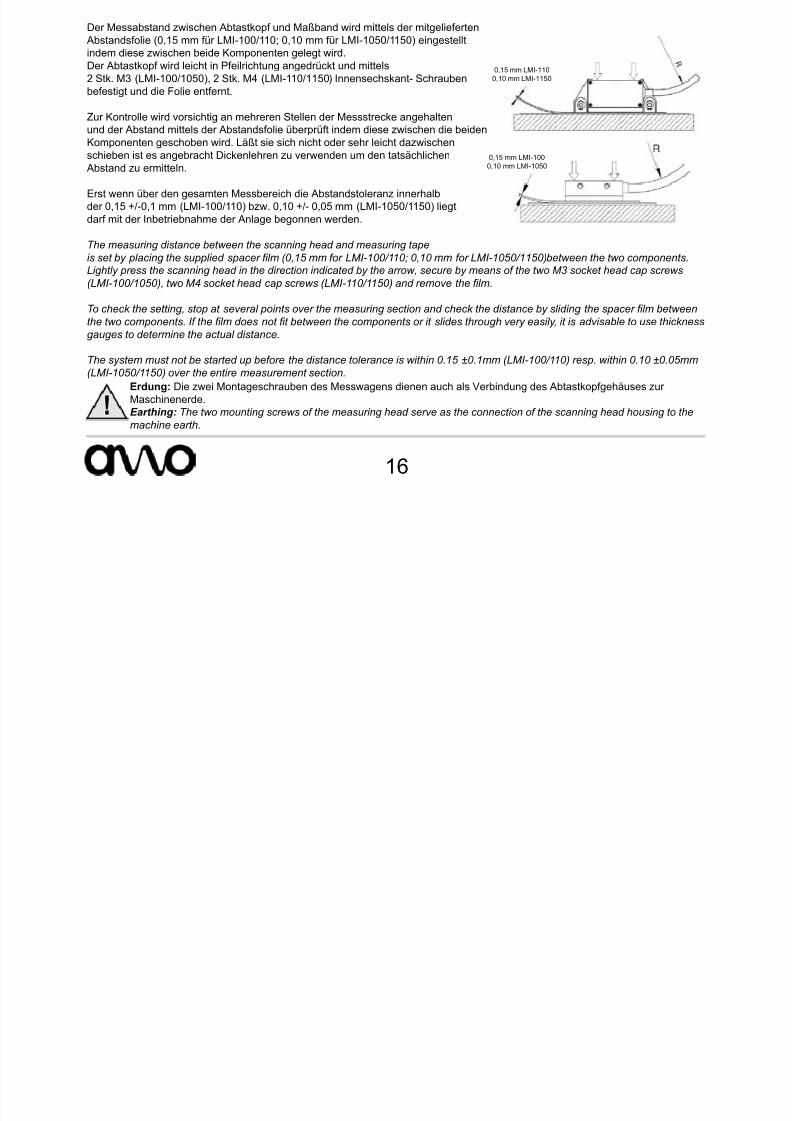
Der Messabstand zwischen Abtastkopf und Maßband wird mittels der mitgelieferten Abstandsfolie (0,15 mm für LMI-100/110; 0,10 mm für LMI-1050/1150) eingestelltindem diese zwischen beide Komponenten gelegt wird.Der Abtastkopf wird leicht in Pfeilrichtung angedrückt und mittels2 Stk. M3 (LMI-100/1050), 2 Stk. M4 (LMI-110/1150) Innensechskant- Schraubenbefestigt und die Folie entfernt.
Zur Kontrolle wird vorsichtig an mehreren Stellen der Messstrecke angehalten
und der Abstand mittels der Abstandsfolie überprüft indem diese zwischen die beidenKomponenten geschoben wird. Läßt sie sich nicht oder sehr leicht dazwischenschieben ist es angebracht Dickenlehren zu verwenden um den tatsächlichen
Abstand zu ermitteln.
Erst wenn über den gesamten Messbereich die Abstandstoleranz innerhalbder 0,15 +/-0,1 mm (LMI-100/110) bzw. 0,10 +/- 0,05 mm (LMI-1050/1150) liegtdarf mit der Inbetriebnahme der Anlage begonnen werden.
The measuring distance between the scanning head and measuring tape
is set by placing the supplied spacer lm (0,15 mm for LMI-100/110; 0,10 mm for LMI-1050/1150) between the two components.Lightly press the scanning head in the direction indicated by the arrow, secure by means of the two M3 socket head cap screws
(LMI-100/1050), two M4 socket head cap screws (LMI-110/1150) and remove the lm.
To check the setting, stop at several points over the measuring section and check the distance by sliding the spacer lm between
the two components. If the lm does not t between the components or it slides through very easily, it is advisable to use thickness
gauges to determine the actual distance.
The system must not be started up before the distance tolerance is within 0.15 ±0.1mm (LMI-100/110) resp. within 0.10 ±0.05mm
(LMI-1050/1150) over the entire measurement section.Erdung: Die zwei Montageschrauben des Messwagens dienen auch als Verbindung des Abtastkopfgehäuses zurMaschinenerde.Earthing: The two mounting screws of the measuring head serve as the connection of the scanning head housing to the
machine earth.
0,15 mm LMI-1100,10 mm LMI-1150
0,15 mm LMI-1000,10 mm LMI-1050
7/17/2019 MA_LMI-100_110_1050_1150_20120613_web.pdf
http://slidepdf.com/reader/full/malmi-1001101050115020120613webpdf 17/24
LMI-100/110LMI-1050/1150
17
Empfohlene Beschaltung der Nachfolgeelektronik
Recommended conguration of the subsequent electronics
A, B, RI: direkte Signalausgabe ohne Teilungsfaktor
A, B, RI: direct signal output without dividing factor
A´, B´, RI´: unterteilte Signalausgabe
A´, B´, RI´: divided signal output
Beschreibung der Ausgangssignale - 1VssDescription of the output signals - 1Vpp

7/17/2019 MA_LMI-100_110_1050_1150_20120613_web.pdf
http://slidepdf.com/reader/full/malmi-1001101050115020120613webpdf 18/24
18
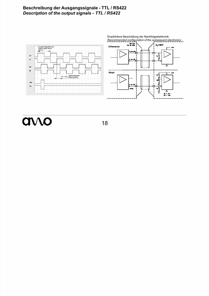
Empfohlene Beschaltung der NachfolgeelektronikRecommended conguration of the subsequent electronics
Beschreibung der Ausgangssignale - TTL / RS422Description of the output signals - TTL / RS422
7/17/2019 MA_LMI-100_110_1050_1150_20120613_web.pdf
http://slidepdf.com/reader/full/malmi-1001101050115020120613webpdf 19/24
LMI-100/110LMI-1050/1150
19
EndlagenfunktionLimit switch function
Der Endlagensensor bendet sich mittig am Abtastkopf (siehe dazu Montagezeichnung).
The limit switch sensor is located in the centre of the scanning head (see mounting drawing).
Die Endlagenausgänge sind als Open-Collector ausgeführt (Beschaltung siehe Abbildung).The limit switch output is implemented as an open-collector circuit (see circuit diagram).
Ausgangsbeschaltung Endlagenfunktion:Limit switch function output circuit:

7/17/2019 MA_LMI-100_110_1050_1150_20120613_web.pdf
http://slidepdf.com/reader/full/malmi-1001101050115020120613webpdf 20/24
20
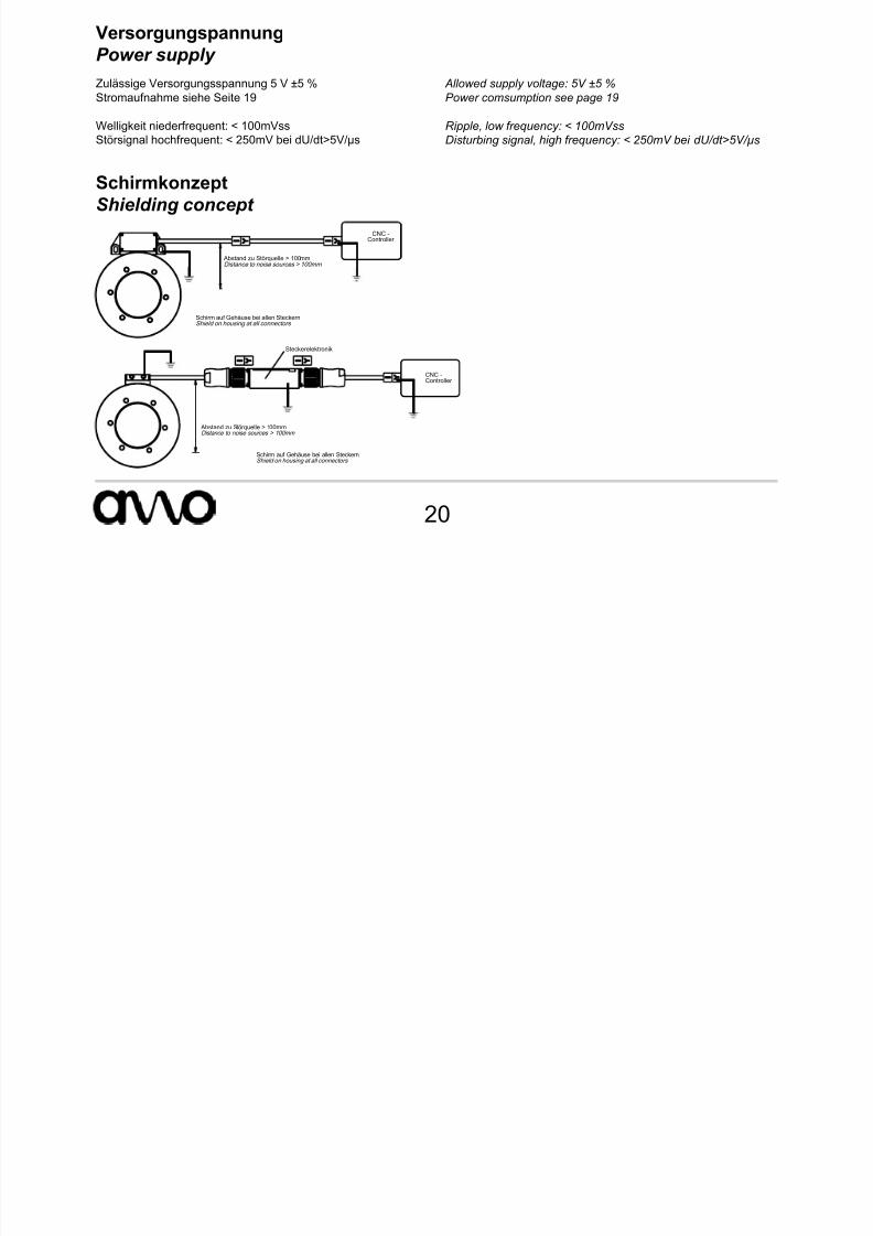
VersorgungspannungPower supply
SchirmkonzeptShielding concept
Zulässige Versorgungsspannung 5 V ±5 %Stromaufnahme siehe Seite 19
Welligkeit niederfrequent: < 100mVss
Störsignal hochfrequent: < 250mV bei dU/dt>5V/µs
Allowed supply voltage: 5V ±5 %
Power comsumption see page 19
Ripple, low frequency: < 100mVss
Disturbing signal, high frequency: < 250mV bei dU/dt>5V/µs
Abstand zu Störquelle > 100mmDistance to noise sources > 100mm
Schirm auf Gehäuse bei allen SteckernShield on housing at all connectors
CNC -Controller
Schirm auf Gehäuse bei allen SteckernShield on housing at all connectors
Abstand zu Störquelle > 100mmDistance to noise sources > 100mm
CNC -
Controller
Steckerelektronik
K b l

7/17/2019 MA_LMI-100_110_1050_1150_20120613_web.pdf
http://slidepdf.com/reader/full/malmi-1001101050115020120613webpdf 21/24
LMI-100/110LMI-1050/1150
21
KabelCable
Technische DatenTechnical data
Kabel für MesssystemCable for measuring system
VerlängerungskabelExtension cable
Mantel:Jacket:
PUR, hochexibel, schleppkettentauglich
PUR, high exible, suitable for energy chains
Durchmesser:Diameter:
5,3mm ~ 8mm
Adern:Wires:
5 (2 x 0,05) + 1 ( 2 x 0,14) mm 2 4 (2 x 0,14) + 2( 2 x 0,5) mm 2
Biegeradius:Bending radius:
Einmalbiegung:Single bending:
5 x d = 25mm 5 x d = 40mm
Dauerbiegung:Continuous bending:
10 x d = 50mm 10 x d = 80mm
Max. Länge:Max. length:
9m 50m
St k b l / Pl d ti i t
7/17/2019 MA_LMI-100_110_1050_1150_20120613_web.pdf
http://slidepdf.com/reader/full/malmi-1001101050115020120613webpdf 22/24
22
SUB-D Stecker 15-polig / SUB-D connector 15-pin
Sinus- 1 Vss oder Rechteck-Ausgangssignale TTLSine wave 1 Vpp or square wave output signals TTL
PIN 1 2 3 4 5 6 7 8 9 10 11 12 13 14 15
Signal A+ 0V B+ +5V – LR RI- LL A- 0V-Sensor B- 5V-Sensor – RI+ –Farbe grün blau braun rot – schwarz grau violett gelb blau-weiss weiss rot-weiss – rosa –Color green blue brown read – black gray violet yellow blue-white white red-white – pink –
Schirm am Gehäuse / Shield on housing
Steckerbelegungen / Plug and connection assignments
CONNEI-Typ Stecker bzw. Kupplung 12-polig - Metallkörper kunststoffummantelt
CONNEI connector adv. coupling 12-pin - plastic-coated metal body
Sinus- 1 Vss oder Rechteck-Ausgangssig<nale TTL / Sine wave 1 Vpp or square wave output signals TTL
PIN 1 2 3 4 5 6 7 8 9 10 11 12Signal B- 5V-Sensor RI+ RI- A+ A- LL B+ LR 0V 0V-Sensor +5VFarbe weiss rot-weiss rosa grau grün gelb violett braun schwarz blau blau-weiss rot
Color white red-white pink grey green yellow violet brown black blue blue-white redSchirm am Gehäuse / Shield on housing

7/17/2019 MA_LMI-100_110_1050_1150_20120613_web.pdf
http://slidepdf.com/reader/full/malmi-1001101050115020120613webpdf 23/24
LMI-100/110LMI-1050/1150
23
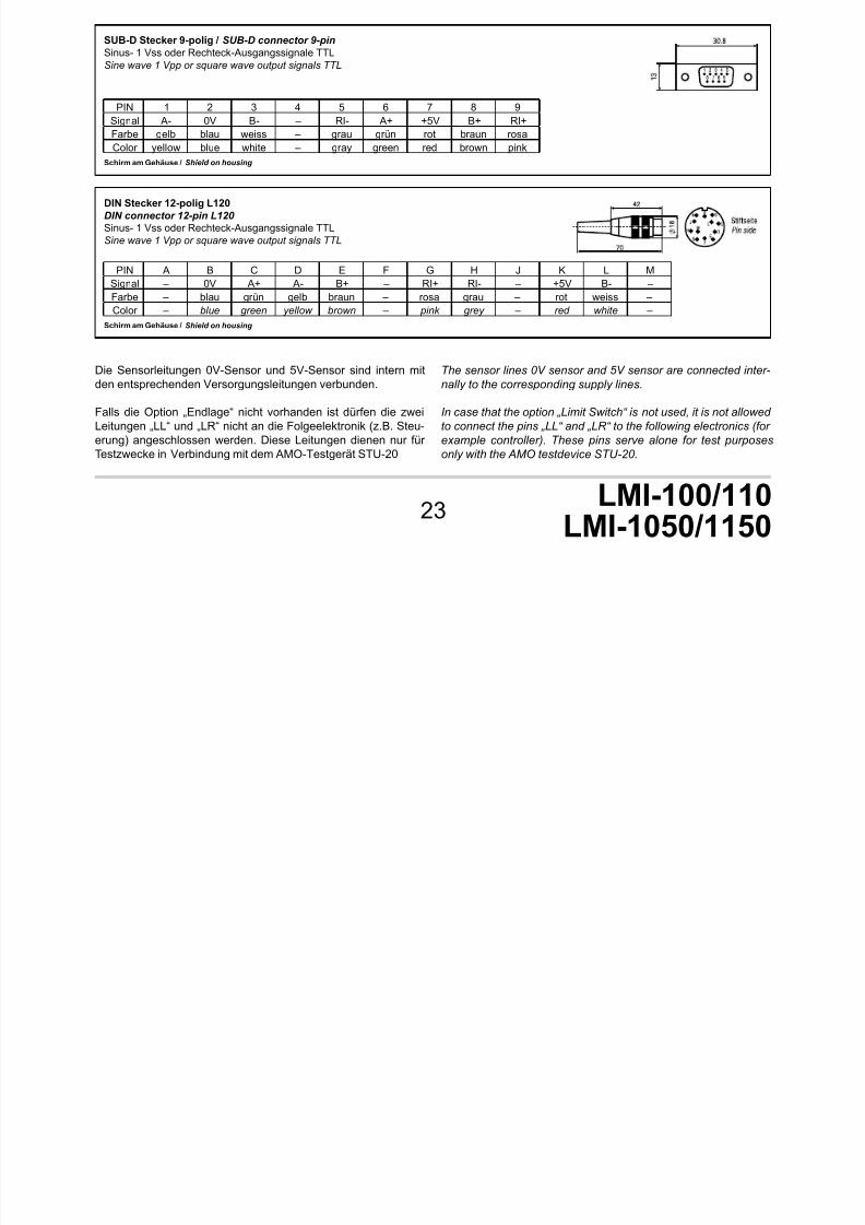
DIN Stecker 12-polig L120DIN connector 12-pin L120
Sinus- 1 Vss oder Rechteck-Ausgangssignale TTLSine wave 1 Vpp or square wave output signals TTL
PIN A B C D E F G H J K L MSignal – 0V A+ A- B+ – RI+ RI- – +5V B- –Farbe – blau grün gelb braun – rosa grau – rot weiss –Color – blue green yellow brown – pink grey – red white –
Schirm am Gehäuse / Shield on housing
SUB-D Stecker 9-polig / SUB-D connector 9-pin
Sinus- 1 Vss oder Rechteck-Ausgangssignale TTLSine wave 1 Vpp or square wave output signals TTL
PIN 1 2 3 4 5 6 7 8 9Signal A- 0V B- – RI- A+ +5V B+ RI+Farbe gelb blau weiss – grau grün rot braun rosaColor yellow blue white – gray green red brown pink
Schirm am Gehäuse / Shield on housing
Die Sensorleitungen 0V-Sensor und 5V-Sensor sind intern mitden entsprechenden Versorgungsleitungen verbunden.
Falls die Option „Endlage“ nicht vorhanden ist dürfen die zweiLeitungen „LL“ und „LR“ nicht an die Folgeelektronik (z.B. Steu-erung) angeschlossen werden. Diese Leitungen dienen nur fürTestzwecke in Verbindung mit dem AMO-Testgerät STU-20
The sensor lines 0V sensor and 5V sensor are connected inter-
nally to the corresponding supply lines.
In case that the option „Limit Switch“ is not used, it is not allowedto connect the pins „LL“ and „LR“ to the following electronics (for
example controller). These pins serve alone for test purposes
only with the AMO testdevice STU-20.
Headquarter

7/17/2019 MA_LMI-100_110_1050_1150_20120613_web.pdf
http://slidepdf.com/reader/full/malmi-1001101050115020120613webpdf 24/24
AMO GmbH
A-4963 St. Peter am Hart, Nöng 4 - Austria
Phone: +43 7722 658 56-0Fax: +43 7722 658 56-11
e-mail: [email protected]
www.amo-gmbh.com
Headquarter
Branches
Germany:
AMO GmbHZweigniederlassung Deutschland
Bussardstrasse 10D 78655 Dunningen
Phone: +49 7403 913 283Fax.: +49 7403 913 267
e-mail: [email protected]
USA:
AMO Corporation9580 Oak Ave Parkway Suite 7-162
Folsom, CA 95630
Phone: +1 916 791 2001
Fax: +1 916 720 0430
E-mail: [email protected]
Homepage: www.amosin.com
Italy:
AMO Italia s.r.l.20037 Paderno Dugnano MI - Italia
Via Gorizia 35
Phone: +39 029 108 23 41
E-mail: [email protected]
Homepage: www.amoitalia.it
Authorized distributors and sales partners in other countries:Please look at www.amo-gmbh.com
This document was created very carefully. If there are any technicalchanges, they will promptly updated in the documents on our homepagewww.amo-gmbh.com.With the publication of this mounting instruction all previous editionsbecome invalid.
Dieses Dokument wurde mit größter Sorgfalt erstellt. Sollte es zutechnischen Änderungen kommen, werden diese unverzüglich in denDokumenten auf unserer Homepage www.amo-gmbh.com aktualisert.Mit Erscheinen dieser Montageanleitung verlieren alle vorherigen Ausga-ben ihre Gültigkeit.