Embed Size (px)
Citation preview
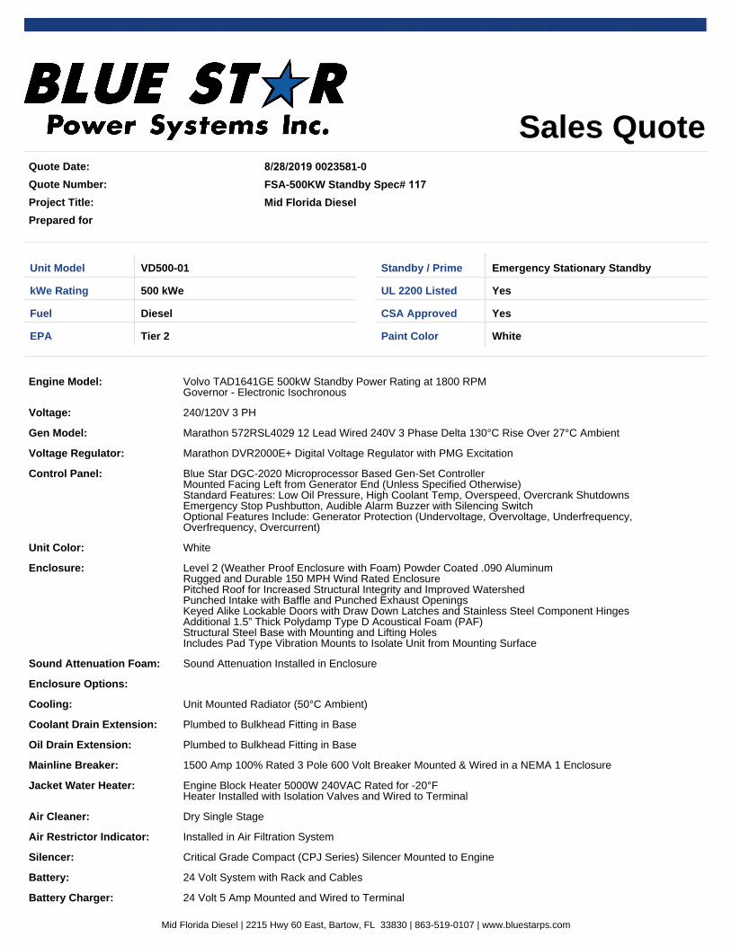
Mid Florida Diesel | 2215 Hwy 60 East, Bartow, FL 33830 | 863-519-0107 | www.bluestarps.com
MID FLORIDA DIESEL
2215 HIGHWAY 60 EAST
BARTOW, FL. 33830
(863) 519-0107 FAX (863) 519-0109 WWW.MIDFLORIDADIESEL.COM
Bill of Material For
Florida Sheriff Association Item #127 - 500KW GENERATOR PACKAGE
Blue Star Power Systems MODEL: (Qty. - 1) VD500-01
GENERATOR: 500 kW, 625 kVA VOLTAGE: 480 volt Three-Phase Engine Model: Volvo TAD1641GE 500kW Standby Power Rating at 1800 RPM
Selected Model Features Included: Isochronous Governor + / - .25% UL2200 EPA Tier II Certified
130 Degree Temperature Rise
Voltage: 480/277V 3 PH
Gen Model: Marathon 572RSL4027 12 Lead Wired 480V 3 Phase High Wye 130°C Rise Over 27°C Ambient Voltage Regulator: Marathon DVR2000E+ Digital Voltage Regulator with PMG Excitation
Control Panel: Blue Star DGC-2020 Microprocessor Based Gen-Set Controller Mounted Facing Left from Generator End (Unless Specified Otherwise) Standard Features: Low Oil Pressure, High Coolant Temp, Overspeed, Overcrank Shutdowns Emergency Stop Pushbutton, Audible Alarm Buzzer with Silencing Switch Optional Features Include: Generator Protection (Undervoltage, Overvoltage, Underfrequency, Overfrequency, Overcurrent)
Enclosure: Level 2 (Weather Proof Enclosure with Foam) Powder Coated .090 Aluminum Rugged and Durable 150 MPH Wind Rated Enclosure Pitched Roof for Increased Structural Integrity and Improved Watershed Punched Intake with Baffle and Punched Exhaust Openings Keyed Alike Lockable Doors with Draw Down Latches and Stainless Steel Component Hinges Additional 1.5” Thick Polydamp Type D Acoustical Foam (PAF) Structural Steel Base with Mounting and Lifting Holes Includes Pad Type Vibration Mounts to Isolate Unit from Mounting Surface Sound Attenuation Foam: Sound Attenuation Installed in Enclosure
Enclosure Options: -Cooling: Unit Mounted Radiator (50°C Ambient)-Coolant Drain Extension: Plumbed to Bulkhead Fitting in Base
Mid Florida Diesel | 2215 Hwy 60 East, Bartow, FL 33830 | 863-519-0107 | www.bluestarps.com
-Oil Drain Extension: Plumbed to Bulkhead Fitting in Base
Mainline Breaker: 800 Amp 3 Pole 600 Volt Breaker Mounted & Wired in a NEMA 1 Enclosure
Jacket Water Heater: Engine Block Heater 5000W 240VAC Rated for -20°F Heater Installed with Isolation Valves and Wired to Terminal
Air Cleaner: Dry Single Stage
Air Restrictor Indicator: Installed in Air Filtration System
Silencer: Critical Grade Compact (CPJ Series) Silencer Mounted to Engine
Battery: 24 Volt System with Rack and Cables
Battery Charger: 24 Volt 5 Amp Mounted and Wired to Terminal
Fuel Tank: 24 Hour / 900 Gallon UL 142 Listed Sub-Base Fuel Tank with Stub-up Area Double Wall Construction with Secondary Containment Standard Includes: Supply & Return Connections, Fuel Level Gauge, Fuel Leak Switch and Fill & Vent Plumbing
Factory Test: Standard Commercial Testing Includes: Verification of Alarm Shutdowns, Voltage Settings, Block Loading to Rated kWe and PF
Owner's Manual: Print Copy (Qty 1) Standard Warranty: 2 Year / 2000 Hour Limited
MISCELLANEOUS: Certified Factory Test Test Acceptance Run by Factory Trained Representative (Start Up)
Engineering Submittal 8/25-2020
Project Title FSA-500KW Standby Spec# 117
Quote Number: 0023581-0
Model: VD500-01
Mid Florida Diesel
Joe Antonini
2215 Hwy 60 East
Bartow FL 33830
Office: 863-519-0107
Cell: 863-944-0400
Email: [email protected]
Mid Florida Diesel | 2215 Hwy 60 East, Bartow, FL 33830 | 863-519-0107 | www.bluestarps.com
•
•
•
•
•
•
•
•
•
•
•
•
•
•
•
Table of Contents
Sales Quote
Specification Sheet
TAD1641GE 768 HP
Industrial Generators
DVR2000E+ Digital Voltage Regulator
DGC-2020 Gen-Set Controller
Gen-Set Enclosures
Sound Attenuation Foam
Radiators
CB CL Series Block Heaters
CPJ Series Critical Grade Silencers
Industrial Gen-Set Batteries
BC2405A Series Battery Chargers
Sub-Base Fuel Tanks
2yr 2000hr limited warranty
Mid Florida Diesel | 2215 Hwy 60 East, Bartow, FL 33830 | 863-519-0107 | www.bluestarps.com
Sales QuoteQuote Date:
Quote Number:
Project Title:
Prepared for
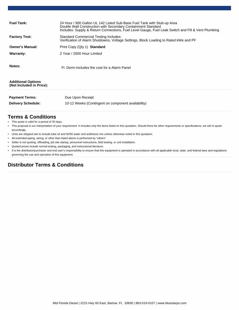
8/28/2019 0023581-0
FSA-500KW Standby Spec# 117 Mid Florida Diesel
Unit Model VD500-01 Standby / Prime Emergency Stationary Standby
kWe Rating 500 kWe UL 2200 Listed Yes
Fuel Diesel CSA Approved Yes
EPA Tier 2 Paint Color White
Engine Model: Volvo TAD1641GE 500kW Standby Power Rating at 1800 RPMGovernor - Electronic Isochronous
Voltage: 240/120V 3 PH
Gen Model: Marathon 572RSL4029 12 Lead Wired 240V 3 Phase Delta 130°C Rise Over 27°C Ambient
Voltage Regulator: Marathon DVR2000E+ Digital Voltage Regulator with PMG Excitation
Control Panel: Blue Star DGC-2020 Microprocessor Based Gen-Set ControllerMounted Facing Left from Generator End (Unless Specified Otherwise)Standard Features: Low Oil Pressure, High Coolant Temp, Overspeed, Overcrank ShutdownsEmergency Stop Pushbutton, Audible Alarm Buzzer with Silencing SwitchOptional Features Include: Generator Protection (Undervoltage, Overvoltage, Underfrequency,Overfrequency, Overcurrent)
Unit Color: White
Enclosure: Level 2 (Weather Proof Enclosure with Foam) Powder Coated .090 AluminumRugged and Durable 150 MPH Wind Rated EnclosurePitched Roof for Increased Structural Integrity and Improved WatershedPunched Intake with Baffle and Punched Exhaust OpeningsKeyed Alike Lockable Doors with Draw Down Latches and Stainless Steel Component HingesAdditional 1.5” Thick Polydamp Type D Acoustical Foam (PAF)Structural Steel Base with Mounting and Lifting HolesIncludes Pad Type Vibration Mounts to Isolate Unit from Mounting Surface
Sound Attenuation Foam: Sound Attenuation Installed in Enclosure
Enclosure Options:
Cooling: Unit Mounted Radiator (50°C Ambient)
Coolant Drain Extension: Plumbed to Bulkhead Fitting in Base
Oil Drain Extension: Plumbed to Bulkhead Fitting in Base
Mainline Breaker: 1500 Amp 100% Rated 3 Pole 600 Volt Breaker Mounted & Wired in a NEMA 1 Enclosure
Jacket Water Heater: Engine Block Heater 5000W 240VAC Rated for -20°FHeater Installed with Isolation Valves and Wired to Terminal
Air Cleaner: Dry Single Stage
Air Restrictor Indicator: Installed in Air Filtration System
Silencer: Critical Grade Compact (CPJ Series) Silencer Mounted to Engine
Battery: 24 Volt System with Rack and Cables
Battery Charger: 24 Volt 5 Amp Mounted and Wired to Terminal
Mid Florida Diesel | 2215 Hwy 60 East, Bartow, FL 33830 | 863-519-0107 | www.bluestarps.com
Fuel Tank: 24 Hour / 900 Gallon UL 142 Listed Sub-Base Fuel Tank with Stub-up AreaDouble Wall Construction with Secondary Containment StandardIncludes: Supply & Return Connections, Fuel Level Gauge, Fuel Leak Switch and Fill & Vent Plumbing
Factory Test: Standard Commercial Testing Includes:Verification of Alarm Shutdowns, Voltage Settings, Block Loading to Rated kWe and PF
Owner's Manual: Print Copy (Qty 1) Standard
Warranty: 2 Year / 2000 Hour Limited
Notes: Fl. Derm-Includes the cost for a Alarm Panel
Additional Options(Not Included in Price):
Payment Terms: Due Upon Receipt
Delivery Schedule: 10-12 Weeks (Contingent on component availability)
Terms & ConditionsThis quote is valid for a period of 30 days.•
This proposal is our interpretation of your requirement. It includes only the items listed on this quotation. Should there be other requirements or specifications, we will re-quote
accordingly.
•
Units are shipped wet to include lube oil and 50/50 water and antifreeze mix unless otherwise noted in this quotation.•
All extended piping, wiring, or other than listed above is performed by “others”.•
Seller is not quoting, offloading, job site startup, personnel instructions, field testing, or unit installation.•
Quoted prices include normal testing, packaging, and instructional literature.•
It is the distributor/purchaser and end user’s responsibility to ensure that this equipment is operated in accordance with all applicable local, state, and federal laws and regulations
governing the use and operation of this equipment.
•
Distributor Terms & Conditions
Mid Florida Diesel | 2215 Hwy 60 East, Bartow, FL 33830 | 863-519-0107 | www.bluestarps.com
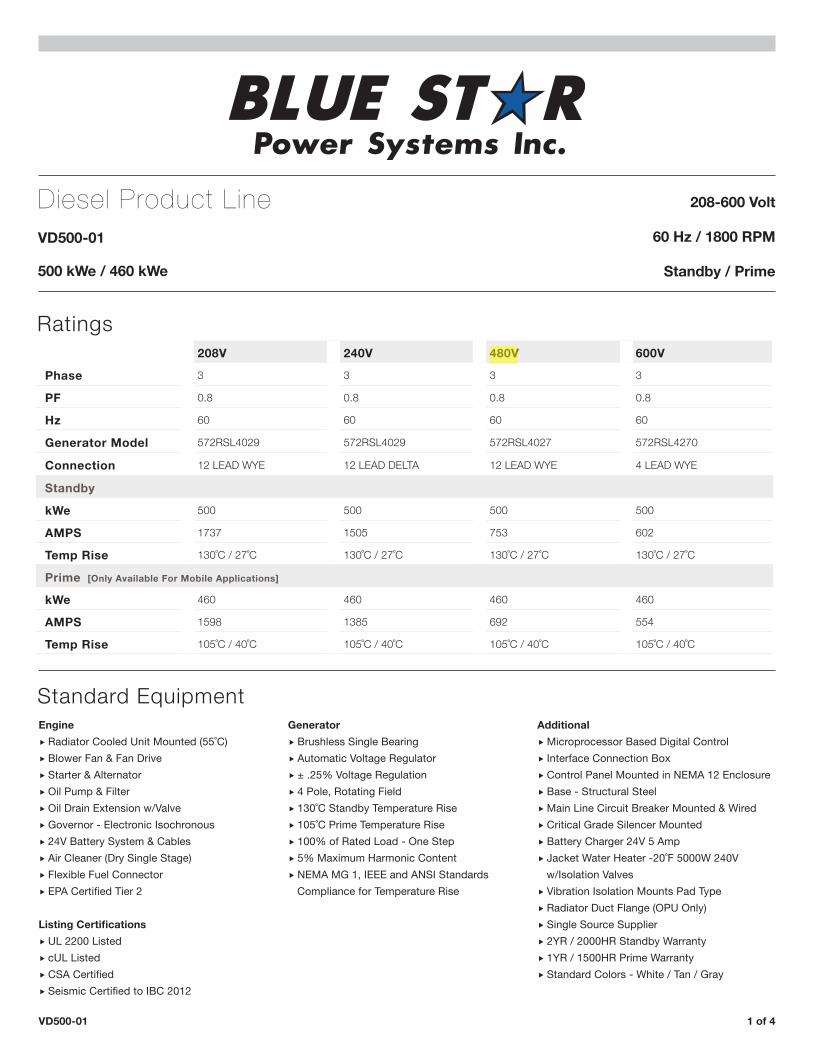
Diesel Product LineVD500-01
500 kWe / 460 kWe
208-600 Volt
60 Hz / 1800 RPM
Standby / Prime
Ratings208V 240V 480V 600V
Phase 3 3 3 3
PF 0.8 0.8 0.8 0.8
Hz 60 60 60 60
Generator Model 572RSL4029 572RSL4029 572RSL4027 572RSL4270
Connection 12 LEAD WYE 12 LEAD DELTA 12 LEAD WYE 4 LEAD WYE
Standby
kWe 500 500 500 500
AMPS 1737 1505 753 602
Temp Rise 130˚C / 27˚C 130˚C / 27˚C 130˚C / 27˚C 130˚C / 27˚C
Prime [Only Available For Mobile Applications]
kWe 460 460 460 460
AMPS 1598 1385 692 554
Temp Rise 105˚C / 40˚C 105˚C / 40˚C 105˚C / 40˚C 105˚C / 40˚C
Standard Equipment
VD500-01 1 of 4
Engine � Radiator Cooled Unit Mounted (55˚C) � Blower Fan & Fan Drive � Starter & Alternator � Oil Pump & Filter � Oil Drain Extension w/Valve � Governor - Electronic Isochronous � 24V Battery System & Cables � Air Cleaner (Dry Single Stage) � Flexible Fuel Connector � EPA Certified Tier 2
Listing Certifications � UL 2200 Listed � cUL Listed � CSA Certified � Seismic Certified to IBC 2012
Generator � Brushless Single Bearing � Automatic Voltage Regulator � ± .25% Voltage Regulation � 4 Pole, Rotating Field � 130˚C Standby Temperature Rise � 105˚C Prime Temperature Rise � 100% of Rated Load - One Step � 5% Maximum Harmonic Content � NEMA MG 1, IEEE and ANSI Standards Compliance for Temperature Rise
Additional � Microprocessor Based Digital Control � Interface Connection Box � Control Panel Mounted in NEMA 12 Enclosure � Base - Structural Steel � Main Line Circuit Breaker Mounted & Wired � Critical Grade Silencer Mounted � Battery Charger 24V 5 Amp � Jacket Water Heater -20˚F 5000W 240V w/Isolation Valves � Vibration Isolation Mounts Pad Type � Radiator Duct Flange (OPU Only) � Single Source Supplier � 2YR / 2000HR Standby Warranty � 1YR / 1500HR Prime Warranty � Standard Colors - White / Tan / Gray
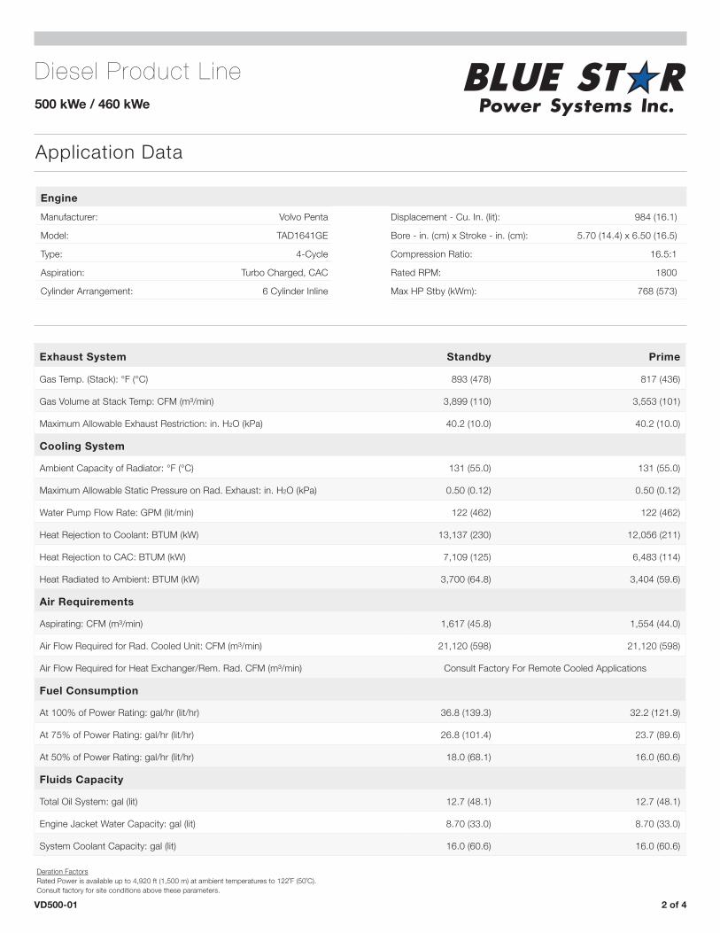
Diesel Product Line500 kWe / 460 kWe
Application Data
VD500-01 2 of 4
EngineManufacturer: Volvo Penta Displacement - Cu. In. (lit): 984 (16.1)
Model: TAD1641GE Bore - in. (cm) x Stroke - in. (cm): 5.70 (14.4) x 6.50 (16.5)
Type: 4-Cycle Compression Ratio: 16.5:1
Aspiration: Turbo Charged, CAC Rated RPM: 1800
Cylinder Arrangement: 6 Cylinder Inline Max HP Stby (kWm): 768 (573)
Exhaust System Standby Prime
Gas Temp. (Stack): °F (°C) 893 (478) 817 (436)
Gas Volume at Stack Temp: CFM (m³/min) 3,899 (110) 3,553 (101)
Maximum Allowable Exhaust Restriction: in. H2O (kPa) 40.2 (10.0) 40.2 (10.0)
Cooling System
Ambient Capacity of Radiator: °F (°C) 131 (55.0) 131 (55.0)
Maximum Allowable Static Pressure on Rad. Exhaust: in. H2O (kPa) 0.50 (0.12) 0.50 (0.12)
Water Pump Flow Rate: GPM (lit/min) 122 (462) 122 (462)
Heat Rejection to Coolant: BTUM (kW) 13,137 (230) 12,056 (211)
Heat Rejection to CAC: BTUM (kW) 7,109 (125) 6,483 (114)
Heat Radiated to Ambient: BTUM (kW) 3,700 (64.8) 3,404 (59.6)
Air Requirements
Aspirating: CFM (m³/min) 1,617 (45.8) 1,554 (44.0)
Air Flow Required for Rad. Cooled Unit: CFM (m³/min) 21,120 (598) 21,120 (598)
Air Flow Required for Heat Exchanger/Rem. Rad. CFM (m³/min) Consult Factory For Remote Cooled Applications
Fuel Consumption
At 100% of Power Rating: gal/hr (lit/hr) 36.8 (139.3) 32.2 (121.9)
At 75% of Power Rating: gal/hr (lit/hr) 26.8 (101.4) 23.7 (89.6)
At 50% of Power Rating: gal/hr (lit/hr) 18.0 (68.1) 16.0 (60.6)
Fluids Capacity
Total Oil System: gal (lit) 12.7 (48.1) 12.7 (48.1)
Engine Jacket Water Capacity: gal (lit) 8.70 (33.0) 8.70 (33.0)
System Coolant Capacity: gal (lit) 16.0 (60.6) 16.0 (60.6)
Deration FactorsRated Power is available up to 4,920 ft (1,500 m) at ambient temperatures to 122˚F (50˚C). Consult factory for site conditions above these parameters.
Diesel Product Line500 kWe / 460 kWe
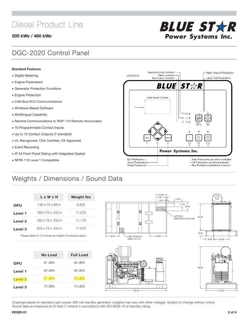
DGC-2020 Control Panel
VD500-01 3 of 4
Weights / Dimensions / Sound Data
L x W x H Weight lbs
OPU 140 x 72 x 98 in 9,425
Level 1 180 x 72 x 103 in 11,075
Level 2 180 x 72 x 103 in 11,175
Level 3 225 x 72 x 103 in 11,575
No Load Full Load
OPU 91 dBA 94 dBA
Level 1 86 dBA 89 dBA
Level 2 81 dBA 83 dBA
Level 3 73 dBA 75 dBA
Standard Features
� Digital Metering
� Engine Parameters
� Generator Protection Functions
� Engine Protection
� CAN Bus ECU Communications
� Windows-Based Software
� Multilingual Capability
� Remote Communications to RDP-110 Remote Annunciator
� 16 Programmable Contact Inputs
� Up to 15 Contact Outputs (7 standard)
� UL Recognized, CSA Certified, CE Approved
� Event Recording
� IP 54 Front Panel Rating with Integrated Gasket
� NFPA 110 Level 1 Compatible
Drawings based on standard open power 480 volt standby generator. Lengths may vary with other voltages. Subject to change without notice.Sound data as measured at 23 feet (7 meters) in accordance with ISO 8528-10 at standby rating.
Please allow 6-12 inches for height of exhaust stack.
Diesel Product Line500 kWe / 460 kWe
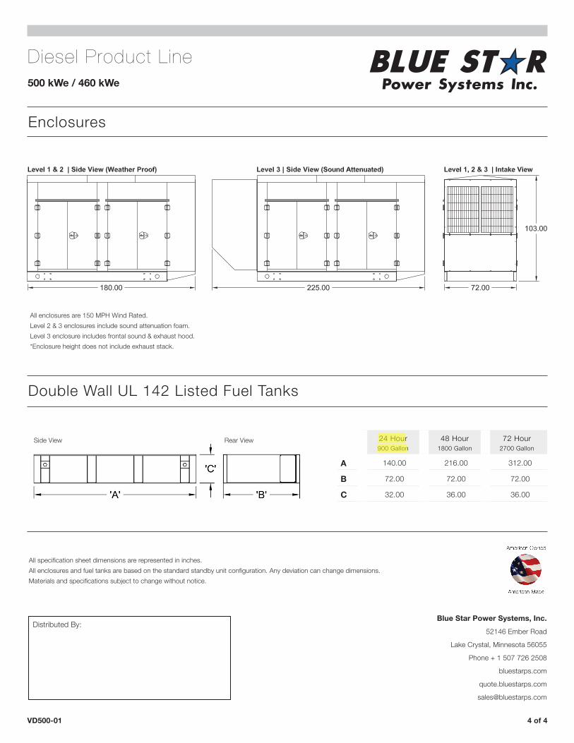
Enclosures
VD500-01 4 of 4
Double Wall UL 142 Listed Fuel Tanks
All specification sheet dimensions are represented in inches.All enclosures and fuel tanks are based on the standard standby unit configuration. Any deviation can change dimensions.Materials and specifications subject to change without notice.
Side View Rear View
Distributed By:Blue Star Power Systems, Inc.
52146 Ember Road
Lake Crystal, Minnesota 56055
Phone + 1 507 726 2508
bluestarps.com
quote.bluestarps.com
All enclosures are 150 MPH Wind Rated.Level 2 & 3 enclosures include sound attenuation foam. Level 3 enclosure includes frontal sound & exhaust hood.*Enclosure height does not include exhaust stack.
24 Hour 900 Gallon
48 Hour 1800 Gallon
72 Hour 2700 Gallon
A 140.00 216.00 312.00
B 72.00 72.00 72.00
C 32.00 36.00 36.00
1 of 13
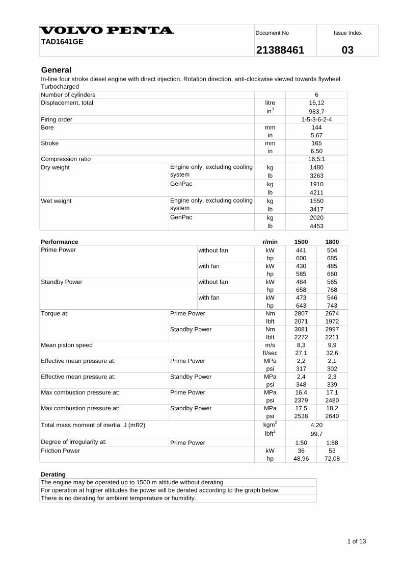
General
litre
in3
mm
in
mm
in
Dry weight kg
lb
kg
lb
Wet weight kg
lb
kg
lb
r/min 1500 1800
without fan kW 441 504
hp 600 685
with fan kW 430 485
hp 585 660
without fan kW 484 565
hp 658 768
with fan kW 473 546
hp 643 743
Torque at: Nm 2807 2674
lbft 2071 1972
Nm 3081 2997
lbft 2272 2211
m/s 8,3 9,9
ft/sec 27,1 32,6
MPa 2,2 2,1
psi 317 302
MPa 2,4 2,3
psi 348 339
MPa 16,4 17,1
psi 2379 2480
MPa 17,5 18,2
psi 2538 2640
kgm2
lbft2
1:50 1:88
kW 36 53
hp 48,96 72,08
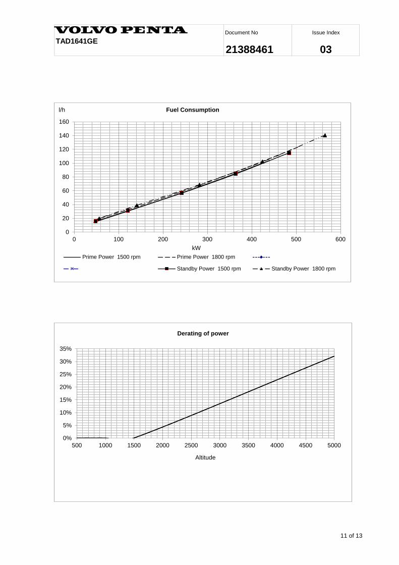
Derating
The engine may be operated up to 1500 m altitude without derating .
For operation at higher altitudes the power will be derated according to the graph below.
There is no derating for ambient temperature or humidity.
Issue Index
03TAD1641GE
Document No
21388461
1550
Performance
2020
Displacement, total
983,7
1-5-3-6-2-4Firing order
6,50
Compression ratio 16,5:1
4453
1480
3263
Prime Power
Engine only, excluding cooling
system
GenPac
Engine only, excluding cooling
system
GenPac
3417
1910
4211
Standby Power
Mean piston speed
Total mass moment of inertia, J (mR2)
Friction Power
Standby Power
Standby Power
Bore
Stroke
144
5,67
165
Number of cylinders
16,12
Prime Power
In-line four stroke diesel engine with direct injection. Rotation direction, anti-clockwise viewed towards flywheel.
Turbocharged
99,7
Prime Power
6
Prime Power
Degree of irregularity at:
Effective mean pressure at:
Max combustion pressure at:
Prime Power
Standby Power
Effective mean pressure at:
4,20
Max combustion pressure at:
2 of 13
Issue Index
03TAD1641GE
Document No
21388461
r/min 1500 1800
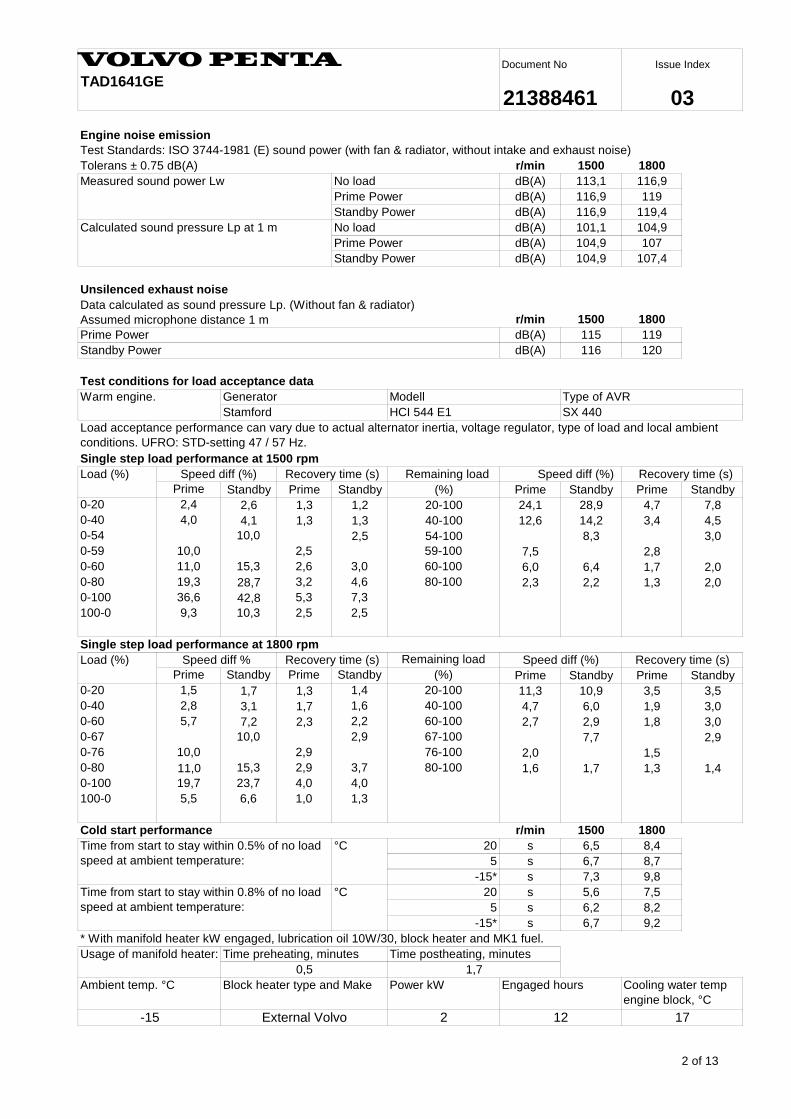
dB(A) 113,1 116,9
dB(A) 116,9 119
dB(A) 116,9 119,4
No load dB(A) 101,1 104,9
dB(A) 104,9 107
dB(A) 104,9 107,4
Unsilenced exhaust noise
r/min 1500 1800
dB(A) 115 119
dB(A) 116 120
Remaining load
Prime Standby Prime Standby (%) Prime Standby Prime Standby
0-20 2,4 2,6 1,3 1,2 20-100 24,1 28,9 4,7 7,8
0-40 4,0 4,1 1,3 1,3 40-100 12,6 14,2 3,4 4,5
0-54 10,0 2,5 54-100 8,3 3,0
0-59 10,0 2,5 59-100 7,5 2,8
0-60 11,0 15,3 2,6 3,0 60-100 6,0 6,4 1,7 2,0
0-80 19,3 28,7 3,2 4,6 80-100 2,3 2,2 1,3 2,0
0-100 36,6 42,8 5,3 7,3
100-0 9,3 10,3 2,5 2,5
Remaining load
Prime Standby Prime Standby (%) Prime Standby Prime Standby
0-20 1,5 1,7 1,3 1,4 20-100 11,3 10,9 3,5 3,5
0-40 2,8 3,1 1,7 1,6 40-100 4,7 6,0 1,9 3,0
0-60 5,7 7,2 2,3 2,2 60-100 2,7 2,9 1,8 3,0
0-67 10,0 2,9 67-100 7,7 2,9
0-76 10,0 2,9 76-100 2,0 1,5
0-80 11,0 15,3 2,9 3,7 80-100 1,6 1,7 1,3 1,4
0-100 19,7 23,7 4,0 4,0
100-0 5,5 6,6 1,0 1,3
Cold start performance r/min 1500 1800
20 s 6,5 8,4
5 s 6,7 8,7
-15* s 7,3 9,8
20 s 5,6 7,5
5 s 6,2 8,2
-15* s 6,7 9,2
* With manifold heater kW engaged, lubrication oil 10W/30, block heater and MK1 fuel.
2
Engine noise emission
Tolerans ± 0.75 dB(A)
Test Standards: ISO 3744-1981 (E) sound power (with fan & radiator, without intake and exhaust noise)
SX 440
Test conditions for load acceptance data
Prime Power
Standby Power
0,5
Speed diff (%)Recovery time (s)
Load acceptance performance can vary due to actual alternator inertia, voltage regulator, type of load and local ambient
conditions. UFRO: STD-setting 47 / 57 Hz.
Standby Power
Single step load performance at 1500 rpm
Recovery time (s)
Stamford
Recovery time (s)
Speed diff %
Speed diff (%)
-15
Single step load performance at 1800 rpm
Load (%)
External Volvo
Time preheating, minutes Time postheating, minutes
Cooling water temp
engine block, °C
Block heater type and Make
Measured sound power Lw
Load (%)
12
No load
Generator Modell Type of AVRWarm engine.
Recovery time (s) Speed diff (%)
Calculated sound pressure Lp at 1 m
Prime Power
Standby Power
Prime Power
Data calculated as sound pressure Lp. (Without fan & radiator)
Assumed microphone distance 1 m
Usage of manifold heater:
HCI 544 E1
Engaged hours
1,7
17
°CTime from start to stay within 0.5% of no load
speed at ambient temperature:
°CTime from start to stay within 0.8% of no load
speed at ambient temperature:
Ambient temp. °C Power kW
3 of 13
Issue Index
03TAD1641GE
Document No
21388461
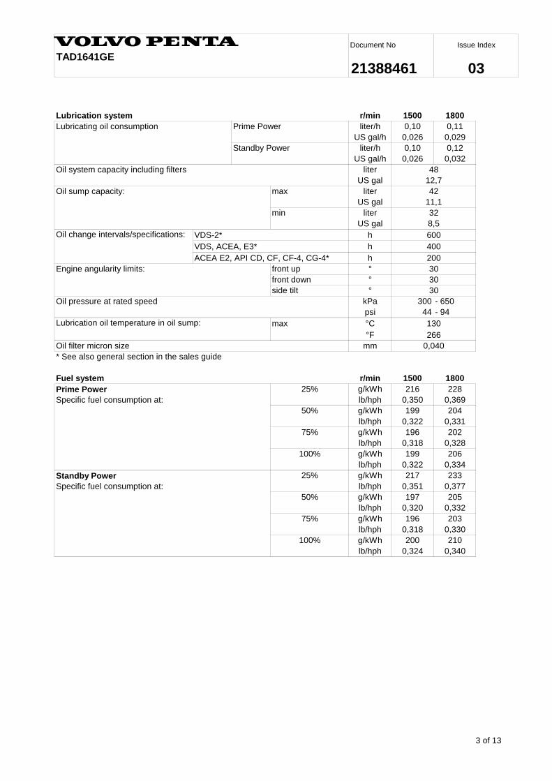
r/min 1500 1800
liter/h 0,10 0,11
US gal/h 0,026 0,029
liter/h 0,10 0,12
US gal/h 0,026 0,032
liter
US gal
max liter
US gal
min liter
US gal
h
h
h
front up °
front down °
side tilt °
kPa 300 - 650
psi 44 - 94
max °C
°F
Oil filter micron size mm
Fuel system r/min 1500 1800
25% g/kWh 216 228
lb/hph 0,350 0,369
50% g/kWh 199 204
lb/hph 0,322 0,331
75% g/kWh 196 202
lb/hph 0,318 0,328
100% g/kWh 199 206
lb/hph 0,322 0,334
25% g/kWh 217 233
lb/hph 0,351 0,377
50% g/kWh 197 205
lb/hph 0,320 0,332
75% g/kWh 196 203
lb/hph 0,318 0,330
100% g/kWh 200 210
lb/hph 0,324 0,340
266
42
30
VDS-2*
130
200
400
30
30
8,5
600
0,040
12,7
11,1
Oil sump capacity:
Oil system capacity including filters
Lubricating oil consumption
Standby Power
Prime Power
Lubrication system
32
48
VDS, ACEA, E3*
Specific fuel consumption at:
Standby Power
Specific fuel consumption at:
Prime Power
Engine angularity limits:
Oil change intervals/specifications:
ACEA E2, API CD, CF, CF-4, CG-4*
Lubrication oil temperature in oil sump:
* See also general section in the sales guide
Oil pressure at rated speed
4 of 13
Issue Index
03TAD1641GE
Document No
21388461
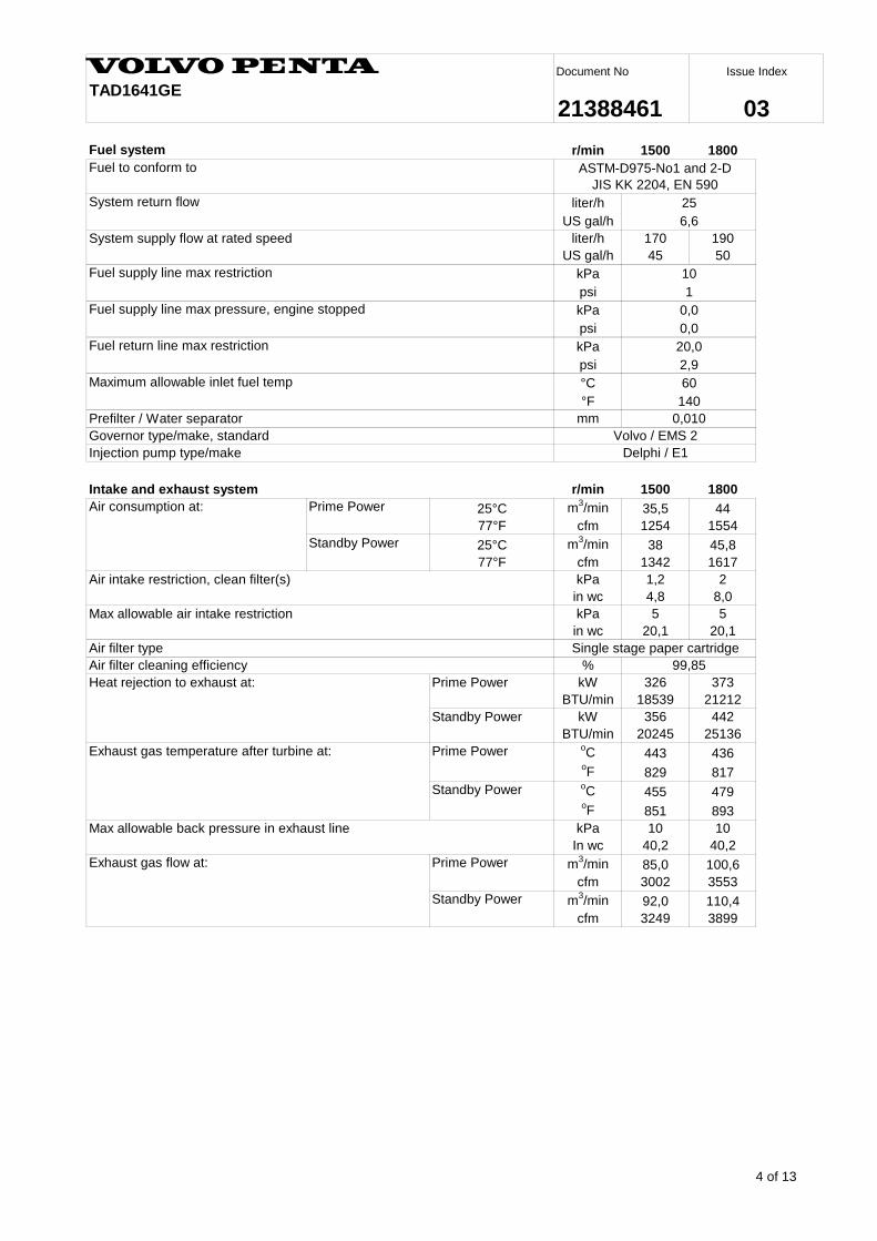
r/min 1500 1800
liter/h
US gal/h
liter/h 170 190
US gal/h 45 50
kPa
psi
kPa
psi
kPa
psi
°C
°F
mm
Intake and exhaust system r/min 1500 1800
25°C m3/min 35,5 44
77°F cfm 1254 1554
25°C m3/min 38 45,8
77°F cfm 1342 1617
kPa 1,2 2
in wc 4,8 8,0
kPa 5 5
in wc 20,1 20,1
%
kW 326 373
BTU/min 18539 21212
kW 356 442
BTU/min 20245 25136oC 443 436
oF 829 817
oC 455 479
oF 851 893
kPa 10 10
In wc 40,2 40,2
m3/min 85,0 100,6
cfm 3002 3553
m3/min 92,0 110,4
cfm 3249 3899
System return flow 25
6,6
Fuel supply line max restriction
1
10
0,0
99,85
Heat rejection to exhaust at:
Exhaust gas temperature after turbine at:
Max allowable back pressure in exhaust line
Single stage paper cartridge
System supply flow at rated speed
Injection pump type/make
ASTM-D975-No1 and 2-D
JIS KK 2204, EN 590
Delphi / E1
0,010
Governor type/make, standard
Fuel to conform to
Fuel supply line max pressure, engine stopped
Prefilter / Water separator
Air intake restriction, clean filter(s)
Max allowable air intake restriction
Air consumption at:
Air filter type
Prime Power
Standby Power
Fuel system
Volvo / EMS 2
0,0
Maximum allowable inlet fuel temp 60
140
Prime Power
Standby Power
Prime Power
Standby Power
Prime Power
Standby Power
Air filter cleaning efficiency
Exhaust gas flow at:
Fuel return line max restriction 20,0
2,9
5 of 13
Issue Index
03TAD1641GE
Document No
21388461
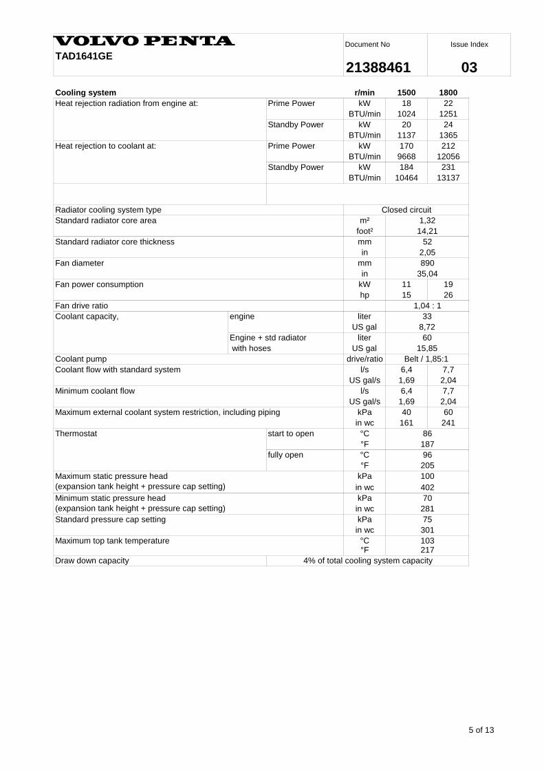
r/min 1500 1800
kW 18 22
BTU/min 1024 1251
kW 20 24
BTU/min 1137 1365
kW 170 212
BTU/min 9668 12056
kW 184 231
BTU/min 10464 13137
m²
foot²
mm
in
mm
in
kW 11 19
hp 15 26
liter
US gal
liter
US gal
drive/ratio
l/s 6,4 7,7
US gal/s 1,69 2,04
l/s 6,4 7,7
US gal/s 1,69 2,04
kPa 40 60
in wc 161 241
start to open °C
°F
fully open °C
°F
kPa
in wc
kPa
in wc
kPa
in wc
°C°F
8,72
281
205
402
86
187
Coolant capacity,
Minimum static pressure head
(expansion tank height + pressure cap setting)
with hoses
engine
Coolant pump
Fan power consumption
Fan drive ratio
35,04
Standard radiator core thickness 52
1,04 : 1
33
Engine + std radiator 60
15,85
Belt / 1,85:1
Thermostat
96
217
Minimum coolant flow
Maximum external coolant system restriction, including piping
Closed circuit
Standard radiator core area 1,32
14,21
2,05
890
Radiator cooling system type
Heat rejection to coolant at:
Standby Power
Prime Power
Heat rejection radiation from engine at:
Cooling system
Draw down capacity 4% of total cooling system capacity
103
70
Coolant flow with standard system
100
Standard pressure cap setting 75
301
Maximum static pressure head
(expansion tank height + pressure cap setting)
Maximum top tank temperature
Prime Power
Standby Power
Fan diameter
6 of 13
Issue Index
03TAD1641GE
Document No
21388461
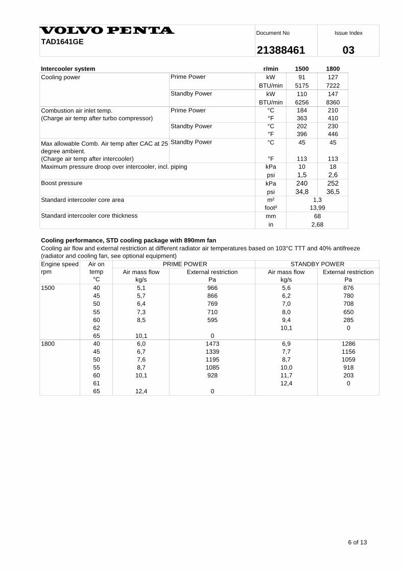
r/min 1500 1800
kW 91 127
BTU/min 5175 7222
kW 110 147
BTU/min 6256 8360
°C 184 210
°F 363 410
°C 202 230
°F 396 446
°C 45 45
°F 113 113
kPa 10 18
psi 1,5 2,6
kPa 240 252
psi 34,8 36,5m²
foot²
mm
in
Cooling performance, STD cooling package with 890mm fan
1500 40
45
50
55
60
62
65
1800 40
45
50
55
60
61
65
0
876
Maximum pressure droop over intercooler, incl. piping
7,0
8,0
6,4
7,3
966
769
Standby Power
8,7
1156
0
6,9
1339
10,1
0
928
6,0
8,5
10,1
1195
9,4
10,1
1473
595
7,7
5,1
7806,2
5,6
866
Engine speed
rpm
Air on
temp
°C
5,7
PRIME POWER
Prime Power
Cooling power
Boost pressure
STANDBY POWER
Air mass flow
kg/s
Air mass flow
kg/s
External restriction
Pa
7,6
708
650
Combustion air inlet temp.
(Charge air temp after turbo compressor)
0
Max allowable Comb. Air temp after CAC at 25
degree ambient.
(Charge air temp after intercooler)
8,7
Standby Power
Standby Power
Standard intercooler core area
Prime Power
6,7
1286
11,7 203
1085
Intercooler system
12,4
710
Standard intercooler core thickness
1,3
12,4
13,99
68
2,68
1059
918
285
10,0
Cooling air flow and external restriction at different radiator air temperatures based on 103°C TTT and 40% antifreeze
(radiator and cooling fan, see optional equipment)
External restriction
Pa
7 of 13
Issue Index
03TAD1641GE
Document No
21388461
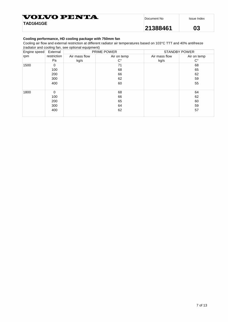
Cooling performance, HD cooling package with 750mm fan
1500 0
100
200
300
400
1800 0
100
200
300
400
60
66
57
64 59
62
62
65
68 64
62
59
55
66
62
68
65
71
68
External
restriction
Pa
PRIME POWER
Air mass flow
kg/s
Air on temp
C°
Air mass flow
kg/s
Air on temp
C°
STANDBY POWER
60
Cooling air flow and external restriction at different radiator air temperatures based on 103°C TTT and 40% antifreeze
(radiator and cooling fan, see optional equipment)
Engine speed
rpm
8 of 13
Issue Index
03TAD1641GE
Document No
21388461
Functionallity
Governor mode
Governor droop
Low Idle speed select
Stop function
Lamp test
Pre-heat on ignition
Default setting
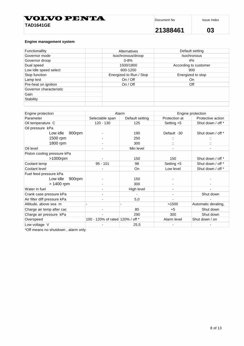
125
Low idle 900rpm 190
1500 rpm 250
1800 rpm 300
Min level
>1000rpm 150
98
On
Low idle 900rpm 150
> 1400 rpm 300
High level
-
5,0
-
80
290
Overspeed 120% / off *
25,5
*Off means no shutdown , alarm only.
- -
Fuel feed pressure kPa
Charge air pressure kPa
Low voltage V -
Alarm level Shut down / on
Shut down
-
Engine management system
Alarm Engine protectionEngine protection
Gain
Oil pressure kPa
Piston cooling pressure kPa
- +5
Oil level
-
Coolant temp
Coolant level
Water in fuel
300 Shut down
- 150 Shut down / off *
-
Shut down / off *
Selectable span Protection at Protective action
Oil temperature C 120 - 130 Setting +5 Shut down / off *
On / Off
-
::
::
-
-
::
Low level
Shut down / off *95 - 101
-
Charge air temp after cac
Dual speed
0-8%
Governor characteristic
100 - 120% of rated
Altitude, above sea m
Parameter
Off
Energized to stop
900
4%
Alternatives Default setting
Isochronous/droop
1500/1800 According to customer
Isochronous
600-1200
- Default -30 Shut down / off *
On
Energized to Run / Stop
On / Off
- --
-
-
-
-
-
Setting +5
::
-
Air filter diff pressure kPa
- Shut down-Crank case pressure kPa
- - -
Automatic derating,
-
Stability
>1500
9 of 13
Issue Index
03TAD1641GE
Document No
21388461
r/min 1500 1800
make/output Amp
tacho output Hz/alt. Rev
drive ratio
make
type
kW
pull current Amp
hold current Amp
flywheel
starter motor
Amp
Amp
rpm
max Ah
min at +5°C Ah
kW
Amp
r/min 1500 1800
Nm
lbft
kW - -
hp
kW - -
hp
kW - -
hp
Nm
lbft
Nm
lbft
Nm
lbft
N
lbf
Max allowed bending moment in flywheel housing 15000
11063
-
1
-
24V / insulated from earth
6
1,31:1 / anti-clockwise
118
74
160
100
2,3
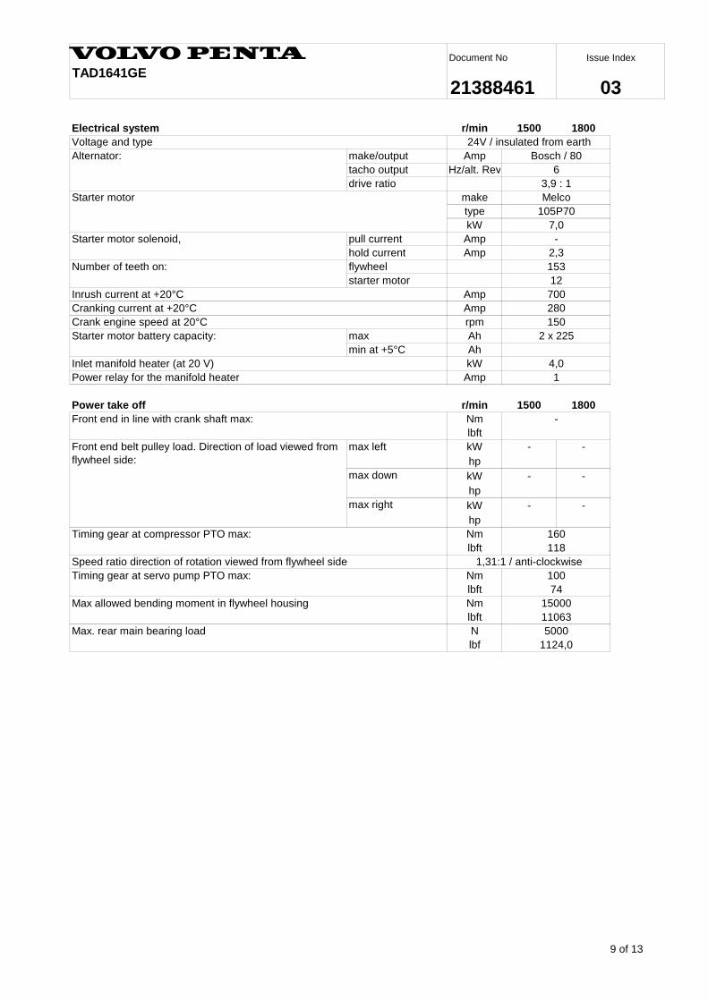
Electrical system
Starter motor Melco
105P70
7,0
Voltage and type
Bosch / 80Alternator:
3,9 : 1
2 x 225
150
153
12
Inrush current at +20°C 700
280
4,0
Power relay for the manifold heater
Front end in line with crank shaft max:
max down
Cranking current at +20°C
Starter motor solenoid,
Front end belt pulley load. Direction of load viewed from
flywheel side:
Crank engine speed at 20°C
max left
Speed ratio direction of rotation viewed from flywheel side
max right
Timing gear at servo pump PTO max:
Number of teeth on:
Power take off
Inlet manifold heater (at 20 V)
Timing gear at compressor PTO max:
Starter motor battery capacity:
Max. rear main bearing load 5000
1124,0
10 of 13
Issue Index
03TAD1641GE
Document No
21388461
0
0,1
0,2
0,3
0,4
0,5
0,6
0,7
0,8
0,9
1
0 100 200 300 400 500 600
BSU calculated value
kW
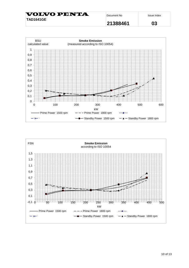
Smoke Emission (measured according to ISO 10054)
Prime Power 1500 rpm Prime Power 1800 rpm
Standby Power 1500 rpm Standby Power 1800 rpm
-0,1
0,1
0,3
0,5
0,7
0,9
1,1
1,3
1,5
0 50 100 150 200 250 300 350 400 450 500
FSN
kW
Smoke Emission according to ISO 10054
Prime Power 1500 rpm Prime Power 1800 rpm
Standby Power 1500 rpm Standby Power 1800 rpm
11 of 13
Issue Index
03TAD1641GE
Document No
21388461
0
20
40
60
80
100
120
140
160
0 100 200 300 400 500 600
l/h
kW
Fuel Consumption
Prime Power 1500 rpm Prime Power 1800 rpm
Standby Power 1500 rpm Standby Power 1800 rpm
0%
5%
10%
15%
20%
25%
30%
35%
500 1000 1500 2000 2500 3000 3500 4000 4500 5000
Altitude
Derating of power
12 of 13
Issue Index
03TAD1641GE
Document No
21388461
40
50
60
70
80
90
100
110
120
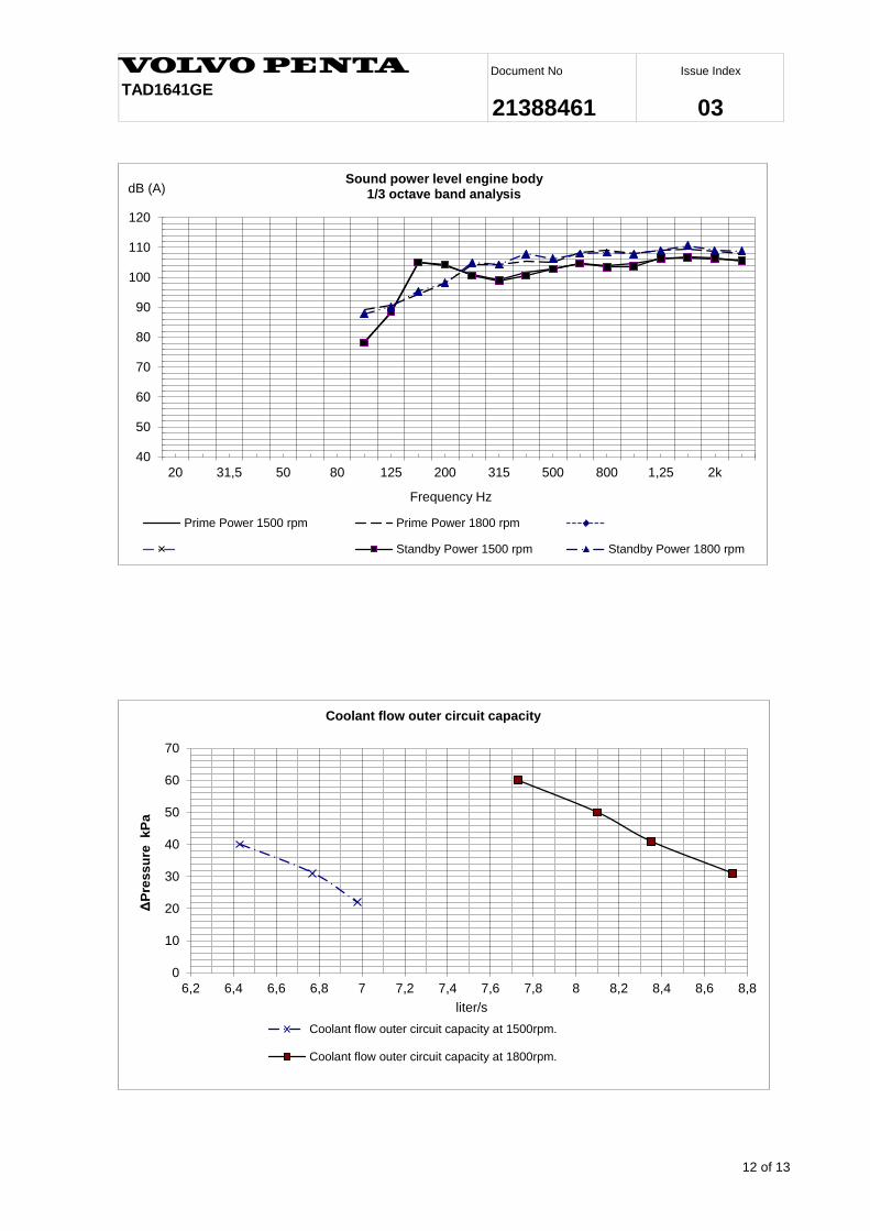
20 31,5 50 80 125 200 315 500 800 1,25 2k
dB (A)
Frequency Hz
Sound power level engine body 1/3 octave band analysis
Prime Power 1500 rpm Prime Power 1800 rpm
Standby Power 1500 rpm Standby Power 1800 rpm
0
10
20
30
40
50
60
70
6,2 6,4 6,6 6,8 7 7,2 7,4 7,6 7,8 8 8,2 8,4 8,6 8,8
ΔP
res
su
re k
Pa
liter/s
Coolant flow outer circuit capacity
Coolant flow outer circuit capacity at 1500rpm.
Coolant flow outer circuit capacity at 1800rpm.
13 of 13
Issue Index
03TAD1641GE
Document No
21388461
0,00
5,00
10,00
15,00
20,00
25,00
30,00
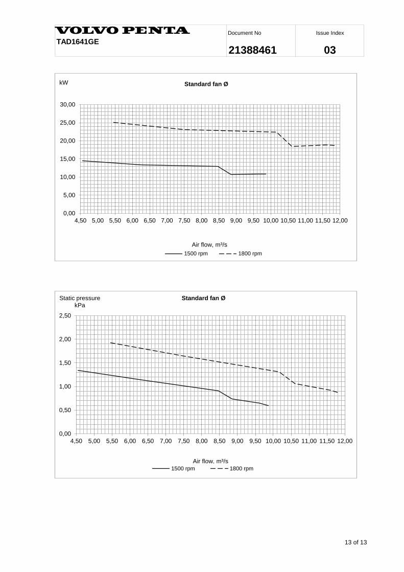
4,50 5,00 5,50 6,00 6,50 7,00 7,50 8,00 8,50 9,00 9,50 10,00 10,50 11,00 11,50 12,00
kW
Air flow, m³/s
Standard fan Ø
1500 rpm 1800 rpm
0,00
0,50
1,00
1,50
2,00
2,50
4,50 5,00 5,50 6,00 6,50 7,00 7,50 8,00 8,50 9,00 9,50 10,00 10,50 11,00 11,50 12,00
Static pressure kPa
Air flow, m³/s
Standard fan Ø
1500 rpm 1800 rpm
Industrial Generators
Blue Star Power Systems, Inc. utilizes the highest quality generators
available. Our industrial generators provide consistent performance,
quality design, and great durability required for long life and
versatility. Generators used by Blue Star Power Systems, Inc. are UL
and CSA Listed (unless specified otherwise), which guarantees that
each one meets the rigorous demands of industrial power generation
and will provide safe and effective service for the life of the generator.
Blue Star Power Systems, Inc. generators range from 20 kWe
through 2000 kWe.
Blue Star Power Systems, Inc. | 52146 Ember Road, Lake Crystal, Minnesota 56055 | Phone + 1 507 726 2508 | bluestarps.com
� Enhanced Ventilation Created by a high-efficiency fan that optimizes internal airflow patterns, maximizes heat transfer, and minimizes hot spot differentials for extended winding life.
� Fully Guarded For operator safety and generator protection. No rotating or electrically energized parts are exposed. All openings are covered by louvers or screens.
� Large Conduit Box Provides ample space for easy connections and allows load line access from all sides, top, or bottom.
� Design Specs and Agency Approvals All Blue Star Power Systems, Inc. generators are UL and CSA Listed (unless specified otherwise) and meet NEMA MG1-22, BS5000, CSA C22.2, IEC 34-1 and VDE 0530 requirements.
� Class H Insulation System Utilizes an unsaturated polyester varnish for optimal insulation life and superior moisture protection.
� Optimized Windings Provide low reactances and exceptional motor starting capability. The stator windings utilize a 2/3 pitch to minimize harmonic distortion and facilitate parallel operation.
� Permanent Magnet Generator (optional) Ensures 300% short circuit current during fault conditions and provides the regulator with input power isolated from load distortion.
� Shielded Heavy-Duty Bearing Resists contamination and gives a minimum B-10 life of 40,000 hours.
� Automatic Voltage Regulator Provides accurate 1% regulation, under-speed protection, stability adjustment to optimize transient performance, and EMI filtering to commercial standards. Fully encapsulated for rugged durability in virtually any environment.
Standard Features
DVR2000E+ Digital Voltage Regulator
Blue Star Power Systems, Inc. | 52146 Ember Road, Lake Crystal, Minnesota 56055 | Phone + 1 507 726 2508 | bluestarps.com
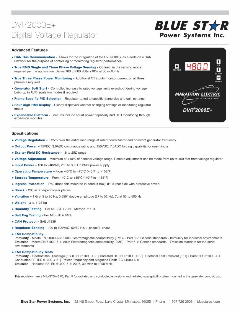
� CAN Bus Communication - Allows for the integration of the DVR2000E+ as a node on a CAN Network for the purpose of controlling or monitoring regulator performance
� True RMS Single and Three Phase Voltage Sensing - Connect in the sensing mode required per the application. Sense 100 to 600 Volts ±10% at 50 or 60 Hz
� True Three Phase Power Monitoring - Additional CT inputs monitor current on all three phases if required
� Generator Soft Start - Controlled increase to rated voltage limits overshoot during voltage build-up in AVR regulation modes if required
� Frame Specific PID Selection - Regulator tuned to specific frame size and gain settings
� Four Digit HMI Display - Clearly displayed whether changing settings or monitoring regulator status
� Expandable Platform - Features include shunt power capability and RTD monitoring through expansion modules
� Voltage Regulation – 0.25% over the entire load range at rated power factor and constant generator frequency
� Output Power – 75VDC, 3.0ADC continuous rating and 150VDC, 7.5ADC forcing capability for one minute
� Exciter Field DC Resistance – 18 to 25Ω range
� Voltage Adjustment – Minimum of ±10% of nominal voltage range. Remote adjustment can be made from up to 150 feet from voltage regulator
� Input Power – 180 to 240VAC, 250 to 300 Hz PMG power supply
� Operating Temperature – From -40°C to +70°C (-40°F to +158°F)
� Storage Temperature – From -40°C to +85°C (-40°F to +185°F)
� Ingress Protection – IP52 (front side mounted in conduit box); IP10 (rear side with protective cover)
� Shock – 20g in 3 perpendicular planes
� Vibration – 1 G at 5 to 26 Hz; 0.050” double amplitude (27 to 52 Hz); 7g at 53 to 500 Hz
� Weight – 3 lb. (1361g)
� Humidity Testing – Per MIL-STD-705B, Method 711-D
� Salt Fog Testing – Per MIL-STD- 810E
� CAN Protocol – SAE J1939
� Regulator Sensing – 100 to 600VAC, 50/60 Hz, 1-phase/3-phase
� EMI Compatibility Immunity - Meets EN 61000-6-2: 2005 Electromagnetic compatibility (EMC) – Part 6-2: Generic standards – Immunity for industrial environments Emission - Meets EN 61000-6-4: 2007 Electromagnetic compatibility (EMC) – Part 6-4: Generic standards – Emission standard for industrial environments
� EMI Compatibility Tests Immunity - Electrostatic Discharge (ESD): IEC 61000-4-2 | Radiated RF: IEC 61000-4-3 | Electrical Fast Transient (EFT) / Burst: IEC 61000-4-4 Conducted RF: IEC 61000-4-6 | Power Frequency and Magnetic Field: IEC 61000-4-8 Emission - Radiated RF: EN 61000-6-4: 2007, 30 MHz to 1000 MHz This regulator meets MIL-STD-461C, Part 9 for radiated and conducted emissions and radiated susceptibility when mounted in the generator conduit box.
Advanced Features
Specifications
DGC-2020 Gen-Set Controller
� UL Recognized, CSA & CE approved � Microprocessor based � Complete system metering
� Remote communication options � Rugged encapsulated construction
Highlights
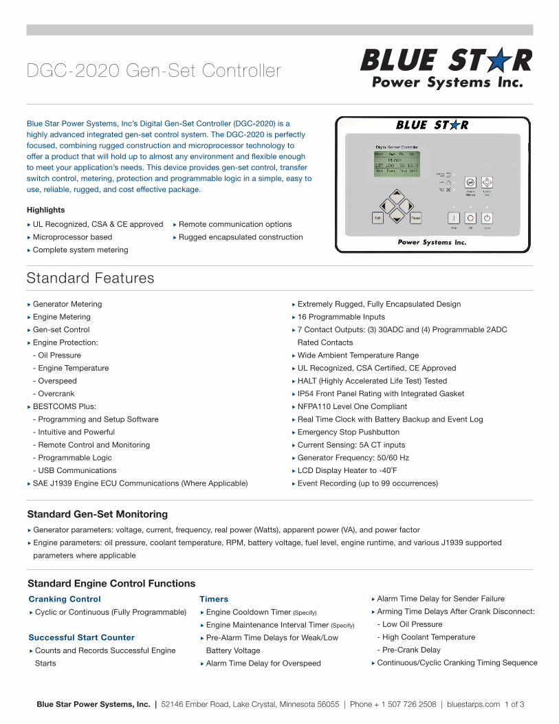
Blue Star Power Systems, Inc’s Digital Gen-Set Controller (DGC-2020) is a highly advanced integrated gen-set control system. The DGC-2020 is perfectly focused, combining rugged construction and microprocessor technology to offer a product that will hold up to almost any environment and flexible enough to meet your application’s needs. This device provides gen-set control, transfer switch control, metering, protection and programmable logic in a simple, easy to use, reliable, rugged, and cost effective package.
� Generator Metering � Engine Metering � Gen-set Control � Engine Protection: - Oil Pressure - Engine Temperature - Overspeed - Overcrank � BESTCOMS Plus: - Programming and Setup Software - Intuitive and Powerful - Remote Control and Monitoring - Programmable Logic - USB Communications � SAE J1939 Engine ECU Communications (Where Applicable)
� Extremely Rugged, Fully Encapsulated Design � 16 Programmable Inputs � 7 Contact Outputs: (3) 30ADC and (4) Programmable 2ADC Rated Contacts � Wide Ambient Temperature Range � UL Recognized, CSA Certified, CE Approved � HALT (Highly Accelerated Life Test) Tested � IP54 Front Panel Rating with Integrated Gasket � NFPA110 Level One Compliant � Real Time Clock with Battery Backup and Event Log � Emergency Stop Pushbutton � Current Sensing: 5A CT inputs � Generator Frequency: 50/60 Hz � LCD Display Heater to -40˚F � Event Recording (up to 99 occurrences)
Standard Gen-Set Monitoring � Generator parameters: voltage, current, frequency, real power (Watts), apparent power (VA), and power factor � Engine parameters: oil pressure, coolant temperature, RPM, battery voltage, fuel level, engine runtime, and various J1939 supported parameters where applicable
Standard Features
Blue Star Power Systems, Inc. | 52146 Ember Road, Lake Crystal, Minnesota 56055 | Phone + 1 507 726 2508 | bluestarps.com 1 of 3
Standard Engine Control FunctionsCranking Control
� Cyclic or Continuous (Fully Programmable)
Successful Start Counter � Counts and Records Successful Engine Starts
Timers � Engine Cooldown Timer (Specify)
� Engine Maintenance Interval Timer (Specify)
� Pre-Alarm Time Delays for Weak/Low Battery Voltage � Alarm Time Delay for Overspeed
� Alarm Time Delay for Sender Failure � Arming Time Delays After Crank Disconnect: - Low Oil Pressure - High Coolant Temperature - Pre-Crank Delay � Continuous/Cyclic Cranking Timing Sequence
DGC-2020 Gen-Set Controller
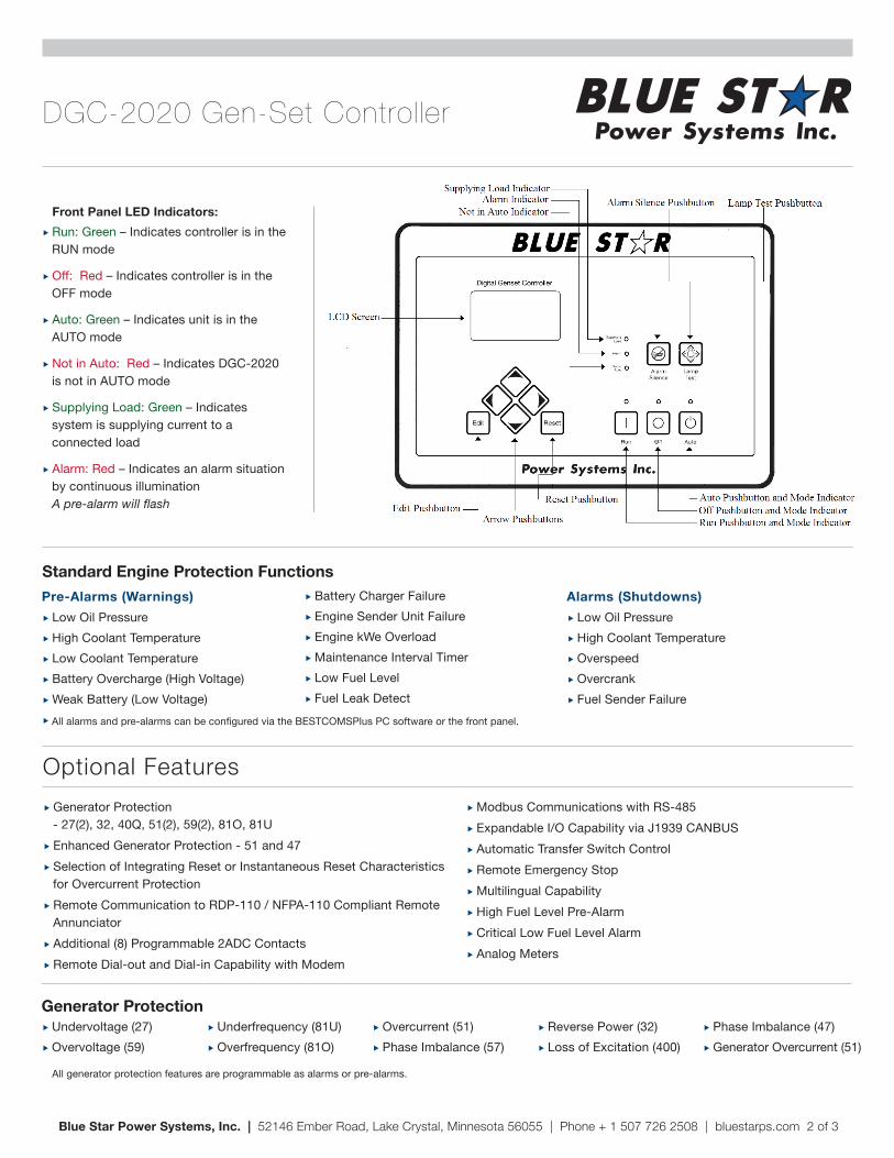
� Run: Green – Indicates controller is in the RUN mode
� Off: Red – Indicates controller is in the OFF mode
� Auto: Green – Indicates unit is in the AUTO mode
� Not in Auto: Red – Indicates DGC-2020 is not in AUTO mode
� Supplying Load: Green – Indicates system is supplying current to a connected load
� Alarm: Red – Indicates an alarm situation by continuous illumination A pre-alarm will flash
Front Panel LED Indicators:
� Generator Protection - 27(2), 32, 40Q, 51(2), 59(2), 81O, 81U � Enhanced Generator Protection - 51 and 47 � Selection of Integrating Reset or Instantaneous Reset Characteristics for Overcurrent Protection � Remote Communication to RDP-110 / NFPA-110 Compliant Remote Annunciator � Additional (8) Programmable 2ADC Contacts � Remote Dial-out and Dial-in Capability with Modem
� Modbus Communications with RS-485 � Expandable I/O Capability via J1939 CANBUS � Automatic Transfer Switch Control � Remote Emergency Stop � Multilingual Capability � High Fuel Level Pre-Alarm � Critical Low Fuel Level Alarm � Analog Meters
Optional Features
Blue Star Power Systems, Inc. | 52146 Ember Road, Lake Crystal, Minnesota 56055 | Phone + 1 507 726 2508 | bluestarps.com 2 of 3
Standard Engine Protection Functions
All alarms and pre-alarms can be configured via the BESTCOMSPlus PC software or the front panel.
Pre-Alarms (Warnings) � Low Oil Pressure � High Coolant Temperature � Low Coolant Temperature � Battery Overcharge (High Voltage) � Weak Battery (Low Voltage) �
� Battery Charger Failure � Engine Sender Unit Failure � Engine kWe Overload � Maintenance Interval Timer � Low Fuel Level � Fuel Leak Detect
Alarms (Shutdowns) � Low Oil Pressure � High Coolant Temperature � Overspeed � Overcrank � Fuel Sender Failure
Generator Protection
All generator protection features are programmable as alarms or pre-alarms.
� Undervoltage (27) � Overvoltage (59)
� Underfrequency (81U) � Overfrequency (81O)
� Overcurrent (51) � Phase Imbalance (57)
� Reverse Power (32) � Loss of Excitation (400)
� Phase Imbalance (47) � Generator Overcurrent (51)
Contact OutputsFor those applications where more output contacts are needed, the DGC-2020 can be adapted to include 8 additional 2ADC rated dry contact outputs. These are real contacts and not the solid-state type that require additional external circuitry to properly operate. These contacts are fully programmable via the easy-to-use BESTCOMSPlus PC software and can be assigned to numerous user-defined functions.
DC Voltage Panel Mounted ModemThe DGC-2020 can provide long distance communication by adding a modem. When a modem is used, the user can access the DGC-2020 from virtually anywhere via a dedicated telephone line. The user can monitor and control the gen-set as if standing right in front of it. The DGC-2020 can also dial out for pre-programmed circumstances to alert the user of selected situations.
RS-485 CommunicationWhen the RS-485 option is selected, the user can send and receive information from the DGC-2020 via the RS-485 communications port and Modbus protocol. This feature allows the DGC-2020 to be fully integrated into the building management system. Please see the instruction manual for the Modbus register list.
Enhanced Generator ProtectionIn addition to the standard generator protection (27, 59, 81O, 81U) the DGC-2020 can be equipped with a more sophisticated generator protection system. This option provides an overcurrent element (51) with 17 selectable time current characteristic curves and a voltage phase balance protection function.
Transfer Switch Control (Mains Failure)The DGC-2020 monitors utility (mains) and determines if it is providing power that is suitable for the loads. If the utility supply goes outside of predetermined levels, the generator is started and the utility is disconnected from the load and the generator is connected. When the utility returns to acceptable levels for a sufficient time, the generator is disconnected and the utility is reconnected to the load. It also includes appropriate adjustable timers or time delays for establishing stable utility operation.
Contact Expansion Module (CEM) The CEM add-on module increases the contact input and contact output capability adding 10 contact inputs and 24 form C contact outputs. This module communicates to the DGC-2020 via SAE J1939 CANBUS and allows the user to program the functionality of these inputs and outputs in the BESTCOMS programmable logic program. The user can add labels for the inputs and outputs that appear on BESTCOMS front panel, and in the programmable logic. All the functionality can be assigned to these inputs and outputs as if they were an integrated part of the DGC-2020. The CEM-2020 module has all of the environmental ratings, like the DGC-2020, including a model for UL Class1 Div2 applications (consult price list for part number). The output ratings of the form C contacts are: (12 contacts) 10A @ 30VDC and (12 contacts) 2A @ 30VDC. The 2A rated contacts are gold flash contacts for low current circuits. The CEM-2020 terminals accept a maximum wire size of 12 AWG while the chassis ground requires 12 AWG wire. The CEM-2020 provides the user with the flexibility to use the same model DGC-2020 gen-set controller for simple applications or more complicated applications that require contact functionality or duplication of contacts for remote annunciation. Flexibility is one of the benefits of the DGC-2020, and this add-on module enhances that benefit even further.
ModBus TCP/RTU (NetBiter RTU-TCP Gateway) NetBiter® RTU-TCP Gateway connects the fully enhanced DGC-2020 with Ethernet and mobile networks. The gateway acts as a transparent bridge translating DGC-2020 Modbus registers allowing control systems, such as PLCs, SCADA, etc. to communicate over Ethernet. One gateway is required per generator allowing multiple generator sets to be accessed and monitored simultaneously. Note: This option does not interface with BESTCOMSPlus software. Features include: connectivity between serial Modbus devices and the Modbus TCP; RS-232, RS-485 and RS-422 connectivity; Ethernet and mobile network connectivity; 10/100 Mbit/s Ethernet; web-based configuration; DIN rail mounting; and network and serial status indicators.
DGC-2020 Gen-Set Controller
Blue Star Power Systems, Inc. | 52146 Ember Road, Lake Crystal, Minnesota 56055 | Phone + 1 507 726 2508 | bluestarps.com 3 of 3
Load Share Module 2020 (LSM-2020)The LSM is an easy to connect and use add-on module for the DGC-2020 to allow the DGC-2020 to control the kW load sharing of multiple generator sets. The LSM-2020 is remotely mounted and communicates to the DGC-2020 via J1939 CANbus communications.
Gen-Set Enclosures
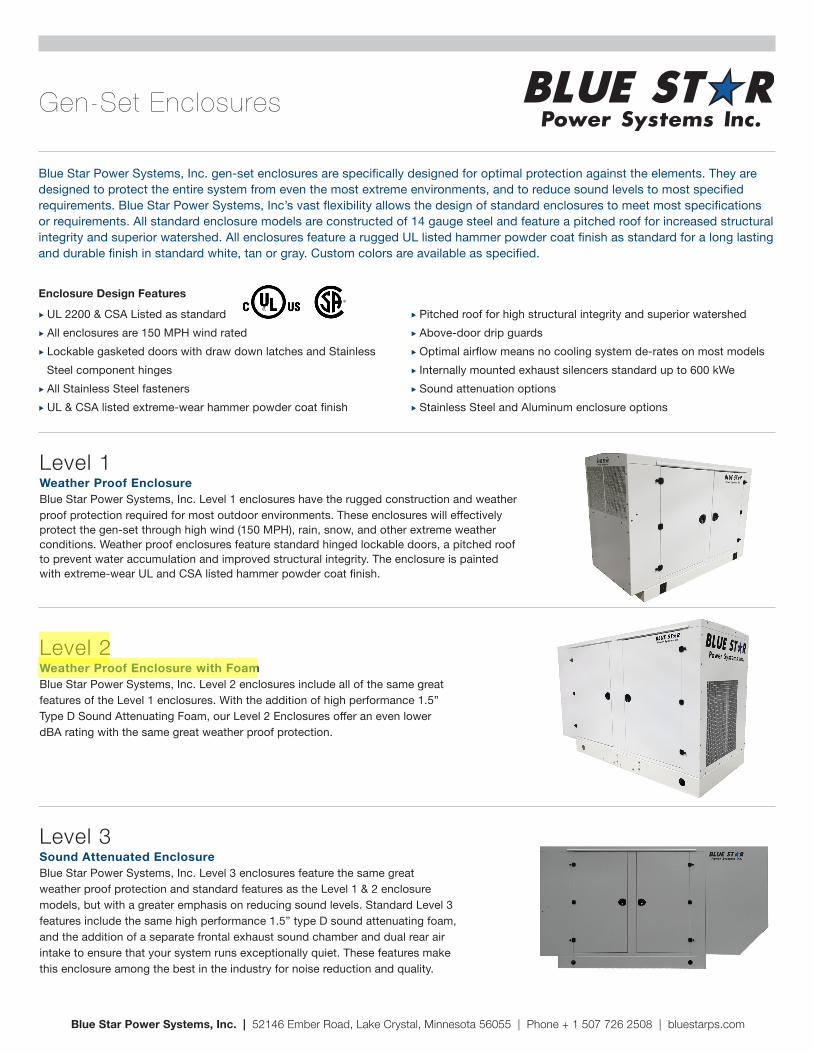
Blue Star Power Systems, Inc. gen-set enclosures are specifically designed for optimal protection against the elements. They are designed to protect the entire system from even the most extreme environments, and to reduce sound levels to most specified requirements. Blue Star Power Systems, Inc’s vast flexibility allows the design of standard enclosures to meet most specifications or requirements. All standard enclosure models are constructed of 14 gauge steel and feature a pitched roof for increased structural integrity and superior watershed. All enclosures feature a rugged UL listed hammer powder coat finish as standard for a long lasting and durable finish in standard white, tan or gray. Custom colors are available as specified.
� UL 2200 & CSA Listed as standard � All enclosures are 150 MPH wind rated � Lockable gasketed doors with draw down latches and Stainless Steel component hinges � All Stainless Steel fasteners � UL & CSA listed extreme-wear hammer powder coat finish
� Pitched roof for high structural integrity and superior watershed � Above-door drip guards � Optimal airflow means no cooling system de-rates on most models � Internally mounted exhaust silencers standard up to 600 kWe � Sound attenuation options � Stainless Steel and Aluminum enclosure options
Enclosure Design Features
Level 1Weather Proof EnclosureBlue Star Power Systems, Inc. Level 1 enclosures have the rugged construction and weather proof protection required for most outdoor environments. These enclosures will effectively protect the gen-set through high wind (150 MPH), rain, snow, and other extreme weather conditions. Weather proof enclosures feature standard hinged lockable doors, a pitched roof to prevent water accumulation and improved structural integrity. The enclosure is painted with extreme-wear UL and CSA listed hammer powder coat finish.
Level 2Weather Proof Enclosure with FoamBlue Star Power Systems, Inc. Level 2 enclosures include all of the same great features of the Level 1 enclosures. With the addition of high performance 1.5” Type D Sound Attenuating Foam, our Level 2 Enclosures offer an even lower dBA rating with the same great weather proof protection.
Level 3Sound Attenuated EnclosureBlue Star Power Systems, Inc. Level 3 enclosures feature the same great weather proof protection and standard features as the Level 1 & 2 enclosure models, but with a greater emphasis on reducing sound levels. Standard Level 3 features include the same high performance 1.5” type D sound attenuating foam, and the addition of a separate frontal exhaust sound chamber and dual rear air intake to ensure that your system runs exceptionally quiet. These features make this enclosure among the best in the industry for noise reduction and quality.
Blue Star Power Systems, Inc. | 52146 Ember Road, Lake Crystal, Minnesota 56055 | Phone + 1 507 726 2508 | bluestarps.com
Sound Attenuation Foam
Foam Characteristics
Adhesive Characteristics
Blue Star Power Systems, Inc. | 52146 Ember Road, Lake Crystal, Minnesota 56055 | Phone + 1 507 726 2508 | bluestarps.com
Test Standard U.S. Standard
Density, Nominal: (lb/ft3-kg/m3) ASTM-D-3574-91 1.85
Tensile Strength: (PSI-KPa) ASTM-D-3574-91 12
Elongation, % ASTM-D-3574-91 120
Tear Resistance: (lb/in - N/M) ASTM-D-3574-91 1.3
IFD: (PSI - KN/M2) ASTM-D-3574-91 30
Compression Set (50%): % ASTM-D-3574-91 10
Air Permeability (Tested at 1” thickness): (Rayles/M) ASTM C-522
Thermal Conductivity
(BTU/hr. ft2, ˚F/in.) ASTM C-177 0.25
Adhesive Thickness (Nominal) 0.004”
Color of Adhesive Water Clear
Release Liner 76 lb Polycoated bleached kraft paper
Service Temperature -40˚F +200˚F
Service Temperature
Continuous -45˚F (-43˚C) TO 212˚F (100˚C)
Intermittent 250˚F (121˚C)
Flame Resistance
UL94 HF-1
FAR.853(B) PASS
SAEJ-369(B) PASS
MVSS-302 PASS
DIN PASS
Humidity Resistance
Excellent; no significant decrease in tensile strength or elongation after 5 hrs. of steam autoclave at 250˚F (121˚C) per ASTM D3574-86, Test J.
Chemical Resistance
Excellent - no significant change in strength after 4 weeks immersion in common solvents, alkalies, acids, and water.
Estimated Service Life:
Min. 10 years at 80F (27˚C) and 95% R.H.
Foam Thickness 125 250 500 1000 2000 4000
(1.5 in) 38.1 mm 15/20 27/49 60/96 77/93 90/82 98/67
(2.0 in) 50.8 mm 20/30 40/66 90/98 100/96 96/85 100/75
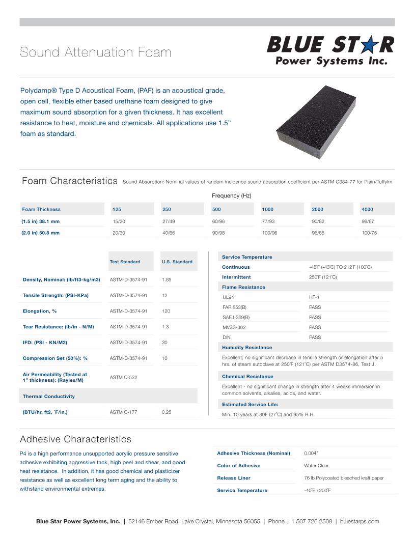
Polydamp® Type D Acoustical Foam, (PAF) is an acoustical grade, open cell, flexible ether based urethane foam designed to give maximum sound absorption for a given thickness. It has excellent resistance to heat, moisture and chemicals. All applications use 1.5” foam as standard.
P4 is a high performance unsupported acrylic pressure sensitive adhesive exhibiting aggressive tack, high peel and shear, and good heat resistance. In addition, it has good chemical and plasticizer resistance as well as excellent long term aging and the ability to withstand environmental extremes.
Frequency (Hz)
Sound Absorption: Nominal values of random incidence sound absorption coefficient per ASTM C384-77 for Plain/Tuffylm
Radiators
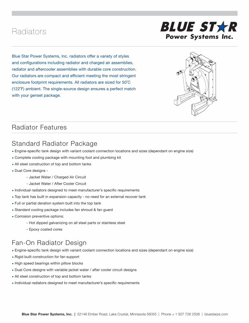
Blue Star Power Systems, Inc. radiators offer a variety of styles and configurations including radiator and charged air assemblies, radiator and aftercooler assemblies with durable core construction. Our radiators are compact and efficient meeting the most stringent enclosure footprint requirements. All radiators are sized for 50˚C (122˚F) ambient. The single-source design ensures a perfect match with your genset package.
Radiator Features
Blue Star Power Systems, Inc. | 52146 Ember Road, Lake Crystal, Minnesota 56055 | Phone + 1 507 726 2508 | bluestarps.com
Standard Radiator Package � Engine-specific tank design with variant coolant connection locations and sizes (dependant on engine size) � Complete cooling package with mounting foot and plumbing kit � All steel construction of top and bottom tanks � Dual Core designs -
- Jacket Water / Charged Air Circuit - Jacket Water / After Cooler Circuit
� Individual radiators designed to meet manufacturer’s specific requirements � Top tank has built in expansion capacity - no need for an external recover tank � Full or partial deration system built into the top tank � Standard cooling package includes fan shroud & fan guard � Corrosion preventive options: - Hot dipped galvanizing on all steel parts or stainless steel - Epoxy coated cores
Fan-On Radiator Design � Engine-specific tank design with variant coolant connection locations and sizes (dependant on engine size) � Rigid built construction for fan support � High speed bearings within pillow blocks � Dual Core designs with variable jacket water / after cooler circuit designs � All steel construction of top and bottom tanks � Individual radiators designed to meet manufacturer’s specific requirements
CB / CL Series Engine Block Heaters
� Easy Starts � Saves warm-up time � Saves fuel � Prolongs battery life � Protects the Environment � Reduces “white smoke” upon start-up � Engine is ready for full power operation � Reduces noise pollution
� Reduces Engine Wear � 90% of engine wear is due to low jacket water temp upon start-up � Stops destructive condensation � Extends engine life
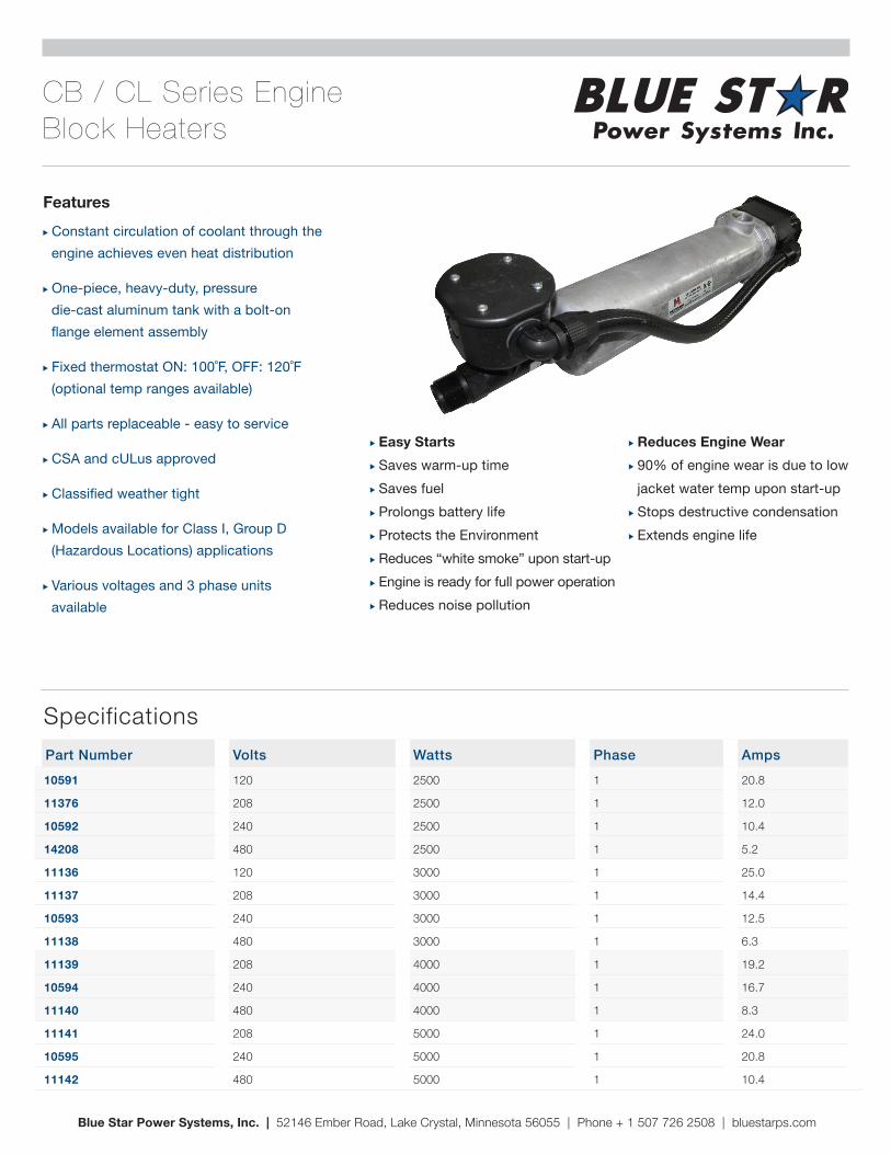
� Constant circulation of coolant through the engine achieves even heat distribution
� One-piece, heavy-duty, pressure die-cast aluminum tank with a bolt-on flange element assembly
� Fixed thermostat ON: 100˚F, OFF: 120˚F (optional temp ranges available)
� All parts replaceable - easy to service
� CSA and cULus approved
� Classified weather tight
� Models available for Class I, Group D (Hazardous Locations) applications
� Various voltages and 3 phase units available
Blue Star Power Systems, Inc. | 52146 Ember Road, Lake Crystal, Minnesota 56055 | Phone + 1 507 726 2508 | bluestarps.com
Part Number Volts Watts Phase Amps10591 120 2500 1 20.8
11376 208 2500 1 12.0
10592 240 2500 1 10.4
14208 480 2500 1 5.2
11136 120 3000 1 25.0
11137 208 3000 1 14.4
10593 240 3000 1 12.5
11138 480 3000 1 6.3
11139 208 4000 1 19.2
10594 240 4000 1 16.7
11140 480 4000 1 8.3
11141 208 5000 1 24.0
10595 240 5000 1 20.8
11142 480 5000 1 10.4
Specifications
Features
CPJ Series Crit ical Grade Silencers
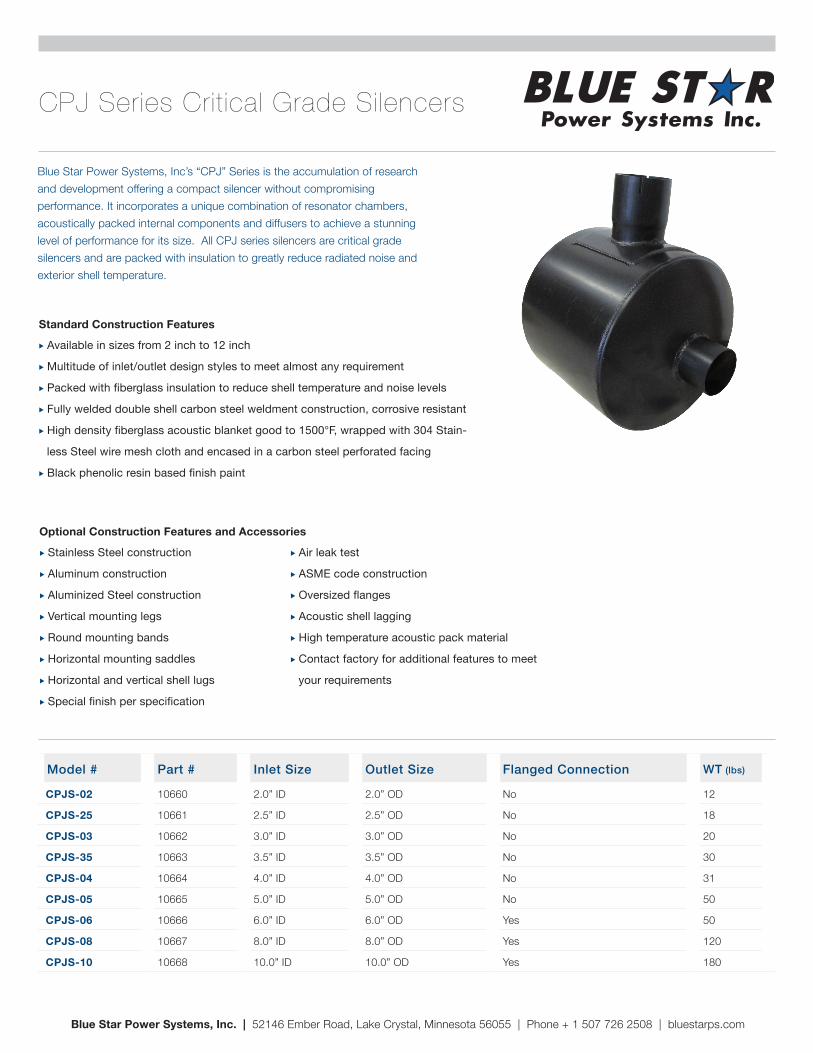
Blue Star Power Systems, Inc’s “CPJ” Series is the accumulation of research and development offering a compact silencer without compromising performance. It incorporates a unique combination of resonator chambers, acoustically packed internal components and diffusers to achieve a stunning level of performance for its size. All CPJ series silencers are critical grade silencers and are packed with insulation to greatly reduce radiated noise and exterior shell temperature.
� Available in sizes from 2 inch to 12 inch
� Multitude of inlet/outlet design styles to meet almost any requirement
� Packed with fiberglass insulation to reduce shell temperature and noise levels
� Fully welded double shell carbon steel weldment construction, corrosive resistant
� High density fiberglass acoustic blanket good to 1500°F, wrapped with 304 Stain-
less Steel wire mesh cloth and encased in a carbon steel perforated facing
� Black phenolic resin based finish paint
Standard Construction Features
� Stainless Steel construction
� Aluminum construction
� Aluminized Steel construction
� Vertical mounting legs
� Round mounting bands
� Horizontal mounting saddles
� Horizontal and vertical shell lugs
� Special finish per specification
� Air leak test
� ASME code construction
� Oversized flanges
� Acoustic shell lagging
� High temperature acoustic pack material
� Contact factory for additional features to meet
your requirements
Optional Construction Features and Accessories
Blue Star Power Systems, Inc. | 52146 Ember Road, Lake Crystal, Minnesota 56055 | Phone + 1 507 726 2508 | bluestarps.com
Model # Part # Inlet Size Outlet Size Flanged Connection WT (lbs)
CPJS-02 10660 2.0” ID 2.0” OD No 12
CPJS-25 10661 2.5” ID 2.5” OD No 18
CPJS-03 10662 3.0” ID 3.0” OD No 20
CPJS-35 10663 3.5” ID 3.5” OD No 30
CPJS-04 10664 4.0” ID 4.0” OD No 31
CPJS-05 10665 5.0” ID 5.0” OD No 50
CPJS-06 10666 6.0” ID 6.0” OD Yes 50
CPJS-08 10667 8.0” ID 8.0” OD Yes 120
CPJS-10 10668 10.0” ID 10.0” OD Yes 180
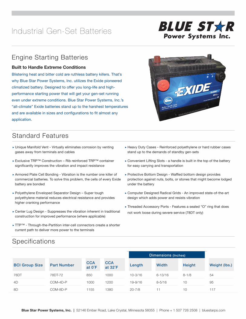
Industrial Gen-Set Batteries
Engine Starting BatteriesBuilt to Handle Extreme ConditionsBlistering heat and bitter cold are ruthless battery killers. That’s why Blue Star Power Systems, Inc. utilizes the Exide pioneered climatized battery. Designed to offer you long-life and high-performance starting power that will get your gen-set running even under extreme conditions. Blue Star Power Systems, Inc.’s “all-climate” Exide batteries stand up to the harshest temperatures and are available in sizes and configurations to fit almost any application.
Blue Star Power Systems, Inc. | 52146 Ember Road, Lake Crystal, Minnesota 56055 | Phone + 1 507 726 2508 | bluestarps.com
� Unique Manifold Vent - Virtually eliminates corrosion by venting gases away from terminals and cables
� Exclusive TRP™ Construction – Rib reinforced TRP™ container significantly improves the vibration and impact resistance
� Armored Plate Cell Bonding - Vibration is the number one killer of commercial batteries. To solve this problem, the cells of every Exide battery are bonded
� Polyethylene Enveloped Separator Design – Super tough polyethylene material reduces electrical resistance and provides higher cranking performance
� Center Lug Design - Suppresses the vibration inherent in traditional construction for improved performance (where applicable)
� TTP™ - Through-the-Partition inter-cell connectors create a shorter current path to deliver more power to the terminals
� Heavy Duty Cases - Reinforced polyethylene or hard rubber cases stand up to the demands of standby gen-sets
� Convenient Lifting Slots - a handle is built in the top of the battery for easy carrying and transportation
� Protective Bottom Design - Waffled bottom design provides protection against nuts, bolts, or stones that might become lodged under the battery
� Computer Designed Radical Grids - An improved state-of-the-art design which adds power and resists vibration
� Threaded Accessory Ports - Features a sealed “O” ring that does not work loose during severe service (78DT only)
Standard Features
Specifications
NEMA Type Dimensions (Inches)
BCI Group Size Part Number CCA at 0˚F
CCA at 32˚F Length Width Height Weight (lbs.)
78DT 78DT-72 850 1000 10-3/16 6-13/16 8-1/8 54
4D COM-4D-P 1000 1200 19-9/16 8-5/16 10 95
8D COM-8D-P 1155 1380 20-7/8 11 10 117
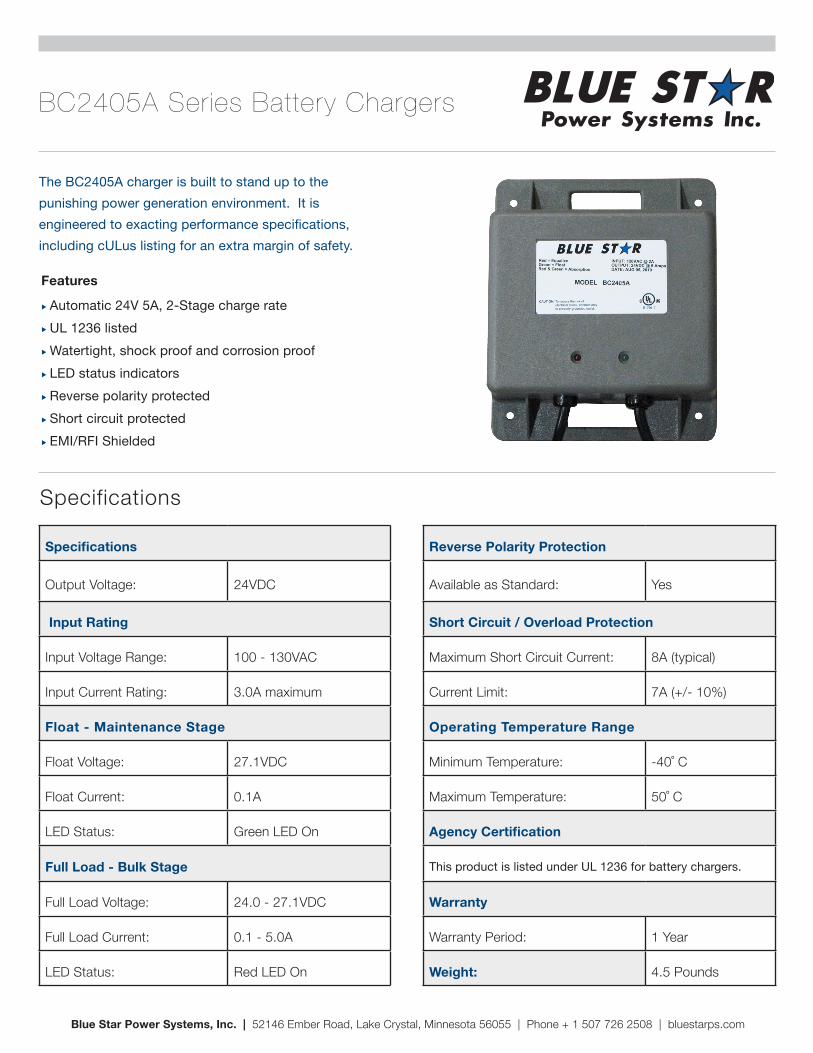
BC2405A Series Battery Chargers
� Automatic 24V 5A, 2-Stage charge rate � UL 1236 listed � Watertight, shock proof and corrosion proof � LED status indicators � Reverse polarity protected � Short circuit protected � EMI/RFI Shielded
Features
The BC2405A charger is built to stand up to the punishing power generation environment. It is engineered to exacting performance specifications, including cULus listing for an extra margin of safety.
Blue Star Power Systems, Inc. | 52146 Ember Road, Lake Crystal, Minnesota 56055 | Phone + 1 507 726 2508 | bluestarps.com
Specifications
Specifications
Output Voltage: 24VDC
Input Rating
Input Voltage Range: 100 - 130VAC
Input Current Rating: 3.0A maximum
Float - Maintenance Stage
Float Voltage: 27.1VDC
Float Current: 0.1A
LED Status: Green LED On
Full Load - Bulk Stage
Full Load Voltage: 24.0 - 27.1VDC
Full Load Current: 0.1 - 5.0A
LED Status: Red LED On
Reverse Polarity Protection
Available as Standard: Yes
Short Circuit / Overload Protection
Maximum Short Circuit Current: 8A (typical)
Current Limit: 7A (+/- 10%)
Operating Temperature Range
Minimum Temperature: -40˚ C
Maximum Temperature: 50˚ C
Agency Certification
This product is listed under UL 1236 for battery chargers.
Warranty
Warranty Period: 1 Year
Weight: 4.5 Pounds
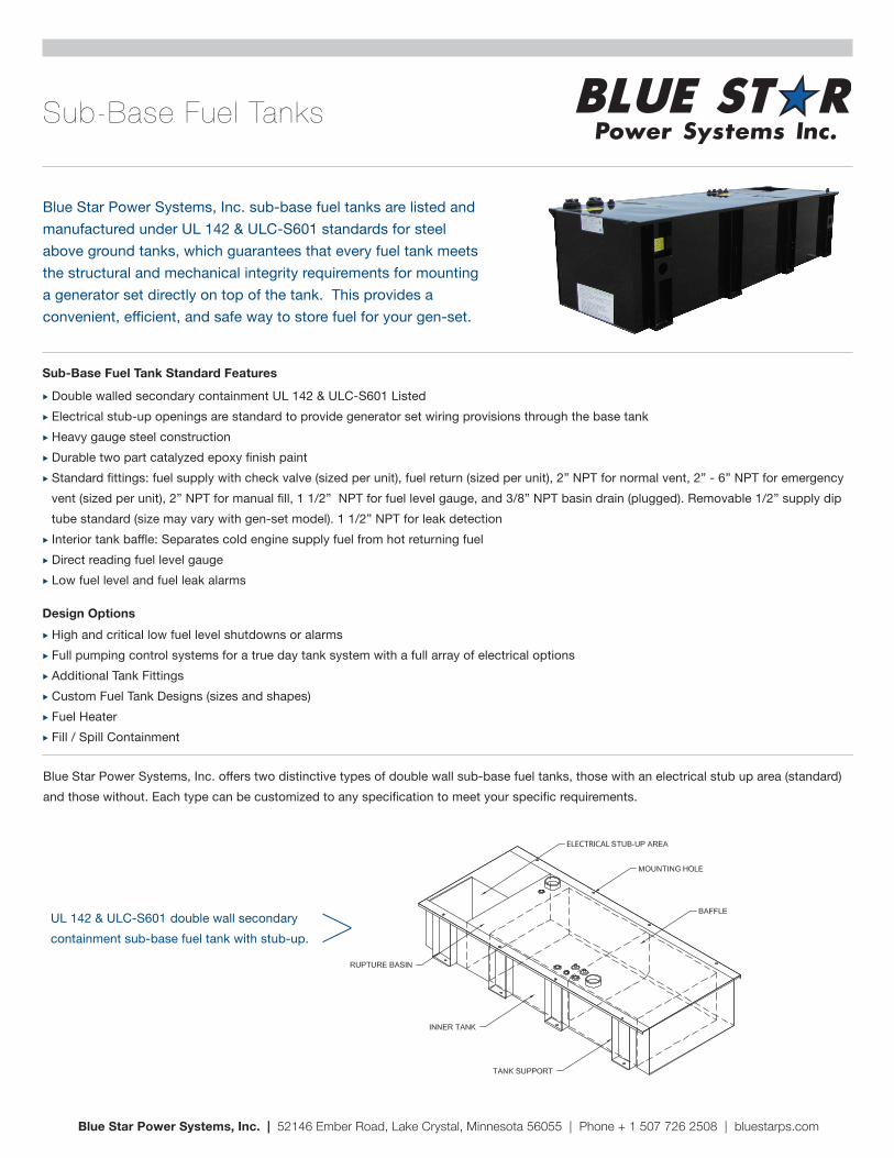
Sub-Base Fuel Tanks
Blue Star Power Systems, Inc. sub-base fuel tanks are listed and manufactured under UL 142 & ULC-S601 standards for steel above ground tanks, which guarantees that every fuel tank meets the structural and mechanical integrity requirements for mounting a generator set directly on top of the tank. This provides a convenient, efficient, and safe way to store fuel for your gen-set.
� Double walled secondary containment UL 142 & ULC-S601 Listed � Electrical stub-up openings are standard to provide generator set wiring provisions through the base tank � Heavy gauge steel construction � Durable two part catalyzed epoxy finish paint � Standard fittings: fuel supply with check valve (sized per unit), fuel return (sized per unit), 2” NPT for normal vent, 2” - 6” NPT for emergency vent (sized per unit), 2” NPT for manual fill, 1 1/2” NPT for fuel level gauge, and 3/8” NPT basin drain (plugged). Removable 1/2” supply dip tube standard (size may vary with gen-set model). 1 1/2” NPT for leak detection � Interior tank baffle: Separates cold engine supply fuel from hot returning fuel � Direct reading fuel level gauge � Low fuel level and fuel leak alarms
Sub-Base Fuel Tank Standard Features
� High and critical low fuel level shutdowns or alarms � Full pumping control systems for a true day tank system with a full array of electrical options � Additional Tank Fittings � Custom Fuel Tank Designs (sizes and shapes) � Fuel Heater � Fill / Spill Containment
Design Options
Blue Star Power Systems, Inc. | 52146 Ember Road, Lake Crystal, Minnesota 56055 | Phone + 1 507 726 2508 | bluestarps.com
ELECTRICAL
Blue Star Power Systems, Inc. offers two distinctive types of double wall sub-base fuel tanks, those with an electrical stub up area (standard) and those without. Each type can be customized to any specification to meet your specific requirements.
UL 142 & ULC-S601 double wall secondary containment sub-base fuel tank with stub-up. >
Engine Generator Set Two (2) Year 2000 Hour Standby Limited WarrantyYour Blue Star Power Systems Inc. product has been designed and manufactured with care by people with many years of experience. Blue Star Power Systems Inc. warrants to its Buyer that the product is free from defects in materials and/or workmanship for the period of time outlined below. If the product should prove defective within the time period outlined below, it will be repaired, adjusted or replaced at the option of Blue Star Power Systems Inc., provided that the product, upon inspection by Blue Star Power Systems Inc., has been properly installed, maintained and operated in accordance with Blue Star Power Systems Inc.’s Installation and Operating Manuals. This limited warranty is not valid or enforceable unless: (1) all supporting maintenance records are kept on file with the end user and made available upon request from factory, and (2) the generator set is routinely exercised in accordance with operating instructions. This warranty does not apply to malfunctions caused by physical damage, misuse, improper installation, repair or service by unauthorized persons, or normal wear and tear. The warranty is not assignable.
Blue Star Power Systems Inc. product warranty period: Engine generator set: Parts and Labor for two (2) years from the date of factory invoice or 2000 hours (whichever occurs first). Accessories (installed on the engine generator set or shipped loose): Parts and Labor for one (1) year from the date of factory invoice or 2000 hours (whichever occurs first). Transfer Switches: If purchased with a generator set (same order number): Parts and Labor for two (2) years from the date of factory invoice or 2000 hours (whichever occurs first).
The start of the warranty period can be adjusted to the date of unit start-up (limited to 180 days from invoice date) provided that the following information is provided to Blue Star Power Systems Inc. at the time of start-up. The warranty will not be effective unless a copy of the Blue Star Power Systems Inc. start-up validation checklist is properly and completely filled out and returned to Blue Star Power Systems Inc. within 30 days of start-up. Additionally, the engine manufacturer’s engine registration form must be completed and returned to the engine manufacturer as stated in the instructions with the registration form.
To obtain warranty service: Contact your nearest Blue Star Power Systems Inc. Service Representative. For assistance in locating your nearest authorized service representative, contact Blue Star Power Systems Inc., Attention: Service Department (see contact information below).
Warranty service may be performed by authorized Blue Star Power Systems Inc. service providers only. Service work performed by unauthorized persons will void all warranties.
Blue Star Power Systems Inc. shall not be liable for any claim in amount greater than the purchase price of the product. In no event shall Blue Star Power Systems Inc. be held liable for any special, indirect, consequential or liquidated damages.
Blue Star Power Systems Inc. shall not be liable for any claim that requires replacement of engine, part, or component of the gen-set that is no longer manufactured or available. Additionally, Blue Star Power Systems Inc. will not be liable for any engine replacement that may require emissions tier level change.
THERE ARE NO EXPRESS WARRANTIES OTHER THAN THOSE DESCRIBED HEREIN. THERE ARE NO OTHER WARRANTIES, EXPRESSED OR IMPLIED, OR OTHERWISE CREATED UNDER THE UNIFORM COMMERCIAL CODE, INCLUDING BUT NOT LIMITED TO WARRANTIES OF MERCHANTABILITY, OR WARRANTIES OF FITNESS FOR A PARTICULAR PURPOSE.
The following items and/or circumstances are excluded from this limited warranty: � Engine starting batteries: The battery manufacturers’ warranty applies. Consult your local battery supplier for warranty service. � Fuel system and/or governing system adjustments performed during or after start-up. � Normal maintenance items: Consumable items such as belts, filters and hoses. � Adjustments and tune–ups performed during start-up or thereafter. � Loose connections (electrical and mechanical) not found during start-up. � All fluid level related items including low coolant not found during start-up or checked during regular maintenance intervals. � Equipment modifications made without the written consent of Blue Star Power Systems Inc. will void all warranties. � Shipping damage of any type. All equipment is shipped F.O.B. factory and risk of loss transfers to the carrier once loaded for shipment. It is the responsibility of the receiving party to sign for the receipt of, and note any shipping damage to the equipment. Freight damage claim filing is the responsibility of the receiving party. In the rare event that damage occurs during shipment, Blue Star Power Systems Inc. will not warrant any damage to the unit resulting from shrink wrap. � Any special access fees, requirements or after hours scheduling to gain access to the equipment for warranty service purposes. � Buyer requested rental generators used while warranty work is being performed. � Damages caused by acts of nature, such as lightning, wind, flood, or earthquake. � Any damage due to situations beyond the control of the manufacturing and/or workmanship of the product. � Use of non-protected steel enclosure within 10 miles of the coast. � Improper installation or operation as outlined in the Installation and Operation Manuals. � Misapplication of the equipment such as usage outside the original design parameters as stated on the nameplate of the equipment. � Equipment purchased at the standby rating that is being used in a prime power application(s). � Diesel engine “Wet Stacking” due to lightly loaded diesel engines. � All travel labor and mileage on portable equipment must be approved before any work is performed.
Terms of warranty shall be deemed made and executed in Lake Crystal, Blue Earth County, Minnesota. Venue for all legal proceedings shall be in Blue Earth County, Minnesota.
Blue Star Power Systems Inc. | 52146 Ember Road, Lake Crystal, Minnesota 56055 | Phone + 1 507 726 2508 | bluestarps.com | Revised 01/05/16