Embed Size (px)
Citation preview
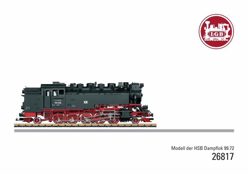
Modell der HSB Dampflok 99.72
26817

2
3
Inhaltsverzeichnis: SeiteSicherheitshinweise 4Wichtige Hinweise 4Funktionen 4Betriebshinweise 4Multiprotokollbetrieb 5Wartung und Instandhaltung 6Schaltbare Funktionen 6CV -Tabelle 7Bilder 28Ersatzteile 30
Table of Contents: Page Safety Notes 8Important Notes 8Functions 8Information about operation 8Multi-Protocol Operation 9Service and maintenance 10Controllable Functions 10Table for CV 11Figures 28Spare parts 30
Inhoudsopgave: PaginaVeiligheidsvoorschriften 16Belangrijke aanwijzing 16Functies 16Bedrijfsaanwijzingen 16Multiprotocolbedrijf 17Onderhoud en handhaving 18Schakelbare functies 18CV 19Afbeeldingen 28Onderdelen 30
Indice del contenuto: PaginaAvvertenze per la sicurezza 24Avvertenze importanti 24Funzioni 24Avvertenze per ilfunzionamento 24Esercizio multi-protocollo 25Manutenzione ed assistere 26Funzioni commutabili 26CV 27Figures 28Pezzi di ricambio 30
Sommaire : PageRemarques importantes sur la sécurité 12Information importante 12Fonctionnement 12Remarques sur l’exploitation 12Mode multiprotocole 13Entretien et maintien 14Fonctions commutables 14CV 15Images 28Pièces de rechange 30
Indice de contenido: PáginaAviso de seguridad 20Notas importantes 20Funciones 20Instrucciones de uso 20Funcionamiento multiprotocolo 21El mantenimiento 22Funciones commutables 22CV 23Figuras 28Recambios 30
4
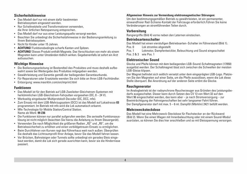
Sicherheitshinweise • Das Modell darf nur mit einem dafür bestimmten
Betriebssystem eingesetzt werden. • Nur Schaltnetzteile und Transformatoren verwenden,
die Ihrer örtlichen Netzspannung entsprechen.• Das Modell darf nur aus einer Leistungsquelle versorgt werden. • Beachten Sie unbedingt die Sicherheitshinweise in der Bedienungsanleitung zu
Ihrem Betriebssystem. • Nicht für Kinder unter 15 Jahren. • ACHTUNG! Funktionsbedingte scharfe Kanten und Spitzen. • ACHTUNG! Dieses Produkt enthält Magnete. Das Verschlucken von mehr als einem
Magneten kann unter Umständen tödlich wirken. Gegebenenfalls ist sofort ein Arzt aufzusuchen.
Wichtige Hinweise • Die Bedienungsanleitung ist Bestandteil des Produktes und muss deshalb aufbe-
wahrt sowie bei Weitergabe des Produktes mitgegeben werden. • Gewährleistung und Garantie gemäß der beiliegenden Garantieurkunde.• Für Reparaturen oder Ersatzteile wenden Sie sich bitte an Ihren LGB-Fachhändler. • Entsorgung: www.maerklin.com/en/imprint.html
Funktionen• Das Modell ist für den Betrieb auf LGB-Zweileiter-Gleichstrom-Systemen mit
herkömmlichen LGB-Gleichstrom-Fahrpulten vorgesehen (DC, 0 – 24 V). • Werkseitig eingebauter Multiprotokoll-Decoder (DC, DCC, mfx). • Zum Einsatz mit dem LGB-Mehrzugsystem (DCC) ist das Modell auf Lokadresse 03
programmiert. Im Betrieb mit mfx wird die Lok automatisch erkannt. • Mfx-Technologie für Mobile Station/Central Station.
Name ab Werk: 99 236• Die Funktionen können nur parallel aufgerufen werden. Die seriealle Funktionsaus-
lösung ist nicht möglich (beachten Sie hierzu die Anleitung zu Ihrem Steuergerät). • Verwenden Sie nach Möglichkeit die größeren Radien „R3” und „R5“, um die
Betriebssicherheit zu erhöhen und einen vorbildgetreuen Einsatz zu ermöglichen.• Beim Durchfahren von Kurven ragt das Führerhaus weit nach außen. Überprüfen
Sie deshalb das Lichtraumprofil Ihrer Anlage, bevor Sie das Modell fahren lassen.• Vor Brücken, Bahnsteigen oder Tunnels sollte unbedingt ein gerades Gleis einge-
baut werden, damit die Lok sich gerade ausrichten kann, bevor sie die Hindernisse passiert.
Allgemeiner Hinweis zur Vermeidung elektromagnetischer Störungen: Um den bestimmungsgemäßen Betrieb zu gewährleisten, ist ein permanenter, einwandfreier Rad-Schiene-Kontakt der Fahrzeuge erforderlich.Führen Sie keine Veränderungen an stromführenden Teilen durch.
VorbereitungRangiergriffe (Bild 4) vorne neben den Laternen einstecken.Betriebsartenschalter Das Modell hat einen vierstufigen Betriebsarten–Schalter im Führerstand (Bild 1).Pos. 0 Lok stromlos abgestelltPos. 1 Lokmotor, Dampfentwickler, Beleuchtung und Sound eingeschaltetPos. 2 & 3 wie Pos. 1
Elektronischer SoundGlocke und Pfeife können mit dem beiliegenden LGB-Sound-Schaltmagneten (17050) ausgelöst werden. Der Schaltmagnet lässt sich zwischen die Schwellen der meisten LGB-Gleise klipsen. Der Magnet befindet sich seitlich versetzt unter dem eingeprägten LGB-Logo. Platzie-ren Sie den Magneten auf einer Seite, um die Pfeife auszulösen, wenn die Lok diese Stelle überquert. Bei Anordnung auf der anderen Seite ertönt die Glocke.
RauchgeneratorIm Analogbetrieb ist der radsynchrone Raucherzeuger aus Gründen des Leistungsbe-darfs ausgeschaltet. Dieser kann durch Setzen des CV 13 von Wert 32 auf den Wert 96 eingeschaltet werden, das kann aber – je nach Stromversorgung – zur Beeinträchtigung der Fahreigenschaften bei sehr langsamer Fahrt führen.Der Dampfgenerator darf mit max. 5 – 6 ml. Dampföl (Märklin) 2421 befüllt werden.
Mehrzwecksteckdose Das Modell hat eine Mehrzweck-Steckdose für Flachstecker an der Rückwand (Bild 2). Wenn Sie einen Wagen mit Innenbeleuchtung oder mit einem Sound-Modul ausrüsten, so können Sie dies hier anschließen und so mit Gleisspannung versorgen.
5
Multiprotokollbetrieb AnalogbetriebDer Decoder kann auch auf analogen Anlagen oder Gleisabschnitten betrieben wer-den. Der Decoder erkennt die analoge Gleichspannung (DC) automatisch und passt sich der analogen Gleisspannung an. Es sind alle Funktionen, die unter mfx oder DCC für den Analogbetrieb eingestellt wurden aktiv (siehe Digitalbetrieb).Die Eingebauten Sound-Funktionen sind ab Werk im Analogbetrieb nicht aktiv.
DigitalbetriebDer Decoder ist ein Multiprotokolldecoder. Der Decoder kann unter folgenden Digital-Protokollen eingesetzt werden: mfx oder DCC. Das Digital-Protokoll mit den meisten Möglichkeiten ist das höchstwertige Digital-Protokoll. Die Reihenfolge der Digital-Protokolle ist in der Wertung fallend:Priorität 1: mfx; Priorität 2: DCC; Priorität 3: DCHinweis: Digital-Protokolle können sich gegenseitig beeinflussen. Für einen stö-rungsfreien Betrieb empfehlen wir, nicht benötigte Digital-Protokolle mit Configura-tions Variable (CV) 50 zu deaktivieren.Deaktivieren Sie, sofern dies Ihre Zentrale unterstützt, auch dort die nicht benötigten Digital-Protokolle.Werden zwei oder mehrere Digital-Protokolle am Gleis erkannt, übernimmt der De-coder automatisch das höchstwertige Digital-Protokoll, z.B. mfx/DCC, somit wird das mfx-Digital-Protokoll vom Decoder übernommen. Hinweis: Beachten Sie, dass nicht alle Funktionen in allen Digital-Protokollen möglich sind. Unter mfx und DCC können einige Einstellungen von Funktionen, welche im Analog-Betrieb wirksam sein sollen, vorgenommen werden.
Hinweise zum Digitalbetrieb • Die genaue Vorgehensweise zum Einstellen der diversen CVs entnehmen Sie bitte
der Bedienungsanleitung Ihrer Mehrzug-Zentrale.• Die ab Werk eingestellten Werte sind für mfx gewählt, so dass ein bestmöglichstes
Fahrverhalten gewährleistet ist. Für andere Betriebssysteme müssen gegebenenfalls Anpassungen getätigt werden.
mfx-ProtokollAdressierung • Keine Adresse erforderlich, jeder Decoder erhält eine einmalige und eindeutige
Kennung (UID).• Der Decoder meldet sich an einer Central Station oder Mobile Station mit seiner
UID-Kennung automatisch an.
Programmierung• Die Eigenschaften können über die grafische Oberfläche der Central Station bzw.
teilweise auch mit der Mobile Station programmiert werden. • Es können alle CV mehrfach gelesen und programmiert werden.• Die Programmierung kann entweder auf dem Haupt- oder dem Programmiergleis
erfolgen. • Die Defaulteinstellungen (Werkseinstellungen) können wieder hergestellt werden.• Funktionsmapping: Funktionen können mit Hilfe der Central Station 60212 (einge-
schränkt) und mit der Central Station 60213/60214/60215 beliebigen Funktionstasten zugeordnet werden (Siehe Hilfe in der Central Station).
DCC-ProtokollAdressierung• Kurze Adresse – Lange Adresse – Traktionsadresse• Adressbereich:
1 – 127 kurze Adresse, Traktionsadresse 1 – 10239 lange Adresse• Jede Adresse ist manuell programmierbar.• Kurze oder lange Adresse wird über die CV 29 ausgewählt.• Eine angewandte Traktionsadresse deaktiviert die Standard-Adresse.
Programmierung• Die Eigenschaften können über die Configuration Variablen (CV) mehrfach geän-
dert werden. • Die CV-Nummer und die CV-Werte werden direkt eingegeben.• Die CVs können mehrfach gelesen und programmiert werden (Programmierung
auf dem Programmiergleis).• Die CVs können beliebig programmiert werden (PoM - Programmierung auf dem
Hauptgleis). PoM ist nicht möglich bei den CV 1, 17, 18 und 29. PoM muss von Ihrer Zentrale unterstützt werden (siehe Bedienungsanleitung ihres Gerätes).
• Die Defaulteinstellungen (Werkseinstellungen) können wieder hergestellt werden.• 14 bzw. 28/128 Fahrstufen einstellbar.• Alle Funktionen können entsprechend dem Funktionsmapping geschaltet werden.• Weitere Information, siehe CV-Tabelle DCC-Protokoll. Es wird empfohlen, die Programmierungen grundsätzlich auf dem Programmiergleis vorzunehmen.
6
WARTUNG
Schmierung Die Achslager und die Lager des Gestänges hin und wieder mit je einem Tropfen Märklin-Öl (7149) ölen.
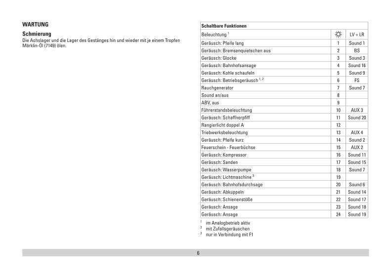
Schaltbare Funktionen
Beleuchtung 1 LV + LR
Geräusch: Pfeife lang 1 Sound 1Geräusch: Bremsenquietschen aus 2 BSGeräusch: Glocke 3 Sound 3Geräusch: Bahnhofsansage 4 Sound 16Geräusch: Kohle schaufeln 5 Sound 9Geräusch: Betriebsgeräusch 1, 2 6 FSRauchgenerator 7 Sound 7Sound an/aus 8ABV, aus 9Führerstandsbeleuchtung 10 AUX 3Geräusch: Schaffnerpfiff 11 Sound 20Rangierlicht doppel A 12Triebwerksbeleuchtung 13 AUX 4Geräusch: Pfeife kurz 14 Sound 2Feuerschein - Feuerbüchse 15 AUX 2Geräusch: Kompressor 16 Sound 11Geräusch: Sanden 17 Sound 15Geräusch: Wasserpumpe 18 Sound 7Geräusch: Lichtmaschine 3 19Geräusch: Bahnhofsdurchsage 20 Sound 6Geräusch: Abkuppeln 21 Sound 14Geräusch: Schienenstöße 22 Sound 17Geräusch: Ansage 23 Sound 18Geräusch: Ansage 24 Sound 19
1 im Analogbetrieb aktiv2 mit Zufallsgeräuschen3 nur in Verbindung mit F1
7
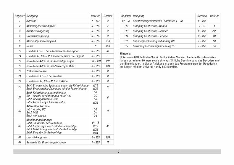
Register Belegung Bereich Default
1 Adresse 1 – 127 3
2 Minimalgeschwindigkeit 0 – 255 7
3 Anfahrverzögerung 0 – 255 3
4 Bremsverzögerung 0 – 255 3
5 Maximalgeschwindigkeit 0 – 255 213
8 Reset 8 159
13 Funktion F1 – F8 bei alternativem Gleissignal 0 – 255 32
14 Funktion FL, F9 – F15 bei alternativem Gleissignal 0 – 255 1
17 erweiterte Adresse, höherwertiges Byte 192 – 231 192
18 erweiterte Adresse, niederwertiges Byte 0 – 255 128
19 Traktionsadresse 0 – 255 0
21 Funktionen F1 – F8 bei Traktion 0 – 255 0
22 Funktionen FL, F9 – F15 bei Traktion 0 – 255 0
27 Bit 4: Bremsmodus Spannung gegen die Fahrtrichtung Bit 5: Bremsmodus Spannung mit der Fahrtrichtung
0/16 0/32 16
29
Bit 0: Fahrtrichtung normal/invers Bit 1: Anzahl der Fahrstufen 14/28(128) Bit 2: Analogbetrieb aus/an Bit 5: kurze / lange Adresse aktiv
0/10/20/40/32
6
50
Alternative Formate Bit 1: Analog DC Bit 2: MM Bit 3: mfx aus/an
0/2 0/4 0/8
15
60
Multibahnhofsansage Bit 0 – 3: Anzahl der Bahnhöfe Bit 4: Endansage wechselt die Reihenfolge Bit 5: Lokrichtung wechselt die Reihenfolge Bit 6: Vorgabe für Reihenfolge
0 – 150/160/320/64
40
63 Lautstärke gesamt 0 – 255 255
64 Schwelle für Bremsenquietschen 0 – 255 15
Register Belegung Bereich Default
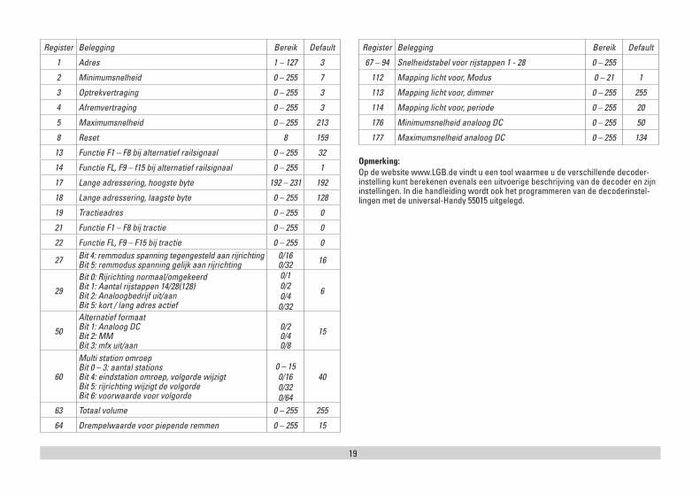
67 – 94 Geschwindigkeitstabelle Fahrstufen 1 – 28 0 – 255
112 Mapping Licht vorne, Modus 0 – 21 1
113 Mapping Licht vorne, Dimmer 0 – 255 255
114 Mapping Licht vorne, Periode 0 – 255 20
176 Minimalgeschwindigkeit analog DC 1 – 255 50
177 Maximalgeschwindigkeit analog DC 1 – 255 134
Hinweis: Unter www.LGB.de finden Sie ein Tool, mit dem Sie verschiedene Decodereinstel-lungen berechnen können, sowie eine ausführliche Beschreibung des Decoders und der Einstellungen. In dieser Anleitung ist auch das Programmieren der Decoderein-stellungen mit dem Univeral-Handy-55015 erklärt.
8
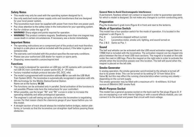
Safety Notes• This model may only be used with the operating system designed for it. • Use only switched mode power supply units and transformers that are designed
for your local power system. • This locomotive must never be supplied with power from more than one power pack. • Pay close attention to the safety notes in the instructions for your operating system. • Not for children under the age of 15. • WARNING! Sharp edges and points required for operation. • WARNING! This product contains magnets. Swallowing more than one magnet may
cause death in certain circumstances. If necessary, see a doctor immediately.
Important Notes• The operating instructions are a component part of the product and must therefore
be kept in a safe place as well as included with the product, if the latter is given to someone else.
• The warranty card included with this product specifies the warranty conditions.• Please see your authorized LGB dealer for repairs or spare parts.• Disposing: www.maerklin.com/en/imprint.html
Functions • This model is designed for operation on LGB two-rail DC systems with conventio-
nal LGB DC train controllers or power packs (DC, 0 – 24 volts). • Factory-installed multiple protocol decoder (DC, DCC, mfx).• The model is programmed with locomotive address 03 for use with the LGB Multi
Train System (DCC). The locomotive is automatically recognized in operation with mfx. • Mfx technology for the Mobile Station/Central Station.
Name set at the factory: 99 236• The functions can be activated only in parallel. Serial activation of the functions is
not possible (Please note here the instructions for your controller). • When possible, use the larger “R3“ and “R5“ curves in order to increase the
operating reliability and allow prototypical operation. • The engineer‘s cab will swing out quite a bit when the locomotive is negotiating
curves. For that reason check the clearance gauge of your layout before you run this model.
• A straight section of track should always be installed before bridges, station plat-forms, or tunnels so that the locomotive can straighten itself before passing these obstacles.
General Note to Avoid Electromagnetic Interference: A permanent, flawless wheel-rail contact is required in order to guarantee operation for which a model is designed. Do not make any changes to current-conducting parts.
PreparationPlug the brakeman‘s grab irons (Figure 4) in front and next to the lanterns.Mode of Operation SwitchThis model has a four-position switch for the mode of operation. It is located in the engineer‘s cab (Figure 1).Pos. 0 Locomotive stopped without currentPos. 1 Locomotive motor, smoke unit, lighting, and sound turned onPos. 2 & 3 Same as Pos. 1
SoundThe bell and whistle can be activated with the LGB sound activation magnet (item no. 17050) that is included with the locomotive. The activation magnet can be clipped into place between the ties of most LGB track sections. The magnet is located on the side under the cast-in LGB logo. Place the magnet on the right side in order to activate the whistle when the locomotive passes over this location. The bell will sound when the magnet is placed on the left side.
Smoke GeneratorIn analog operation, the smoke generator synchronized to the wheels is turned off due to its power draw. This can be turned on by setting CV 13 from Value 32 to Value 96, but this may affect the running characteristics when running very slowly – depending on the current supply. The smoke generator may be filled with a maximum of 5 – 6 milliliters / 0.2 fluid ounces of (Märklin) 2421 smoke fluid.
Multi-Purpose SocketThis model has a general-purpose socket on the back wall for flat plugs (Figure 2). If you are equipping a car with interior lighting or with a sound effects module, you can connect it to the socket and power that circuit with track voltage.
9
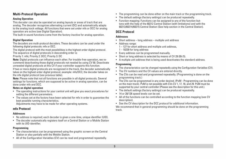
Multi-Protocol Operation Analog OperationThis decoder can also be operated on analog layouts or areas of track that are analog. The decoder recognizes alternating current (DC) and automatically adapts to the analog track voltage. All functions that were set under mfx or DCC for analog operation are active (see Digital Operation).The built-in sound functions come from the factory inactive for analog operation.
Digital OperationThe decoders are multi-protocol decoders. These decoders can be used under the following digital protocols: mfx or DCC.The digital protocol with the most possibilities is the highest order digital protocol. The sequence of digital protocols in descending order is:Priority 1: mfx; Priority 2: DCC; Priority 3: DCNote: Digital protocols can influence each other. For trouble-free operation, we re-commend deactivating those digital protocols not needed by using CV 50. Deactivate unneeded digital protocols at this CV if your controller supports this function. If two or more digital protocols are recognized in the track, the decoder automatically takes on the highest order digital protocol, example: mfx/DCC; the decoder takes on the mfx digital protocol (see previous table).Note: Please note that not all functions are possible in all digital protocols. Several settings for functions, which are supposed to be active in analog operation, can be done under mfx and DCC. Notes on digital operation • The operating instructions for your central unit will give you exact procedures for
setting the different parameters. • The values set at the factory have been selected for mfx in order to guarantee the
best possible running characteristics. Adjustments may have to be made for other operating systems.
mfx ProtocolAddresses • No address is required; each decoder is given a one-time, unique identifier (UID).• The decoder automatically registers itself on a Central Station or a Mobile Station
with its UID-identifier.
Programming • The characteristics can be programmed using the graphic screen on the Central
Station or also partially with the Mobile Station.• All of the Configuration Variables (CV) can be read and programmed repeatedly.
• The programming can be done either on the main track or the programming track.• The default settings (factory settings) can be produced repeatedly.• Function mapping: Functions can be assigned to any of the function but-
tons with the help of the 60212 Central Station (with limitations) and with the 60213/60214/60215 Central Station (See help section in the Central Station).
DCC ProtocolAddresses • Short address – long address – multiple unit address• Address range:
1 – 127 for short address and multiple unit address, 1 – 10239 for long address
• Every address can be programmed manually.• Short or long address is selected by means of CV 29 (Bit 5).• A multiple unit address that is being used deactivates the standard address.
Programming • The characteristics can be changed repeatedly using the Configuration Variables (CV).• The CV numbers and the CV values are entered directly.• The CVs can be read and programmed repeatedly. (Programming is done on the
programming track.)• The CVs can be programmed in any order desired. (PoM - Programming can be done
on the main track). PoM is not possible with CVs CV 1, 17, 18, and 29. PoM must be supported by your central controller (Please see the description for this unit.).
• The default settings (factory settings) can be produced repeatedly.• 14 or 28/126 speed levels can be set.• All of the functions can be controlled according to the function mapping (see CV
description).• See the CV description for the DCC protocol for additional information.We recommend that in general programming should be done on the programming track.
10
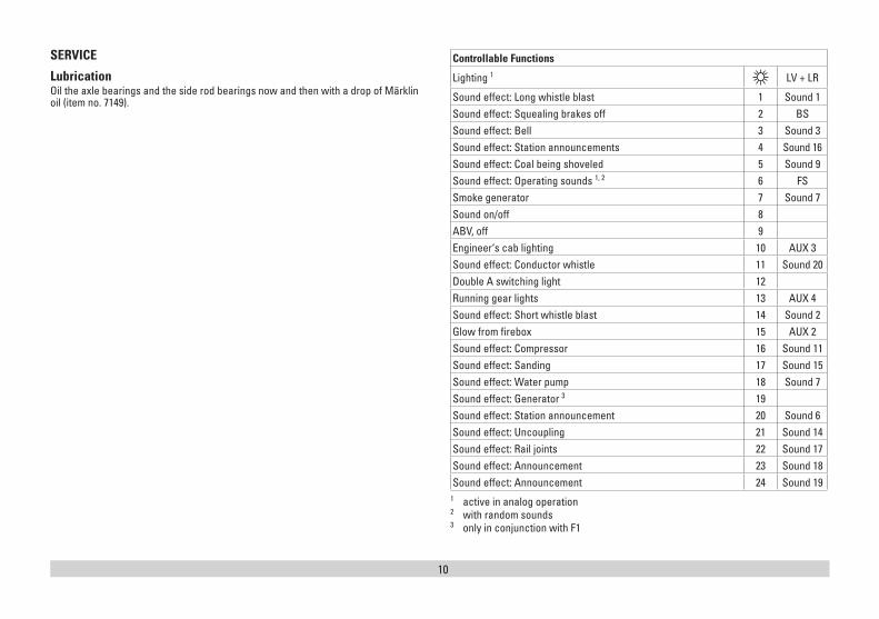
SERVICE
Lubrication Oil the axle bearings and the side rod bearings now and then with a drop of Märklin oil (item no. 7149).
Controllable Functions
Lighting 1 LV + LR
Sound effect: Long whistle blast 1 Sound 1Sound effect: Squealing brakes off 2 BSSound effect: Bell 3 Sound 3Sound effect: Station announcements 4 Sound 16Sound effect: Coal being shoveled 5 Sound 9Sound effect: Operating sounds 1, 2 6 FSSmoke generator 7 Sound 7Sound on/off 8ABV, off 9Engineer‘s cab lighting 10 AUX 3Sound effect: Conductor whistle 11 Sound 20Double A switching light 12Running gear lights 13 AUX 4Sound effect: Short whistle blast 14 Sound 2Glow from firebox 15 AUX 2Sound effect: Compressor 16 Sound 11Sound effect: Sanding 17 Sound 15Sound effect: Water pump 18 Sound 7Sound effect: Generator 3 19Sound effect: Station announcement 20 Sound 6Sound effect: Uncoupling 21 Sound 14Sound effect: Rail joints 22 Sound 17Sound effect: Announcement 23 Sound 18Sound effect: Announcement 24 Sound 19
1 active in analog operation 2 with random sounds3 only in conjunction with F1
11
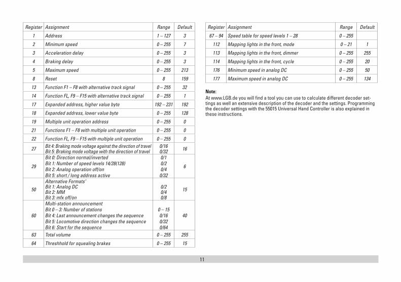
Register Assignment Range Default
1 Address 1 – 127 3
2 Minimum speed 0 – 255 7
3 Acceleration delay 0 – 255 3
4 Braking delay 0 – 255 3
5 Maximum speed 0 – 255 213
8 Reset 8 159
13 Function F1 – F8 with alternative track signal 0 – 255 32
14 Function FL, F9 – F15 with alternative track signal 0 – 255 1
17 Expanded address, higher value byte 192 – 231 192
18 Expanded address, lower value byte 0 – 255 128
19 Multiple unit operation address 0 – 255 0
21 Functions F1 – F8 with multiple unit operation 0 – 255 0
22 Function FL, F9 – F15 with multiple unit operation 0 – 255 0
27 Bit 4: Braking mode voltage against the direction of travel Bit 5: Braking mode voltage with the direction of travel
0/16 0/32 16
29
Bit 0: Direction normal/invertedBit 1: Number of speed levels 14/28(128)Bit 2: Analog operation off/onBit 5: short / long address active
0/10/20/40/32
6
50
Alternative Formats‘ Bit 1: Analog DC Bit 2: MM Bit 3: mfx off/on
0/2 0/4 0/8
15
60
Multi-station announcementBit 0 – 3: Number of stations Bit 4: Last announcement changes the sequence Bit 5: Locomotive direction changes the sequence Bit 6: Start for the sequence
0 – 150/160/320/64
40
63 Total volume 0 – 255 255
64 Threshhold for squealing brakes 0 – 255 15
Register Assignment Range Default
67 – 94 Speed table for speed levels 1 – 28 0 – 255
112 Mapping lights in the front, mode 0 – 21 1
113 Mapping lights in the front, dimmer 0 – 255 255
114 Mapping lights in the front, cycle 0 – 255 20
176 Minimum speed in analog DC 0 – 255 50
177 Maximum speed in analog DC 0 – 255 134
Note:At www.LGB.de you will find a tool you can use to calculate different decoder set-tings as well an extensive description of the decoder and the settings. Programming the decoder settings with the 55015 Universal Hand Controller is also explained in these instructions.
12
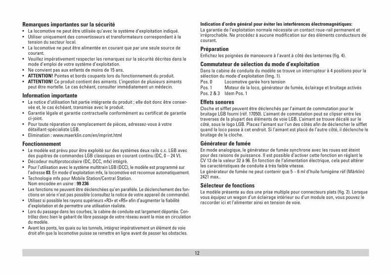
Remarques importantes sur la sécurité• La locomotive ne peut être utilisée qu‘avec le système d‘exploitation indiqué. • Utiliser uniquement des convertisseurs et transformateurs correspondant à la
tension du secteur local.• La locomotive ne peut être alimentée en courant que par une seule source de
courant. • Veuillez impérativement respecter les remarques sur la sécurité décrites dans le
mode d’emploi de votre système d’exploitation. • Ne convient pas aux enfants de moins de 15 ans. • ATTENTION! Pointes et bords coupants lors du fonctionnement du produit. • ATTENTION! Ce produit contient des aimants. L’ingestion de plusieurs aimants
peut être mortelle. Le cas échéant, consulter immédiatement un médecin.
Information importante• La notice d‘utilisation fait partie intégrante du produit ; elle doit donc être conser-
vée et, le cas échéant, transmise avec le produit. • Garantie légale et garantie contractuelle conformément au certificat de garantie
ci-joint.• Pour toute réparation ou remplacement de pièces, adressez-vous à votre
détaillant-spécialiste LGB. • Elimination : www.maerklin.com/en/imprint.html
Fonctionnement• Le modèle est prévu pour être exploité sur des systèmes deux rails c.c. LGB avec
des pupitres de commandes LGB classiques en courant continu (DC, 0 – 24 V). • Décodeur multiprotocolaire (DC, DCC, mfx) intégré.• Pour l’utilisation avec le système multitrain LGB (DCC), le modèle est programmé sur
l’adresse 03. En mode d’exploitation mfx, la locomotive est reconnue automatiquement.• Technologie mfx pour Mobile Station/Central Station.
Nom encodée en usine : 99 236• Les fonctions ne peuvent être déclenchées qu’en parallèle. Le déclenchement des fon-
ctions en série n’est pas possible (consultez la notice de votre appareil de commande).• Utilisez si possible les rayons supérieurs «R3» et «R5» afin d’augmenter la fiabilité
d’exploitation et de permettre une utilisation réaliste. • Lors du passage dans les courbes, la cabine de conduite est largement déportée. Con-
trôlez donc bien le gabarit de libre passage de votre réseau avant la mise en circulation du modèle.
• Avant les ponts, les quais ou les tunnels, intégrez impérativement un élément de voie droit afin que la locomotive puisse se remettre en ligne avant de passer les obstacles.
Indication d‘ordre général pour éviter les interférences électromagnétiques: La garantie de l‘exploitation normale nécessite un contact roue-rail permanent et irréprochable. Ne procédez à aucune modification sur des éléments conducteurs de courant.
PréparationEnfichez les poignées de manoeuvre à l’avant à côté des lanternes (fig. 4).
Commutateur de sélection du mode d’exploitationDans la cabine de conduite du modèle se trouve un interrupteur à 4 positions pour la sélection du mode d’exploitation (Img. 1). Pos. 0 Locomotive garée hors tensionPos. 1 Moteur de la loco, générateur de fumée, éclairage et bruitage activésPos. 2 & 3 Idem Pos. 1
Effets sonores Cloche et sifflet peuvent être déclenchés par l’aimant de commutation pour le bruitage LGB fourni (réf. 17050). L’aimant de commutation peut se clipser entre les traverses de la plupart des éléments de voie LGB. L’aimant se trouve décalé sur le côté, sous le logo LGB. Placez l’aimant sur l‘un des côtés afin de déclencher le sifflet quand la loco passe à cet endroit. Si l’aimant est placé de l’autre côté, il déclenche le bruitage de la cloche.
Générateur de fuméeEn mode analogique, le générateur de fumée synchrone avec les roues est éteint pour des raisons de puissance. Il est possible d’activer cette fonction en réglant le CV 13 de la valeur 32 à 96. En fonction de l’alimentation électrique, cela peut altérer les caractéristiques de conduite à très faible vitesse. Le générateur de fumée ne peut contenir que 5 – 6 ml d’huile fumigène réf (Märklin) 2421 max..
Sélecteur de fonctionsLe modèle présente au dos une prise multiple pour connecteurs plats (fig. 2). Lorsque vous équipez un wagon d’un éclairage intérieur ou d’un module son, vous pouvez le raccorder ici et l’alimenter ainsi en tension de voie.
13
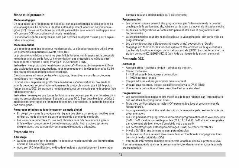
Mode multiprotocole Mode analogiqueOn peut aussi faire fonctionner le décodeur sur des installations ou des sections de voie analogiques. Le décodeur identifie automatiquement la tension de voie analo-gique (CC). Toutes les fonctions qui ont été paramétrée pour le mode analogique sous mfx ou sous DCC sont actives (voir mode numérique). Les fonctions sonores intégrées ne sont pas activées au départ d’usine pour l’exploi-tation analogique.
Mode numériqueLes décodeur sont des décodeur multiprotocole. Le décodeur peut être utilisé avec les protocoles numériques suivants : mfx, DCCLe protocole numérique offrant les possibilités les plus nombreuses est le protocole numérique à bit de poids fort. La hiérarchisation des protocoles numériques est descendante : Priorité 1 : mfx; Priorité 2 : DCC; Priorité 3 : DCIndication : des protocoles numériques peuvent s’influencer réciproquement. Pour une exploitation sans perturbations, nous recommandons de désactiver avec CV 50 des protocoles numériques non nécessaires.Dans la mesure où votre centrale les supporte, désactivez y aussi les protocoles numériques non nécessaires.Lorsque deux ou plusieurs protocoles numériques sont identifiés au niveau de la voie, le décodeur reprend automatiquement le protocole numérique à bit de poids fort, p. ex. mfx/DCC. Le protocole numérique mfx est donc repris par le décodeur (voir tableau antérieur).Indication : remarquez que toutes les fonctions ne peuvent pas être actionnées dans tous les protocoles numériques. Sous mfx et sous DCC, il est possible de procéder à quelques paramétrages de fonctions devant être actives dans le cadre de l’exploita-tion analogique.
Remarques relatives au fonctionnement en mode digital • En ce qui concerne la procédure de réglage des divers paramètres, veuillez vous
référer au mode d‘emploi de votre centrale de commande multitrain. • Les valeurs paramétrées d’usine sont choisies pour mfx de manière à garan-
tir le meilleur comportement de roulement possible. Pour d’autres systèmes d’exploitation, ces valeurs devront éventuellement être adaptées.
Protocole mfxAdressage • Aucune adresse n’est nécessaire, le décodeur reçoit toutefois une identification
unique et non équivoque (UID).• Avec son UID-identification, le décodeur indique automatiquement à une station
centrale ou à une station mobile qu’il est connecté.
Programmation• Les caractéristiques peuvent être programmées par l’intermédiaire de la couche
graphique de la station centrale, voire en partie aussi au moyen de la station mobile. • Toutes les configurations variables (CV) peuvent être lues et programmées de
façon réitérée.• La programmation peut être réalisée soit sur la voie principale, soit sur la voie de
programmation. • Les paramétrages par défaut (paramétrages usine) peuvent être rétablis.• Mappage des fonctions : les fonctions peuvent être affectées à de quelconques
touches de fonction au moyen de la station centrale (60212) (restreinte) et avec la station centrale 60213/60214/60215 (voir Aide au niveau de la station centrale).
Protocole DCCAdressage• Adresse brève – adresse longue – adresse de traction.• Champ d’adresse :
1 – 127 adresse brève, adresse de traction 1 – 10239 adresse longue
• Chaque adresse est programmable manuellement.• Une adresse courte ou longue est sélectionnée via la CV 29 (bit 5).• Une adresse de traction utilisée désactive l’adresse standard.
Programmation• Les caractéristiques peuvent être modifiées de façon réitérée par l’intermédiaire
des variables de configuration (CVs). • Toutes les configurations variables (CV) peuvent être lues et programmées de
façon réitérée.• La programmation peut être réalisée soit sur la voie principale, soit sur la voie de
programmation.• Les CVs peuvent être programmées librement (programmation de la voie principale
(PoM). PoM n’est pas possible pour les CV 1, 17, 18 et 29. PoM doit être supportée par votre centrale (voir mode d’emploi de votre appareil).
• Les paramétrages par défaut (paramétrages usine) peuvent être rétablis.• 14 voire 28/128 crans de marche sont paramétrables.• Toutes les fonctions peuvent être commutées en fonction du mappage des fonc-
tions (voir le descriptif des CVs).• Pour toute information complémentaire, voir le tableau des CVs, protocole DCC. Il est recommandé, de réaliser la programmation, fondamentalement, sur la voie de programmation.
14
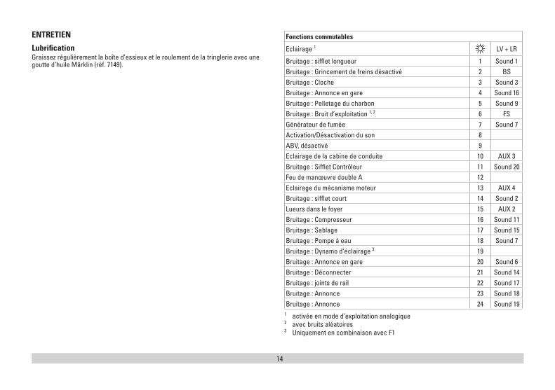
ENTRETIEN
Lubrification Graissez régulièrement la boîte d’essieux et le roulement de la tringlerie avec une goutte d’huile Märklin (réf. 7149).
Fonctions commutables
Eclairage 1 LV + LR
Bruitage : sifflet longueur 1 Sound 1Bruitage : Grincement de freins désactivé 2 BSBruitage : Cloche 3 Sound 3Bruitage : Annonce en gare 4 Sound 16Bruitage : Pelletage du charbon 5 Sound 9Bruitage : Bruit d’exploitation 1, 2 6 FSGénérateur de fumée 7 Sound 7Activation/Désactivation du son 8ABV, désactivé 9Eclairage de la cabine de conduite 10 AUX 3Bruitage : Sifflet Contrôleur 11 Sound 20Feu de manœuvre double A 12Eclairage du mécanisme moteur 13 AUX 4Bruitage : sifflet court 14 Sound 2Lueurs dans le foyer 15 AUX 2Bruitage : Compresseur 16 Sound 11Bruitage : Sablage 17 Sound 15Bruitage : Pompe à eau 18 Sound 7Bruitage : Dynamo d‘éclairage 3 19Bruitage : Annonce en gare 20 Sound 6Bruitage : Déconnecter 21 Sound 14Bruitage : joints de rail 22 Sound 17Bruitage : Annonce 23 Sound 18Bruitage : Annonce 24 Sound 19
1 activée en mode d’exploitation analogique2 avec bruits aléatoires 3 Uniquement en combinaison avec F1
15
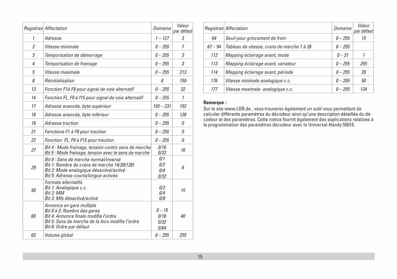
Registres Affectation Domaine Valeur par défaut
1 Adresse 1 – 127 3
2 Vitesse minimale 0 – 255 7
3 Temporisation de démarrage 0 – 255 3
4 Temporisation de freinage 0 – 255 3
5 Vitesse maximale 0 – 255 213
8 Réinitialisation 8 159
13 Fonction F1à F8 pour signal de voie alternatif 0 – 255 32
14 Fonction FL, F9 à f15 pour signal de voie alternatif 0 – 255 1
17 Adresse avancée, byte supérieur 192 – 231 192
18 Adresse avancée, byte inférieur 0 – 255 128
19 Adresse traction 0 – 255 0
21 Fonctions F1 à F8 pour traction 0 – 255 0
22 Fonction FL, F9 à F15 pour traction 0 – 255 0
27 Bit 4 : Mode freinage, tension contre sens de marche Bit 5 : Mode freinage, tension avec le sens de marche
0/16 0/32 16
29
Bit 0 : Sens de marche normal/inversé Bit 1: Nombre de crans de marche 14/28(128) Bit 2: Mode analogique désactivé/activé Bit 5: Adresse courte/longue activée
0/10/20/40/32
6
50
Formats alternatifs Bit 1: Analogique c.c. Bit 2: MM Bit 3: Mfx désactivé/activé
0/2 0/4 0/8
15
60
Annonce en gare multiple Bit 0 à 3: Nombre des gares Bit 4: Annonce finale modifie l’ordre Bit 5: Sens de marche de la loco modifie l’ordre Bit 6: Ordre par défaut
0 – 150/160/320/64
40
63 Volume global 0 – 255 255
Registres Affectation Domaine Valeur par défaut
64 Seuil pour grincement de frein 0 – 255 15
67 – 94 Tableau de vitesse, crans de marche 1 à 28 0 – 255
112 Mapping éclairage avant, mode 0 – 21 1
113 Mapping éclairage avant, variateur 0 – 255 255
114 Mapping éclairage avant, période 0 – 255 20
176 Vitesse minimale analogique c.c. 0 – 255 50
177 Vitesse maximale analogique c.c. 0 – 255 134
Remarque :Sur le site www.LGB.de , vous trouverez également un outil vous permettant de calculer différents paramètres du décodeur ainsi qu’une description détaillée du dé-codeur et des paramètres. Cette notice fournit également des explications relatives à la programmation des paramètres décodeur avec le Universal-Handy 55015.
16
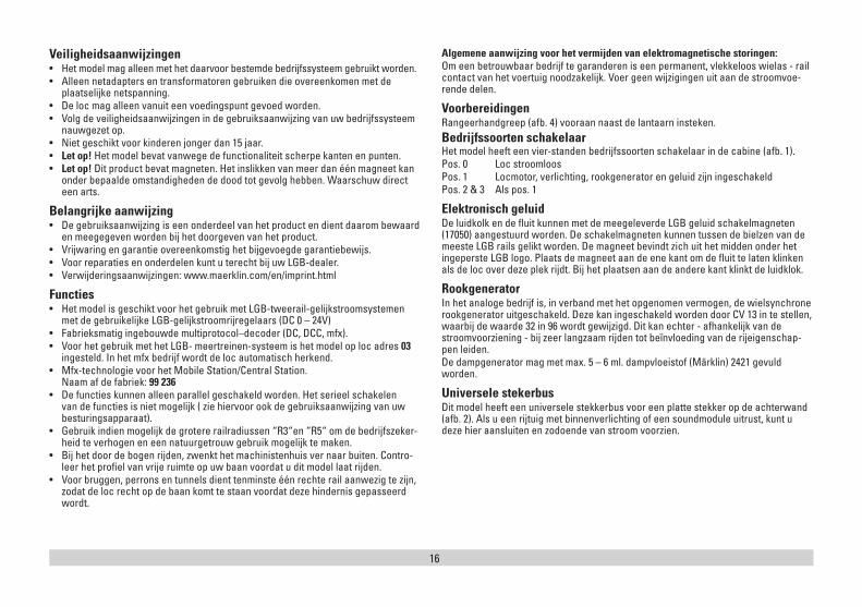
Veiligheidsaanwijzingen• Het model mag alleen met het daarvoor bestemde bedrijfssysteem gebruikt worden.• Alleen netadapters en transformatoren gebruiken die overeenkomen met de
plaatselijke netspanning.• De loc mag alleen vanuit een voedingspunt gevoed worden.• Volg de veiligheidsaanwijzingen in de gebruiksaanwijzing van uw bedrijfssysteem
nauwgezet op.• Niet geschikt voor kinderen jonger dan 15 jaar. • Let op! Het model bevat vanwege de functionaliteit scherpe kanten en punten. • Let op! Dit product bevat magneten. Het inslikken van meer dan één magneet kan
onder bepaalde omstandigheden de dood tot gevolg hebben. Waarschuw direct een arts.
Belangrijke aanwijzing• De gebruiksaanwijzing is een onderdeel van het product en dient daarom bewaard
en meegegeven worden bij het doorgeven van het product.• Vrijwaring en garantie overeenkomstig het bijgevoegde garantiebewijs.• Voor reparaties en onderdelen kunt u terecht bij uw LGB-dealer.• Verwijderingsaanwijzingen: www.maerklin.com/en/imprint.html
Functies• Het model is geschikt voor het gebruik met LGB-tweerail-gelijkstroomsystemen
met de gebruikelijke LGB-gelijkstroomrijregelaars (DC 0 – 24V)• Fabrieksmatig ingebouwde multiprotocol–decoder (DC, DCC, mfx).• Voor het gebruik met het LGB- meertreinen-systeem is het model op loc adres 03
ingesteld. In het mfx bedrijf wordt de loc automatisch herkend. • Mfx-technologie voor het Mobile Station/Central Station.
Naam af de fabriek: 99 236• De functies kunnen alleen parallel geschakeld worden. Het serieel schakelen
van de functies is niet mogelijk ( zie hiervoor ook de gebruiksaanwijzing van uw besturingsapparaat).
• Gebruik indien mogelijk de grotere railradiussen “R3“en “R5“ om de bedrijfszeker-heid te verhogen en een natuurgetrouw gebruik mogelijk te maken.
• Bij het door de bogen rijden, zwenkt het machinistenhuis ver naar buiten. Contro-leer het profiel van vrije ruimte op uw baan voordat u dit model laat rijden.
• Voor bruggen, perrons en tunnels dient tenminste één rechte rail aanwezig te zijn, zodat de loc recht op de baan komt te staan voordat deze hindernis gepasseerd wordt.
Algemene aanwijzing voor het vermijden van elektromagnetische storingen:Om een betrouwbaar bedrijf te garanderen is een permanent, vlekkeloos wielas - rail contact van het voertuig noodzakelijk. Voer geen wijzigingen uit aan de stroomvoe-rende delen.
VoorbereidingenRangeerhandgreep (afb. 4) vooraan naast de lantaarn insteken.Bedrijfssoorten schakelaarHet model heeft een vier-standen bedrijfssoorten schakelaar in de cabine (afb. 1). Pos. 0 Loc stroomloosPos. 1 Locmotor, verlichting, rookgenerator en geluid zijn ingeschakeldPos. 2 & 3 Als pos. 1
Elektronisch geluidDe luidkolk en de fluit kunnen met de meegeleverde LGB geluid schakelmagneten (17050) aangestuurd worden. De schakelmagneten kunnen tussen de bielzen van de meeste LGB rails gelikt worden. De magneet bevindt zich uit het midden onder het ingeperste LGB logo. Plaats de magneet aan de ene kant om de fluit te laten klinken als de loc over deze plek rijdt. Bij het plaatsen aan de andere kant klinkt de luidklok.
RookgeneratorIn het analoge bedrijf is, in verband met het opgenomen vermogen, de wielsynchrone rookgenerator uitgeschakeld. Deze kan ingeschakeld worden door CV 13 in te stellen, waarbij de waarde 32 in 96 wordt gewijzigd. Dit kan echter - afhankelijk van de stroomvoorziening - bij zeer langzaam rijden tot beïnvloeding van de rijeigenschap-pen leiden. De dampgenerator mag met max. 5 – 6 ml. dampvloeistof (Märklin) 2421 gevuld worden.
Universele stekerbusDit model heeft een universele stekkerbus voor een platte stekker op de achterwand (afb. 2). Als u een rijtuig met binnenverlichting of een soundmodule uitrust, kunt u deze hier aansluiten en zodoende van stroom voorzien.
17
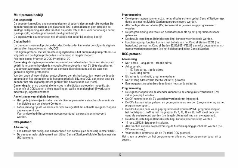
MultiprotocolbedrijfAnaloogbedrijfDe decoder kan ook op analoge modelbanen of spoortrajecten gebruikt worden. De decoder herkent de analoge gelijkspanning (DC) automatisch en past zich aan de analoge railspanning aan. Alle functies die onder mfx of DCC voor het analoge bedrijf zijn ingesteld, worden geactiveerd (zie digitaalbedrijf). De ingebouwde soundfuncties zijn af fabriek niet actief bij analoog bedrijf.
DigitaalbedrijfDe Decoder is een multiprotocoldecoder. De decoder kan onder de volgende digitale protocollen ingezet worden: mfx, DCC. Het digitaalprotocol met de meeste mogelijkheden is het primaire digitaalprotocol. De volgorde van de digitaalprotocollen is afnemend in mogelijkheden: Prioriteit 1: mfx; Prioriteit 2: DCC; Prioriteit 3: DCOpmerking: de digitale protocollen kunnen elkaar beïnvloeden. Voor een storingsvrij bedrijf is het aan te bevelen de niet gebruikte protocollen met CV 50 te deactiveren. Deactiveer eveneens, voor zover uw centrale dit ondersteunt, ook de daar niet gebruikte digitale protocollen. Worden twee of meer digitaal protocollen op de rails herkend, dan neemt de decoder automatisch het protocol met de hoogste prioriteit, bijv. mfx/DCC, dan wordt door de decoder het mfx-digitaalprotocol gebruikt (zie bovenstaand overzicht).Opmerking: let er op dat niet alle functies in alle digitaalprotocollen mogelijk zijn. Onder mfx of DCC kunnen enkele instellingen, welke in analoogbedrijf werkzaam moeten zijn, ingesteld worden.
Aanwijzingen voor digitale besturing • Het op de juiste wijze instellen van de diverse parameters staat beschreven in de
handleiding van uw digitale Centrale.• Fabrieksmatig zijn de waarden voor mfx zo ingestelt dat optimale rijeigenschappen
gegarandeerd zijn. Voor andere bedrijfssystemen moeten eventueel aanpassingen uitgevoerd worden.
mfx-protocolAdressering • Een adres is niet nodig, elke decoder heeft een éénmalig en éénduidig kenmerk (UID).• De decoder meldt zich vanzelf aan bij het Central Station of Mobile Station met zijn
UID-kenmerk.
Programmering • De eigenschappen kunnen m.b.v. het grafische scherm op het Central Station resp.
deels ook met het Mobile Station geprogrammeerd worden.• Alle configuratie variabelen (CV) kunnen vaker gelezen en geprogrammeerd
worden.• De programmering kan zowel op het hoofdspoor als op het programmeerspoor
gebeuren.• De default-instellingen (fabrieksinstelling) kunnen weer hersteld worden.• Functiemapping: functies kunnen met behulp van het Central Station 60212 (met
beperking) en met het Central Station 60213/60214/60215 aan elke gewenste functi-etoets worden toegewezen (zie het helpbestand in het Central Station.
DCC-protocolAdressering • Kort adres – lang adres – tractie adres• Adresbereik:
1 – 127 kort adres, tractie adres 1 – 10239 lang adres
• Elk adres is handmatig programmeerbaar.• Kort of lang adres wordt met CV 29 (bit 5) gekozen.• Een toegepast tractieadres deactiveert het standaardadres.
Programmering• De eigenschappen van de decoder kunnen via de configuratie variabelen (CV)
vaker gewijzigd worden.• De CV-nummers en de CV-waarden worden direct ingevoerd.• De CV’s kunnen vaker gelezen en geprogrammeerd worden (programmering op het
programmeerspoor).• De CV’s kunnen naar wens geprogrammeerd worden (PoM - programmering op
het hoofdspoor). PoM is niet mogelijk bij CV 1, 17, 18 en 29. PoM moet door uw centrale ondersteund worden (zie de gebruiksaanwijzing van uw apparaat).
• De default-instellingen (fabrieksinstelling) kunnen weer hersteld worden.• 14 resp. 28/128 rijstappen instelbaar.• Alle functies kunnen overeenkomstig de functiemapping geschakeld worden (zie
CV-beschrijving).• Voor verdere informatie, zie de CV-tabel DCC-protocol.Het is aan te bevelen om het programmeren alleen op het programmeerspoor uit te voeren.
18
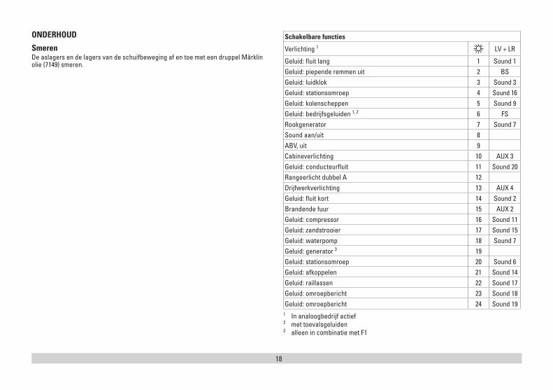
ONDERHOUD
Smeren De aslagers en de lagers van de schuifbeweging af en toe met een druppel Märklin olie (7149) smeren.
Schakelbare functies
Verlichting 1 LV + LR
Geluid: fluit lang 1 Sound 1Geluid: piepende remmen uit 2 BSGeluid: luidklok 3 Sound 3Geluid: stationsomroep 4 Sound 16Geluid: kolenscheppen 5 Sound 9Geluid: bedrijfsgeluiden 1, 2 6 FSRookgenerator 7 Sound 7Sound aan/uit 8ABV, uit 9Cabineverlichting 10 AUX 3Geluid: conducteurfluit 11 Sound 20Rangeerlicht dubbel A 12Drijfwerkverlichting 13 AUX 4Geluid: fluit kort 14 Sound 2Brandende fuur 15 AUX 2Geluid: compressor 16 Sound 11Geluid: zandstrooier 17 Sound 15Geluid: waterpomp 18 Sound 7Geluid: generator 3 19Geluid: stationsomroep 20 Sound 6Geluid: afkoppelen 21 Sound 14Geluid: raillassen 22 Sound 17Geluid: omroepbericht 23 Sound 18Geluid: omroepbericht 24 Sound 19
1 In analoogbedrijf actief 2 met toevalsgeluiden 3 alleen in combinatie met F1
19
Register Belegging Bereik Default
1 Adres 1 – 127 3
2 Minimumsnelheid 0 – 255 7
3 Optrekvertraging 0 – 255 3
4 Afremvertraging 0 – 255 3
5 Maximumsnelheid 0 – 255 213
8 Reset 8 159
13 Functie F1 – F8 bij alternatief railsignaal 0 – 255 32
14 Functie FL, F9 – f15 bij alternatief railsignaal 0 – 255 1
17 Lange adressering, hoogste byte 192 – 231 192
18 Lange adressering, laagste byte 0 – 255 128
19 Tractieadres 0 – 255 0
21 Functie F1 – F8 bij tractie 0 – 255 0
22 Functie FL, F9 – F15 bij tractie 0 – 255 0
27 Bit 4: remmodus spanning tegengesteld aan rijrichting Bit 5: remmodus spanning gelijk aan rijrichting
0/16 0/32 16
29
Bit 0: Rijrichting normaal/omgekeerd Bit 1: Aantal rijstappen 14/28(128) Bit 2: Analoogbedrijf uit/aan Bit 5: kort / lang adres actief
0/10/20/40/32
6
50
Alternatief formaat Bit 1: Analoog DC Bit 2: MM Bit 3: mfx uit/aan
0/2 0/4 0/8
15
60
Multi station omroep Bit 0 – 3: aantal stations Bit 4: eindstation omroep, volgorde wijzigt Bit 5: rijrichting wijzigt de volgorde Bit 6: voorwaarde voor volgorde
0 – 150/160/320/64
40
63 Totaal volume 0 – 255 255
64 Drempelwaarde voor piepende remmen 0 – 255 15
Register Belegging Bereik Default
67 – 94 Snelheidstabel voor rijstappen 1 - 28 0 – 255
112 Mapping licht voor, Modus 0 – 21 1
113 Mapping licht voor, dimmer 0 – 255 255
114 Mapping licht voor, periode 0 – 255 20
176 Minimumsnelheid analoog DC 0 – 255 50
177 Maximumsnelheid analoog DC 0 – 255 134
Opmerking:Op de website www.LGB.de vindt u een tool waarmee u de verschillende decoder-instelling kunt berekenen evenals een uitvoerige beschrijving van de decoder en zijn instellingen. In die handleiding wordt ook het programmeren van de decoderinstel-lingen met de universal-Handy 55015 uitgelegd.
20
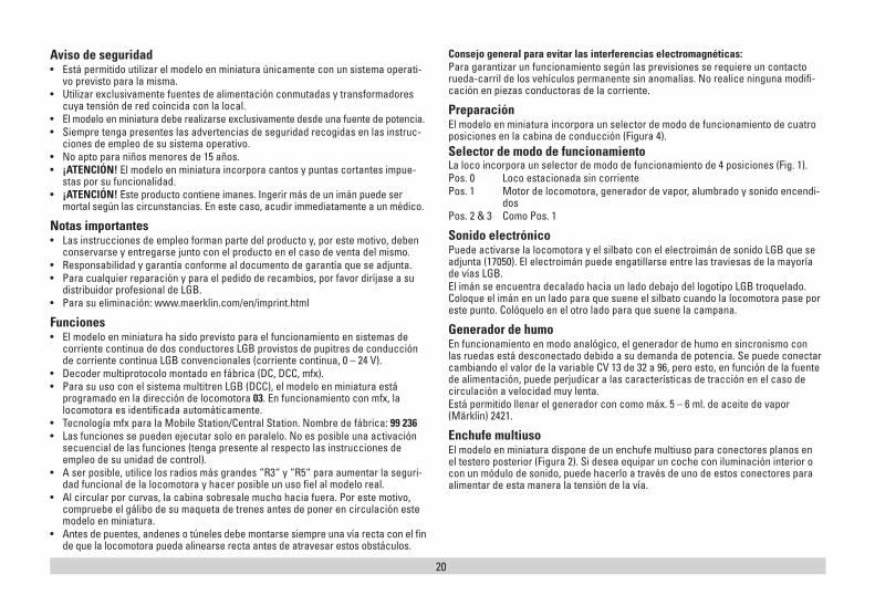
Aviso de seguridad• Está permitido utilizar el modelo en miniatura únicamente con un sistema operati-
vo previsto para la misma. • Utilizar exclusivamente fuentes de alimentación conmutadas y transformadores
cuya tensión de red coincida con la local.• El modelo en miniatura debe realizarse exclusivamente desde una fuente de potencia. • Siempre tenga presentes las advertencias de seguridad recogidas en las instruc-
ciones de empleo de su sistema operativo. • No apto para niños menores de 15 años.• ¡ATENCIÓN! El modelo en miniatura incorpora cantos y puntas cortantes impue-
stas por su funcionalidad. • ¡ATENCIÓN! Este producto contiene imanes. Ingerir más de un imán puede ser
mortal según las circunstancias. En este caso, acudir immediatamente a un médico.
Notas importantes• Las instrucciones de empleo forman parte del producto y, por este motivo, deben
conservarse y entregarse junto con el producto en el caso de venta del mismo.• Responsabilidad y garantía conforme al documento de garantía que se adjunta.• Para cualquier reparación y para el pedido de recambios, por favor diríjase a su
distribuidor profesional de LGB. • Para su eliminación: www.maerklin.com/en/imprint.html
Funciones• El modelo en miniatura ha sido previsto para el funcionamiento en sistemas de
corriente continua de dos conductores LGB provistos de pupitres de conducción de corriente continua LGB convencionales (corriente continua, 0 – 24 V).
• Decoder multiprotocolo montado en fábrica (DC, DCC, mfx).• Para su uso con el sistema multitren LGB (DCC), el modelo en miniatura está
programado en la dirección de locomotora 03. En funcionamiento con mfx, la locomotora es identificada automáticamente.
• Tecnología mfx para la Mobile Station/Central Station. Nombre de fábrica: 99 236• Las funciones se pueden ejecutar solo en paralelo. No es posible una activación
secuencial de las funciones (tenga presente al respecto las instrucciones de empleo de su unidad de control).
• A ser posible, utilice los radios más grandes “R3“ y “R5“ para aumentar la seguri-dad funcional de la locomotora y hacer posible un uso fiel al modelo real.
• Al circular por curvas, la cabina sobresale mucho hacia fuera. Por este motivo, compruebe el gálibo de su maqueta de trenes antes de poner en circulación este modelo en miniatura.
• Antes de puentes, andenes o túneles debe montarse siempre una vía recta con el fin de que la locomotora pueda alinearse recta antes de atravesar estos obstáculos.
Consejo general para evitar las interferencias electromagnéticas: Para garantizar un funcionamiento según las previsiones se requiere un contacto rueda-carril de los vehículos permanente sin anomalías. No realice ninguna modifi-cación en piezas conductoras de la corriente.
PreparaciónEl modelo en miniatura incorpora un selector de modo de funcionamiento de cuatro posiciones en la cabina de conducción (Figura 4). Selector de modo de funcionamiento La loco incorpora un selector de modo de funcionamiento de 4 posiciones (Fig. 1).Pos. 0 Loco estacionada sin corrientePos. 1 Motor de locomotora, generador de vapor, alumbrado y sonido encendi-
dosPos. 2 & 3 Como Pos. 1
Sonido electrónicoPuede activarse la locomotora y el silbato con el electroimán de sonido LGB que se adjunta (17050). El electroimán puede engatillarse entre las traviesas de la mayoría de vías LGB.El imán se encuentra decalado hacia un lado debajo del logotipo LGB troquelado. Coloque el imán en un lado para que suene el silbato cuando la locomotora pase por este punto. Colóquelo en el otro lado para que suene la campana.
Generador de humoEn funcionamiento en modo analógico, el generador de humo en sincronismo con las ruedas está desconectado debido a su demanda de potencia. Se puede conectar cambiando el valor de la variable CV 13 de 32 a 96, pero esto, en función de la fuente de alimentación, puede perjudicar a las características de tracción en el caso de circulación a velocidad muy lenta. Está permitido llenar el generador con como máx. 5 – 6 ml. de aceite de vapor (Märklin) 2421.
Enchufe multiusoEl modelo en miniatura dispone de un enchufe multiuso para conectores planos en el testero posterior (Figura 2). Si desea equipar un coche con iluminación interior o con un módulo de sonido, puede hacerlo a través de uno de estos conectores para alimentar de esta manera la tensión de la vía.
21
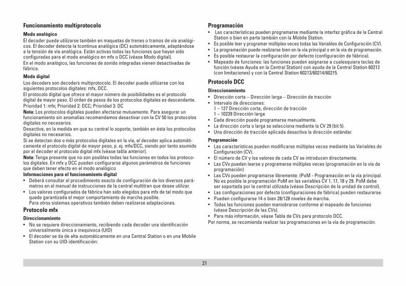
Funcionamiento multiprotocoloModo analógicoEl decoder puede utilizarse también en maquetas de trenes o tramos de vía analógi-cos. El decoder detecta la tcontinua analógica (DC) automáticamente, adaptándose a la tensión de vía analógica. Están activas todas las funciones que hayan sido configuradas para el modo analógico en mfx o DCC (véase Modo digital).En el modo analógico, las funciones de sonido integradas vienen desactivadas de fábrica.
Modo digitalLos decoders son decoders multiprotocolo. El decoder puede utilizarse con los siguientes protocolos digitales: mfx, DCC.El protocolo digital que ofrece el mayor número de posibilidades es el protocolo digital de mayor peso. El orden de pesos de los protocolos digitales es descendente.Prioridad 1: mfx; Prioridad 2: DCC; Prioridad 3: DCNota: Los protocolos digitales pueden afectarse mutuamente. Para asegurar un funcionamiento sin anomalías recomendamos desactivar con la CV 50 los protocolos digitales no necesarios.Desactive, en la medida en que su central lo soporte, también en ésta los protocolos digitales no necesarios.Si se detectan dos o más protocolos digitales en la vía, el decoder aplica automáti-camente el protocolo digital de mayor peso, p. ej. mfx/DCC, siendo por tanto asumido por el decoder el protocolo digital mfx (véase tabla anterior). Nota: Tenga presente que no son posibles todas las funciones en todos los protoco-los digitales. En mfx y DCC pueden configurarse algunos parámetros de funciones que deben tener efecto en el modo analógico Informaciones para el funcionamiento digital • Deberá consultar el procedimiento exacto de configuración de los diversos pará-
metros en el manual de instrucciones de la central multitren que desee utilizar. • Los valores configurados de fábrica han sido elegidos para mfx de tal modo que
quede garantizada el mejor comportamiento de marcha posible. Para otros sistemas operativos también deben realizarse adaptaciones.
Protocolo mfxDireccionamiento • No se requiere direccionamiento, recibiendo cada decoder una identificación
universalmente única e inequívoca (UID)• El decoder se da de alta automáticamente en una Central Station o en una Mobile
Station con su UID-identificación:
Programación• Las características pueden programarse mediante la interfaz gráfica de la Central
Station o bien en parte también con la Mobile Station.• Es posible leer y programar múltiples veces todas las Variables de Configuración (CV).• La programación puede realizarse bien en la vía principal o en la vía de programación.• Es posible restaurar la configuración por defecto (configuración de fábrica).• Mapeado de funciones: las funciones pueden asignarse a cualesquiera teclas de
función (véase Ayuda en la Central Station) con ayuda de la Central Station 60212 (con limitaciones) y con la Central Station 60213/60214/60215.
Protocolo DCCDireccionamiento• Dirección corta – Dirección larga – Dirección de tracción• Intervalo de direcciones:
1 – 127 Dirección corta, dirección de tracción 1 – 10239 Dirección larga
• Cada dirección puede programarse manualmente.• La dirección corta o larga se selecciona mediante la CV 29 (bit 5).• Una dirección de tracción aplicada desactiva la dirección estándar.
Programación• Las características pueden modificarse múltiples veces mediante las Variables de
Configuración (CV).• El número de CV y los valores de cada CV se introducen directamente.• Las CVs pueden leerse y programarse múltiples veces (programación en la vía de
programación)• Las CVs pueden programarse libremente. (PoM - Programación en la vía principal.
No es posible la programación PoM en las variables CV 1, 17, 18 y 29. PoM debe ser soportada por la central utilizada (véase Descripción de la unidad de control).
• Las configuraciones por defecto (configuraciones de fábrica) pueden restaurarse. • Pueden configurarse 14 o bien 28/128 niveles de marcha. • Todas las funciones pueden maniobrarse conforme al mapeado de funciones
(véase Descripción de las CVs).• Para más información, véase Tabla de CVs para protocolo DCC. Por norma, se recomienda realizar las programaciones en la vía de programación.
22
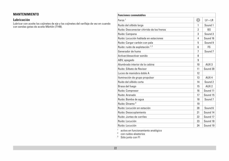
MANTENIMIENTO
Lubricación Lubricar con aceite los cojinetes de eje y los cojinetes del varillaje de vez en cuando con sendas gotas de aceite Märklin (7149).
Funciones conmutables
Faros 1 LV + LR
Ruido del silbido larga 1 Sound 1Ruido: Desconectar chirrido de los frenos 2 BSRuido: Campana 3 Sound 3Ruido: Locución hablada en estaciones 4 Sound 16Ruido: Cargar carbón con pala 5 Sound 9Ruido: ruido de explotación 1, 2 6 FSGenerador de humo 7 Sound 7Activar/desactivar sonido 8ABV, apagado 9Alumbrado interior de la cabina 10 AUX 3Ruido: Silbato de Revisor 11 Sound 20Luces de maniobra doble A 12Iluminación de grupo propulsor 13 AUX 4Ruido del silbido corta 14 Sound 2Brasa del fuego 15 AUX 2Ruido: Compresor 16 Sound 11Ruido: Arenado 17 Sound 15Ruido: Bomba de agua 18 Sound 7Ruido: Dinamo 3 19Ruido: Locución en estación 20 Sound 6Ruido: Desacoplamiento 21 Sound 14Ruido: Juntas de carriles 22 Sound 17Ruido: Locución 23 Sound 18Ruido: Locución 24 Sound 19
1 activo en funcionamiento analógico 2 con ruidos aleatorios 3 Sólo junto con F1
23
Registro Configuración Rango Valor por defecto
1 Dirección 1 – 127 3
2 Velocidad mínima 0 – 255 7
3 Retardo de arranque 0 – 255 3
4 Retardo de frenado 0 – 255 3
5 Velocidad máxima 0 – 255 213
8 Reset 8 159
13 Función F1 – F8 con señal de vía alternativa 0 – 255 32
14 Función FL, F9 – F15 con señal de vía alternativa 0 – 255 1
17 Dirección ampliada, byte de mayor peso 192 – 231 192
18 Dirección ampliada, byte de menor peso 0 – 255 128
19 Dirección de tracción 0 – 255 0
21 Funciones F1 – F8 en tracción 0 – 255 0
22 Función FL, F9 – F15 en tracción 0 – 255 0
27Bit 4: Modo de frenado Tensión en contra del sentido de marcha Bit 5: Modo de frenado Tensión a favor del sentido de marcha
0/16 0/32 16
29
Bit 0: Sentido de marcha normal/inversoBit 1: Número de niveles de marcha 14/28(128)Bit 2: Desactivar/activar funcionamiento analógicoBit 5: Dirección corta/larga activa
0/10/20/40/32
6
50
Formatos alternativosBit 1: Analógico DC Bit 2: MM Bit 3: desactivar/activar mfx
0/2 0/4 0/8
15
60
Locución multiestaciónBit 0 – 3: Número de estacionesBit 4: La locución final cambia el ordenBit 5: El sentido de circulación de la locomotora cambia el ordenBit 6: Consigna de orden de reproducción de locuciones
0 – 150/160/320/64
40
Registro Configuración Rango Valor por defecto
63 Volumen total 0 – 255 255
64 Umbral para chirrido de frenos 0 – 255 15
67 – 94 Tabla de velocidades de niveles de marcha 1 – 28 0 – 255
112 Mapeado de luces de cabeza, modo 0 – 21 1
113 Mapeado de luces de cabeza, regulador de intensi-dad lumínica 0 – 255 255
114 Mapeado de luces de cabeza, período 0 – 255 20
176 Velocidad mínima en formato analógico DC 0 – 255 50
177 Velocidad máxima en formato analógico DC 0 – 255 134
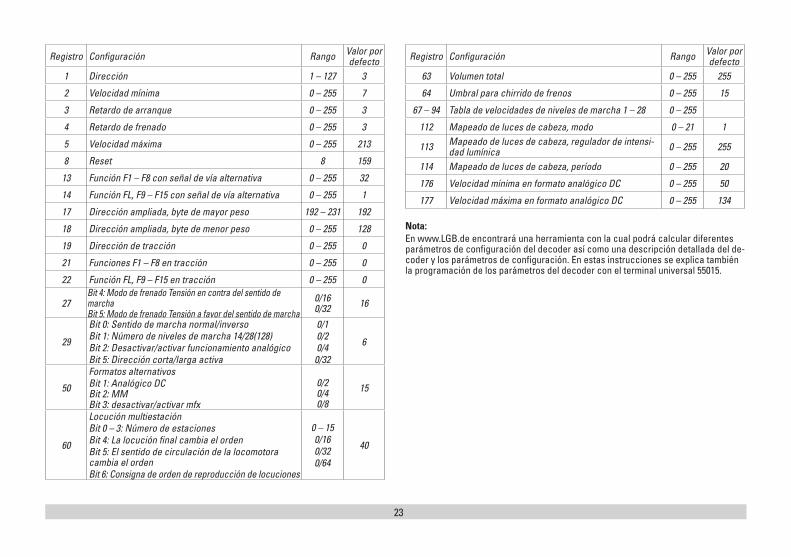
Nota:En www.LGB.de encontrará una herramienta con la cual podrá calcular diferentes parámetros de configuración del decoder así como una descripción detallada del de-coder y los parámetros de configuración. En estas instrucciones se explica también la programación de los parámetros del decoder con el terminal universal 55015.
24
Avvertenze per la siccurezza• Tale modello deve venire impiegato soltanto con un sistema di funzionamento
adeguato a tale scopo. • Utilizzare soltanto alimentatori “switching” da rete e trasformatori che corrispon-
dono alla Vostra tensione di rete locale.• Tale modello deve venire alimentato solo a partire da una sola sorgente di potenza. • Prestate attenzione assolutamente alle avvertenze di sicurezza nelle istruzioni di
impiego del Vostro sistema di funzionamento. • Non adatto per i bambini sotto i 15 anni.• AVVERTENZA! Per motivi funzionali i bordi e le punte sono spigolosi. • AVVERTENZA! Questo prodotto contiene magneti. L‘ingestione di più di un magnete
può causare la morte. In caso di ingestione informare immediatamente un medico.
Avvertenze importanti• Le istruzioni di impiego sono parte costitutiva del prodotto e devono pertanto ve-
nire preservate nonché consegnate in dotazione in caso di cessione del prodotto.• Prestazioni di garanzia e garanzia in conformità all’accluso certificato di garanzia.• Per le riparazioni o le parti di ricambio, contrattare il rivenditore LGB. • Smaltimento: www.maerklin.com/en/imprint.html
Funzioni• Tale modello è predisposto per il funzionamento su sistemi LGB in corrente con-
tinua a due rotaie con i tradizionali regolatori di marcia LGB a corrente continua (DC, 0 – 24 V).
• Decoder multiprotocollo (DC, DCC, mfx) incorporato di fabbrica. • Per l’impiego con il sistema LGB per numerosi treni (DCC) tale modello è pro-
grammato sull’indirizzo da locomotiva 03. Nel funzionamento con mfx la locomotiva viene riconosciuta automaticamente.
• Tecnologia Mfx per Mobile Station/Central Station. Nome di fabbrica: 99 236• Le funzioni possono venire messe in azione solo in modo parallelo. L’azionamento
seriale delle funzioni non è possibile (prestate attenzione a questo proposito alle istruzioni del Vostro apparato di comando).
• Utilizzate a seconda delle possibilità i raggi più grandi “R3” e ”R5“, per accrescere la sicurezza di esercizio e per consentire un esercizio fedele al prototipo.
• Durante la percorrenza di curve la cabina di guida sporge ampiamente verso l’esterno. Verificate pertanto il profilo della sagoma limite del Vostro impianto, prima che facciate viaggiare tale modello.
• Prima di ponti, banchine di stazione oppure gallerie dovrebbe necessariamente venire installato un binario diritto, in modo che la locomotiva possa allinearsi in rettilineo, prima che essa oltrepassi gli impedimenti.
Avvertenza generale per la prevenzione di disturbi elettromagnetici: Per garantire l’esercizio conforme alla destinazione è necessario un contatto ruota-rotaia dei rotabili permanente, esente da interruzioni. Non eseguite alcuna modifica-zione ai componenti conduttori di corrente.
PreparazioneInnestare i mancorrenti di manovra (Figura 4) anteriori accanto ai fanali. Commutatori del tipo di esercizio Tale modello ha un commutatore del tipo di esercizio a quattro posizioni nella cabina di guida (Fig. 1).Posiz. 0 Locomotiva accantonata senza correntePosiz. 1 Motore della locomotiva, generatore di vapore, illuminazione e effetti
sonori attivatiPosiz. 2 & 3 come Posiz. 1
Effetti sonori elettroniciCampana e fischio possono venire emessi con gli acclusi magneti di commutazi-one sonora LGB (17050). Il magnete di commutazione si può innestare a scatto tra le traversine della maggior parte dei binari LGB. Tale magnete si trova spostato lateralmente sotto il marchio LGB stampigliato. Collocate il magnete da un lato, per fare emettere il fischio quando la locomotiva passa sopra questo punto. In caso di disposizione sull’altro lato risuona la campana.
Apparato fumogenoNel funzionamento analogico il generatore di fumo sincronizzato alle ruote è disattivato in ragione del fabbisogno di potenza. Questo può venire attivato mediante impostazione della CV 13 dal valore 32 al valore 96, tuttavia questo – a seconda dell’alimentazione di corrente – può condurre al peggioramento delle caratteristiche di marcia con una marcia molto lenta. Il generatore di vapore deve venire riempito al max. con 5 – 6 ml di olio vaporizzabile (Märklin) 2421.
Presa a innesto per uso promiscuoTale modello ha una presa a innesto di uso promiscuo per spina innestabile piatta sulla parete posteriore (Figura 2). Qualora Voi equipaggiate una carrozza con illumi-nazione interna oppure con un modulo sonoro, questa potete allora collegarla qui ed alimentarla così con la tensione del binario.
25
Esercizio multi-protocolloEsercizio analogicoTale Decoder può venire fatto funzionare anche su impianti o sezioni di binario analogi-che. Il Decoder riconosce automaticamente la tensione analogica (DC) e si adegua alla tensione analogica del binario. Vi sono attive tutte le funzioni che erano state impostate per l’esercizio analogico sotto mfx oppure DCC (si veda esercizio Digital).Le funzionalità sonore incorporate non sono attive di fabbrica nell’esercizio analogico.
Esercizio DigitalI Decoder sono Decoder multi-protocollo. Il Decoder può venire impiegato sotto i seguenti protocolli Digital: mfx, DCC.Il protocollo Digital con il maggior numero di possibilità è il protocollo digitale di massimo valore. La sequenza dei protocolli Digital, con valori decrescenti, è: Priorità 1: mfx; Priorità 2: DCC; Priorità 3: DCAvvertenza: I protocolli Digital possono influenzarsi reciprocamente. Per un esercizio esente da inconvenienti noi consigliamo di disattivare con la CV 50 i protocolli Digital non necessari.Qualora la Vostra centrale li supporti, vogliate disattivare anche lì i protocolli Digital non necessari.Qualora sul binario vengano riconosciuti due o più protocolli Digital, il Decoder accetta automaticamente il protocollo Digital di valore più elevato. Ad es. mfx/DCC, in tal modo viene accettato dal Decoder il protocollo Digital mfx (si veda la precedente tabella).Avvertenza: Prestate attenzione al fatto che non tutte le funzioni sono possibili in tutti i protocolli Digital. Sotto mfx e DCC possono venire eseguite alcune impostazioni di funzioni, le quali saranno efficaci nell’esercizio analogico.Istruzioni per la funzione digitale • L’esatto procedimento per l’impostazione dei differenti parametri siete pregati di
ricavarlo dalle istruzioni di servizio della Vostra centrale per molti treni. • I valori impostati dalla fabbrica sono selezionati per mfx, cosicché sia garantito un
comportamento di marcia migliore possibile. Per altri sistemi di funzionamento se necessario devono venire apportati degli adattamenti.
Protocollo mfxIndirizzamento• Nessun indirizzo necessario, ciascun Decoder riceve una sua identificazione
irripetibile e univoca (UID).• Il Decoder si annuncia automaticamente ad una Central Station oppure Mobile
Station con il suo UID-identificazione.
Programmazione• Le caratteristiche possono venire programmate tramite la superficie grafica della
Central Station o rispettivamente in parte anche con la Mobile Station.• Tutte le Variabili di Configurazione (CV) possono venire ripetutamente lette e
programmate.• Tale programmazione può avvenire sui binari principali oppure sul binario di
programmazione.• Le impostazioni di default (impostazioni di fabbrica) possono venire nuovamente
riprodotte.• Mappatura delle funzioni: con l’ausilio della Central Station 60212 (limitatamente)
e con la Central Station 60213/60214/60215 le funzioni possono venire assegnate a dei tasti funzione a piacere (si vedano le guide di aiuto nella Central Station).
Protocollo DCCIndirizzamento• Indirizzo breve – Indirizzo lungo – Indirizzo unità di trazione• Ambito degli indirizzi:
da 1 a 127 indirizzo breve, indirizzo unità di trazione da 1 a 10239 indirizzo lungo.• Ciascun indirizzo è programmabile manualmente.• L’indirizzo breve oppure lungo viene selezionato tramite la CV 29 (Bit 5).• Un indirizzo di unità di trazione utilizzato disattiva l’indirizzo standard.
Programmazione• Le caratteristiche possono venire ripetutamente modificate tramite le Variabili di
Configurazione (CV).• Il numero della CV ed i valori della CV vengono introdotti direttamente.• Le CV possono venire ripetutamente lette e programmate (Programmazione sul
binario di programmazione).• Le CV possono venire programmate a piacere (PoM - programmazione sul binario
principale). PoM non è possibile nel caso delle CV 1, 17, 18 e 29. PoM deve venire sup-portata dalla Vostra centrale (si vedano le istruzioni di impiego del Vostro apparato).
• Le impostazioni di default (impostazioni di fabbrica) possono venire nuovamente riprodotte.
• 14 o rispettivamente 28/128 gradazioni di marcia impostabili.• Tutte le funzioni possono venire commutate in modo rispondente alla mappatura
delle funzioni (si veda la descrizione delle CV).• Per ulteriori informazioni, si veda la tabella delle CV nel protocollo DCC.È consigliabile intraprendere le programmazioni essenzialmente sul binario di programmazione.
26
MANUTENZIONE
Lubrificazione Di tanto in tanto oliare i cuscinetti degli assi e le boccole dei biellismi con una goccia di olio Märklin (7149) per ciascuno.
Funzioni commutabili
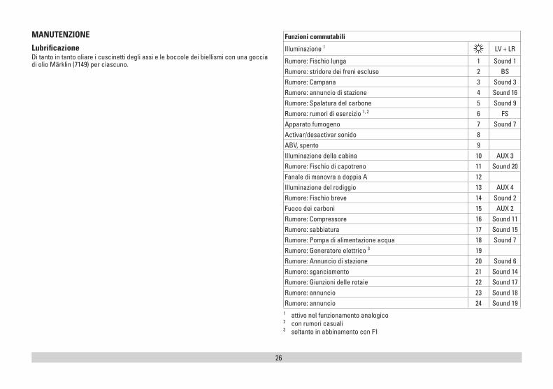
Illuminazione 1 LV + LR
Rumore: Fischio lunga 1 Sound 1Rumore: stridore dei freni escluso 2 BSRumore: Campana 3 Sound 3Rumore: annuncio di stazione 4 Sound 16Rumore: Spalatura del carbone 5 Sound 9Rumore: rumori di esercizio 1, 2 6 FSApparato fumogeno 7 Sound 7Activar/desactivar sonido 8ABV, spento 9Illuminazione della cabina 10 AUX 3Rumore: Fischio di capotreno 11 Sound 20Fanale di manovra a doppia A 12Illuminazione del rodiggio 13 AUX 4Rumore: Fischio breve 14 Sound 2Fuoco dei carboni 15 AUX 2Rumore: Compressore 16 Sound 11Rumore: sabbiatura 17 Sound 15Rumore: Pompa di alimentazione acqua 18 Sound 7Rumore: Generatore elettrico 3 19Rumore: Annuncio di stazione 20 Sound 6Rumore: sganciamento 21 Sound 14Rumore: Giunzioni delle rotaie 22 Sound 17Rumore: annuncio 23 Sound 18Rumore: annuncio 24 Sound 19
1 attivo nel funzionamento analogico 2 con rumori casuali 3 soltanto in abbinamento con F1
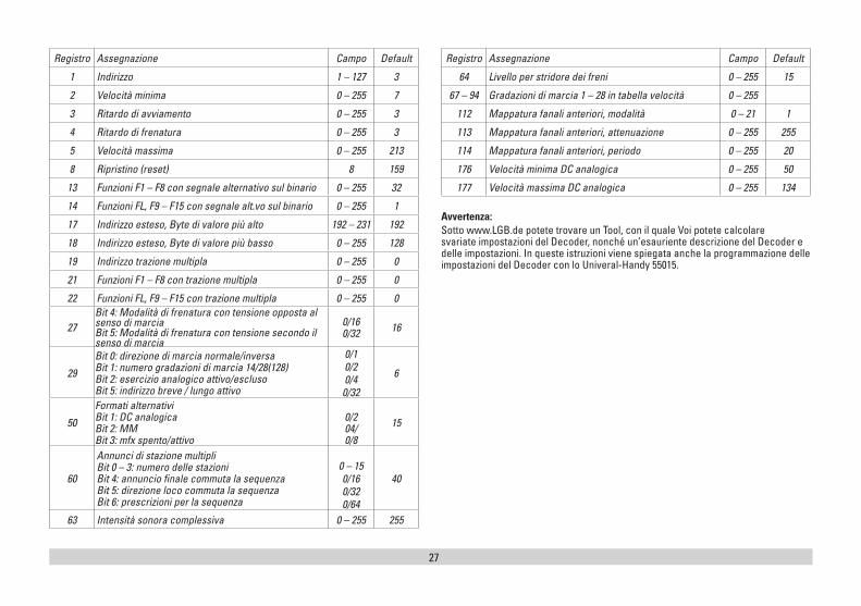
27
Registro Assegnazione Campo Default
1 Indirizzo 1 – 127 3
2 Velocità minima 0 – 255 7
3 Ritardo di avviamento 0 – 255 3
4 Ritardo di frenatura 0 – 255 3
5 Velocità massima 0 – 255 213
8 Ripristino (reset) 8 159
13 Funzioni F1 – F8 con segnale alternativo sul binario 0 – 255 32
14 Funzioni FL, F9 – F15 con segnale alt.vo sul binario 0 – 255 1
17 Indirizzo esteso, Byte di valore più alto 192 – 231 192
18 Indirizzo esteso, Byte di valore più basso 0 – 255 128
19 Indirizzo trazione multipla 0 – 255 0
21 Funzioni F1 – F8 con trazione multipla 0 – 255 0
22 Funzioni FL, F9 – F15 con trazione multipla 0 – 255 0
27Bit 4: Modalità di frenatura con tensione opposta al senso di marcia Bit 5: Modalità di frenatura con tensione secondo il senso di marcia
0/16 0/32 16
29
Bit 0: direzione di marcia normale/inversa Bit 1: numero gradazioni di marcia 14/28(128) Bit 2: esercizio analogico attivo/escluso Bit 5: indirizzo breve / lungo attivo
0/10/20/40/32
6
50
Formati alternativi Bit 1: DC analogica Bit 2: MM Bit 3: mfx spento/attivo
0/2 04/ 0/8
15
60
Annunci di stazione multipli Bit 0 – 3: numero delle stazioni Bit 4: annuncio finale commuta la sequenza Bit 5: direzione loco commuta la sequenza Bit 6: prescrizioni per la sequenza
0 – 150/160/320/64
40
63 Intensità sonora complessiva 0 – 255 255
Registro Assegnazione Campo Default
64 Livello per stridore dei freni 0 – 255 15
67 – 94 Gradazioni di marcia 1 – 28 in tabella velocità 0 – 255
112 Mappatura fanali anteriori, modalità 0 – 21 1
113 Mappatura fanali anteriori, attenuazione 0 – 255 255
114 Mappatura fanali anteriori, periodo 0 – 255 20
176 Velocità minima DC analogica 0 – 255 50
177 Velocità massima DC analogica 0 – 255 134
Avvertenza:Sotto www.LGB.de potete trovare un Tool, con il quale Voi potete calcolare svariate impostazioni del Decoder, nonché un’esauriente descrizione del Decoder e delle impostazioni. In queste istruzioni viene spiegata anche la programmazione delle impostazioni del Decoder con lo Univeral-Handy 55015.
28
0 1 2 3
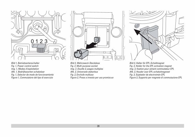
Bild 1, BetriebsartenschalterFig. 1, Power control switchImg. 1, Modes d‘exploitationAfb. 1, Bedrijfssoorten schakelaarFig. 1, Selector de modo de funcionamientoFigure 1, Commutatore del tipo di esercizio
Bild 2, Mehrzweck-SteckdoseFig. 2, Multi-purpose socketImg. 2, Douille à usages multiplesAfb. 2, Universele stekerbusFig. 2, Enchufe multiusoFigure 2, Presa a innesto per uso promiscuo
Bild 3, Halter für EPL-SchaltmagnetFig. 3, Holder for the EPL activation magnetImg. 3, fixation pour aimant commutateur EPLAfb. 3, Houder voor EPL-schakelmagneetFig. 3, Sujetador de electroimán EPLFigure 3, Supporto per magnete di commutazione EPL
29
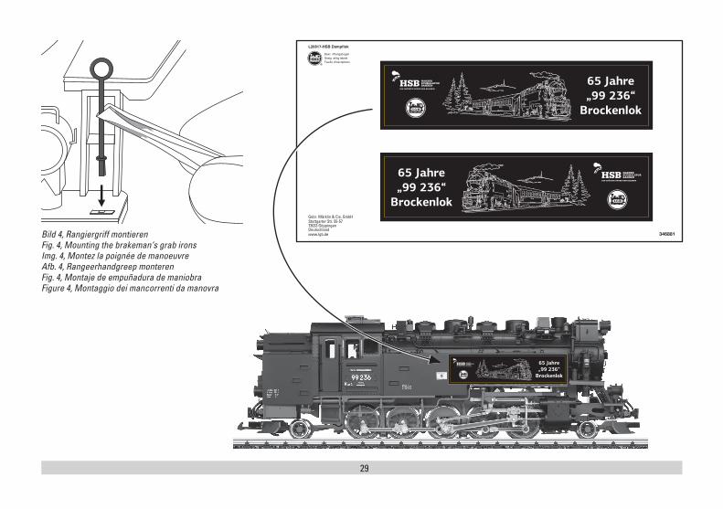
Bild 4, Rangiergriff montierenFig. 4, Mounting the brakeman‘s grab ironsImg. 4, Montez la poignée de manoeuvreAfb. 4, Rangeerhandgreep monterenFig. 4, Montaje de empuñadura de maniobraFigure 4, Montaggio dei mancorrenti da manovra
30
8
15
23
17
23
21
21
21
21
24
48
50
21
21
21
21
15
21
21
15
21 2222
22
26
2515
49
21
21
21
2125
25
21
21
17
2126 26
21
21
31
4
6
1
55
67
2
1618
18
3
6
6
16
17
20
16
16
16
20
20
2
1
20
19
20
20
20
16 6
6
6
6
Details der Darstellung können von dem Modell abweichen.
32
824
22
22 22
22
23 2323
15
21
15
15
11
Details der D
arstellung können von dem
Modell
abweichen.
10
13
14
10
15
10
12
12
13
15
15
1210
15
21
13
913
13
33
24
27
29
29
31
29
30
15
15
2815
15
24
24
28
28
28
28
47
24
27
46
2121
2121
45 21
32
21
21
2143
37
33
3333
33
15
3744
21
21 3644
45
3639
45
35
1651
21
34
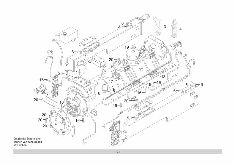
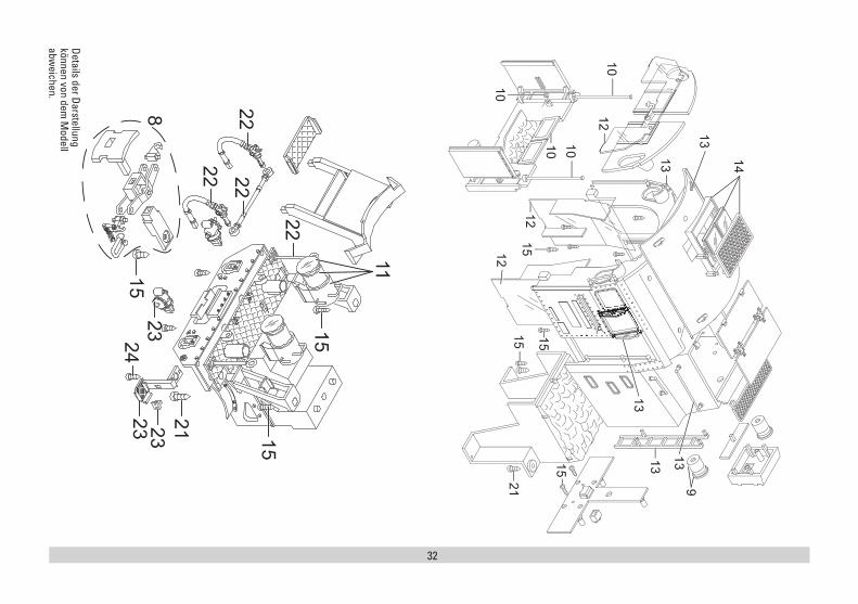
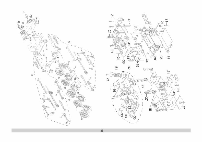
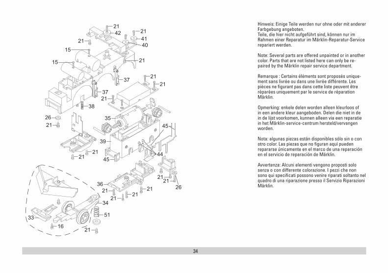
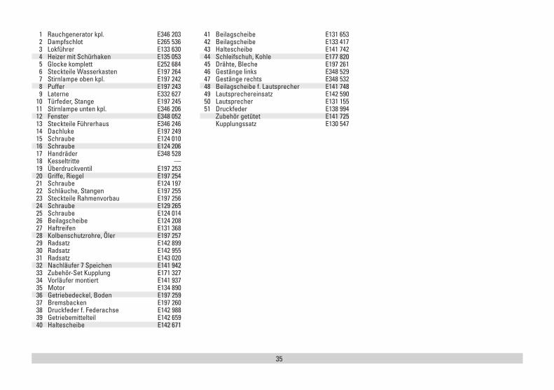
Hinweis: Einige Teile werden nur ohne oder mit anderer Farbgebung angeboten. Teile, die hier nicht aufgeführt sind, können nur im Rahmen einer Reparatur im Märklin-Reparatur-Service repariert werden.
Note: Several parts are offered unpainted or in another color. Parts that are not listed here can only be re-paired by the Märklin repair service department.
Remarque : Certains éléments sont proposés unique-ment sans livrée ou dans une livrée différente. Les pièces ne figurant pas dans cette liste peuvent être réparées uniquement par le service de réparation Märklin.
Opmerking: enkele delen worden alleen kleurloos of in een andere kleur aangeboden. Delen die niet in de in de lijst voorkomen, kunnen alleen via een reparatie in het Märklin-service-centrum hersteld/vervangen worden.
Nota: algunas piezas están disponibles sólo sin o con otro color. Las piezas que no figuran aquí pueden repararse únicamente en el marco de una reparación en el servicio de reparación de Märklin.
Avvertenza: Alcuni elementi vengono proposti solo senza o con differente colorazione. I pezzi che non sono qui specificati possono venire riparati soltanto nel quadro di una riparazione presso il Servizio Riparazioni Märklin.
16
2121
38
37
37 21
21
212142
4140
21
21
44
2621
21
33
21
45
45
2121
21
26
21
15
15
51
34
2121
36
39
35
35
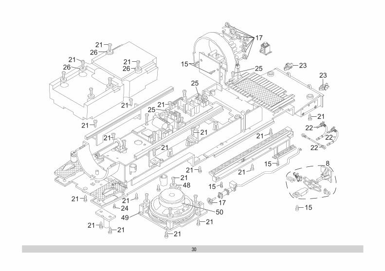
1 Rauchgenerator kpl. E346 203 2 Dampfschlot E265 536 3 Lokführer E133 630 4 Heizer mit Schürhaken E135 053 5 Glocke komplett E252 684 6 Steckteile Wasserkasten E197 264 7 Stirnlampe oben kpl. E197 242 8 Puffer E197 243 9 Laterne E332 627 10 Türfeder, Stange E197 245 11 Stirnlampe unten kpl. E346 206 12 Fenster E348 052 13 Steckteile Führerhaus E346 246 14 Dachluke E197 249 15 Schraube E124 010 16 Schraube E124 206 17 Handräder E348 528 18 Kesseltritte — 19 Überdruckventil E197 253 20 Griffe, Riegel E197 254 21 Schraube E124 197 22 Schläuche, Stangen E197 255 23 Steckteile Rahmenvorbau E197 256 24 Schraube E129 265 25 Schraube E124 014 26 Beilagscheibe E124 208 27 Haftreifen E131 368 28 Kolbenschutzrohre, Öler E197 257 29 Radsatz E142 899 30 Radsatz E142 955 31 Radsatz E143 020 32 Nachläufer 7 Speichen E141 942 33 Zubehör-Set Kupplung E171 327 34 Vorläufer montiert E141 937 35 Motor E134 890 36 Getriebedeckel, Boden E197 259 37 Bremsbacken E197 260 38 Druckfeder f. Federachse E142 988 39 Getriebemittelteil E142 659 40 Haltescheibe E142 671
41 Beilagscheibe E131 653 42 Beilagscheibe E133 417 43 Haltescheibe E141 742 44 Schleifschuh, Kohle E177 820 45 Drähte, Bleche E197 261 46 Gestänge links E348 529 47 Gestänge rechts E348 532 48 Beilagscheibe f. Lautsprecher E141 748 49 Lautsprechereinsatz E142 590 50 Lautsprecher E131 155 51 Druckfeder E138 994 Zubehör getütet E141 725 Kupplungssatz E130 547

Gebr. Märklin & Cie. GmbH Stuttgarter Straße 55 - 57 73033 Göppingen Germany www.lgb.de
359731/0521/Sm1EfÄnderungen vorbehalten
© Gebr. Märklin & Cie. GmbHwww.maerklin.com/en/imprint.html
Erweiterte Decoderwerte, Werkseinstellung
26817
2
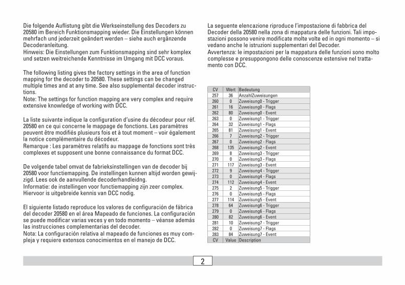
CV Wert Bedeutung257 36 AnzahlZuweisungen260 0 Zuweisung0 - Trigger261 16 Zuweisung0 - Flags262 80 Zuweisung0 - Event263 0 Zuweisung1 - Trigger264 32 Zuweisung1 - Flags265 81 Zuweisung1 - Event266 7 Zuweisung2 - Trigger267 0 Zuweisung2 - Flags268 135 Zuweisung2 - Event269 8 Zuweisung3 - Trigger270 0 Zuweisung3 - Flags271 117 Zuweisung3 - Event272 9 Zuweisung4 - Trigger273 0 Zuweisung4 - Flags274 112 Zuweisung4 - Event275 2 Zuweisung5 - Trigger276 0 Zuweisung5 - Flags277 114 Zuweisung5 - Event278 64 Zuweisung6 - Trigger279 0 Zuweisung6 - Flags280 82 Zuweisung6 - Event281 10 Zuweisung7 - Trigger282 0 Zuweisung7 - Flags283 84 Zuweisung7 - EventCV Value Description
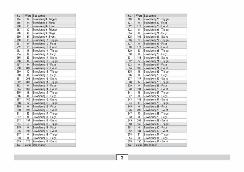
Die folgende Auflistung gibt die Werkseinstellung des Decoders zu 20580 im Bereich Funktionsmapping wieder. Die Einstellungen können mehrfach und jederzeit geändert werden – siehe auch ergänzende Decoderanleitung. Hinweis: Die Einstellungen zum Funktionsmapping sind sehr komplex und setzen weitreichende Kenntnisse im Umgang mit DCC voraus.
The following listing gives the factory settings in the area of function mapping for the decoder to 20580. These settings can be changed multiple times and at any time. See also supplemental decoder instruc-tions. Note: The settings for function mapping are very complex and require extensive knowledge of working with DCC.
La liste suivante indique la configuration d‘usine du décodeur pour réf. 20580 en ce qui concerne le mappage de fonctions. Les paramètres peuvent être modifiés plusieurs fois et à tout moment – voir également la notice complémentaire du décodeur. Remarque : Les paramètres relatifs au mappage de fonctions sont très complexes et supposent une bonne connaissance du format DCC.
De volgende tabel omvat de fabrieksinstellingen van de decoder bij 20580 voor functiemapping. De instellingen kunnen altijd worden gewij-zigd. Lees ook de aanvullende decoderhandleidng. Informatie: de instellingen voor functiemapping zijn zeer complex. Hiervoor is uitgebreide kennis van DCC nodig.
El siguiente listado reproduce los valores de configuración de fábrica del decoder 20580 en el área Mapeado de funciones. La configuración se puede modificar varias veces y en todo momento – véanse además las instrucciones complementarias del decoder. Nota: La configuración relativa al mapeado de funciones es muy com-pleja y requiere extensos conocimientos en el manejo de DCC.
La seguente elencazione riproduce l’impostazione di fabbrica del Decoder della 20580 nella zona di mappatura delle funzioni. Tali impo-stazioni possono venire modificate molte volte ed in ogni momento – si vedano anche le istruzioni supplementari del Decoder. Avvertenza: le impostazioni per la mappatura delle funzioni sono molto complesse e presuppongono delle conoscenze estensive nel tratta-mento con DCC.
3
CV Wert Bedeutung320 14 Zuweisung20 - Trigger321 0 Zuweisung20 - Flags322 178 Zuweisung20 - Event323 11 Zuweisung21 - Trigger324 0 Zuweisung21 - Flags325 196 Zuweisung21 - Event326 68 Zuweisung22 - Trigger327 0 Zuweisung22 - Flags328 177 Zuweisung22 - Event329 20 Zuweisung23 - Trigger330 0 Zuweisung23 - Flags331 182 Zuweisung23 - Event332 5 Zuweisung24 - Trigger333 0 Zuweisung24 - Flags334 185 Zuweisung24 - Event335 16 Zuweisung25 - Trigger336 0 Zuweisung25 - Flags337 187 Zuweisung25 - Event338 17 Zuweisung26 - Trigger339 0 Zuweisung26 - Flags340 191 Zuweisung26 - Event341 18 Zuweisung27 - Trigger342 0 Zuweisung27 - Flags343 183 Zuweisung27 - Event344 13 Zuweisung28 - Trigger345 0 Zuweisung28 - Flags346 208 Zuweisung28 - Event347 10 Zuweisung29 - Trigger348 0 Zuweisung29 - Flags349 208 Zuweisung29 - Event350 160 Zuweisung30 - Trigger351 0 Zuweisung30 - Flags352 184 Zuweisung30 - Event353 21 Zuweisung31 - Trigger354 0 Zuweisung31 - Flags355 190 Zuweisung31 - EventCV Value Description
CV Wert Bedeutung284 12 Zuweisung8 - Trigger285 0 Zuweisung8 - Flags286 80 Zuweisung8 - Event287 12 Zuweisung9 - Trigger288 0 Zuweisung9 - Flags289 81 Zuweisung9 - Event290 13 Zuweisung10 - Trigger291 0 Zuweisung10 - Flags292 85 Zuweisung10 - Event293 15 Zuweisung11 - Trigger294 0 Zuweisung11 - Flags295 83 Zuweisung11 - Event296 0 Zuweisung12 - Trigger297 0 Zuweisung12 - Flags298 208 Zuweisung12 - Event299 12 Zuweisung13 - Trigger300 0 Zuweisung13 - Flags301 208 Zuweisung13 - Event302 208 Zuweisung14 - Trigger303 0 Zuweisung14 - Flags304 160 Zuweisung14 - Event305 19 Zuweisung15 - Trigger306 0 Zuweisung15 - Flags307 160 Zuweisung15 - Event308 22 Zuweisung16 - Trigger309 0 Zuweisung16 - Flags310 193 Zuweisung16 - Event311 23 Zuweisung17 - Trigger312 0 Zuweisung17 - Flags313 194 Zuweisung17 - Event314 4 Zuweisung18 - Trigger315 0 Zuweisung18 - Flags316 192 Zuweisung18 - Event317 6 Zuweisung19 - Trigger318 0 Zuweisung19 - Flags319 176 Zuweisung19 - EventCV Value Description
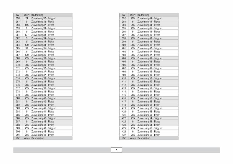
4
CV Wert Bedeutung392 255 Zuweisung44 - Trigger393 0 Zuweisung44 - Flags394 255 Zuweisung44 - Event395 255 Zuweisung45 - Trigger396 0 Zuweisung45 - Flags397 255 Zuweisung45 - Event398 255 Zuweisung46 - Trigger399 0 Zuweisung46 - Flags400 255 Zuweisung46 - Event401 255 Zuweisung47 - Trigger402 0 Zuweisung47 - Flags403 255 Zuweisung47 - Event404 255 Zuweisung48 - Trigger405 0 Zuweisung48 - Flags406 255 Zuweisung48 - Event407 255 Zuweisung49 - Trigger408 0 Zuweisung49 - Flags409 255 Zuweisung49 - Event410 255 Zuweisung50 - Trigger411 0 Zuweisung50 - Flags412 255 Zuweisung50 - Event413 255 Zuweisung51 - Trigger414 0 Zuweisung51 - Flags415 255 Zuweisung51 - Event416 255 Zuweisung52 - Trigger417 0 Zuweisung52 - Flags418 255 Zuweisung52 - Event419 255 Zuweisung53 - Trigger420 0 Zuweisung53 - Flags421 255 Zuweisung53 - Event422 255 Zuweisung54 - Trigger423 0 Zuweisung54 - Flags424 255 Zuweisung54 - Event425 255 Zuweisung55 - Trigger426 0 Zuweisung55 - Flags427 255 Zuweisung55 - EventCV Value Description
CV Wert Bedeutung356 24 Zuweisung32 - Trigger357 0 Zuweisung32 - Flags358 195 Zuweisung32 - Event359 1 Zuweisung33 - Trigger360 0 Zuweisung33 - Flags361 177 Zuweisung33 - Event362 3 Zuweisung34 - Trigger363 0 Zuweisung34 - Flags364 179 Zuweisung34 - Event365 69 Zuweisung35 - Trigger366 0 Zuweisung35 - Flags367 179 Zuweisung35 - Event368 255 Zuweisung36 - Trigger369 0 Zuweisung36 - Flags370 255 Zuweisung36 - Event371 255 Zuweisung37 - Trigger372 0 Zuweisung37 - Flags373 255 Zuweisung37 - Event374 255 Zuweisung38 - Trigger375 0 Zuweisung38 - Flags376 255 Zuweisung38 - Event377 255 Zuweisung39 - Trigger378 0 Zuweisung39 - Flags379 255 Zuweisung39 - Event380 255 Zuweisung40 - Trigger381 0 Zuweisung40 - Flags382 255 Zuweisung40 - Event383 255 Zuweisung41 - Trigger384 0 Zuweisung41 - Flags385 255 Zuweisung41 - Event386 255 Zuweisung42 - Trigger387 0 Zuweisung42 - Flags388 255 Zuweisung42 - Event389 255 Zuweisung43 - Trigger390 0 Zuweisung43 - Flags391 255 Zuweisung43 - EventCV Value Description
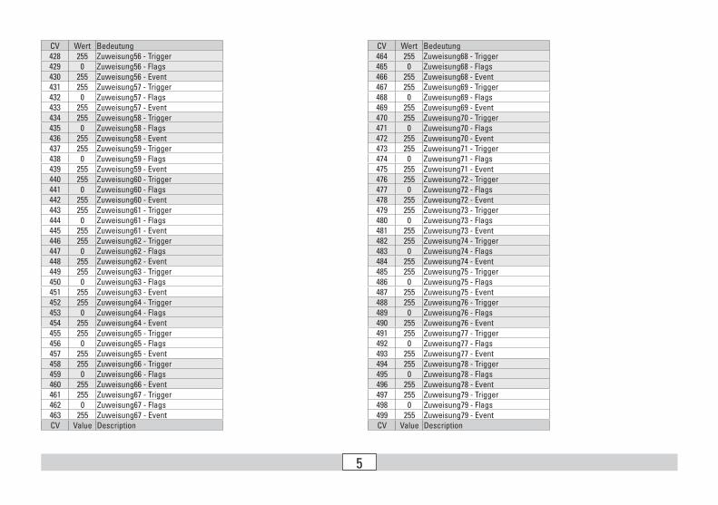
5
CV Wert Bedeutung464 255 Zuweisung68 - Trigger465 0 Zuweisung68 - Flags466 255 Zuweisung68 - Event467 255 Zuweisung69 - Trigger468 0 Zuweisung69 - Flags469 255 Zuweisung69 - Event470 255 Zuweisung70 - Trigger471 0 Zuweisung70 - Flags472 255 Zuweisung70 - Event473 255 Zuweisung71 - Trigger474 0 Zuweisung71 - Flags475 255 Zuweisung71 - Event476 255 Zuweisung72 - Trigger477 0 Zuweisung72 - Flags478 255 Zuweisung72 - Event479 255 Zuweisung73 - Trigger480 0 Zuweisung73 - Flags481 255 Zuweisung73 - Event482 255 Zuweisung74 - Trigger483 0 Zuweisung74 - Flags484 255 Zuweisung74 - Event485 255 Zuweisung75 - Trigger486 0 Zuweisung75 - Flags487 255 Zuweisung75 - Event488 255 Zuweisung76 - Trigger489 0 Zuweisung76 - Flags490 255 Zuweisung76 - Event491 255 Zuweisung77 - Trigger492 0 Zuweisung77 - Flags493 255 Zuweisung77 - Event494 255 Zuweisung78 - Trigger495 0 Zuweisung78 - Flags496 255 Zuweisung78 - Event497 255 Zuweisung79 - Trigger498 0 Zuweisung79 - Flags499 255 Zuweisung79 - EventCV Value Description
CV Wert Bedeutung428 255 Zuweisung56 - Trigger429 0 Zuweisung56 - Flags430 255 Zuweisung56 - Event431 255 Zuweisung57 - Trigger432 0 Zuweisung57 - Flags433 255 Zuweisung57 - Event434 255 Zuweisung58 - Trigger435 0 Zuweisung58 - Flags436 255 Zuweisung58 - Event437 255 Zuweisung59 - Trigger438 0 Zuweisung59 - Flags439 255 Zuweisung59 - Event440 255 Zuweisung60 - Trigger441 0 Zuweisung60 - Flags442 255 Zuweisung60 - Event443 255 Zuweisung61 - Trigger444 0 Zuweisung61 - Flags445 255 Zuweisung61 - Event446 255 Zuweisung62 - Trigger447 0 Zuweisung62 - Flags448 255 Zuweisung62 - Event449 255 Zuweisung63 - Trigger450 0 Zuweisung63 - Flags451 255 Zuweisung63 - Event452 255 Zuweisung64 - Trigger453 0 Zuweisung64 - Flags454 255 Zuweisung64 - Event455 255 Zuweisung65 - Trigger456 0 Zuweisung65 - Flags457 255 Zuweisung65 - Event458 255 Zuweisung66 - Trigger459 0 Zuweisung66 - Flags460 255 Zuweisung66 - Event461 255 Zuweisung67 - Trigger462 0 Zuweisung67 - Flags463 255 Zuweisung67 - EventCV Value Description


![Markus Tiedtke DAS DAMPFLOK-BW in diese Ausgabe...4 Dampflok-Bahnbetriebswerke DAS PERFEKTE BW IM MODELL 7Z^ YZg CVX]W^aYjc\ Z^cZh 7V]cWZig^ZWhlZg`Zh ^b BdYZaa ]Vi bVc Vah 6caV\ZcWVjZg](https://img.pdfslide.org/doc/110x75/60aaa66d1e751d3c7111ddc8/markus-tiedtke-das-dampflok-bw-in-diese-ausgabe-4-dampiok-bahnbetriebswerke.jpg)