Embed Size (px)
Citation preview
PE0112A/PE0112G/PE0212A/PE0212B/PE0212G PDU básica
Unité d'alimentation Basic PDU PE0112A/PE0112G/PE0212A/PE0212B/PE0212G PDU di base PE0112A/PE0112G/PE0212A/PE0212B/PE0212G
PE0112A/PE0112G/PE0212A/PE0212B/PE0212G Basis-PDU Блок питания Basic PE0112A/PE0112G/PE0212A/PE0212B/PE0212G
PE0112A/PE0112G/PE0212A/PE0212B/PE0212G Basic PDU www.aten.com www.aten.com
www.aten.com www.aten.com
www.aten.com www.aten.com
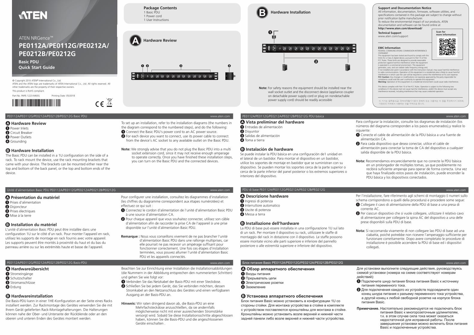
A Hardware Review 1 Power Inlets2 Circuit Breaker3 Power Outlets 4 Grounding
B Hardware InstallationThe Basic PDU can be installed in a 1U confi guration on the side of a rack. To rack mount the device, use the rack mounting brackets that came with your device. The brackets can be mounted either near the top and bottom of the back panel, or the top and bottom ends of the device.
To set up an installation, refer to the installation diagrams (the numbers in the diagram correspond to the numbered steps), and do the following:1 Connect the Basic PDU's power cord to an AC power source.2 For each device you want to connect, use its power cable to connect
from the device's AC socket to any available outlet on the Basic PDU. Note: We strongly advise that you do not plug the Basic PDU into a multi
socket extension cord, since it may not receive enough amperage to operate correctly. Once you have fi nished these installation steps, you can turn on the Basic PDU and the connected devices.
A Hardware Review
B Hardware Installation
© Copyright 2018 ATEN® International Co., Ltd.ATEN and the ATEN logo are trademarks of ATEN International Co., Ltd. All rights reserved. All other trademarks are the property of their respective owners.
This product is RoHS compliant.
Part No. PAPE-1223-M60G Printing Date: 05/2018
Basic PDU Quick Start Guide
PE0112A/PE0112G/PE0212A/PE0212B/PE0212G
ATEN NRGence™
Support and Documentation NoticeAll information, documentation, fi rmware, software utilities, and specifi cations contained in this package are subject to change without prior notifi cation bythe manufacturer. To reduce the environmental impact of our products, ATEN documentation and software can be found online at http://www.aten.com/download/
Technical Supportwww.aten.com/support
이 기기는 업무용(A급) 전자파적합기기로서 판매자 또는 사용자는 이 점을 주의하시기 바라며,
가정외의 지역에서 사용하는 것을 목적으로 합니다.
EMC InformationFEDERAL COMMUNICATIONS COMMISSION INTERFERENCE STATEMENT:This equipment has been tested and found to comply with the limits for a Class A digital device, pursuant to Part 15 of the FCC Rules. These limits are designed to provide reasonable protection against harmful interference when the equipment is operated in a commercial environment. This equipment generates, uses, and can radiate radio frequency energy and, if not installed and used in accordance with the instruction manual, may cause harmful interference to radio communications. Operation of this equipment in a residential area is likely to cause harmful interference in which case the user will be required to correct the interference at his own expense.FCC Caution: Any changes or modifi cations not expressly approved by the party responsible for compliance could void the user's authority to operate this equipment. Warning: Operation of this equipment in a residential environment could cause radio interference.
This device complies with Part 15 of the FCC Rules. Operation is subject to the following two conditions:(1) this device mat not cause harmful interference, and(2) this device must accept any interference received, including interference that may cause undesired operation.
Scan for more information
2
1
31 2 4
Package Contents1 Basic PDU1 Power cord1 User Instructions
Note: For safety reasons the equipment should be installed near the wall socket outlet and the disconnect device (appliance coupler on detachable power supply cord or plug on nondetachable power supply cord) should be readily accessible
A Présentation du matériel 1 Prises d'alimentation2 Disjoncteur3 Prises électriques 4 Mise à la terre
B Installation du matérielL'unité d'alimentation Basic PDU peut être installée dans une confi guration 1U sur le côté d'un rack. Pour monter l'appareil en rack, utilisez les supports de montage en rack fournis avec votre appareil. Les supports peuvent être montés à proximité du haut et du bas du panneau arrière ou sur les extrémités haute et basse de l'appareil.
Pour confi gurer une installation, consultez les diagrammes d'installation (les chiffres du diagramme correspondent aux étapes numérotées) et effectuez ce qui suit :1 Connectez le cordon d'alimentation de l'unité d'alimentation Basic PDU
à une source d'alimentation CA.2 Pour chaque appareil que vous souhaitez connecter, utilisez son câble
d'alimentation afi n de raccorder la prise CA de l'appareil à une prise disponible sur l'unité d'alimentation Basic PDU.
Remarque : Nous vous conseillons vivement de ne pas brancher l'unité
d'alimentation Basic PDU dans une rallonge multiprises, car elle pourrait ne pas recevoir un ampérage suffi sant pour fonctionner correctement. Une fois ces étapes d'installation terminées, vous pouvez allumer l'unité d'alimentation Basic PDU et les appareils connectés.
A Hardwareübersicht 1 Stromeingänge2 Schutzschalter3 Stromanschlüsse 4 Erdung
B HardwareinstallationDie Basis-PDU kann in einer 1HE-Konfi guration an der Seite eines Racks installiert werden. Zur Rackmontage des Gerätes verwenden Sie die mit Ihrem Gerät gelieferten Rack-Montagehalterungen. Die Halterungen können nahe der Ober- und Unterseite der Rückblende oder an den oberen und unteren Enden des Gerätes montiert werden.
Beachten Sie zur Einrichtung einer Installation die Installationsabbildungen (die Nummern in der Abbildung entsprechen den nummerierten Schritten) und gehen Sie wie folgt vor:1 Verbinden Sie das Netzkabel der Basis-PDU mit einer Steckdose.2 Schließen Sie bei jedem Gerät, das Sie verbinden möchten, dessen
Stromkabel an den Netzanschluss des Gerätes und einen verfügbaren Ausgang an der Basis-PDU an.
Hinweis: Wir raten dringend davon ab, die Basis-PDU an eine
Mehrfachsteckdose anzuschließen, da sie andernfalls möglicherweise nicht mit einer ausreichenden Stromstärke versorgt wird. Sobald Sie diese Installationsschritte abgeschlossen haben, können Sie die Basis-PDU und die angeschlossenen Geräte einschalten .
A Vista preliminar del hardware 1 Entradas de alimentación2 Disyuntor3 Salidas de alimentación 4 Toma a tierra
B Instalación de hardwareSe puede instalar la PDU básica en una confi guración de1 unidad en el lateral de un bastidor. Para montar el dispositivo en un bastidor, utilice los soportes de montaje en bastidor que se suministran con su dispositivo. Se pueden montar los soportes cerca de la parte superior o cerca de la parte inferior del panel posterior o los extremos superiores o interiores del dispositivo.
Para confi gurar la instalación, consulte los diagramas de instalación (los números del diagrama corresponden a los pasos enumerados),y realice lo siguiente:1 Conecte el cable de alimentación de la PDU básica a una fuente de
alimentación CA.2 Para cada dispositivo que desea conectar, utilice el cable de
alimentación para conectar la toma de CA del dispositivo a cualquier salida disponible de la PDU básica.
Nota: Recomendamos encarecidamente que no conecte la PDU básica
en un prolongador de múltiples tomas, ya que posiblemente no recibirá sufi ciente amperaje para operar de forma correcta. Una vez que haya fi nalizado estos pasos de instalación, puede encender la PDU básica y los dispositivos conectados.
A Descrizione hardware 1 Ingressi di potenza2 Interruttore automatico3 Uscite di potenza 4 Messa a terra
B Installazione dell'hardwareLa PDU di base può essere installata in una confi gurazione 1U sul lato di un rack. Per montare il dispositivo su rack, utilizzare le staffe di montaggio del rack in dotazione con il dispositivo. Le staffe possono essere montate vicino alle parti superiore e inferiore del pannello posteriore o alle estremità superiore e inferiore del dispositivo.
Per l'installazione, fare riferimento agli schemi di montaggio (i numeri sullo schema corrispondono a quelli della procedura) e procedere some segue:1 Collegare il cavo di alimentazione della PDU di base a una presa di
corrente AC.2 Per ciascun dispositivo che si vuole collegare, utilizzare il relativo cavo
di alimentazione per collegare la spina AC del dispositivo a una delle prese disponibili sulla PDU di base.
Nota: Si raccomanda vivamente di non collegare lao PDU di base ad una
ciabatta, poiché potrebbe non ricevere l’amperaggio suffi ciente per funzionare correttamente. Dopo avere completato le procedure di installazione è possibile accendere la PDU di base ed i dispositivi collegati.
A Обзор аппаратного обеспечения 1 Входы питания2 Прерыватель цепи3 Электрические розетки 4 Заземление
B Установка аппаратного обеспеченияБлок питания Basic можно установить в конфигурации 1U со стороны стойки. Для монтажа устройства в стойке в комплекте с устройством поставляются кронштейны для монтажа в стойке. Кронштейны можно установить возле верхней и нижней части задней панели либо возле верхней и нижней части устройства.
Для установки выполните следующие действия, руководствуясь схемой установки (номера на схеме соответствуют номерам действий):1 Подключите шнур питания блока питания Basic к источнику
питания переменного тока.2 Для подключения каждого из устройств подсоедините один
конец шнура питания к разъему переменного тока устройства, а другой конец к любой свободной розетке на корпусе блока питания Basic.
Примечание. Настоятельно рекомендуется не подключать блок питания Basic к многорозеточным удлинителям, т.к. в этом случае сила тока может оказаться недостаточной для исправной работы. После завершения установки можно включить блок питания Basic и подключенные устройства.
Основний блок PDU PE0112A/PE0112G/PE0212A/PE0212B/PE0212G www.aten.com
PDU Básico PE0112A/PE0112G/PE0212A/PE0212B/PE0212G www.aten.com
PE0112A/PE0112G/PE0212A/PE0212B/PE0212G Temel PDU www.aten.com
www.aten.com
PE0112A/PE0112G/PE0212A/PE0212B/PE0212G ベーシック PDU www.aten.com サポートお問合せ窓口:+81-3-5615-5811
PE0112A/PE0112G/PE0212A/PE0212B/PE0212G Basic PDU www.aten.com Phone: +82-2-467-6789
www.aten.com 电话支持:+86-400-810-0-810
PE0112A/PE0112G/PE0212A/PE0212B/PE0212G 基本型 PDU www.aten.com 技術服務專線:+886-2-8692-6959
A Огляд апаратного забезпечення 1 Вхід живлення2 Автоматичний вимикач3 Виходи живлення 4 Заземлення
B Інсталяція апаратного забезпеченняОсновний PDU може бути встановлено збоку в стійку розміром 1U. Щоб підвісити пристрій на стійку, використовуйте кронштейни для підвішування на стійку, з комплекту поставки пристрою. Монтажні кронштейни можна встановити або зверху і знизу на задній панелі, або на верхній і нижній сторонах пристрою.
Для налаштування інсталяції, перегляньте креслення інсталяції (номери на діаграмі відповідають номерам кроків), виконайте дії, вказані нижче.1 Підключіть шнур живлення основного PDU до джерела живлення
змінного струму.2 Для кожного пистрою, який потрібно підключити, використовуйте
кабель живлення для підключення до розетки змінного струму та будь-якого доступного виходу на основному PDU.
Примітка. Наполегливо рекомендуємо не підключати блок
керування електроживленням основного PDU через подовжувач із кількома розетками, оскільки в них може бути недостатньо струму для правильної роботи. Після виконання кроків встановлення можна ввімкнути блок керування електроживленням основного PDU та підключити пристрої.
A Vista do hardware 1 Entradas de alimentação2 Disjuntor3 Tomadas de alimentação 4 Ligação à terra
B Instalação do hardwareO PDU Básico pode ser instalado numa configuração 1U na parte lateral do bastidor. Para montar o dispositivo no bastidor, utilize os suportes de montagem fornecidos com o dispositivo. Os suportes podem ser montados próximo do topo ou do fundo do painel traseiro ou nas partes superior e inferior do dispositivo.
Para realizar a instalação, consulte os diagramas (os números no diagrama correspondem aos passos numerados) e efetue o seguinte:1 Ligue o cabo de alimentação do PDU Básico a uma fonte de
alimentação AC.2 Para cada dispositivo que deseja ligar, utilize o respetivo cabo de
alimentação para efetuar a ligação desde a tomada AC do dispositivo até uma tomada disponível no PDU Básico.
Nota: Recomendamos vivamente que não ligue o PDU Básico a um cabo
de extensão com múltiplas tomadas, já que poderá não receber corrente suficiente para funcionar corretamente. Quando terminar estes passos de instalação, pode ligar o PDU Básico e os dispositivos conectados.
A Donanıma Bakış 1 Güç Girişleri2 Devre Kesici3 Güç Çıkışları 4 Topraklama
B Donanım KurulumuTemel PDU, bir rafın yan tarafındaki bir 1U yapılandırmasına kurulabilir. Aygıtı rafa kurmak için, aygıtınızla birlikte sağlanan rafa kurulum bağlantı parçalarını kullanın. Bağlantı parçaları ya arka panelin üst ve alt kısımlarının yakınına ya da aygıtın üst ve alt uçlarına kurulabilir.
Bir kurulum yapmak için kurulum şemalarına başvurun (şemadaki sayılar numaralandırılmış adımlara karşılık gelir) ve aşağıdaki işlemleri gerçekleştirin:1 Temel PDU'nun güç kablosunu bir AC güç kaynağına bağlayın.2 Bağlamak istediğiniz her bir aygıtın güç kablosunu, aygıtın AC
yuvasından Temel PDU üzerinde kullanılabilir herhangi bir çıkışa bağlayın.
Not: Doğru şekilde çalışmak için yeterli amper miktarı
alamayabileceğinden, Temel PDU'yu çok yuvalı bir uzatma kablosuna takmamanızı kesinlikle öneririz. Bu kurulum adımlarını tamamladığınızda Temel PDU'yu ve bağlı aygıtları açabilirsiniz.
A Informacje o urządzeniu 1 Wejścia zasilania2 Wyłącznik obwodu3 Wyjścia zasilania 4 Uziemienie
B Instalacja urządzeniaPodstawową jednostkę PDU można zainstalować w konfiguracji 1U z boku szafy. Do montażu urządzenia w szafie należy użyć wsporników do montażu w szafie dołączonych do urządzenia. Wsporniki można zamocować przy górnej i dolnej krawędzi panelu tylnego lub przy górnym i dolnym końcu urządzenia.
W celu instalacji należy zapoznać się ze schematem instalacji (cyfry na schemacie odpowiadają kolejnym krokom), a następnie należy wykonać poniższe czynności:1 Podłącz przewód zasilający podstawowej jednostki PDU do źródła
zasilania AC.2 W przypadku każdego urządzenia należy podłączyć jego kabel
zasilający do gniazda AC urządzenia i do dowolnego dostępnego gniazda elektrycznego podstawowej jednostki PDU.
Uwaga: Zdecydowanie nie zaleca się podłączania podstawowej
jednostki PDU do wielogniazdowego przedłużacza, ponieważ natężenie prądu mogłoby być niewystarczające do zapewnienia prawidłowego działania urządzenia. Po wykonaniu czynności instalacyjnych można włączyć podstawową jednostkę PDU i podłączone urządzenia.
A 製品各部名称 1 AC インレット2 回路ブレーカー3 電源アウトレット 4 接地
B ハードウェアのセットアップベーシックPDU は、ラックの側面に1U 構成で取り付けることができます。 デバイスをラックマウントするには、デバイスに同梱されているラックマウント用ブラケットを使用してください。ブラケットはリアパネルの上面または底面、またはデバイスの上端および下端に取り付けることができます。
セットアップする場合は、上記のセットアップ図を参照してください。( 図内における番号は下記の作業手順に対応 )1 ベーシック PDU の電源ケーブルを AC 電源に接続してください。2 接続するデバイスごとに、電源ケーブルを使用して、ベーシック PDU の利
用可能なソケットのいずれかに、デバイスの AC ソケットを接続してください。
注意: 正常な動作を行うために十分なアンペア数が得られない可能性があ
りますので、マルチソケット延長コードへのベーシック PDU 接続は推奨しません。これらのセットアップ手順を完了後、ベーシック PDUと接続されたデバイスの電源を入れることができます。
A 하드웨어 리뷰 1 전원 입력부2 회로 차단기3 전원 출력부 4 접지
B 하드웨어 설치Basic PDU 는 랙 측면의 1U 구성에 설치할 수 있습니다 . 장치를 랙에 장착하려면 장치와 함께 제공된 랙 장착 브래킷을 사용하십시오 . 브래킷은 후면 패널의 상부와 하부 또는 장치의 상단 및 하단에 장착할 수 있습니다 .
설치하려면 설치도 ( 그림의 번호는 같은 번호가 매겨진 단계에 해당함 ) 를 참조하여 다음을 수행하십시오 .1 Basic PDU 의 전원 코드를 AC 전원에 연결합니다 .2 연결하려는 각 장치마다 전원 케이블을 사용하여 장치의 AC 소켓과
Basic PDU 에서 사용 가능한 출력부를 연결하십시오 . 주의 : 장치가 제대로 작동하는 데 충분한 전류를 공급받지 못할 수
있으므로 Basic PDU 를 멀티소켓 연장 코드에 연결하지 않는 것이 좋습니다 . 위의 설치 단계를 마치면 Basic PDU 와 연결된 장치를 켤 수 있습니다 .
A 硬件概览 1 电源插口(电源输入口)2 断路器3 电源插座(电源输出口) 4 接地
B 硬件安装基本 PDU 可以按照 1U 配置安装在机架侧面。如要将设备安装在机架上,请使用设备附带的机架安装支架。支架既可以安装在后面板的顶部和底部附近,也可以安装在设备的顶端和底端。
设置安装时,请参照安装图(图中的数字对应于步骤编号),执行下列操作:1 将基本 PDU 的电源线连接到交流电源。2 对于要连接的每个设备,使用其电源线将设备的交流插口连接到基本
PDU 上的任何可用插座。 注意:我们强烈建议您不要将基本 PDU 插入多插座接线板,因为它可能
无法获得正常运行所需的足够电流。完成这些安装步骤后,即可开启基本 PDU 和所连接的设备。
A 硬體檢視1 電源插口2 斷路器3 電源插座 4 接地
B 硬體安裝基本型 PDU 可以按照 1U 配置安裝在機架側面。要將設備安裝在機架上,請使用設備附帶的機架安裝支架。支架既可以安裝在後面板的頂部和底部附近,也可以安裝在設備的頂端及底端。
設備安裝時,請參照安裝圖(圖中的數字對應於步驟編號),執行下列操作:1 將基本型 PDU 的電源線連接到 AC 電源。2 對於要連接的每個設備,使用其電源線將設備的 AC 插座連接到基本
型 PDU 上的可用插座。 注意:我們強烈建議您不要將基本型 PDU 插入多插座延長線,因為它可
能無法獲得正常運行所需的足夠電流。完成這些安裝步驟後,即可開啟基本型 PDU 和所連接的設備。
PE0112A/PE0112G/PE0212A/PE0212B/PE0212G 基本 PDU
Podstawowa jednostka PDU PE0112A/PE0112G/PE0212A/PE0212B/PE0212G