Embed Size (px)
Citation preview

Performance Evaluation of IVC Systems - Part 1: Test Instructions -
M. Scheer1, C. Heinekamp2, B. Thull3, R. Wagner4 & H.-P. Scheuber5 1TECNIPLAST Deutschland GmbH, Hettenstr. 18, 82383 Hohenpeißenberg, Ger-many, 2dr. heinekamp Labor- und Institutsplanung GmbH, Gaußstr. 12, 85757 Karlsfeld, Germany, 3TÜV Süddeutschland, Westendstr. 199, 80686 München, Ger-many, 4LTG-Aktiengesellschaft, Grenzstr. 7, 70435 Stuttgart, Germany, 5Tier-schutzInformationsZentrum für die Biomedizinische Forschung (TIZ-BIFO) der Medizinischen Fakultät, Department of Clinical Biochemistry in the Surgical Clinic, Klinikum Innenstadt, Ludwig-Maximilians-Universität (LMU) München, Nußbaumstr. 20, 80336 Munich, Germany Members of the working group of the IVC industry / engineers: M. Scheer (Sprecher), TECNIPLAST Deutschland GmbH, Hohenpeißenberg (D) und Ch. Heinekamp (Sprecher), dr.heinekamp Labor- und Institutsplanung GmbH Karls-feld (D); A. Brunink, PLEXX, PW-Elst (NL); J. Camphuis, UNO ROESTVASTAAL BV, AA Zevenaar (NL); D. Clark, BioZone Inc. North American Headquaters, Fort Mill (USA); M. Jung, PLEXX-EMSICON JUNG GMBH, Forstinning (D); P. Leonhardt, SCANBUR AS, Koge (DK); J. MacArthur Clark, BioZone Ltd. European Head Office, Margate (UK); I.M. Müller, dr. heinekamp Labor- und Institutsplanung GmbH Berlin (D); P. Oehlert, EHRET GmbH & Co. KG, Emmendingen (D); H. Rittlinger, MBS-Haltungssysteme Hockenheim (D); B. Thull, TÜV Süddeutschland, Munich (D); H. Untiedt, E. Becker & Co. GmbH, Castrop-Rauxel (D) and R. Wagner, LTG-Aktien-gesellschaft, Stuttgart (D).

Performance Evaluation of IVC Systems Part 1: Test Instructions
2
CONTENTS Page 1. Introduction 3 2. Scope of Application and Purpose 4 3. Terms and Definitions 5 4. Description of Ventilation System 8 4.1 Cage Ventilation Parameters 8 4.1.1 Laboratory Test Cage 8 4.1.2 Airflow Velocity 9 4.1.2.1 Setup of Measuring Instruments and Methods 9 4.1.2.2 Measurement Evaluation and Limiting Values 10 4.1.3 Differential Pressure 10 4.1.3.1 Setup of Measuring Instruments and Methods 11 4.1.3.2 Measurement Evaluation and Limiting Values 11 4.1.4 Local Air Exchange Rate 11 4.1.4.1 Setup of Measuring Instruments and Methods 11 4.1.4.2 Measurement Evaluation and Limiting Values 12 4.1.5 Short-circuit Airflow 12 4.1.5.1 Setup of Measuring Instruments and Methods 12 4.1.5.2 Measurement Evaluation and Limiting Values 13 4.1.6 Inleakage 13 4.1.6.1 Setup of Measuring Instruments and Methods 13 4.1.6.2 Measurement Evaluation and Limiting Values 14 4.2 Cage-Rack Ventilation Parameters 14 4.2.1 Measuring Cage 14 4.2.2 Distribution of Pressure Differentials over Cage-rack 15 4.2.2.1 Setup of Measuring Instruments and Methods 15 4.2.2.2 Measurement Evaluation and Limiting Values 16 4.2.3 Distribution of Air Exchange Rates over Cage-rack 16 4.2.3.1 Setup of Measuring Instruments and Methods 16 4.2.3.2 Measurement Evaluation and Limiting Values 17 4.2.4 Inleakage of Cage-Rack 17 4.2.4.1 Setup of Measuring Instruments and Methods 17 4.2.4.2 Measurement Evaluation and Limiting Values 18 4.2.5 Secondary Airflow 18 4.2.5.1 Setup of Measuring Instruments and Methods 18 4.2.5.2 Measurement Evaluation and Limiting Values 18

Performance Evaluation of IVC Systems Part 1: Test Instructions
3
5. Climatic Parameters: Air Temperature and Humidity 19 6. Filter Systems Specifications 19 7. Acoustics Parameters 19 7.1 Noise 19 7.1.1 Setup of Measuring Instruments and Methods 19 7.1.2 Measurement Evaluation and Limiting Values 21 7.2 Solide-borne Noise 21 7.2.1 Setup of Measuring Instruments and Methods 21 7.2.2 Measurement Evaluation and Limiting Values 22 8. Error Messages 22 Appendix A: Standards and Publications 22 Appendix B: Acoustics-related Considerations for the Combined
System "Ventilation Unit – Cage-rack" 24
1. Introduction The introduction of IVC systems has brought a new kind of complex technical equip-ment into the animal rooms of animal laboratories. The evaluation of the technology employed and offered by these systems is decisive for animal care conditions. How-ever, a standardized overview and evaluation of all the technical implications has not been available. Against this background, the animal protection center for biomedical research of the Faculty of Medicine (TierschutzInformationsZentrum für die Biomedizinische For-schung der Medizinischen Fakultät, TIZ-BIFO), a working group of the Ludwig-Maximilian-University of Munich, started an initiative in the Autumn of 2000 to draw up a criteria catalog for the establishment of environmental and ventilation parame-ters for ventilated cage systems. For this purpose, users, planners, manufacturing companies and test institutions as well as members of laboratory animal associations throughout Europe were invited to participate in this undertaking. Since then, these experts have been working on establishing the requisite parame-ters and measuring methods in the course of specialist discussions and subject-related workgroups. The goal of these efforts was to investigate and determine the factors influencing the welfare of the animals without using laboratory animals to do so. The technical findings resulting from these investigations can be used as a basis for further physiological research on animals.

Performance Evaluation of IVC Systems Part 1: Test Instructions
4
2. Scope of Application and Purpose These test instructions apply to forced-ventilation cage systems such as are used in laboratory research involving animals, especially for the care and use of mice and rats. They apply to systems operating with positive and negative pressure. These instructions do not apply to open cage systems, to cages in isolators or to ventilated cabinets. The purpose of these test instructions is to define testing parameters and methods to establish and evaluate ventilation, climatic and acoustic factors as well as error messages. In this way, quality standards for IVC systems can be specified and com-pliance with these standards can be objectively monitored. Note: On completion of these test instructions it was known that the majority of all IVC systems used are operated with a decentralized air supply system, i.e. ventilation units installed on the cage-racks to control the air supply and exhaust extraction of the cages. Only in very few cases this function is carried out by a centralized air sup-ply & exhaust system. Nevertheless, it was decided to locate the interface at the fit-ting of the cage-rack for the following reasons: 1. For the air supply of the animals, it must be irrelevant how air is supplied to
and exhausted from the cages. 2. The complexity of the ventilation systems as well as the number of possible
installation configurations would by far exceed the scope of these instructions, both in time and content.
Reference: In a second part there is a list of user aspects with categorical questions for the evaluation of IVC systems by means of technical determinations (i.e. handling, service, hygienic aspects, etc.), that are in terms of quantity not (or only hard) to describe. This part 2 has the title "Evaluation Criteria" and composes together with the present part 1 ("Test Instructions") the "Performance Evaluation of IVC Systems".

Performance Evaluation of IVC Systems Part 1: Test Instructions
5
3. Terms and Definitions Acoustic test cage: This is a standard cage in which holes have been drilled in the front panel to allow the insertion of microphones and triaxial acceleration sensors to measure, for in-stance in a testing laboratory, the acoustic and oscillation characteristics. This can be carried out at different positions of this cage within the rack. Air exchange rate, expressed as ACH (Air Changes per Hour): The air exchange rate indicates how often the air – e.g. in a cage – is exchanged. The unit of measurement is 1/h. IVC systems are often operated with an ACH of 30 to 90 1/h. Unless stated otherwise, ACH is taken to mean the exchange of air occur-ring when the air uniformly passing the entire volume of the cage. An exception to this is the local ACH; in this case, the ACH at a specific location within the cage is meant. Where the airflow within the cage is performed uniformly, the values of these two different ACH types will not differ substantially from each other. Airflow velocity: The velocity at which a fluid (e.g. a liquid or gas) flows. Bedding: Material (mostly based on wood shavings) spread on the floor of the cages (about 2 cm deep) so that the animals are not sitting on the bare plastic floor. Cage hood: Serves to seal the cages. Without such a hood, the cages would be “open cages”, which do not offer protection at cage level (see IVCs). Centralized / decentralized ventilation: In centralized ventilation systems, there are no ventilation units installed inside the animal rooms. The cage-racks are connected directly to the building’s central air supply and exhaust lines via fixed connection ducts or boxes. In decentralized venti-lation systems, ventilation units that supply the cage-racks with air or extract the ex-haust from the cages are installed inside the animal rooms. Instead of into the room itself, this exhaust air can alternatively be extracted directly into the central exhaust system. Cross contamination: Cross contamination is the infiltration or transfer of microbes or similar micro-organisms from one microbiological unit to another; for instance, the transfer of microbes from one (single) cage to another. Differential pressure: In the following this usually refers to the differential pressure
�pR-C. In the context
given, the difference between the pressure in the interior of the cage and the pres-sure of the room is meant. This ratio is usually expressed in Pa (Pascal).

Performance Evaluation of IVC Systems Part 1: Test Instructions
6
Drinking bottle: Bottle usually made of plastic with a filling volume of 200 to 1000 ml from which drinking liquids are provided to the animals in the cages. Error message: Message given by the system in the case of an error (deviation of the actual value from the set value). Qualified error messages also provide the operator with addi-tional information on the type of fault, for instance, whether the fault has been caused by electricity supply failure or by a functional malfunction in the system. The alarm message can be displayed on site or can be transmitted by means of potential-free contacts to a central control station. Filter systems: All the filters used in a system. These can be preliminary filters and HEPA filters (High Efficiency Particle Arrestance) that are used in the ventilation units, or micro-filters that filter the air on cage level when entering or being extracted from the cages. Hot-wire anemometer: A measuring instrument commonly used to measure air velocity. An electrical current passes through an exposed fine wire, so causing a heating up. If the wire is cooled by air flow the heat dropp causes the electrical resistance to change. The signal resulting from this resistance change can be converted into (a change in) airflow velocity. Inleakage: The (quantity of) air that escapes from openings or between the cage base and cage hood (in the case of positive pressure), or air that flows into the cage (in the case of negative pressure). Inleakage is not the same as false airflow; however, it is a characteristic parameter for how leak-proof / airtight the unit "base−hood−rack" is. IVC (Individually Ventilated Cage): IVCs are cage systems with forced ventilation that offer hygienic / allergy protection of animals, humans and the environment at cage level. This is achieved by sealing the cage with a cage hood. To ensure that the animals in this sealed unit are supplied with air, a ventilation system is required to feed air into the cage, extract exhaust air and maintain the airflow within the cage. IVC cage-rack: Rack for stacking IVC units (in rows and columns); usually on runners and made of stainless steel. The cage-rack is the connecting link between the IVC cages and the ventilation system. Laboratory test cage: This is a cage where holes have been drilled into the side panels to allow the in-sertion of measuring sensors to determine, for instance in a testing laboratory, the air velocity or the local ACH at various locations within the cage. Local air exchange rate: See air exchange rate.

Performance Evaluation of IVC Systems Part 1: Test Instructions
7
Measuring cage: The measuring cage is used to measure the homogeneity of the air distribution within an IVC rack. For this pupose, it is fitted with the requisite measuring and display ele-ments. Positive / negative pressure: Positive and negative pressure are the operating modes in which IVCs are run. Negative pressure means that the air pressure in the cage is lower than the pressure in the ambient atmosphere, i.e. that air migrates from the room outside into the cage and, consequently, that no air can escape from the cage into the ambient room. The objective is to protect users and the environment, for instance, from germs of infected animals (emission protection). In positive pressure mode, it is the other way around: By relatively higher pressure inside the cage air escapes from the cage interior to the room outside. The aim of this mode is to protect the animals (immission protection). Secondary airflow: Uncontrolled or undesired airflow, from a technical and hygienic point of view; for in-stance, airflow causing cross contamination between the individual cages in a rack or the inflow of unfiltered air into the cages in the case of positive pressure. Short-circuit airflow rate: Air rate that flows in the cage directly from the air supply inlet to the exhaust outlet without having passed the area where the animals are. Single cage: Here, a cage is considered as a single unit. In contrast to this, sometimes all the cages in one rack may be considered as one unit. Smoke tube test: Optical test method used to visualize and evaluate air movement by observing aero-sols. The smoke is generated by means of a smoke tube or similar device. Technical acoustics: In this case: technology used to measure and evaluate the noise levels that the ani-mals are exposed to. Tracer gas analysis: An investigative method in which a room is filled with a special gas, the so-called tracer gas. Then the rate at which the gas diminishes is measured. Conclusions re-lating to the ACH can be drawn from the findings.

Performance Evaluation of IVC Systems Part 1: Test Instructions
8
4. Description of Ventilation System In the following, the technical ventilation parameters for the entire system are described, whereby a differentiation is made between the parameters for the (single) cage (4.1) and the parameters for the cage-rack (4.2). 4.1 Cage Ventilation Parameters This section describes the air conditions in a single cage. The interfaces to the cage-rack are defined as the inflow und outflow openings / valves. 4.1.1 Laboratory Test Cage In order to determine the air conditions within a cage comparatively and unequivo-cally, a special laboratory test cage of this cage type is necessary. This cage is basi-cally a standard cage. By drilling holes into the cage panels, it is possible to insert measuring sensors. These measuring sensors can read signals at various locations within the test cage. The position of the 5 measuring points per measuring level is defined as follows:
Side view
50 mm
1/6
1/6
1/6
1/6
1/3
1/3
1/3 1/3
Top view
(150 mm)
Notes on borehole positioning / shaping: 1. Three holes (on one level) are drilled into a side panel of the cage through which
the measuring sensors are passed horizontally so that they can pick up the measurement signals at the intersection points (see top view).
2. To avoid misrepresentation of the actual conditions, the holes must be drilled in such a way that no air can flow between the measuring sensors and the holes. When measurements are being carried out at one hole, all the other holes must be sealed.
3. Measuring points that are covered by the food hopper or the drinking bottle holder are not valid. Where this is the case, it must be recorded in the measurement protocol.
4. When cage bases exceed a height of 180 mm, measurements must be carried out on a third level (150 mm); in cages with a lower height, two measuring levels are sufficient (at 50 mm and 100 mm).
5. Measurements should be performed with the drinking bottle installed in the holder. If this is not feasible, it must be recorded in the measurement protocol.
Performance Evaluation of IVC Systems Part 1: Test Instructions
9
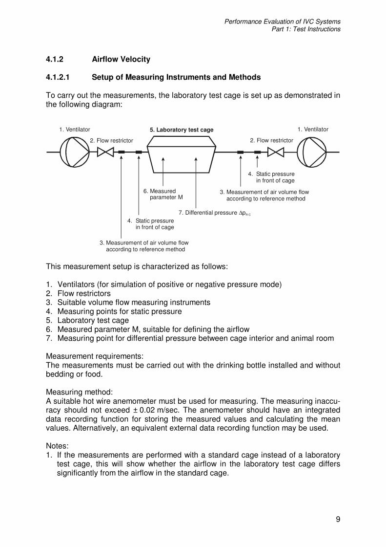
4.1.2 Airflow Velocity 4.1.2.1 Setup of Measuring Instruments and Methods To carry out the measurements, the laboratory test cage is set up as demonstrated in the following diagram:
2. Flow restrictor 2. Flow restrictor
5. Laboratory test cage1. Ventilator 1. Ventilator
3. Measurement of air volume flow according to reference method
3. Measurement of air volume flow according to reference method
4. Static pressure in front of cage
4. Static pressure in front of cage
7. Differential pressure p∆ R-C
6. Measured parameter M
This measurement setup is characterized as follows: 1. Ventilators (for simulation of positive or negative pressure mode) 2. Flow restrictors 3. Suitable volume flow measuring instruments 4. Measuring points for static pressure 5. Laboratory test cage 6. Measured parameter M, suitable for defining the airflow 7. Measuring point for differential pressure between cage interior and animal room Measurement requirements: The measurements must be carried out with the drinking bottle installed and without bedding or food. Measuring method: A suitable hot wire anemometer must be used for measuring. The measuring inaccu-racy should not exceed ± 0.02 m/sec. The anemometer should have an integrated data recording function for storing the measured values and calculating the mean values. Alternatively, an equivalent external data recording function may be used. Notes: 1. If the measurements are performed with a standard cage instead of a laboratory
test cage, this will show whether the airflow in the laboratory test cage differs significantly from the airflow in the standard cage.

Performance Evaluation of IVC Systems Part 1: Test Instructions
10
2. Depending on the purpose of the measurements carried out, it can be of decisive importance whether the test cage in the measurement setup is connected in such a way that no leakage at all is possible at the connecting points, or whether the cage is connected as in every-day practice. For this reason, it must always be specifically stated whether the test cage connection was “completely leak-proof” or installed “as under normal operating conditions”.
4.1.2.2 Measurement Evaluation and Limiting Values As many of the different IVC systems presently on the market utilize different prin-ciples of airflow, there are no generally applicable ACH values specifying the air velocity at which the measurements should be carried out. It is, therefore, recom-mended to proceed as follows: Every manufacturer of IVC systems shall state the ACH range (minimal – middle – maximal) recommended for operation of his system. Subsequently, measurements for three ACH values shall be carried out: - for the minimal ACH range, - for the middle ACH range, - for the maximal ACH range. The evaluation (preferably presented in tabular form) has to show the air velocities for the three ACH values (minimal – middle – maximal) at the various measuring points. The upper limiting value of air velocity is usually defined as the range exceeding 0.2 m/s, which is commonly perceived by the human as a draft. For this reason, at every measuring point on every measuring level, a velocity of 0.2 m/s should not be exceeded. The evaluation must be complemented by an appropriate error analysis. 4.1.3 Differential Pressure The air quantities (respective ACH), the airtightness of the cage and the differential pressure differentials between the cage interior and the room outside the cage repre-sent a triple-value set, where determination of the first two values usually determines the third value. In contrast to the ACH which, as a variable parameter, can be directly increased or decreased linearly by alteration of the air quantities, the differential pressure between the cage interior and the animal room is usually the result of the ACH that has been set and the airtightness of the cage. In other words, the differential pressure is (in most cases) not set as a primary target value in order to read the resulting ACH, but rather the opposite procedure is followed, in which the air quantities are set by regu-

Performance Evaluation of IVC Systems Part 1: Test Instructions
11
lating the air supply and exhaust until the required ACH is achieved as well as the desired pressure conditions. It is, therefore, important for a correct understanding of the methods described under 4.1.3.1 and 4.1.3.2, to observe the close relationship with point 4.1.2. 4.1.3.1 Setup of Measuring Instruments and Methods The measurement setup is identical to the setup described under 4.1.2. The measurement of the differential pressure is also illustrated under this point (in the diagram under no. 7). The position of the measuring point in the cage is irrelevant for the measurement, as no (measurable) pressure gradients occur inside the cage. However, it must be en-sured that only the static pressure is measured and that no dynamic components (“impact pressure") are included. An appropriate measurement method should be used, for instance a piezoelectric transducer. The measurement inaccuracy should be lower than 5% of the maximum pressure and must not exceed 2 Pa. 4.1.3.2 Measurement Evaluation and Limiting Values The differential pressure values must be determined for all (ACH) cases in which the air velocity is measured. The evaluation might also be documented in the air velocity table (see 4.1.2.2). It is expected that the differential pressure range between –40 Pa and +40 Pa. The evaluation must be complemented by an appropriate error analysis. 4.1.4 Local Air Exchange Rate 4.1.4.1 Setup of Measuring Instruments and Methods The measurement of the local ACH rate is carried out in a test cage at the 5 measur-ing points on the lower measuring level (measuring level and points correspond to those under 4.1.1). Measurement requirements: The measurements must be carried out with the drinking bottle installed and without bedding or food. Measurements are performed for both operating modes (positive and negative pressure) with the three ACH rates stated by the cage manufacturer (see 4.1.2.2). At the same time, the differential pressure is determined according to 4.1.3.

Performance Evaluation of IVC Systems Part 1: Test Instructions
12
Measuring method: To set the ACH to the rates given by the manufacturer, a calibrated gasometer or an equivalent measuring method must be used. To determine the local ACH rate, the concentration-decay method using a tracer gas must be applied. In this method, a tracer gas (such as N2O) is injected into the cage and the abating concentration is measured over time at the individual measuring points. This measurement must be repeated three times. 4.1.4.2 Measurement Evaluation and Limiting Values In the case of an ideal mixture of the tracer gas with the air inside the cage, the volumetric content of the tracer gas decreases according to the following equation:
ntttt e −
== *0
σσ (1) The ACH value n can then be calculated using the two measured values according to the equation of:
2
1ln*1
12 tt
tt
ttn
=
=
−=
σσ
(2)
n ACH rate in h-1 t Time when tracer gas sample was taken �
t=t0 Initial volumetric content of tracer gas at time of t0 (start of injection) �t=t1 Volumetric content of tracer gas at time of t1 �t=t2 Volumetric content of tracer gas at time of t2
Subsequent to an appropriate conversion of the equation (1) (logarithmic calculus), the mean ACH value n can be determined by means of a compensation calculation (linear regression) as the slope of the straight line of regression. This calculation can, for instance, be carried out using a spreadsheet program. Uo to now no recommendable limiting values have been established for a permis-sible dispersion of the local ACH rates. Therefore the standard deviation has to be indicated. The evaluation must be complemented by an appropriate error analysis. 4.1.5 Short-circuit Airflow 4.1.5.1 Setup of Measuring Instruments and Methods The proportion of short-circuit airflow is measured immediately behind the air exit point using the tracer gas method. Measurement requirements and methods: see 4.1.4.1.
Performance Evaluation of IVC Systems Part 1: Test Instructions
13
4.1.5.2 Measurement Evaluation and Limiting Values The proportion of short-circuit airflow is determined by analyzing the graph of the abating concentration. Evaluation of the graph is carried out as described under 4.1.4.2. The highest permissible short-circuit airflow proportion is 10%. The evaluation must be complemented by an appropriate error analysis. 4.1.6 Inleakage 4.1.6.1 Setup of Measuring Instruments and Methods The inleakage rate can be defined as follows:
volumeairsupply(entering)volumeinleakagelintentiona
pressurepositiveofcaseIn :
Positive pressure: Intentional inleakage volume = supply volume minus exhaust volume
volumeairexhaust(leaving)volumeinleakagelintentiona
pressurenegativeofcaseIn :
Negative pressure: Intentional inleakage volume = exhaust volume minus supply volume The inleakage can be determined by a comparison of supply and exhaust air vol-umes. The test is carried out with 10 cages taken from current production. Measurement requirements: To achieve the same conditions as in the cage-rack, the cages must be installed in a single cage slot under the same conditions as in the cage-rack (guide runners, hold-ing brackets, air supply and extraction connections, holding pressure on seals etc.) so that the same level of airtightness / leakage as in the cage-rack is ensured at the connecting points. Setup of measuring instruments: see diagram in 4.1.2.1. Further measurement requirements: see 4.1.4.1.
Performance Evaluation of IVC Systems Part 1: Test Instructions
14
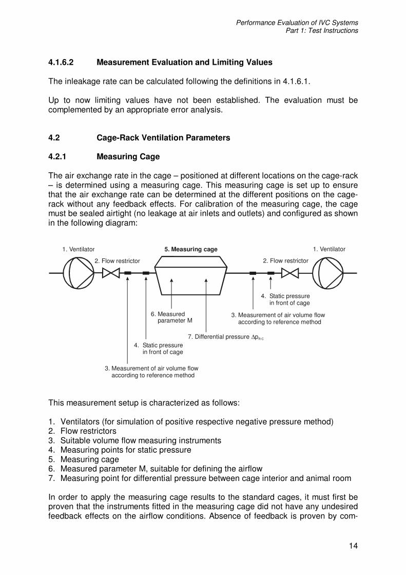
4.1.6.2 Measurement Evaluation and Limiting Values The inleakage rate can be calculated following the definitions in 4.1.6.1. Up to now limiting values have not been established. The evaluation must be complemented by an appropriate error analysis. 4.2 Cage-Rack Ventilation Parameters 4.2.1 Measuring Cage The air exchange rate in the cage – positioned at different locations on the cage-rack – is determined using a measuring cage. This measuring cage is set up to ensure that the air exchange rate can be determined at the different positions on the cage-rack without any feedback effects. For calibration of the measuring cage, the cage must be sealed airtight (no leakage at air inlets and outlets) and configured as shown in the following diagram:
2. Flow restrictor 2. Flow restrictor
5. Measuring cage1. Ventilator 1. Ventilator
3. Measurement of air volume flow according to reference method
3. Measurement of air volume flow according to reference method
4. Static pressure in front of cage
4. Static pressure in front of cage
7. Differential pressure p∆ R-C
6. Measured parameter M
This measurement setup is characterized as follows: 1. Ventilators (for simulation of positive respective negative pressure method) 2. Flow restrictors 3. Suitable volume flow measuring instruments 4. Measuring points for static pressure 5. Measuring cage 6. Measured parameter M, suitable for defining the airflow 7. Measuring point for differential pressure between cage interior and animal room In order to apply the measuring cage results to the standard cages, it must first be proven that the instruments fitted in the measuring cage did not have any undesired feedback effects on the airflow conditions. Absence of feedback is proven by com-
Performance Evaluation of IVC Systems Part 1: Test Instructions
15
parison of the static pressures in the measuring cage and the standard cages. Calibration is carried out in both operating modes (positive and negative pressure) at an ACH rate of 0.5 times the minimum ACH to 1.5 times the maximum ACH rate (according to the manufacturer recommendations, see 4.1.2.2). For each operating mode measured, a calibration function (formula, graph, table) must be specified. Note: If measuring cages are used in laboratory animal care facilities to evaluate air con-ditions in cage-racks, it must be taken into consideration that measuring cages – in contrast to cages with animals inside – will maintain their airtightness constantly, as they are not subject to changes caused by external influences like washing, auto-claving and use. 4.2.2 Distribution of Differential Pressure over Cage-Rack 4.2.2.1 Setup of Measuring Instruments and Methods The differential pressure between cage and room is usually measured via the opening for the drinking bottle. Normally, a standard drinking bottle with an opening on the bottom of the bottle and a fitting for a flexible tube is used. The tube is con-nected to the pressure-measuring instrument. As an alternative, a device that simu-lates the drinking bottle may also be used. The pressure-measuring instrument must be inserted through the opening into the cages at each cage location of a completely filled cage-rack, and the differential pressure measured in the cages must be docu-mented. If a cage system without an opening for an external bottle is used, then a standard cage with a fitting for a flexible tube must be used for connecting the pressure-measuring instrument. This cage is slotted into every single cage position of an otherwise full rack. However, it must be noted, that – using this measuring method – the dispersion of cage manufacturing tolerances is not taken into account. The influence of empty cage positions in the rack must also be documented. For this purpose, the manufacturer must state the number of cages that can be simul-taneously removed vertically and/or horizontally. For partially empty racks, the differential pressure distribution must then be documented. Measurement requirements: The measurements must be carried out without bedding and food. Measurements are performed for both operating modes (positive and negative pressure) with the three ACH rates stated by the cage manufacturer (see 4.1.2.2). Measuring method: Measurements are usually carried out with a piezoelectric transducer. The measure-ment inaccuracy should be lower than 5% of the maximum differential pressure and must not exceed 2 Pa.

Performance Evaluation of IVC Systems Part 1: Test Instructions
16
4.2.2.2 Measurement Evaluation and Limiting Values For evaluation purposes, the following homogeneity specification applies: The absolute amount of the mean value of ∆pR-C must be greater than 1.2 x the absolute amount of the difference of ∆pR-C max. – ∆pR-C min., i.e.:
minmax*2,1 CRCRCR ppp
mean −−− ∆−∆≥∆
The following limiting values apply: Positive pressure range ∆pR-C mean < 40 Pa Negative pressure range ∆pR-C mean > - 40 Pa The evaluation also includes an appropriate comparison of the measured values of the full rack with the partially empty rack. For this purpose, the following must be observed: Measurements carried out with drinking bottles (or similar) return results in which the dispersion includes both: the leakage of the single cages and the divergence of the pressure distribution over the cage-rack. In contrast to this, measurements with the above-mentioned cage only deliver a result for the non-homogeneity of pressure distribution in the cage-rack. The evaluation must be complemented by an appropriate error analysis. 4.2.3 Distribution of Air Exchange Rates over Cage-rack 4.2.3.1 Setup of Measuring Instruments and Methods In order to measure the distribution of the air exchange rate over the cage-rack, a measuring cage is calibrated according to 4.2.1. In a full cage-rack, for each cage position a standard cage is exchanged for this measuring cage and the air exchange rate is measured. Measurement requirements: The measurements must be carried out without bedding and food. Measurements are performed for both operating modes (positive and negative pressure) with the three ACH rates stated by the cage manufacturer (see 4.1.2.2). Measuring method: Measurement is performed using a method without feedback effects (see 4.2.1).

Performance Evaluation of IVC Systems Part 1: Test Instructions
17
4.2.3.2 Measurement Evaluation and Limiting Values The lowest ACH value must be greater than 0.85 x ACH mean value.
meanACHACH *85,0min > The highest ACH value must be less than 1.15 x ACH mean value.
meanACHACH *15,1max < Evaluation must show (preferably in tabular form) the ACH values for the different positions of the cages. The evaluation must be complemented by an appropriate error analysis. 4.2.4 Inleakage of Cage-Rack 4.2.4.1 Setup of Measuring Instruments and Methods In conformity with the specifications for single cages (see 4.1.6.1), the inleakage rates for cage-racks are defined as follows:
volumeairsupply(entering)volumeinleakagelintentiona
pressurepositiveofcaseIn :
Positive pressure: Intentional inleakage volume = supply volume minus exhaust volume
volumeairexhaust(leaving)volumeinleakagelintentiona
pressurenegativeofcaseIn :
Negative pressure: Intentional inleakage volume = exhaust volume minus supply volume Analogous to the measurement setup in 4.1.2.1, a cage-rack filled with cages from current production is connected, both on the air supply as well as on the air exhaust, to a ventilator with a flow restrictor and a suitable volume flow measuring device. The connections to the cage-rack should be airtight, i.e. preventing any possibility of secondary airflow. Measurement requirements: The measurements must be carried out without bedding and food. Measurements are performed for both operating modes (positive and negative pressure) with the three ACH rates stated by the cage manufacturer (see 4.1.2.2).

Performance Evaluation of IVC Systems Part 1: Test Instructions
18
Measuring method: Measurement is carried out analogously to 4.1.2.1. However, instead of the labora-tory test cage, the cage-rack is used. 4.2.4.2 Measurement Evaluation and Limiting Values The inleakage rate of the filled cage-rack can be calculated as follows:
volumesupplyvolumeexhaustvolumesupply
pressurepositiveofcaseIn−
:
volumeexhaustvolumesupplyvolumeexhaust
pressurenegativeofcaseIn−
:
The limiting values result from the following plausibility consideration: The average inleakage rate of the single cages (see 4.1.6) should correspond to the leakage rate of the cage-rack taking the error tolerances into consideration. 4.2.5 Secondary Airflow 4.2.5.1 Setup of Measuring Instruments and Methods On principle, the following three types of secondary airflow are differentiated: a) The sucking of ambient air between the connected cage and the rack (“water-jet
pump”). b) The sucking of ambient air via the air inlet openings into the rack when one or
more cages have been removed (“open air inlet valve”). c) Air flow from cage to cage (“cross-contamination”). The evaluation of secondary airflow effects must be carried out by checking case b), proceeding as follows: The cage-rack is operated in positive pressure mode. At the lowest ACH rate speci-fied by the manufacturer (see 4.1.2.2), initially only one cage is removed to check visually whether smoke is being sucked into the open air inlet valve (smoke tube test). Subsequently, the maximum permissible number of cages – that, according to manufacturer specifications, may be removed vertically and/or horizontally – is taken out of the rack, and the check is then repeated at each uncovered air inlet opening. 4.2.5.2 Measurement Evaluation and Limiting Values It must be documented, whether the ambient air is subject to a pulling effect via the air inlet openings.

Performance Evaluation of IVC Systems Part 1: Test Instructions
19
Note: At present it seems that an explicit, not exclusively visual evaluation for case b) or further-reaching conclusions concerning cases a) and c) are only possible with a considerable amount of technical effort. 5. Climatic Paramters: Air Temperature and Humidity The climatic conditions in the cage are dependent on the climatic conditions of the surrounding room and the air supply of the cage-rack, respectively. An additional warmth can be imported by means of the air supply through the ventilation unit. This parameter must be investigated. To do so, the temperature difference between the room and the cage interior must be measured. The measurement inaccuracy of the temperature-measuring instrument should not exceed 0.5 K. 6. Filter Systems Specifications The specifications for the preliminary and HEPA filters must be presented in compli-ance with DIN EN 779 or DIN EN 1822, as applicable. 7. Acoustics Parameters To investigate the acoustic properties of the cage, it is necessary to examine it inde-pendently of the noise generated by the external air supply system. To this end, the cage must be acoustically isolated by appropriate measures at the air supply and exhaust interfaces of the cage-rack so as to ensure that no acoustic influences can affect the interior noise level of the cage. A separate consideration of the combined system formed by "ventilation unit and cage-rack" is provided in Appendix B. 7.1 Noise 7.1.1 Setup of Measuring Instruments and Methods Measurement setup: In order to determine the noise conditions within a cage comparatively and unequivo-cally, a special acoustic test cage of this cage size is required. This cage is basically a standard cage type. By drilling holes into the front panel of the cage, it is possible to insert microphones into the cage. These measuring devices can record acoustic signals at various locations within the cage. As the behavior of the animals must be taken into consideration when selecting the measuring points, the measurements

Performance Evaluation of IVC Systems Part 1: Test Instructions
20
should be carried out predominantly in the preferred hiding places of the animals which are normally in the cage corners. The position of the 5 measuring points in the measuring level is defined as follows:
Side view
50 mm
1/6 1/61/3 1/3
Front view
1/6
1/6
1/6
1/6
1/3
1/3
1/3 1/3
Top view
Notes on borehole positioning / shaping: 1. Three holes are drilled into the front panel of the cage through which the micro-
phone is passed horizontally so that it can pick up the measurement signals at the points of intersection (see top view).
2. To avoid misrepresentation of the actual conditions, the holes must be drilled in such a way as to prevent an airflow between the measuring sensor and the hole as this could impair cage acoustics. Additionally, when measurements are being carried out at one particular hole, all the other holes must be acoustically sealed.
3. The measuring level of three holes must be provided at a height of 50 mm. 4. Measurements must be carried out with the drinking bottle installed. If this is not
feasible, it must be recorded in the measurement protocol. Measurement requirements: The measurements must be carried out with the drinking bottle installed and without bedding or food. Measurements are performed for both operating modes (positive and negative pressure) with the three ACH rates stated by the cage manufacturer (see 4.1.2.2). Measuring positions in the cage-rack: Measurements are carried out by means of the acoustic test cage in at least three positions of the cage-rack, where the first position must be located directly at the air supply inlet, the second at the outlet. The third position must be located in the middle of the rack. The position of the measuring points must be clearly described in the measurement protocol. Measuring method: The measuring method used must be adapted to the threshold of audibility of the mouse and must be able to detect reliably noise levels in a frequency range of 50 Hz to 60 kHz. It must be possible to perform a simultaneous, unweighted measurement of third- and octave-spectrums. The values measured must be electronically recorded and presented in the measurement protocol in tabular and graphic form.
Performance Evaluation of IVC Systems Part 1: Test Instructions
21
7.1.2 Measurement Evaluation and Limiting Values In the literature the relevant threshold of audibility for mice are given as follows: the threshold curves show maximum sensitivity between 15 kHz and 20 kHz, whereas the threshold for individual animals lies between 0 and 5 dB. A second significant level of maximum sensitivity occurs at 50 kHz with a threshold between 15 and 20 dB. At 60 kHz the threshold is between 30 and 35 dB. If necessary, the hearing thresholds of other relevant rodents must be taken into consideration. The measured values must be presented in the measurement protocol in such a way as to allow a comparison of the measured values with the threshold curves of the relevant rodents. 7.2 Solid-borne Noise A laboratory test relating to solid-borne noise is only possible in combination with an ventilation unit. 7.2.1 Setup of Measuring Instruments and Methods Measurement setup: Measurement is carried out by means of triaxial acceleration sensors installed on the floor inside the acoustic test cage (in the middle, near the front and near the back panels). The triaxial acceleration sensors measures the vibration in the cage interior at the three coordinates simultaneously and independently of each other. Measurement requirements: The measurements must be carried out with the drinking bottle installed and without bedding or food. Measurements are performed for both operating modes (positive and negative pressure) at the three ACH rates stated by the cage manufacturer (see 4.1.2.2). Measuring positions in the cage-rack: Measurements are carried out by means of the acoustic test cage in at least three positions of the cage-rack, where the first position must be located directly at the air supply inlet, the second at the outlet. The third position must be located in the middle of the rack. The position of the measuring points must be clearly described in the measurement protocol. Measuring method: The solid-borne noise is measured with triaxial acceleration sensors. As measured variable the oscillation velocity at the three room coordinates is used. The measuring range of the triaxial acceleration sensors should cover the range from 3 Hz to 10 kHz.

Performance Evaluation of IVC Systems Part 1: Test Instructions
22
7.2.2 Measurement Evaluation and Limiting Values The measured values must be presented in the report in tabular and graphic form, including reference quantity and measuring inaccuracy. 8. Error messages Due to its vital importance for the survival of the animals, the volume flow must be monitored. Monitoring of the differential pressure � p(E-C) is also important. An inter-face (potential-free contacts) to the BMS (building management system) must be designed in such a way that an alarm given for a system malfunction can be distin-guished from an alarm due to power failure. A qualified documentation of alarm mes-sages and a monitoring function should be possible. The present test instructions are restricted to cages and cage-racks, whereas the above fault messages apply to air supply units; therefore, the investigation of the fault alarm system is not an object of this study. Acknowledgment The authors thank Dr. Cornelia Gippner-Steppert, Central Animal Laboratory, De-partment of Clinical Biochemistry in the Surgical Clinic, Klinikum Innenstadt, LMU München, Germany, for excellent assistance in preparing the manuscript. Appendix A Norms / Instructions Council Directive 90/219/EEC of 23. April 1990 on the contained use of genetically modified micro-organisms Council Directive 98/81/EC of 26. October 1998 amending Directive 90/219/EEC on the contained use of genetically modified micro-organisms DIN Deutsches Institut für Normung e.V. (1995) Leitfaden zur Angabe der Unsicher-heit beim Messen, Beuth Verlag, ISBN 3-410-13405-0 DIN EN ISO 3744 (1995) Bestimmung der Schallleistungspegel von Geräuschquellen aus Schalldruckmessungen, Hüllflächenverfahren der Genauigkeitsklasse 2. DIN Deutsches Institut für Normung Berlin DIN EN ISO 3741 (2001) Bestimmung der Schallleistungspegel von Geräuschquellen aus Schalldruckmessungen, Hallraumverfahren der Genauigkeitsklasse 1. DIN Deut-sches Institut für Normung Berlin

Performance Evaluation of IVC Systems Part 1: Test Instructions
23
ISO 10780 (1994) Stationary source emissions – Measurement of velocity and vol-ume flowrate of gas streams in ducts. International Organisation of Standardization Genève. VDI 2056 (1964) Beurteilungsmaßstäbe für mechanische Schwingungen von Ma-schinen. VDI Handbuch Lärmminderung VDI/VDE 2620 (Entwurf 1998) Unsichere Messungen und ihre Wirkung auf das Messergebnis. VDI/VDE (Gesellschaft für Mess- und Automatisierungstechnik) Handbuch Messtechnik II – Fertigungstechnisches Messen VDI Richtlinienreihe 3511, Blatt 1 bis 5 (1994 – 2000) Technische Temperatur-messung. VDI Handbuch Energietechnik VDI 4300, Blatt 7 (2001) Messen von Innenraumluftverunreinigungen - Bestimmung der Luftwechselzahl in Innenräumen. VDI/DIN-Handbuch Reinhaltung der Luft, Band 5 Publications Guide for the care and use of laboratory animals (1996) Institute of Laboratory Animal Resources, Commission of Life Sciences, National Research Council. Washington, D.C.: National Academy Press Ehret G (1977) Comparative Psychoacoustics: Perspectives of Peripheral Sound Analysis in Mammals. Naturwissenschaften 64, 461-470 Ehret G (1983) Psychoacoustics. In: The auditory psychobiology of the mouse (Willot JF ed). Springfield: Charles C Thomas Publisher, pp 13-25 GV-SOLAS (1989) Publication on the Planning and Structure of Animal Facilities for Institutes Performing Animal Experiments. Second English Edition. Biberach an der Riss: GV-SOLAS Verlag Hawkins P, Anderson D, Applebee K., Key D, Wallace J, Milite G, MacArthur Clark J, Hubrecht R, Jennings M (2003) Individually ventilated cages and rodent welfare: Report of the 2002 RSPCA / UFAW rodent welfare group meeting. Animal Technology and Welfare April 2003, 23-34 Krohn TC, Hansen AK (2002) Carbon dioxide concentrations in unventilated IVC cages. Laboratory Animals 36, 209-212. Krohn TC, Hansen AK, Dragsted N (2003) The impact of cage ventilation on rats housed in IVC systems. Laboratory Animals 37, 85-93 Krohn TC, Hansen AK, Dragsted N (2003) The impact of low levels of carbon dioxide on rats. Laboratory Animals 37, 94-99

Performance Evaluation of IVC Systems Part 1: Test Instructions
24
Lipman NS, Corning BF, Coiro MA (1992) The effects of intracage ventilation on microenvironmental conditions in filter-top cages. Laboratory Animals 26, 206-210. Lipman NS (1999) Isolator rodent caging systems (State of the Art): A Critical View. Contemporary Topics in Laboratory Animals Science 38 (5), September 1999, 9-17 Markl H, Ehret G (1973) Die Hörschwelle der Maus (Mus musculus) – Eine kritische Wertung der Methoden zur Bestimmung der Hörschwelle eines Säugetiers. Zeitschrift für Tierpsychologie 33, 274-286 Perkins SE, Lipman NS (1996) Evaluation of microenvironmental conditions and noise generation in three individually ventilated rodent caging systems and static isolator cages. Contemporary Topics in Laboratory Animal Science 35 (2), March 1996, 61-65 Appendix B Acoustics-related considerations for the combined system “ventilation unit – cage-rack” B1 Noise The measurements of the noise levels must be carried out analogously to point 7.1 but without noise protection measures in the air supply and exhaus interfaces. B2 Solid-borne Noise The oscillation of structures – also known as solid-borne noise – is the noise transmitted within a solid medium or on its surface. We differentiate here between sound with a frequency of over 15 Hz (i.e. in the audibility range) and sound with lower frequencies. Lower frequencies are referred to as oscillation or vibration; how-ever, the ranges overlap and cannot be strictly separated from each other. Solid-borne noise is usually generated by the action of mechanical forces. The solid-borne noise of the cages in the rack is transmitted by vibrations occurring on the rack installation site. The major source of vibration are the ventilators used in the air supply and exhaust systems.
View publication statsView publication stats