Embed Size (px)
Citation preview
ZKG INTERNATIONAL No. 6-201138 www.zkg-online.info
Quality improvement of b-plasters
Zur Qualitätsverbesserung von b-Gipsen
Amélioration de la qualité des plâtres b
Mejora en la calidad de yesos b
Prof. Dipl.-Ing. Peter HilgrafClaudius Peters Projects GmbH, Buxtehude/Germany
Zusammenfassung: Es wird ein neuartiges Verfahren zur qualitätsverbessernden Nachbehandlung von bGipsen vorgestellt. Die Behandlung erfolgt durch kontrollierte Bedampfung des aus einer vorgeschalteten Kalzinieranlage zugeführten Gipses in einem kontinuierlich betriebenen Wirbelbettreaktor mit zwangsweiser interner Umförderung. Zur Bedampfung wird ein Teilstrom des wasserdampfangereicherten Abgases des Kalzinierprozesses oder einer anderen verfügbaren Quelle als Fluidisier und Umwälzgas oder aber ein separat erzeugter und in das Umwälzrohr eingeblasener Wasserdampfstrom verwendet. Beide Varianten können kombiniert werden. Nach einer einführenden grundsätzlichen Betrachtung wird das Verfahren, dass zur Prozessintensivierung auch unter erhöhtem Reaktordruck durchgeführt werden kann, sowie die zugehörige Hardware vorgestellt und an Hand der Ergebnisse systematischer Versuche diskutiert.
Résumé: Un nouveau procédé d’amélioration de la qualité des plâtres b par posttraitement est présenté dans cet article. Le traitement se fait par vaporisation ciblée du plâtre en provenance d’une installation de calcination amont alimenté dans un réacteur à lit fluidisé à fonctionnement continu et recirculation interne forcée. Pour la vaporisation, on utilise un courant partiel des gaz du processus de calcination enrichis de vapeur d’eau ou d’une autre source disponible comme gaz de fluidisation et de recirculation ou bien un courant de vapeur d’eau produit séparément et insufflé dans le tube de recirculation. Les deux variantes peuvent être combinées. Après une considération fondamentale introductive, le procédé qui, pour intensifier le processus, peut aussi être réalisé sous pression augmentée du réacteur, ainsi que le matériel correspondant sont présentés et discutés à l’aide des résultats d’essais systématiques.
Resumen: Este artículo presenta un nuevo tratamiento posterior para incrementar la calidad de los yesos b. El proceso consiste en la vaporización controlada del yeso proveniente de un sistema de calcinación aguas arriba en un reactor de lecho fluidizado operado en continuo con recirculación interna forzada. Se emplea, como gas de fluidización y recirculación en el proceso de evaporación, un caudal parcial del gas de escape del proceso de calcinación con alto contenido en vapor. También se puede emplear gas procedente de otra fuente disponible o vapor generado separadamente e inyectado en la tubería de circulación. Es posible una combinación de ambas variantes. Tras una introducción a los fundamentos, se presenta el proceso – que puede ser intensificado incrementando la presión del reactor – y el hardware correspondiente. Se plantean resultados de ensayos sistemáticos.
Experimental reactor • Versuchsreaktor
Summary: This article presents a new post treatment process for improving the quality of bplasters. The treatment process involves controlled water vapour treatment of gypsum supplied from an upstream calciner system in a continuousoperation fluidized bed reactor with forced internal recirculation. For the treatment process, a partial flow of the exhaust gas with high water vapour content from the calcining process is used as the fluidizing and recirculating gas, but gas from another available source or separately generated steam injected into the circulation pipe can also be employed. The two variants can also be combined. After an introductory fundamental consideration, the process – which can be intensified by increasing the reactor pressure – and the associated hardware are presented and discussed on the basis of the results achieved in systematic trials.
Process Know-how
39ZKG INTERNATIONAL No. 6-2011 www.zkg-online.info
1 IntroductionThe binding agent calcium sulfate, consisting of the phases hemihydrate = CaSO4 · ½ H2O, anhydrite III and II = CaSO4, pure or in various mixtures, is produced by thermal dehydration from raw gypsum, e.g. natural gypsum, gypsum from flue gas desulphurisation (FGD) or phosphogypsum = dihydrate CaSO4 · 2H2O including impurities. The essential constituent is generally the hemihydrate. This and the anhydrite derived from it occur in an a or a bmodification depending on the selected manufacturing conditions. The two hemihydrates have the same crystalline structure but different morphologies and thus also differ in their application properties. ahemihydrate is produced in a “wet” technical process with high partial pressures of the water steam and possibly with a high total pressure at temperatures in the range of approx. (80150)°C, e.g. in autoclaves, while bhemihydrate is the product of a “dry” atmospheric process with a small proportion of water steam in the gas phase and operating temperatures in the range of approx. (120180)°C. The ahemihydrate consists of compact, wellstructured and relatively large primary crystals, whereas the bform comprises flaky, jagged, scaly secondary crystals, which are themselves made up of fine individual crystals. Highquality calcium sulfate binding agents, e.g. moulding plaster, are generally manufactured from ahemihydrate, while mass products, e.g. sandwichtype gypsum plaster board and gypsum wallboard, are generally manufactured from bhemihydrate. In the following, possibilities are presented for subsequently improving the application properties of a conventionally produced bplaster. 2 The binding agent b-plaster of parisFor reasons of cost effectiveness, the industrial process for dehydration of raw gypsum for the production of plaster of Paris is performed in calciner systems with relatively high burning temperatures, i.e. with large temperature gradients between the heat transfer medium and the charge material and a low partial pressure of the water vapour in the gas phase. This results in extremely fast heatingup and dehydration. For instance, an FGDdihydrate particle of DP = 100 μm in a TF = 160 °C hot gas stream could heat up and transform into bhemihydrate in approx. ∆t @ 90 ms if the vapour is evacuated immediately. The applicable equation is: ∆t ~ DP
2. As the volume of the generated vapour is higher than that of the particles by several powers of ten, a steam overpressure develops in the particles and causes fissures and pores and/or fragmentation. The result is a significantly enlarged, strongly fissured free surface. Like in a grinding process, the stressed areas of the surface are energetically activated. If the feed material has a broad granulometric distribution, multiphase plasters are produced: the fine dihydrate particles continue to heat up after their transformation to hemihydrate and form anhydrite III, then possibly anhydrite II. In the coarser feed particles the heating processes are delayed/shifted further and further in the direction of the reactor outlet and above a specific particle size they no longer take place. In the case of coarsegrained or lumpy raw gypsum, additional radial phase profiles can form due to the internal temperature gradients. The processes described are particularly likely to occur in flash calciners and have a significant effect on the resultant product properties and handling characteristics.
1 EinleitungDas Bindemittel Gips, bestehend aus den Phasen Halbhydrat = CaSO4 · ½ H2O, Anhydrit III und II = CaSO4, rein oder in unterschiedlichen Mischungen, wird durch thermische Dehydratation aus Rohgips, z.B. Natur, REA, Phosphorgips = Dihydrat CaSO4 · 2H2O inklusive Verunreinigungen, hergestellt. Der wesentliche Bestandteil ist i.a. das Halbhydrat. Dieses und der aus ihm gebildete Anhydrit kommen, je nach gewählten Herstellungsbedingungen, jeweils in einer a oder oder bModifikationModifikation vor. Beide Halbhydrate unterscheiden sich bei gleicher Kristallstruktur in ihrer Morphologie und damit auch in ihren anwendungstechnischen Eigenschaften. aHalbhydrat wird technischHalbhydrat wird technisch in einem „nassen“ Verfahren mit hohen Wasserdampfpartialdrücken und ggf. erhöhtem Gesamtdruck bei Temperaturen im Bereich von ca. (80150)°C, z.B. in Autoklaven, hergestellt, während bHalbhydrat das Ergebnis eines „trockenen“ atmosphärischenHalbhydrat das Ergebnis eines „trockenen“ atmosphärischen Prozesses mit geringem Wasserdampfanteil in der Gasphase und Arbeitstemperaturen zwischen ca. (120180)°C ist. Das aHalbHalbhydrat besteht aus kompakten, gut ausgebildeten und relativ großen Primärkristallen, die bForm hingegen aus flockigen,Form hingegen aus flockigen, zerklüfteten, schuppigen Sekundärteilchen, die sich wiederum aus feinkörnigen Einzelkristallen aufbauen. Für die Erzeugung hochwertiger Gipsbindemittel, z.B. von Formgipsen, wird i.a. aHalbhydrat, für Massenprodukte, z.B. von Gipskarton undHalbhydrat, für Massenprodukte, z.B. von Gipskarton und Gipswandbauplatten, das bHalbhydrat eingesetzt. NachfolgendHalbhydrat eingesetzt. Nachfolgend werden Möglichkeiten aufgezeigt, wie ein konventionell produzierter bGips nachträglich in seinen anwendungstechnischenGips nachträglich in seinen anwendungstechnischen Eigenschaften verbessert werden kann.
2 Das Bindemittel b-StuckgipsDie technische Dehydratation des Rohgipses zu Stuckgips erfolgt aus wirtschaftlichen Gründen in Kalzinierprozessen mit relativ hohen Brenntemperaturen, d.h. großen Temperaturgradienten WärmeträgerBrenngut, und einem geringen Wasserdampfpartialdruck in der Gasphase. Hieraus resultieren extrem hohe Aufheiz und Dehydratationsgeschwindigkeiten, die z.B. eine READihydratpartikel von DP = 100 μm in einemμm in einemm in einem TF = 160 °C heißen Gasstrom in ca. ∆∆t @ 90 ms aufheizen und bei sofortiger Wasserdampfabfuhr zu bHalbhydrat umwanHalbhydrat umwandeln könnten. Es gilt: ∆∆t ~ DP
2. Da das Volumen des erzeugten Da das Volumen des erzeugten Wasserdampfs um Zehnerpotenzen größer als dasjenige der Partikeln ist, baut sich in diesen ein Dampfüberdruck auf, der zur Riß und Porenbildung und/oder zur Fragmentierung der Teilchen führt. Das Ergebnis ist eine signifikant vergrößerte, stark zerklüftete freie Oberfläche. Ähnlich wie bei einem Mahlprozeß kommt es zur energetischen Aktivierung der beanspruchten Oberflächenbereiche. Breite Korngrößenverteilungen des Aufgabeguts führen zur Ausbildung mehrphasiger Gipse: Die feinkörnigen Dihydratpartikeln heizen sich nach ihrer Umwandlung zu Halbhydrat weiter auf und bilden Anhydrit III, dann ggf. Anhydrit II. Diese Aufheizvorgänge verzögern/verschieben sich bei den grobkörnigeren Ausgangspartikeln immer mehr in Richtung Reaktoraustritt und finden ab einer spezifischen Korngröße nicht mehr statt. In grobkörnigem/stückigem Rohgips können sich auf Grund des inneren Temperaturgradienten zusätzlich radiale Phasenprofile ausbilden. Die angedeuteten Vorgänge treten verstärkt in FlashCalcinatoren auf und nehmen wesentlich auf die resultierenden Produkt und Verarbeitungseigenschaften Einfluß.
Process Know-how
ZKG INTERNATIONAL No. 6-201140 www.zkg-online.info
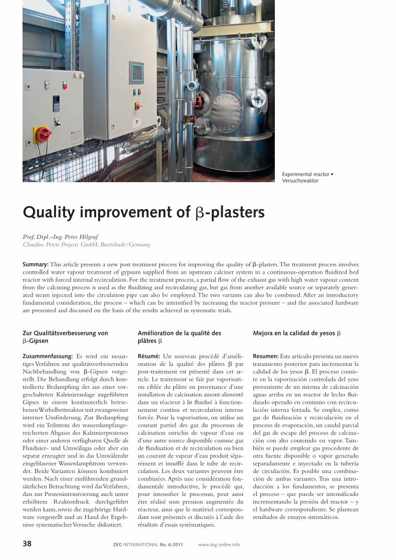
2.1 Properties/cost effectivenessAs an example, Table 1 compares properties of bplaster of Paris with those of ahemihydrate plaster, which is of higher quality but involves a more complex manufacturing process and is therefore more costintensive. The shown differences are consequences of the different crystal and surface morphologies of the two types of plaster that result from the production process. Figure 1 illustrates this by means of corresponding CP measurement results. It shows the dependency of the water/plaster ratio WGW, measured according to the strewable quantity process, on the specific surfaces aBET of the produced/treated plasters determined by the BET method. The curve “FGD plaster I” relates to a FGDgypsum processed in a flash calciner and subsequently postprocessed in different ways in the CP homogenizer described below. The righthand end point of the curve represents the non postprocessed plaster of Paris. As the BET surface aBET decreases, the WGW also decreases linearly through the measuring range. Whether the homogenizer is operated in continuous or batch mode is of no significance. The curve “FGD plaster II” also shows a linear dependency of the WGW(aBET). This curve relates to a different FGD raw gypsum that was calcined and postprocessed under systematically varied operating conditions in an indirectly heated rotary drum reactor working in batch mode. Due to the different operating parameters, the measured values inevitably show a larger scatter around the best fitting line. Other properties of the binder materials produced also correlate with the water/plaster ratio WGW, and thus with the surface structure of a plaster of Paris that is characterized by the BET surface aBET. Examples: the compressive strength RC and flexural tensile strength PF increase as the WGW decreases, the applicable equation being (RC, PF) ~ 1/WGW2, the commencement of setting tmin and end of setting tmax change in line with the WGW etc. For the rehydration of hemihydrate HH to dihydrate DH 1½ mols of water are necessary. The corresponding minimum water/plaster value referred to the mass of the hemihydrate and calculated with the combined water contents wDH = 0.2092 kgW/kgDH, wHH = 0.0621 kgW/kgHH is:
(MW ) = WGWmin = wDH – wHH
= 0.1860 MHH min 1 – wDH (1)
2.1 Eigenschaften/WirtschaftlichkeitTabelle 1 vergleicht beispielhaft Eigenschaften von bStuckStuckgips mit denjenigen des qualitativ höherwertigen, aber in der Herstellung aufwendigeren und damit auch kostenintensiveren aHalbhydratgipses. Die dort dargestellten UnterschiedeHalbhydratgipses. Die dort dargestellten Unterschiede lassen sich zwanglos auf die herstellungsbedingt verschiedenartigen Kristall/Oberflächenmorphologien beider Gipsarten zurückführen. Bild 1 verdeutlicht dies an Hand entsprechender CPMessergebnisse: Dargestellt ist die Abhängigkeit des Wasser/GipsWerts WGW, gemessen nach dem Einstreumengeverfahren, von den mit dem BETVerfahren ermittelten spezifischen Oberflächen aBET der erzeugten/behandelten Gipse. Die Kurve „FGD plaster I“ zeigt einen flashkalzinierten REAGips der im weiter unten beschriebenen CPHomogenisator unterschiedlichen Nachbehandlungen unterzogen wurde. Der rechte Endpunkt der Kurve entspricht dem nicht nachbehandelten Stuckgips. Mit kleiner werdender BETOberfläche aBET nimmt der WGW im Meßbereich linear ab. Die Betriebsweise des Homogenisators – kontinuierlich oder batchweise – ist ohne Einfluss. Eine lineare Abhängigkeit WGW(aBET) zeigt auch die Kurve „FGD plaster II“. Hier wurde ein weiterer REARohgips unter systematisch variierten Betriebsbedingungen in einem batchweise betriebenen,
0.40
0.45
0.50
0.55
0.60
0.65
0.70
2 4 6 8 10 12 14 16
Wat
er/p
last
er r
atio
WG
W [
kgW
/kg G
]
Specific surface acc. to BET aBET [m2/g]
FGD plaster I, continuous operation
FGD plaster I, batch operation I
FGD plaster I, batch operation II
FGD plaster II, batch operation
1 Dependency of the water/plaster ratio on the specific surface acc. to BET • Abhängigkeit des Wasser/Gips-Wertes von der spezi-fischen Oberfläche nach BET
Property/Eigenschaft b-plaster/b-Stuckgips a-HH plaster/a-HHGips
Crystal structure/Kristallausbildungfissured secondary crystals/
zerklüftete Sekundärkristallecompact primary crystals/ kompakte Primärkristalle
Specific surface acc. to BET/Spezifische Oberfläche nach BET [m2/g] approx./ca. 9–12 approx./ca. 4.5
Material density/Materialdichte [kg/m3]HH approx./ca. 2619 2757
Water/plaster ratio acc. to the strewing method/ Wasser/Gips-Wert nach dem Einstreuverfahren
[kgW/kgG] 0.65–0.75 approx./ca. 0.40
Flexural tensile strength/Biegezugfestigkeit [N/mm2] approx./ca. 5.0 approx./ca. 12.0
Compressive strength/Druckfestigkeit [N/mm2] approx./ca. 11.0 approx./ca. 45.0
Initial setting/Versteifungsbeginn [min] approx./ca. 6 approx./ca. 10
Final setting/Versteifungsende [min] approx./ca. 12 approx./ca. 20
Heat of hydration/Hydratationswärme [kJ/kgDH] 111.9 99.7
Solubility in water at 20 °C/Löslichkeit in Wasser bei 20 °C [gHH/kgW] 8.8 6.7
Particle disintegration upon rehydration/Kornzerfall bei Rehydratation yes/ja no/nein
Tab. 1: Comparison of the properties of a- and b-plasters • Eigenschaftsvergleich von a- und b-Gipsen
With: W = water, G = gypsum, HH = hemihydrate, DH = dihydrate, WGW = water/plaster ratioMit: W = Wasser, G = Gips, HH = Halbhydrat, DH = Dihydrat, WGW = Wasser/Gips-Wert
Process Know-how
41ZKG INTERNATIONAL No. 6-2011 www.zkg-online.info
The production of workable plasters demands significantly higher WGWs. The surplus water
∆MW = WGW – 0.1860
MHH (2)
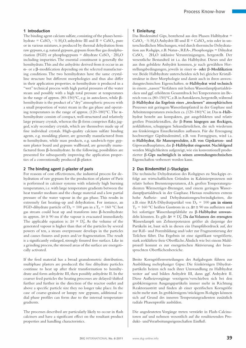
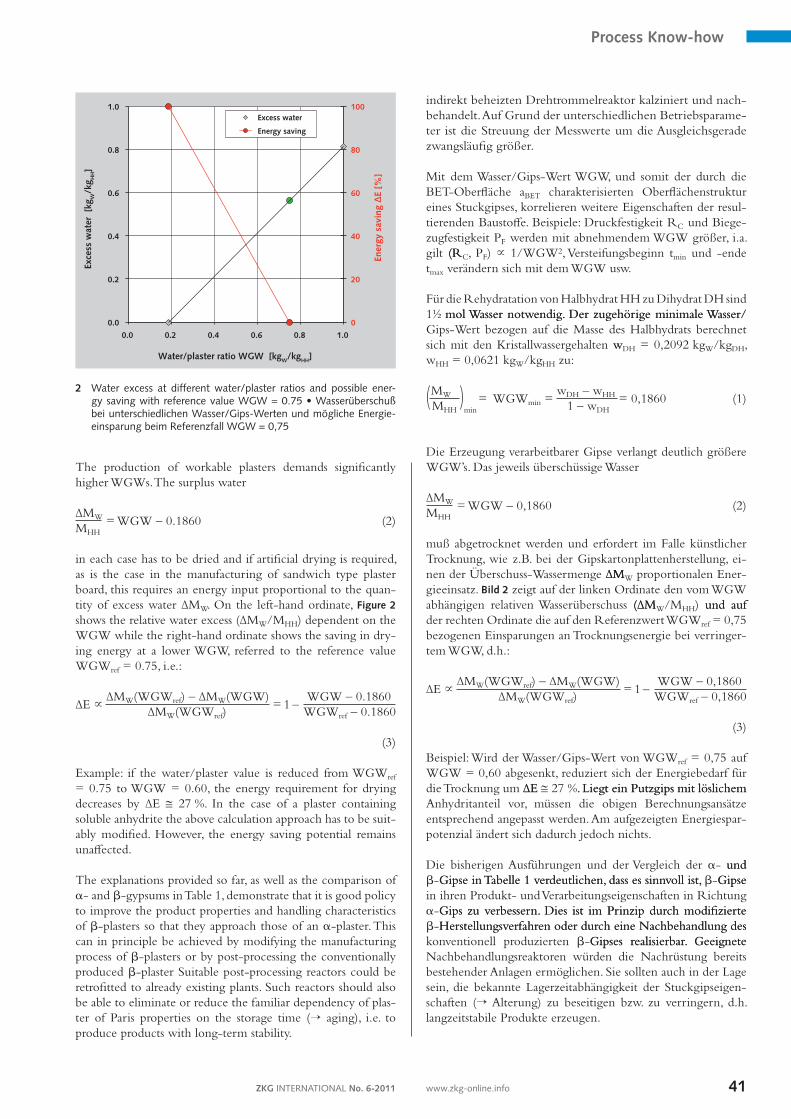
in each case has to be dried and if artificial drying is required, as is the case in the manufacturing of sandwich type plaster board, this requires an energy input proportional to the quantity of excess water ∆MW. On the lefthand ordinate, Figure 2 shows the relative water excess (∆MW/MHH) dependent on the WGW while the righthand ordinate shows the saving in drying energy at a lower WGW, referred to the reference value WGWref = 0.75, i.e.:
∆E ~ ∆MW(WGWref) – ∆MW(WGW)
= 1 – WGW – 0.1860
∆MW(WGWref) WGWref – 0.1860
(3) Example: if the water/plaster value is reduced from WGWref = 0.75 to WGW = 0.60, the energy requirement for drying decreases by ∆E @ 27 %. In the case of a plaster containing soluble anhydrite the above calculation approach has to be suitably modified. However, the energy saving potential remains unaffected. The explanations provided so far, as well as the comparison of a and bgypsums in Table 1, demonstrate that it is good policy to improve the product properties and handling characteristics of bplasters so that they approach those of an aplaster. This can in principle be achieved by modifying the manufacturing process of bplasters or by postprocessing the conventionally produced bplaster Suitable postprocessing reactors could be retrofitted to already existing plants. Such reactors should also be able to eliminate or reduce the familiar dependency of plaster of Paris properties on the storage time (→ aging), i.e. to produce products with longterm stability.
indirekt beheizten Drehtrommelreaktor kalziniert und nachbehandelt. Auf Grund der unterschiedlichen Betriebsparameter ist die Streuung der Messwerte um die Ausgleichsgerade zwangsläufig größer. Mit dem Wasser/GipsWert WGW, und somit der durch die BETOberfläche aBET charakterisierten Oberflächenstruktur eines Stuckgipses, korrelieren weitere Eigenschaften der resultierenden Baustoffe. Beispiele: Druckfestigkeit RC und Biegezugfestigkeit PF werden mit abnehmendem WGW größer, i.a. gilt (R(RC, PF) ~ 1/WGW2, Versteifungsbeginn tmin und ende tmax verändern sich mit dem WGW usw. Für die Rehydratation von Halbhydrat HH zu Dihydrat DH sind 1½ mol Wasser notwendig. Der zugehörige minimale Wasser/mol Wasser notwendig. Der zugehörige minimale Wasser/GipsWert bezogen auf die Masse des Halbhydrats berechnet sich mit den Kristallwassergehalten wwDH = 0,2092 kgW/kgDH, wHH = 0,0621 kgW/kgHH zu:
(MW ) = WGWmin = wDH – wHH
= 0,1860 MHH min 1 – wDH
(1)
Die Erzeugung verarbeitbarer Gipse verlangt deutlich größere WGW’s. Das jeweils überschüssige Wasser
∆MW = WGW – 0,1860
MHH (2)
muß abgetrocknet werden und erfordert im Falle künstlicher Trocknung, wie z.B. bei der Gipskartonplattenherstellung, einen der ÜberschussWassermenge ∆M∆MMW proportionalen Energieeinsatz. Bild 2 zeigt auf der linken Ordinate den vom WGW abhängigen relativen Wasserüberschuss (∆M(∆MW/MHH) und auf und auf der rechten Ordinate die auf den Referenzwert WGWref = 0,75 bezogenen Einsparungen an Trocknungsenergie bei verringertem WGW, d.h.:
∆E ~ ∆MW(WGWref) – ∆MW(WGW)
= 1 – WGW – 0,1860
∆MW(WGWref) WGWref – 0,1860
(3) Beispiel: Wird der Wasser/GipsWert von WGWref = 0,75 auf WGW = 0,60 abgesenkt, reduziert sich der Energiebedarf für die Trocknung um ∆E∆E @ 27 %. Liegt ein Putzgips mit löslichem. Liegt ein Putzgips mit löslichem Anhydritanteil vor, müssen die obigen Berechnungsansätze entsprechend angepasst werden. Am aufgezeigten Energiesparpotenzial ändert sich dadurch jedoch nichts. Die bisherigen Ausführungen und der Vergleich der a und und bGipse in Tabelle 1 verdeutlichen, dass es sinnvoll ist,Gipse in Tabelle 1 verdeutlichen, dass es sinnvoll ist, bGipseGipse in ihren Produkt und Verarbeitungseigenschaften in Richtung aGips zu verbessern. Dies ist im Prinzip durch modifizierteGips zu verbessern. Dies ist im Prinzip durch modifizierte bHerstellungsverfahren oder durch eine Nachbehandlung desHerstellungsverfahren oder durch eine Nachbehandlung des konventionell produzierten bGipses realisierbar. GeeigneteGipses realisierbar. Geeignete Nachbehandlungsreaktoren würden die Nachrüstung bereits bestehender Anlagen ermöglichen. Sie sollten auch in der Lage sein, die bekannte Lagerzeitabhängigkeit der Stuckgipseigenschaften (→ Alterung) zu beseitigen bzw. zu verringern, d.h. langzeitstabile Produkte erzeugen.
0
20
40
60
80
100
0.0
0.2
0.4
0.6
0.8
1.0
0.0 0.2 0.4 0.6 0.8 1.0
Ener
gy s
avin
g ∆
E [%
]
Exce
ss w
ater
[kg
W/k
g HH]
Water/plaster ratio WGW [kgW/kgHH]
Excess water
Energy saving
2 Water excess at different water/plaster ratios and possible ener-gy saving with reference value WGW = 0.75 • Wasserüberschuß bei unterschiedlichen Wasser/Gips-Werten und mögliche Energie-einsparung beim Referenzfall WGW = 0,75
Process Know-how
ZKG INTERNATIONAL No. 6-201142 www.zkg-online.info
2.2 Possibilities for influencing the qualityAs shown above, the properties of the gypsum binding agent are significantly determined by its surface structure, characterized here by aBET. The surface structure is influenced i.a. by the origin and granulometric distribution of the raw gypsum, the particular calcination process used, its operating temperature and the retention time of the plaster in the reactor. Further significant factors for the quality of the resultant product and for the WGW value that is necessary for its further processing are: the phase composition, the particle size and granulometric distribution, the particle shape and the degree of secondary particle disintegration of the plaster when mixed with water. Secondary particle decomposition takes place before noticeable commencement of the actual solution and hydration process and leads to a rise in WGW value due to the increase in freely accessible particle surfaces. There are essentially two ways of influencing the process in a postprocessing reactor:– artificial aging of the plaster,artificial aging of the plaster,– processing under high operating pressure.processing under high operating pressure. Artificial aging: The term aging means the stabilization and/or improvement of the processing properties of the calcium sulfate binding agent through the influence of moisture. If a plaster is spread out over a large area and subjected to a gas atmosphere containing water vapour, e.g. ambient air, the initial reaction is decomposition of AIII to HH. If the amount of available moisture is high enough (→ high relative gas moisture content and/or long contact period), the formation of DH subsequently occurs. The prerequisite for this is the existence of liquid water, which is precipitated in the pores and cracks of the particles and in the interstices between the particles as a consequence of capillary condensation and exists as adsorption layer at the free surfaces of the particles. The crystallization of DH takes place primarily at the areas of the particles that are activated by the burning process and leads to a partial filling and closure/covering of cracks and pores. It thus reduces the BET surface. An associated reduction in particle activation also occurs. The WGW decreases, as does the particle decomposition in the mixing water. However, no acceleration of the hydration process has been observed. The abovedescribed “natural” aging of plaster is not a practicable process in industrial systems as it takes a period of time between several hours and several days before the moisture in the plaster reaches a state of equilibrium. Moreover, the operating conditions vary due to fluctuations in the water vapour content of the ambient air. Particularly if the relative humidity is j ≥� 0.85, considerable absorption of moisture takes place, 0.85, considerable absorption of moisture takes place, sometimes over a period of weeks. As the interior of thicker/denser layers of binding agent is less accessible for the humidity than the outer surface, this leads to differing product qualities. In the case of natural aging the operating pressure and temperature cannot be influenced. However, by causing “artificial” aging, i.e. by supplying a defined quantity of water vapour or possibly water under controlled operating conditions to plaster in a suitably designed postprocessing reactor, it is possible to accelerate the aging process and eliminate the described difficulties.
2.2 EinflussmöglichkeitenWie oben gezeigt, werden die Eigenschaften des Bindemittels Gips wesentlich durch seine Oberflächenstruktur, hier charakterisiert durch aBET, bestimmt. Auf diese nehmen u.a. Herkunft und Korngrößenverteilung des Rohgipses, das spezielle Kalzinierverfahren, dessen Arbeitstemperatur sowie die Gipsverweilzeit im Reaktor Einfluss. Bedeutsam für die Qualität des resultierenden Produkts und den für seine Weiterverarbeitung notwendigen WGWWert sind des Weiteren die Phasenzusammensetzung, Partikelgröße und größenverteilung, Partikelform und der Grad des Sekundärpartikelzerfalls des Stuckgipses beim Anmischen mit Wasser. Letzteres erfolgt bevor der eigentliche Lösungs und Hydratationsvorgang merklich einsetzt und führt durch Vergrößerung der frei zugänglichen Partikeloberflächen zu einer Erhöhung des WGWWerts. Für einen Nachbehandlungsreaktor bieten sich im Wesentlichen zwei Möglichkeiten der Einflussnahme an:– Künstliche Alterung des Gipses,– Behandlung bei erhöhtem Betriebsdruck. Künstliche Alterung: Als Alterung wird die Stabilisierung und/oder Verbesserung der Verarbeitungseigenschaften des Bindemittels Gips durch Einwirkung von Feuchtigkeit bezeichnet. Setzt man einen großflächig ausgebreiteten Stuckgips einer Wasserdampf enthaltenden Gasatmosphäre, z.B. Umgebungsluft, aus, so wird zunächst das vorhandene AIII zu HH abgebaut. Danach kommt es bei ausreichendem Feuchtigkeitsangebot (→ hohe relative Gasfeuchtigkeit oder/und lange Kontaktzeit) zur Bildung von DH. Voraussetzung hierfür ist das Vorhandensein von flüssigem Wasser, das infolge Kapillarkondensation in den Poren und Rissen der Partikeln und den Zwickeln zwischen den Teilchen ausfällt sowie als Adsorptionsschicht an den freien Partikeloberflächen vorliegt. Die Auskristallisation des DH erfolgt bevorzugt an den durch die Brennprozessbeanspruchung aktivierten Partikelbereichen und führt zu einer partiellen Auffüllung bzw. zu einem Verschluss/einer Überdeckung von Rissen und Poren und somit zur Verkleinerung der BETOberfläche. Hiermit verbunden ist ein Abbau der Partikelaktivierung. Der WGW verringert sich, ebenso der Teilchenzerfall im Anmischwasser, eine Hydratationsbeschleunigung wird i. Allg. nicht beobachtet. Die oben beschriebene Vorgehensweise zur „natürlichen“ Alterung eines Gipses ist in Prozessanlagen nicht praktikabel: Es dauert einige Stunden bis zu mehreren Tagen bevor sich eine Gleichgewichtsfeuchte im Gips einstellt, außerdem verändern sich die Betriebsbedingungen bei Variation der Wasserdampfbeladung der Umgebungsluft. Insbesondere bei relativen Luftfeuchtigkeiten j ≥� 0,85 kommt es, teilweise über Wochen hinweg, zu einer erheblichen Feuchtigkeitsaufnahme. Da das Innere von dickeren/dichteren Bindemittelschichten für die Luftfeuchtigkeit nicht im gleichen Maße zugänglich ist wie deren äußere Oberfläche, führt dies zu unterschiedlichen Produktqualitäten. Betriebsdruck und temperatur sind bei der natürlichen Alterung nicht beeinflussbar. Durch „künstliche“ Alterung, d.h. der definierten Zufuhr von Wasserdampf oder ggf. Wasser unter kontrollierten Betriebsbedingungen zum Gips in einem geeignet gestalteten Nachbehandlungsreaktor, ist es möglich, den Alterungsprozess zu beschleunigen und die angesprochenen Schwierigkeiten zu beseitigen.
Process Know-how
43ZKG INTERNATIONAL No. 6-2011 www.zkg-online.info
Increased operating pressure: The quantity of water adhering adsorptively to a surface, in this case the accessible surface of plaster of Paris particles, rises with increasing partial pressure of the water vapour pWD in the surrounding gas atmosphere. This results in a high covering factor, in multilayer adsorption and in increased capillary condensation, i.a. due to modified pore geometries. An increase in the operating pressure pR of the postprocessing reactor while the moisture content of the gas remains unchanged k = MWD/MG,tr and the reactor temperature TR remains constant results in a proportional increase in the partial pressure of the water vapour pWD and also of the relative gas humidity j. Practical experience has shown that under these operating conditions a further reduction in the BET surface aBET occurs together with a simultaneous acceleration of the artificial aging process, partly because of the larger availability of water. The measuring points at the lefthand end of the curve “FGD plaster II” in Figure 1 originate from postprocessing trials performed with a reactor pressure of pR (1.75 bar(abs)). A further possible influencing variable is the post-processing temperature. This has to be harmonized with the upstream calcining process. This point will not be explicitly discussed here. Supplementary information regarding the abovedescribed relationships is contained in [14].
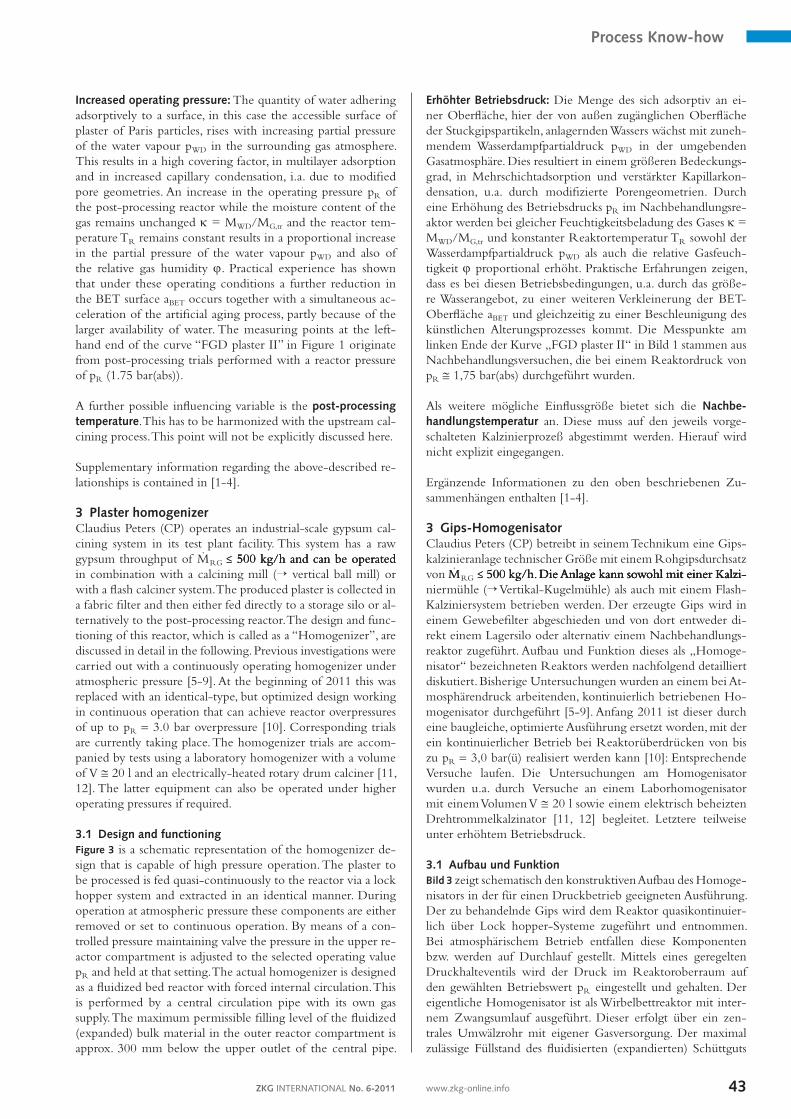
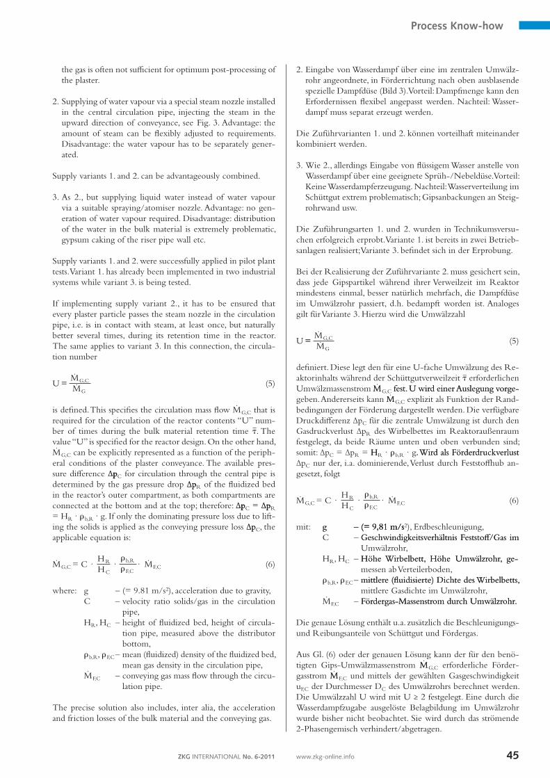
3 Plaster homogenizerClaudius Peters (CP) operates an industrialscale gypsum calcining system in its test plant facility. This system has a raw gypsum throughput of MRG �� 500 kg/h and can be operated�� 500 kg/h and can be operated 500 kg/h and can be operated in combination with a calcining mill (→ vertical ball mill) or with a flash calciner system. The produced plaster is collected in a fabric filter and then either fed directly to a storage silo or alternatively to the postprocessing reactor. The design and functioning of this reactor, which is called as a “Homogenizer”, are discussed in detail in the following. Previous investigations were carried out with a continuously operating homogenizer under atmospheric pressure [59]. At the beginning of 2011 this was replaced with an identicaltype, but optimized design working in continuous operation that can achieve reactor overpressures of up to pR = 3.0 bar overpressure [10]. Corresponding trials are currently taking place. The homogenizer trials are accompanied by tests using a laboratory homogenizer with a volume of V @ 20 l and an electricallyheated rotary drum calciner [11, 12]. The latter equipment can also be operated under higher operating pressures if required. 3.1 Design and functioningFigure 3 is a schematic representation of the homogenizer design that is capable of high pressure operation. The plaster to be processed is fed quasicontinuously to the reactor via a lock hopper system and extracted in an identical manner. During operation at atmospheric pressure these components are either removed or set to continuous operation. By means of a controlled pressure maintaining valve the pressure in the upper reactor compartment is adjusted to the selected operating value pR and held at that setting. The actual homogenizer is designed as a fluidized bed reactor with forced internal circulation. This is performed by a central circulation pipe with its own gas supply. The maximum permissible filling level of the fluidized (expanded) bulk material in the outer reactor compartment is approx. 300 mm below the upper outlet of the central pipe.
Erhöhter Betriebsdruck: Die Menge des sich adsorptiv an einer Oberfläche, hier der von außen zugänglichen Oberfläche der Stuckgipspartikeln, anlagernden Wassers wächst mit zunehmendem Wasserdampfpartialdruck pWD in der umgebenden Gasatmosphäre. Dies resultiert in einem größeren Bedeckungsgrad, in Mehrschichtadsorption und verstärkter Kapillarkondensation, u.a. durch modifizierte Porengeometrien. Durch eine Erhöhung des Betriebsdrucks pR im Nachbehandlungsreaktor werden bei gleicher Feuchtigkeitsbeladung des Gases k = MWD/MG,tr und konstanter Reaktortemperatur TR sowohl der Wasserdampfpartialdruck pWD als auch die relative Gasfeuchtigkeit j proportional erhöht. Praktische Erfahrungen zeigen, dass es bei diesen Betriebsbedingungen, u.a. durch das größere Wasserangebot, zu einer weiteren Verkleinerung der BETOberfläche aBET und gleichzeitig zu einer Beschleunigung des künstlichen Alterungsprozesses kommt. Die Messpunkte am linken Ende der Kurve „FGD plaster II“ in Bild 1 stammen aus Nachbehandlungsversuchen, die bei einem Reaktordruck von pR @ 1,75 bar(abs) durchgeführt wurden. Als weitere mögliche Einflussgröße bietet sich die Nachbe-handlungstemperatur an. Diese muss auf den jeweils vorgeschalteten Kalzinierprozeß abgestimmt werden. Hierauf wird nicht explizit eingegangen. Ergänzende Informationen zu den oben beschriebenen Zusammenhängen enthalten [14]. 3 Gips-HomogenisatorClaudius Peters (CP) betreibt in seinem Technikum eine Gipskalzinieranlage technischer Größe mit einem Rohgipsdurchsatz von MMRG �� 500 kg/h. Die Anlage kann sowohl mit einer Kalzi�� 500 kg/h. Die Anlage kann sowohl mit einer Kalzi 500 kg/h. Die Anlage kann sowohl mit einer Kalzi. Die Anlage kann sowohl mit einer Kalziniermühle (→ VertikalKugelmühle) als auch mit einem FlashKalziniersystem betrieben werden. Der erzeugte Gips wird in einem Gewebefilter abgeschieden und von dort entweder direkt einem Lagersilo oder alternativ einem Nachbehandlungsreaktor zugeführt. Aufbau und Funktion dieses als „Homogenisator“ bezeichneten Reaktors werden nachfolgend detailliert diskutiert. Bisherige Untersuchungen wurden an einem bei Atmosphärendruck arbeitenden, kontinuierlich betriebenen Homogenisator durchgeführt [59]. Anfang 2011 ist dieser durch eine baugleiche, optimierte Ausführung ersetzt worden, mit der ein kontinuierlicher Betrieb bei Reaktorüberdrücken von bis zu pR = 3,0 bar(ü) realisiert werden kann [10]: Entsprechende Versuche laufen. Die Untersuchungen am Homogenisator wurden u.a. durch Versuche an einem Laborhomogenisator mit einem Volumen V @ 20 l sowie einem elektrisch beheizten Drehtrommelkalzinator [11, 12] begleitet. Letztere teilweise unter erhöhtem Betriebsdruck. 3.1 Aufbau und FunktionBild 3 zeigt schematisch den konstruktiven Aufbau des Homogenisators in der für einen Druckbetrieb geeigneten Ausführung. Der zu behandelnde Gips wird dem Reaktor quasikontinuierlich über Lock hopperSysteme zugeführt und entnommen. Bei atmosphärischem Betrieb entfallen diese Komponenten bzw. werden auf Durchlauf gestellt. Mittels eines geregelten Druckhalteventils wird der Druck im Reaktoroberraum auf den gewählten Betriebswert pR eingestellt und gehalten. Der eigentliche Homogenisator ist als Wirbelbettreaktor mit internem Zwangsumlauf ausgeführt. Dieser erfolgt über ein zentrales Umwälzrohr mit eigener Gasversorgung. Der maximal zulässige Füllstand des fluidisierten (expandierten) Schüttguts
Process Know-how
ZKG INTERNATIONAL No. 6-201144 www.zkg-online.info
To allow the setting of different mean bulk material retention times
t{ = ∆MG
MG (4)
with: ∆MG – current plaster mass in the homogenizer,
MG – plaster mass flow through the homogenizer,
the height of the fluidized bed (~ plaster mass ∆MG in the reactor) can be set to lower values by means of a vertically adjustable filling level gauge. The bulk material is discharged from the homogenizer via an outlet pipe, whose inlet height over the distributer bottom can also be varied. Usual bplasters of Paris can be classified in the Geldart diagram [13] as group A to A/C bulk materials, i.e. they are relatively easy to fluidize and initially expand homogeneously above the minimum fluidization velocity uF,L through a limited gas velocity range before bubbles start to form. Although the bubbles formed are limited in size (→ they disintegrate into smaller bubbles once they have exceeded a critical diameter), they do assist mixing of the bulk material in the homogenizer. In the outer compartment of the reactor the selected fluidizing gas velocities are therefore above the respective bubble formation velocity uF,B. This velocity can be calculated [14]. Typical empty pipe gas velocities for plasters are in the range of uF,R @ 2 m/min and are independent of the reactor pressure pR. Gas velocities of uF,C ≥� (2.5 · u≥� (2.5 · u (2.5 · u · uuF,R) are selected for the circulation through the central pipe. The water vapour/water required for the postprocessing can be supplied in different ways: 1. A partial flow of the exhaust gas containing water vapour
from the upstream calcination process or another source can be used as fluidizing and circulation gas. Advantage: uniform distribution of the water vapour over the crosssection of the fluidized bed; no additional energy requirement for water evaporation. Disadvantage: the amount of water vapour in
im Reaktoraußenraum liegt ca. 300 mm unterhalb des oberen Zentralrohraustritts. Zur Einstellung unterschiedlicher mittlerer Schüttgutverweilzeiten
t{ = ∆MG
MG (4)
mit: ∆MG – aktuelle Gipsmasse im Homogenisator,aktuelle Gipsmasse im Homogenisator,
MG – Gipsmassenstrom durch den Homogenisator,Gipsmassenstrom durch den Homogenisator,
kann die Wirbelbetthöhe (~ Gipsmasse ∆M∆MG im Reaktor) mittels eines höhenverstellbaren Füllstandsmessers auf geringere Werte einreguliert werden. Der Austrag des Schüttguts aus dem Homogenisator erfolgt über ein Tauchrohr, dessen Einlaufhöhe über dem Verteilerboden ebenfalls variabel einstellbar ist. Übliche bStuckgipse lassen sichStuckgipse lassen sich im GeldartDiagramm [13] als Gruppe A bis A/CSchüttgüter klassifizieren, d.h. sie sind relativ einfach zu fluidisieren und expandieren oberhalb der Lockerungsgeschwindigkeit uF,L über einen begrenzten Gasgeschwindigkeitsbereich zunächst homogen bevor Blasenbildung einsetzt. Die entstehenden Blasen sind zwar in ihrer Größe begrenzt (→ sie zerfallen in kleinere Einheiten bei Überschreitung eines kritischen Durchmessers), unterstützen aber trotzdem die Vermischung des Schüttguts im Homogenisator. Im Reaktoraußenraum werden deshalb Fluidisiergasgeschwindigkeiten oberhalb der jeweiligen Blasenbildungsgeschwindigkeit uF,B gewählt. Diese kann berechnet werden [14]. Typische LeerrohrGasgeschwindigkeiten für Gipse liegen in der Größenordnung von uF,R @ 2 m/min und sind unabhängig vom Reaktordruck pR. Für die Umförderung durch das Zentralrohr werden Gasgeschwindigkeiten uF,C ≥� (2,5 · uF,R) gewählt. Die Zuführung des für die Nach
behandlung erforderlichen Wasserdampfs/Wassers kann auf unterschiedliche Weise erfolgen: 1. Nutzung eines Teilstroms der mit Wasserdampf angereicher
ten Abgase des vorgeschalteten Kalzinierprozesses oder einer anderen verfügbaren Quelle als Fluidisier und Umwälzgas. Vorteil: Gleichmäßige Wasserdampfverteilung über den Bettquerschnitt; kein zusätzlicher Energiebedarf für Wasserverdampfung. Nachteil: Wasserdampfanteil im Gas häufig nicht ausreichend für eine optimale Gipsnachbehandlung.
3 Schematic design of the homogenizer • Konstruktiver Aufbau des Homogenisators, schematisch
Process Know-how
45ZKG INTERNATIONAL No. 6-2011 www.zkg-online.info
the gas is often not sufficient for optimum postprocessing of the plaster.
2. Supplying of water vapour via a special steam nozzle installed in the central circulation pipe, injecting the steam in the upward direction of conveyance, see Fig. 3. Advantage: the amount of steam can be flexibly adjusted to requirements. Disadvantage: the water vapour has to be separately generated.
Supply variants 1. and 2. can be advantageously combined. 3. As 2., but supplying liquid water instead of water vapour
via a suitable spraying/atomiser nozzle. Advantage: no generation of water vapour required. Disadvantage: distribution of the water in the bulk material is extremely problematic, gypsum caking of the riser pipe wall etc.
Supply variants 1. and 2. were successfully applied in pilot plant tests. Variant 1. has already been implemented in two industrial systems while variant 3. is being tested. If implementing supply variant 2., it has to be ensured that every plaster particle passes the steam nozzle in the circulation pipe, i.e. is in contact with steam, at least once, but naturally better several times, during its retention time in the reactor. The same applies to variant 3. In this connection, the circulation number
U = = MG,C
MG (5)
is defined. This specifies the circulation mass flow MG,C that is required for the circulation of the reactor contents “U” number of times during the bulk material retention time t{. The value “U” is specified for the reactor design. On the other hand, MG,C can be explicitly represented as a function of the peripheral conditions of the plaster conveyance. The available pressure difference ∆p∆ppC for circulation through the central pipe is determined by the gas pressure drop ∆p∆ppR of the fluidized bed in the reactor’s outer compartment, as both compartments are connected at the bottom and at the top; therefore: ∆p∆ppC = ∆p∆ppR = HR · rb,R · g. If only the dominating pressure loss due to lifting the solids is applied as the conveying pressure loss ∆p∆pC, the applicable equation is:
MG,C = C · HR
· rb,R
· MF,C HC rF,C (6)
where: g – (= 9.81 m/s2), acceleration due to gravity, C – velocity ratio solids/gas in the circulation
pipe, HR, HC – height of fluidized bed, height of circula
tion pipe, measured above the distributor bottom,
rb,R, rF,C – mean (fluidized) density of the fluidized bed, mean gas density in the circulation pipe,
MF,C – conveying gas mass flow through the circulation pipe.
The precise solution also includes, inter alia, the acceleration and friction losses of the bulk material and the conveying gas.
2. Eingabe von Wasserdampf über eine im zentralen Umwälzrohr angeordnete, in Förderrichtung nach oben ausblasende spezielle Dampfdüse (Bild 3). Vorteil: Dampfmenge kann den Erfordernissen flexibel angepasst werden. Nachteil: Wasserdampf muss separat erzeugt werden.
Die Zuführvarianten 1. und 2. können vorteilhaft miteinander kombiniert werden. 3. Wie 2., allerdings Eingabe von flüssigem Wasser anstelle von
Wasserdampf über eine geeignete Sprüh/Nebeldüse. Vorteil: Keine Wasserdampferzeugung. Nachteil: Wasserverteilung im Schüttgut extrem problematisch; Gipsanbackungen an Steigrohrwand usw.
Die Zuführungsarten 1. und 2. wurden in Technikumsversuchen erfolgreich erprobt. Variante 1. ist bereits in zwei Betriebsanlagen realisiert; Variante 3. befindet sich in der Erprobung. Bei der Realisierung der Zuführvariante 2. muss gesichert sein, dass jede Gipspartikel während ihrer Verweilzeit im Reaktor mindestens einmal, besser natürlich mehrfach, die Dampfdüse im Umwälzrohr passiert, d.h. bedampft worden ist. Analoges gilt für Variante 3. Hierzu wird die Umwälzzahl
U = = MG,C
MG (5)
definiert. Diese legt den für eine Ufache Umwälzung des Reaktorinhalts während der Schüttgutverweilzeit t{ erforderlichen Umwälzmassenstrom M MG,C fest. U wird einer Auslegung vorgefest. U wird einer Auslegung vorgegeben. Andererseits kann MMG,C explizit als Funktion der Randbedingungen der Förderung dargestellt werden. Die verfügbare Druckdifferenz ∆pC für die zentrale Umwälzung ist durch den Gasdruckverlust ∆pR des Wirbelbettes im Reaktoraußenraum festgelegt, da beide Räume unten und oben verbunden sind; somit: ∆pC = ∆pR = HHR · rb,R · g.Wird als Förderdruckverlust. Wird als Förderdruckverlust ∆pC nur der, i.a. dominierende, Verlust durch Feststoffhub angesetzt, folgt
MG,C = C · HR
· rb,R
· MF,C HC rF,C (6)
mit: g – (= 9,81 m/s g – (= 9,81 m/s(= 9,81 m/s2), Erdbeschleunigung, C – Geschwindigkeitsverhältnis Feststoff/Gas imGeschwindigkeitsverhältnis Feststoff/Gas im
Umwälzrohr, HR, HC – Höhe Wirbelbett, Höhe Umwälzrohr, geHöhe Wirbelbett, Höhe Umwälzrohr, ge
messen ab Verteilerboden, rb,R, rF,C – mittlere (fluidisierte) Dichte des Wirbelbetts,mittlere (fluidisierte) Dichte des Wirbelbetts,
mittlere Gasdichte im Umwälzrohr, MF,C – FördergasMassenstrom durch Umwälzrohr.FördergasMassenstrom durch Umwälzrohr. Die genaue Lösung enthält u.a. zusätzlich die Beschleunigungs und Reibungsanteile von Schüttgut und Fördergas. Aus Gl. (6) oder der genauen Lösung kann der für den benötigten GipsUmwälzmassenstrom MMG,C erforderliche Fördergasstrom MMF,C und mittels der gewählten Gasgeschwindigkeit uF,C der Durchmesser DC des Umwälzrohrs berechnet werden. Die Umwälzzahl U wird mit U ≥� 2 festgelegt. Eine durch die Wasserdampfzugabe ausgelöste Belagbildung im Umwälzrohr wurde bisher nicht beobachtet. Sie wird durch das strömende 2Phasengemisch verhindert/abgetragen.
Process Know-how
ZKG INTERNATIONAL No. 6-201146 www.zkg-online.info
The conveying gas flow MF,C needed for the required plaster circulation mass flow MG,C can be calculated from equation (6) or the precise solution and the diameter DC of the circulation pipe can be calculated by means of the selected gas velocity uF,C. The number of circulations U is defined as U ≥� 2. Up to now,≥� 2. Up to now, 2. Up to now, it has not been observed that the supply of water vapour causes coatings to form inside the circulation pipe. This is prevented by the 2phase mixture flowing through the pipe. Characteristic values and their dependency on the respective operating condition, e.g. on rb,F(uF,R), are required for designing the reactor. The calculation approaches and models proposed in the literature for this purpose are only of limited precision and are therefore checked by laboratory experiments for design purposes. Overall, the operating behaviour of the reactor permits precalculation and safe scaleup. A newly developed design program enables the performance of detailed analyses [15]. The homogenizer can be equipped with socalled agitators to mechanically assist the formation of a fluidized bed if the plaster is cohesive and very difficult to fluidize. This can be necessary, for example, in the case of products from the lefthand section of Geldart group C. Alternatively, a pulsating active/inactive bottom aeration can be used. With some sorts of plaster, the handling properties and product characteristics can be improved by intensive mechanical stressing/activation such as that rendered by the agitators. This particularly applies to phosphoric gypsums. The main technical data of the CP test homogenizer are: fluidized bed diameter DR = 1.0 m; maximum fluidized bed height HR,max @ 1.3 m; overall height of reactor Hges @ 2.6 m; inside diameter of circulation pipe DC = 212.7 mm; permissible reactor overpressure pR = 3.5 bar overpressure; plaster throughput MG �� 500 kg/h; reactor completely thermally insulated with�� 500 kg/h; reactor completely thermally insulated with 500 kg/h; reactor completely thermally insulated with electrical heating underneath the insulation; fluidization gas and circulation gas heated up by electrical heating coil in the supply pipe; electrically heated water vapour generator; including pressure maintenance, inlet and discharge systems; complete set of instruments with control system and integration into the higherlevel calciner system.
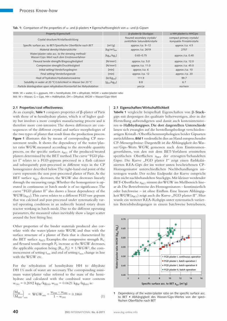
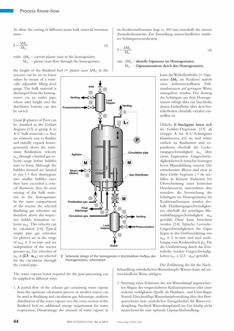
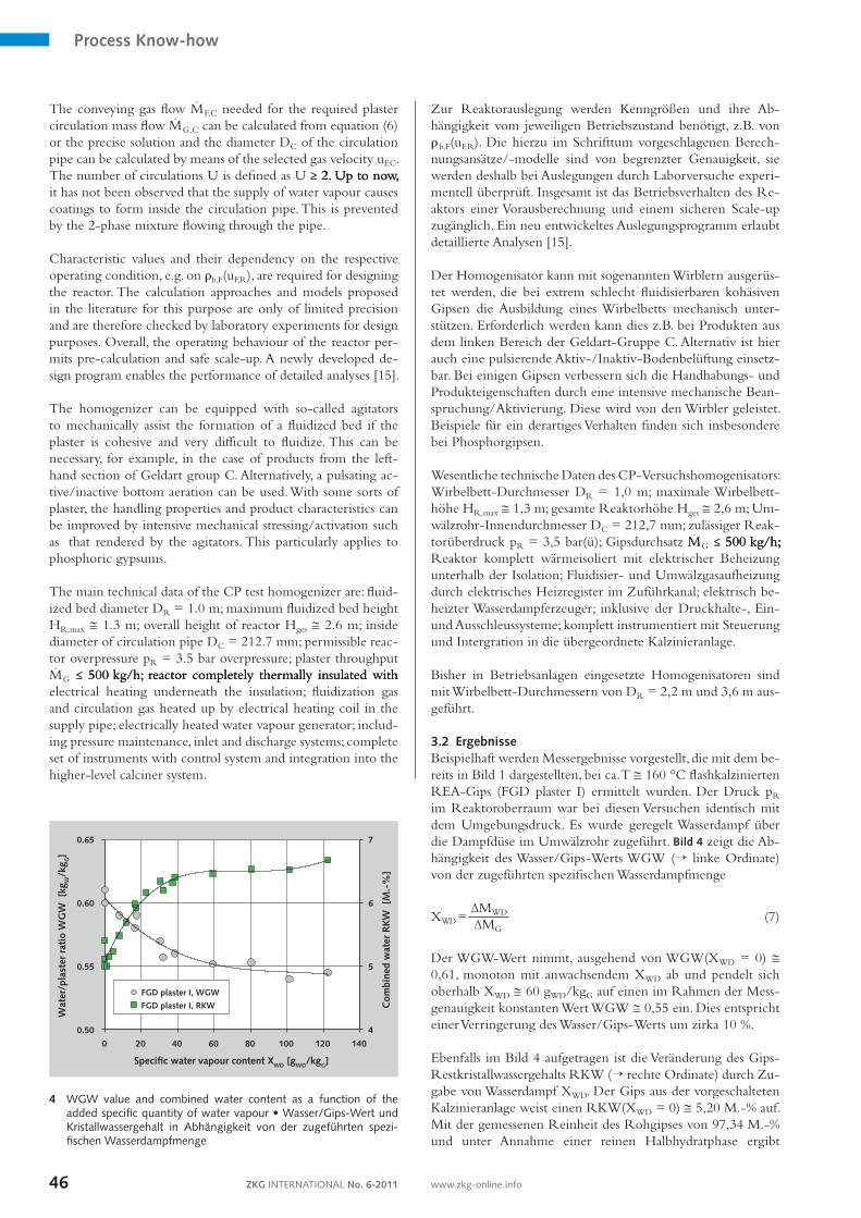
Zur Reaktorauslegung werden Kenngrößen und ihre Abhängigkeit vom jeweiligen Betriebszustand benötigt, z.B. von rb,F(uF,R). Die hierzu im Schrifttum vorgeschlagenen Berechnungsansätze/modelle sind von begrenzter Genauigkeit, sie werden deshalb bei Auslegungen durch Laborversuche experimentell überprüft. Insgesamt ist das Betriebsverhalten des Reaktors einer Vorausberechnung und einem sicheren Scaleup zugänglich. Ein neu entwickeltes Auslegungsprogramm erlaubt detaillierte Analysen [15]. Der Homogenisator kann mit sogenannten Wirblern ausgerüstet werden, die bei extrem schlecht fluidisierbaren kohäsiven Gipsen die Ausbildung eines Wirbelbetts mechanisch unterstützen. Erforderlich werden kann dies z.B. bei Produkten aus dem linken Bereich der GeldartGruppe C. Alternativ ist hier auch eine pulsierende Aktiv/InaktivBodenbelüftung einsetzbar. Bei einigen Gipsen verbessern sich die Handhabungs und Produkteigenschaften durch eine intensive mechanische Beanspruchung/Aktivierung. Diese wird von den Wirbler geleistet. Beispiele für ein derartiges Verhalten finden sich insbesondere bei Phosphorgipsen. Wesentliche technische Daten des CPVersuchshomogenisators: WirbelbettDurchmesser DR = 1,0 m; maximale Wirbelbetthöhe HR,max @ 1,3 m; gesamte Reaktorhöhe Hges @ 2,6 m; UmwälzrohrInnendurchmesser DC = 212,7 mm; zulässiger Reaktorüberdruck pR = 3,5 bar(ü); Gipsdurchsatz MMG �� 500 kg/h;�� 500 kg/h; 500 kg/h;; Reaktor komplett wärmeisoliert mit elektrischer Beheizung unterhalb der Isolation; Fluidisier und Umwälzgasaufheizung durch elektrisches Heizregister im Zuführkanal; elektrisch beheizter Wasserdampferzeuger; inklusive der Druckhalte, Ein und Ausschleussysteme; komplett instrumentiert mit Steuerung und Intergration in die übergeordnete Kalzinieranlage. Bisher in Betriebsanlagen eingesetzte Homogenisatoren sind mit WirbelbettDurchmessern von DR = 2,2 m und 3,6 m ausgeführt. 3.2 ErgebnisseBeispielhaft werden Messergebnisse vorgestellt, die mit dem bereits in Bild 1 dargestellten, bei ca. T @ 160 °C flashkalzinierten REAGips (FGD plaster I) ermittelt wurden. Der Druck pR im Reaktoroberraum war bei diesen Versuchen identisch mit dem Umgebungsdruck. Es wurde geregelt Wasserdampf über die Dampfdüse im Umwälzrohr zugeführt. Bild 4 zeigt die Abhängigkeit des Wasser/GipsWerts WGW (→ linke Ordinate) von der zugeführten spezifischen Wasserdampfmenge
XWD = ∆MWD
∆MG (7)
Der WGWWert nimmt, ausgehend von WGW(XWD = 0) @ 0,61, monoton mit anwachsendem XWD ab und pendelt sich oberhalb XWD @ 60 gWD/kgG auf einen im Rahmen der Messgenauigkeit konstanten Wert WGW @ 0,55 ein. Dies entspricht einer Verringerung des Wasser/GipsWerts um zirka 10 %. Ebenfalls im Bild 4 aufgetragen ist die Veränderung des GipsRestkristallwassergehalts RKW (→ rechte Ordinate) durch Zugabe von Wasserdampf XWD. Der Gips aus der vorgeschalteten Kalzinieranlage weist einen RKW(XWD = 0) @ 5,20 M.% auf. Mit der gemessenen Reinheit des Rohgipses von 97,34 M.% und unter Annahme einer reinen Halbhydratphase ergibt
4
5
6
7
0.50
0.55
0.60
0.65
0 20 40 60 80 100 120 140
Com
bine
d w
ater
RK
W [
M.-
%]
Wat
er/p
last
er r
atio
WG
W [
kgW
/kg G
]
Specific water vapour content XWD [gWD/kgG]
FGD plaster I, WGW
FGD plaster I, RKW
4 WGW value and combined water content as a function of the added specific quantity of water vapour • Wasser/Gips-Wert und Kristallwassergehalt in Abhängigkeit von der zugeführten spezi-fischen Wasserdampfmenge
Process Know-how
47ZKG INTERNATIONAL No. 6-2011 www.zkg-online.info
Up to now, homogenizers installed in industrial plants have been equipped with fluidized bed diameters of DR = 2.2 m and 3.6 m.
3.2 ResultsAs an example, measurement results are presented that were obtained with the FGD plaster I shown in Figure 1 which was produced in a flash calciner at approx. T @ 160°C. For these tests the pressure pR in the upper reactor compartment was identical with the ambient pressure. Water vapour was supplied at a controlled rate to the circulation pipe via the steam nozzle. Figure 4 shows the dependency of the water/plaster ratio WGW (→ lefthand ordinate) on the added specific quantity of water vapour
XWD = ∆MWD
∆MG (7)
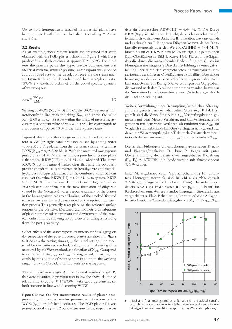
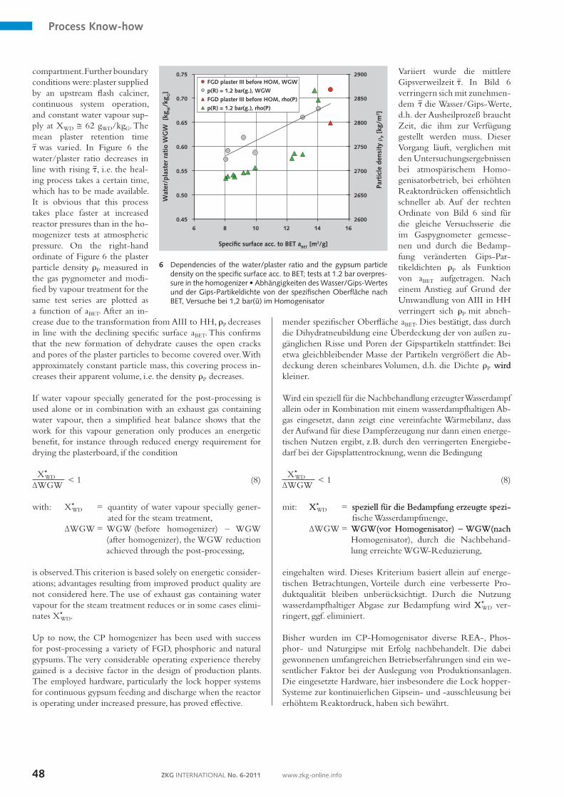
Starting at WGW(XWD = 0) @ 0.61, the WGW decreases monotonously in line with the rising XWD and above the value XWD @ 60 gWD/kgG it settles within the limits of measuring accuracy at a constant value of WGW @ 0.55. This corresponds to a reduction of approx. 10 % in the water/plaster ratio. Figure 4 also shows the change in the combined water content RKW (→ righthand ordinate) caused by adding water vapour XWD. The plaster from the upstream calciner system has RKW(XWD = 0) @ 5.20 M.%. With the measured raw gypsum purity of 97.34 M.% and assuming a pure hemihydrate phase a theoretical RKW(HH) = 6.04 M.% is obtained. The curve RKW(XWD) in Figure 4 makes clear that first the obviously present anhydrite III is converted to hemihydrate and that dihydrate is subsequently formed, as the combined water content rises past the value RKW(HH) = 6.04 M.%. to approx. RKW @ 6.50 M.%. The measured BET surfaces in Figure 1, curve FGD plaster I, confirm that the new formation of dihydrate caused by the (adequate) water vapour treatment of the plaster in the homogenizer leads to a “healing” of the cracked/fissured surface structure that had been caused by the upstream calcination process. This primarily takes place on the activated surface regions of the particles. Measured granulometric distributions of plaster samples taken upstream and downstream of the reactor confirm this by showing no differences or changes resulting from the postprocessing. Other effects of the water vapour treatment/artificial aging on the properties of the postprocessed plaster are shown in Figure 5. It depicts the setting times tmin, the initial setting time measured by the knifecut method, and tmax, the final setting time measured by the Vicat method, as a function of XWD. Compared to untreated plaster, tmin and tmax are lengthened, in part significantly, by the addition of water vapour. In addition, the working range (tmax tmin) broadens in line with increasing XWD. The compressive strength RC and flexural tensile strength PF that were measured in previous tests follow the abovedescribed relationship (RC, PF) ~ 1/WGW2 with good agreement, i.e. both increase in line with decreasing WGW. Figure 6 shows the first measurement results of plaster postprocessing at increased reactor pressure as a function of the WGW(aBET) (→ lefthand ordinate). The FGD plaster III, was postprocessed at pR = 1.2 bar overpressure in the upper reactor
sich ein theoretischer RKW(HH) = 6,04 M.%. Die Kurve RKW(XWD) in Bild 4 verdeutlicht, dass sich zunächst das offensichtlich vorhandene Anhydrit III in Halbhydrat umwandelt und es danach zur Bildung von Dihydrat kommt, da der Restkristallwassergehalt über den Wert RKW(HH) = 6,04 M.%. hinaus bis auf ca. RKW @ 6,50 M.% ansteigt. Die gemessenen BETOberflächen in Bild 1, Kurve FGD Plaster I, bestätigen, dass die durch die (ausreichende) Bedampfung des Gipses im Homogenisator ausgelöste Dihydratneubildung zu einer „Ausheilung“ der durch den vorgeschalteten Kalzinierprozess aufgerissenen/zerklüfteten Oberflächenstruktur führt. Dies findet bevorzugt an den aktivierten Oberflächenregionen der Partikeln statt. Gemessene Korngrößenverteilungen von Gipsproben, die vor und nach dem Reaktor entnommen wurden, bestätigen das: Sie weisen keine Unterschiede bzw. Veränderungen durch die Nachbehandlung auf. Weitere Auswirkungen der Bedampfung/künstlichen Alterung auf die Eigenschaften der behandelten Gipse zeigt Bild 5. Dargestellt sind die Versteifungszeiten tmin, Versteifungsbeginn gemessen mit dem MesserVerfahren, und tmax, Versteifungsende gemessen mit dem VicatVerfahren, als Funktion von XWD. Im Vergleich zum unbehandelten Gips verlängern sich tmin und tmax durch die Wasserdampfzugabe z. T. deutlich. Zusätzlich verbreitert sich der Arbeitsbereich (tmax tmin) mit wachsendem XWD. Die in den bisherigen Untersuchungen gemessenen Druck und Biegezugfestigkeiten RC bzw. PF folgen mit guter Übereinstimmung der bereits oben angegebenen Beziehung (RC, PF) ~ 1/WGW2, d.h. beide werden mit abnehmendem WGW größer. Erste Messergebnisse einer Gipsnachbehandlung bei erhöhtem Homogenisatordruck sind in Bild 6 als Abhängigkeit WGW(aBET) dargestellt (→ linke Ordinate). Behandelt wurde ein REAGips, FGD plaster III, bei pR = 1,2 bar(ü) im Reaktoroberraum. Weitere Randbedingungen: Gipszufuhr aus vorgeschalteter FlashKalzinierung, kontinuierlicher Anlagenbetrieb, konstante Wasserdampfzugabe von XWD @ 62 gWD/kgG.
0
2
4
6
8
10
12
0 20 40 60 80 100 120 140
Init
ial t
min/fi
nal s
etti
ng t
ime
t max
[m
in]
Specific water vapour content XWD [gWD/kgG]
FGD plaster I, t(min)
FGD plaster I, t(max)
5 Initial and final setting time as a function of the added specific quantity of water vapour • Versteifungsbeginn und -ende in Ab-hängigkeit von der zugeführten spezifischen Wasserdampfmenge
Process Know-how
ZKG INTERNATIONAL No. 6-201148 www.zkg-online.info
compartment. Further boundary conditions were: plaster supplied by an upstream flash calciner, continuous system operation, and constant water vapour supply at XWD @ 62 gWD/kgG. The mean plaster retention time t{ was varied. In Figure 6 the water/plaster ratio decreases in line with rising t{, i.e. the healing process takes a certain time, which has to be made available. It is obvious that this process takes place faster at increased reactor pressures than in the homogenizer tests at atmospheric pressure. On the righthand ordinate of Figure 6 the plaster particle density rP measured in the gas pygnometer and modified by vapour treatment for the same test series are plotted as a function of aBET. After an increase due to the transformation from AIII to HH, rP decreases in line with the declining specific surface aBET. This confirms that the new formation of dehydrate causes the open cracks and pores of the plaster particles to become covered over. With approximately constant particle mass, this covering process increases their apparent volume, i.e. the density rP decreases. If water vapour specially generated for the postprocessing is used alone or in combination with an exhaust gas containing water vapour, then a simplified heat balance shows that the work for this vapour generation only produces an energetic benefit, for instance through reduced energy requirement for drying the plasterboard, if the condition
X*WD
< 1∆WGW
(8)
with: X*
WD = quantity of water vapour specially generated for the steam treatment,
∆WGW = WGW (before homogenizer) – WGW (after homogenizer), the WGW reduction achieved through the postprocessing,
is observed. This criterion is based solely on energetic considerations; advantages resulting from improved product quality are not considered here. The use of exhaust gas containing water vapour for the steam treatment reduces or in some cases eliminates X*
WD. Up to now, the CP homogenizer has been used with success for postprocessing a variety of FGD, phosphoric and natural gypsums. The very considerable operating experience thereby gained is a decisive factor in the design of production plants. The employed hardware, particularly the lock hopper systems for continuous gypsum feeding and discharge when the reactor is operating under increased pressure, has proved effective.
Variiert wurde die mittlere Gipsverweilzeit t{. In Bild 6 verringern sich mit zunehmendem t{ die Wasser/GipsWerte, d.h. der Ausheilprozeß braucht Zeit, die ihm zur Verfügung gestellt werden muss. Dieser Vorgang läuft, verglichen mit den Untersuchungsergebnissen bei atmospärischem Homogenisatorbetrieb, bei erhöhten Reaktordrücken offensichtlich schneller ab. Auf der rechten Ordinate von Bild 6 sind für die gleiche Versuchsserie die im Gaspygnometer gemessenen und durch die Bedampfung veränderten GipsPartikeldichten rP als Funktion von aBET aufgetragen. Nach einem Anstieg auf Grund der Umwandlung von AIII in HH verringert sich rP mit abneh
mender spezifischer Oberfläche aBET. Dies bestätigt, dass durch die Dihydratneubildung eine Überdeckung der von außen zugänglichen Risse und Poren der Gipspartikeln stattfindet: Bei etwa gleichbleibender Masse der Partikeln vergrößert die Abdeckung deren scheinbares Volumen, d.h. die Dichte rP wirdwird kleiner. Wird ein speziell für die Nachbehandlung erzeugter Wasserdampf allein oder in Kombination mit einem wasserdampfhaltigen Abgas eingesetzt, dann zeigt eine vereinfachte Wärmebilanz, dass der Aufwand für diese Dampferzeugung nur dann einen energetischen Nutzen ergibt, z.B. durch den verringerten Energiebedarf bei der Gipsplattentrocknung, wenn die Bedingung
X*WD
< 1∆WGW
(8)
mit: X X*
WD = speziell für die Bedampfung erzeugte spezispeziell für die Bedampfung erzeugte spezifische Wasserdampfmenge,
∆WGW = WGW(vor Homogenisator) – WGW(nachWGW(vor Homogenisator) – WGW(nach Homogenisator), durch die Nachbehandlung erreichte WGWReduzierung,
eingehalten wird. Dieses Kriterium basiert allein auf energetischen Betrachtungen, Vorteile durch eine verbesserte Produktqualität bleiben unberücksichtigt. Durch die Nutzung wasserdampfhaltiger Abgase zur Bedampfung wird XX*
WD verringert, ggf. eliminiert. Bisher wurden im CPHomogenisator diverse REA, Phosphor und Naturgipse mit Erfolg nachbehandelt. Die dabei gewonnenen umfangreichen Betriebserfahrungen sind ein wesentlicher Faktor bei der Auslegung von Produktionsanlagen. Die eingesetzte Hardware, hier insbesondere die Lock hopperSysteme zur kontinuierlichen Gipsein und ausschleusung bei erhöhtem Reaktordruck, haben sich bewährt.
2600
2650
2700
2750
2800
2850
2900
0.45
0.50
0.55
0.60
0.65
0.70
0.75
6 8 10 12 14 16
Part
icle
den
sity
rP
[kg/
m3 ]
Wat
er/p
last
er r
atio
WG
W [
kgW
/kg G
]
Specific surface acc. to BET aBET [m2/g]
FGD plaster III before HOM, WGW
p(R) = 1.2 bar(g.), WGW
FGD plaster III before HOM, rho(P)
p(R) = 1.2 bar(g.), rho(P)
6 Dependencies of the water/plaster ratio and the gypsum particle density on the specific surface acc. to BET; tests at 1.2 bar overpres-sure in the homogenizer • Abhängigkeiten des Wasser/Gips-Wertes und der Gips-Partikeldichte von der spezifischen Oberfläche nach BET, Versuche bei 1,2 bar(ü) im Homogenisator
Process Know-how
Literature/Literaturverzeichnis
[1] Fischer, H.B.; Nowak, S., Müller, M.: Calciumsulfate und Luftfeuchtigkeit. ZKG INTERNATIONAL 60 (2007) No. 2, pp. 4861.
[2] Oetzel, M., Heger, G., Koslowski, T.: Einfluss von Umgebungsfeuchte und Temperatur auf die Phasenumwandlungen im System CaSO4H2O. ZKG INTERNATIONAL 53 (2000) No. 6, pp. 354361.
[3] Abdussamatowitsch, A. B.: Untersuchungen zur hygromechanischen Stabilität von kristallinem CalciumsulfatHalbhydrat. Dissertation, BauhausUniversität Weimar (2003).
[4] Blow, Ch., Bruce, B. Murray, G.: Water demand reduction of bhemihydrate plasters. Global gypsum MAGAZIN, MayJune 2010, pp. 1423.
[5] Anders, D.: Inbetriebnahme und Untersuchungen eines neuartigen Reaktors zur Optimierung der Calzinierung von REAGips. Diploma Thesis, Hamburg University of Applied Sciences, Department Life Sciences 2006, unpublished.
[6] Müller, D.: Zur künstlichen Alterung von Gips aus der Flashkalzinierung. Diploma Thesis, Hamburg University of Applied Sciences, Department Life Sciences 2007, unpublished.
[7] Schuldt, Th.: Experimentelle Untersuchungen zur Kalzinierung von PhosphorsäureAbfallgips. Diploma Thesis, Hamburg University of Applied Sciences, Department Life Sciences 2008, unpublished.
[8] Tsagas, N.: Vergleichende Herstellung von REA, Phosphor und Naturgips an einer technischen Anlage. Diploma Thesis, Hamburg
University of Applied Sciences, Department Life Sciences 2009, unpublished.
[9] Ndieula, C.: Untersuchungen zum Verhalten von REAGips mit und ohne künstlicher Alterung. Diploma Thesis, Hamburg University of Applied Sciences, Department Life Sciences 2009, unpublished.
[10] Neuelmann, H.: Projektierung einer Versuchsanlage zur Herstellung von Hochwertgipsen. Bachelor Thesis, Hamburg University of Applied Sciences, Department Life Sciences 2010, unpublished.
[11] Meinhardt, A.: Aufbau und Erprobung einer Versuchsanlage zur systematischen Herstellung unterschiedlicher Gipsqualitäten. Diploma Thesis, Hamburg University of Applied Sciences, Department Life Sciences 2005, unpublished.
[12] Claudius Peters Technologies: „Gipsherstellung und alterung in einem elektrisch beheizten Drehtrommelkalzinator“, R&D report, Buxtehude/Germany 01/2008, unpublished.
[13] Geldart, D.: Types of gas fluidization. Powder Technol. 7 (1973), pp. 285292.
[14] Geldart; D. (Edit.): Gas Fluidization Technology. Chichester: John Wiley & Sons 1986.
[15] Tchouanteu, R.: Entwicklung eines Auslegungsprogramms für den CPPGipshomogenisator. Diploma Thesis, Hamburg University of Applied Sciences, Department Life Sciences 2010, unpublished.
ZKG INTERNATIONAL No. 6-201150 www.zkg-online.info