Embed Size (px)
Citation preview
UNTERSUCHUNGEN ZUR ON-WING REINIGUNG VON KOMMERZIELLEN FLUGZEUGTRIEBWERKEN MIT CO2-
TROCKENEIS
INVESTIGATIONS INTO THE ON-WING CLEANING OF COMMERCIAL JET ENGINES WITH CO2 DRY ICE BLASTING
�S. Giljohann*, K. Bräutigam*
S. Kuhn**, S. Annasiri**, G. Ruß**
*Lufthansa Technik AG ** Hochschule Darmstadt, University of Applied Sciences
�Abstract
An experimental and numerical study has been conducted to evaluate the parameter of a CO2 dry ice cleaning process for the compressor of a jet engine. The cleaning process itself should be later on able to achieve a substantial increase of the EGT margin, going along with a reduction of the fuel flow. In contrast to the current usage of CO2 dry ice as a detergent in the part cleaning process, the targeted method should allow the cleaning of the compressor, while the engine is on wing and the service openings are left closed. The experiments have been conducted in a test rig, which allows the motoring of the compressor with an electrical engine. The accompanying simulation work has been performed to allow a deeper insight view of the flow and CO2 particle behaviour in the compressor. First results indicate that a cleaning effect is possible up to stage 6 of the high pressure compressor. Further work is necessary to intensify the cleaning, which should help to loosen also contaminations with a high adhesion and to increase the areas within the compressor, which are subject of the cleaning process. �
1. INTRODUCTION
�
One source of the in service performance loss of jet engines is, beside of the erosion of blade material [1], the contamination of the compressor with ingested material from the ambient air. The deposits on the compressor blades and vanes as well as the casing are influencing the aerodynamic within the compressor negatively and thus decreasing the compressor’s efficiency. The deposited material, which can be found, is ranging from ambient dust, sand and pollen to soot and left over from birds. The main indicators for the performance loss are the EGT margin and the fuel flow, which are continuously monitored while the engine is operated.
A number of different cleaning procedures have been developed in the past with the intention to provide an easy, on wing cleaning of the compressor. Also the detergent, which has been applied, does vary from coke, over nut shells to water.
However, the intention of this paper is to provide fundamental results of a research study into the cleaning of the compressor with CO2 dry ice. The usage of CO2 dry ice for cleaning of compressor parts, mostly compressor blades and vanes, is a
common technology within the maintenance of jet engines, once a full disassembly of the compressor is anyhow required. In contrast to this part cleaning process, the current study has been started with the target to provide process parameters for the CO2dry ice cleaning process of the engine on wing. A further requirement has been the restriction that no run up is necessary after the cleaning process and the whole cleaning process should not exceed one hour. As an advantage of the cleaning with CO2 dry ice pellets it can be mentioned, that no liquid or solid residuals of the cleaning agent will be left, which helps to apply this method independently of the weather conditions.
Based on the given limitations the preferred way to inject the CO2 dry ice into the compressor is via the inlet nozzle of the jet engine with a stationary device through the fan or with a rotating injector adjusted to the fan shaft, thus injecting the CO2 dry ice pellets directly into the LPC. The parameters for both methods have been studied and optimized in a test rig, which has been designed for this investigation. A two shaft jet engine, installed in this test rig, can be motored with an electrical engine, to simulate the starter operation. Several nozzles and injection devices for CO2 dry ice have been tested and the cleaning effect on a model contamination has been assessed. In addition also process parameters like injection air pressure, pellet size and quality, shaft
Deutscher Luft- und Raumfahrtkongress 2012
1
DocumentID: 281468
speed and nozzle positions were investigated.
For a further understanding of the interaction of the CO2 dry ice pellets with the flow as well as the blades and vanes in the low pressure compressor (LPC) and high pressure compressor (HPC) a numerical simulation has been performed. The numerical model has been set up in the ANSYS®
CFD suite and includes the fan, the LPC and the HPC in combination with the related casings.
��
2. BASIC CONSIDERATIONS
2.1 Cleaning with CO2 dry ice
�
The cleaning with CO2 dry ice has been investigated in the past in several fundamental studies as for example in [2], [3] and [4]. In general three cleaning effects are discussed in the literature: cleaning due to the abrasive effect of the solid carbon dioxide particles hitting the surface with a high speed, stress effects between the base material and the surface contamination due to thermal gradients induced while the pellets are cooling down the surface and cleaning due to the shock wave, which is induced by the sudden sublimation of carbon dioxide and the resulting volume increase by the factor 700.
However, in most of the studies it was found, that the main contribution to the total cleaning results from the mechanical interaction between the carbon dioxide particles and the contamination and thus can be contributed to an abrasive effect. Since the hardness of the CO2 dry ice pellets is low (TE 1.5 Mohs) the abrasive effect is mainly caused by the high speed the particles are gaining in the nozzle and the mass of the particles.
With regard to the overall removal of the contamination the thermal effect is ranked second, but can be pronounced, in case the temperature of the contaminated good is raised. In [4] the share of the thermal effect could be increased from about 15% at temperatures around 20°C to 51% at 500°C. This is of course depending on the structure and composition of the contamination and the interaction between contamination and base material. In [5] the removal of an insulation layer has been studied, which is coated on a turbine blade. In this case the coating does show in addition to the adhesive forces to the base material also cohesive forces in the layer itself. Together with the thermally induced stresses, those forces can cause the occurrence of cracks in the layer itself and between layer and base material.
The pressure shock due to the sudden sublimation of a certain quantity of solid carbon dioxide is in most cases ranked third with a contribution to the overall cleaning result of lower than 5%.
Beside the different cleaning effects also the sublimation rate of the CO2 dry ice pellets during the contact of the particle with the surface has been studied. In general it can be stated, that the
sublimation rate is depending on the collision parameters like particle speed and angle and therefore no fixed value can be assumed.
However for the current study it is important to mention, that after a collision of a particle with the surface and sublimation of some CO2 material, a number of fragments are existing, which are leaving the surface and can be used for further cleaning.
2.2 Fundamentals of two phase flow with CO2 dry ice
In this chapter some basic considerations will be done to understand the interaction of the particles with the flow in the LPC and the HPC of the jet engine. After acceleration of the particles in the nozzle with the help of pressurized air, the particles can reach a speed from 200m/s up to super sonic speed, depending on the inlet pressure of the nozzle as well as the geometry of the nozzle. With this speed the CO2 dry ice pellets are entering the flow field of the fan and later on also the flow field of the LPC and the HPC. Since the engine is operated in the starter mode, the fan and the LPC are rotating at a speed of n1 = 182rpm, whereas the HPC is already operated at a speed of n2 = 2058rpm. As a result, the blades in the LPC do have a circumferential speed of 12m/s with a typical maximum velocity of the air near the CO2 blasting jet of about 100m/s and the HPC blades do rotate with a circumferential velocity of 80m/s with a resulting air speed of about 50m/s and nearly no effect of the jet. The particles in this complex flow field should have a contact to the surface of the blades and vanes in a way, that enough energy is transferred to loosen the contamination for the cleaning process. On the other hand, also some particles as well as fractions of the particles need to pass the LPC to enter the HPC so that also blades and vanes of the HPC will be cleaned.
To describe the interaction of a solid particle with the surrounding flow the Stokes number is an appropriate parameter, since it is comparing the relaxation time of a particle to the typical time of the flow. In case the Stokes number is higher than one, the flow field can change faster compared to the time the particle needs to adapt to the modification. For Stokes numbers below one, the particle is adapting fast enough to follow the flow.
Transferred to the given problem, the Stokes number needs to be high in case the CO2 dry ice pellets should hit the contaminated surface with a high impact to achieve a removal of the contamination. This is obviously in contrast to the requirement that also a large enough number of pellets needs to pass through the LPC as well as the first stages of the HPC to achieve a cleaning of the higher stages of the HPC. Those pellets need a small Stokes number in the range of one, calculated with the parameters of the flow field in the LPC and the first HPC stages.
Based on the following definition:
Deutscher Luft- und Raumfahrtkongress 2012
2
(1) dcd
St app
ηρ
18
2
=
the Stokes numbers in the LPC and HPC are in the order of 1.0E+3, assuming the CO2 dry ice pellet have a size of 0.5mm. The determination of the size of the pellet is critical, since the pellet is interacting on its way from the reservoir to the jet with the dozing system, the tube and nozzles and is also interacting with other pellets. With every mechanical contact the pellet is losing weight, thus reducing its size. On the other hand fragments will be generated, which do have a significant smaller size.
In [1] the effect of different pellet qualities on the particle size distribution in the jet has been studied. The initial diameter of the particles has been between 3.0 and 3.5mm and the length did vary between 3.0 and 6.0mm. It has been found, that after the dozing system, the tube and the nozzle later on in the jet most of the pellets had a diameter in the range of only 600�m - 800�m.
As a consequence it can be concluded, that beside of very small pellet fractures in the range of 10�m, which may occur after a collision with a blade or vane, at least the particles in the LPC will not follow the complex flow through the different compressor stages.
On the other hand a reasonable pellet size and speed is required to have a significant abrasive effect on the blades and vanes and to achieve a reasonable cleaning effect.
Therefore the target is to define the injection parameter of the CO2 pellets in a way, that they have an appropriate initial speed and angle to pass the LPC with only a few contacts, so that they can create a high enough impaction due to their remaining mass and speed on the HPC blades and vanes for a significant abrasive cleaning effect.
2.3 Contaminations
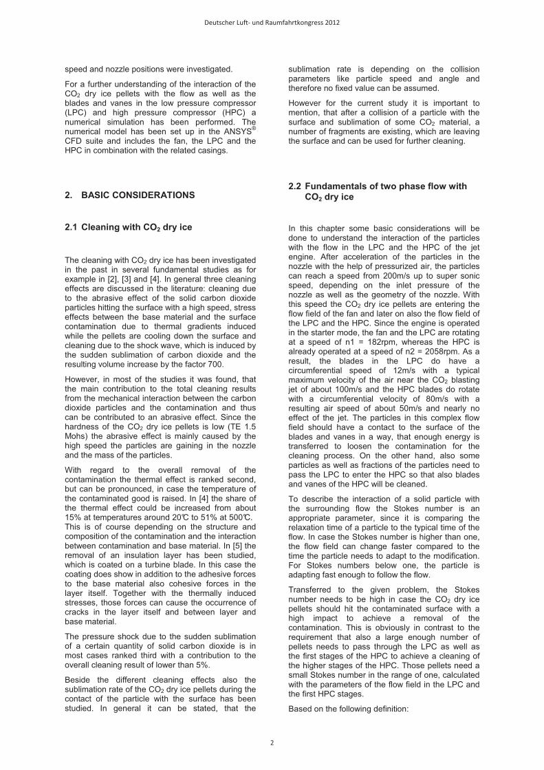
During operation the compressor of a jet engine is exposed to a high quantity of air and depending on the mission profile and the regions of operation of the aircraft also to a high variety of different sorts of contaminations coming along with the air. Due to the lack of information, which needs to be based on a wide study of different engines and operation profiles no general understanding of a typical contamination of the compressor of a civil aircraft jet engine is available. As one part of this study therefore first steps have been made to understand how and where the ingested material is deposited on the blades and vanes of the compressor. In figure 1 a photograph of a GE CF6-80 jet engine’s high pressure compressor rotor is depicted, which has been operated in a 747-400 aircraft. The aircraft has been in service to several destination mainly in the USA and China. Without further analysis it is very obvious, that the entrance, middle and outlet section do show different colors, which are a
reaction of the deposition of contaminations and the formation of oxides.
Figure 1: Typical contamination of a compressor.
When analyzing the layers of the different blades it has been found, that the thickness is increasing from the 5th stage of the compressor with about 10�m to maximum 33�m in stage thirteen. In general it has been observed, that the thickness is decreasing from the leading edge towards the trailing edge of the air foil. The element analysis of the layer clearly showed a decreasing weight percentage of Carbon black coming from the first stage of the compressor with nearly 40% on the blades and 55% on the vanes to about 5% in the 5th stage of the rotor and in the 7th stage of the stator. Also Oxygen showed a high weight percentage with slightly increasing numbers from the entrance area towards the exit of the high pressure compressor, with about 35% on the first rotor blades, respectively 25% on the first vanes to nearly 40% on the last stages of the compressor for both, blades and vanes. An other element, which has some significance, is Silicon. Again a slightly increasing distribution could be found coming from 5% in the 2nd stage and increasing up to 15% in the last stages with peaks up to 20% in the middle part of the compressor.
It is no yet clear, which significance those layers do have with regard to the aerodynamic behavior of the blade and vanes, thus decreasing the efficiency of the compressor. Also it needs to be understood, whether those layers can be completely removed by a cleaning process and on the other hand need to be completely removed to increase the efficiency of the compressor.
For a better understanding of the adhesion forces the contaminations have on the surface of the blade and vanes scratch tests have been performed. For this analysis an UST® 1000 from Innowep was applied, which has been used to get a profile of the adhesion forces along the airfoil. For the analysis a 90° diamond needle with a 5µm radius has been applied. The black layers of the blades and vanes in the entrance area, which are most likely Carbon based contaminations, started to be removable at a force of 4.6mN, whereas the contamination layers on the airfoils in the rear stages of the compressor with a higher content of oxides and Silicon needed higher forces of 40mN.
Deutscher Luft- und Raumfahrtkongress 2012
3
�� EXPERIMENTS�
�
3.1 Experimental set up
�
A test bench was constructed to study the cleaning with dry ice blasting in a jet engine. For the design of the test bench the following needs should be considered to control the primary variables of air velocity, particle velocity, particle size and the injection angle into a reasonable modern jet engine. The test bench should be large enough to allow the installation of a two shaft jet engine with a fan diameter of about 2.5m. To mimic the starter operation mode, it has been decided to use an electrical engine, which is able to motor the n2 shaft of the engine to the speed of the starter mode, which is typically in the range of 2000rpm and higher. To operate the dry ice blasting system a supply system for pressurized air needs to be available. The whole equipment should be installed in a dedicated test cell to reduce the influence of weather conditions during the operation.
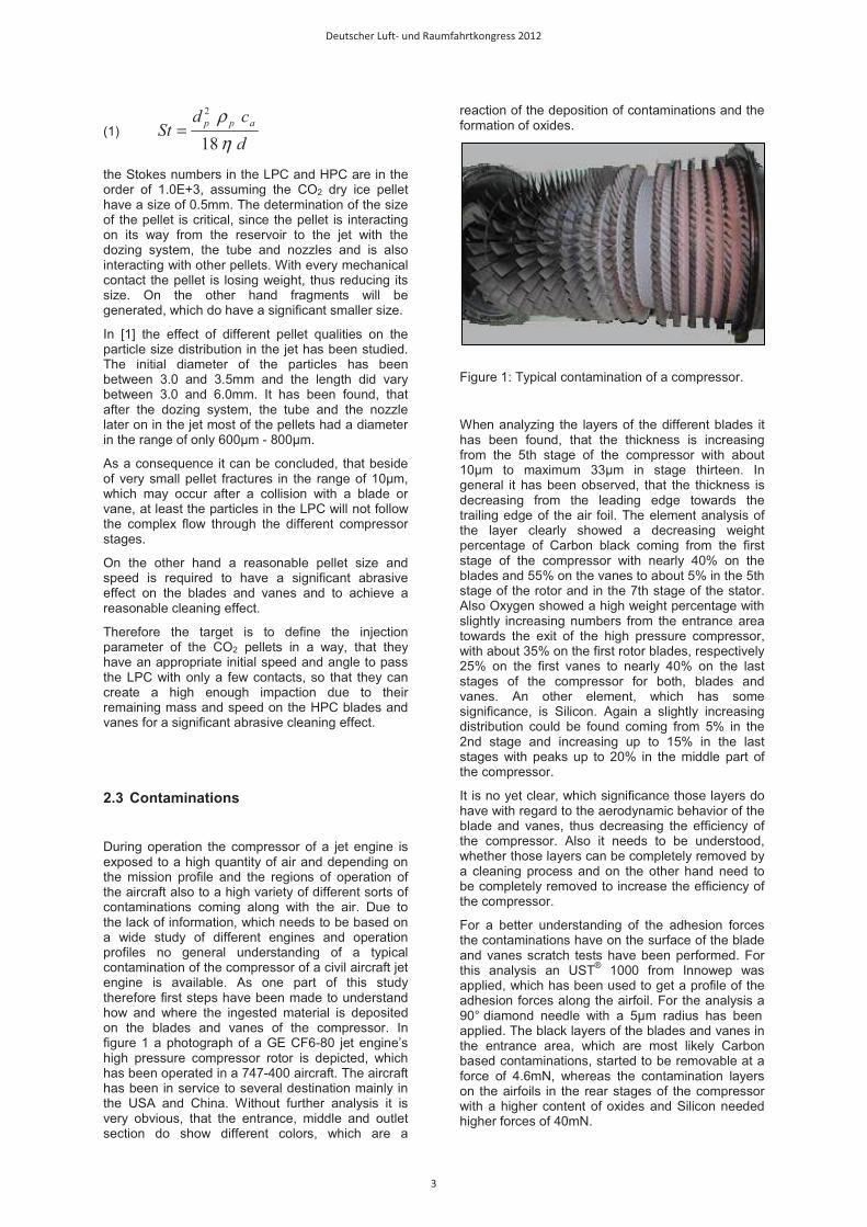
Figure 2 shows a photograph of the test bench, which fulfills these objectives. The engine is installed into a special rig, which is designed in a way that the fixation points, originally designed to carry the engine on the wing, can be used. In addition the test rig has been constructed to allow an easy access to the inner part of the HPC, which requires also a fast disassembly of the lower part of the case.
The motoring of the HPC shaft is done with an electrical engine, which has been connected via an additional shaft through the transfer gear box, The electrical engine is controlled by a frequency converter to allow the adjustment of the HPC shaft to speeds between 0rpm and the appropriate speed of the starter mode. To do so the maximum electrical power of 110kW is available, which results in a maximum n2 shaft speed of the currently installed GE CF6-50 engine of 2058rpm.
To operate the dry ice blasting equipment a system for pressurized air is required, which has been installed into the test cell. The main part of this system is an electrically driven compressor with an electrical power input of 55kW, which supplies 7.5m³/min air at a maximum pressure of 10bar. The compressed air is passing a dryer to reduce the humidity and is then fed to a reservoir. The reservoir serves as a buffer to equal out possible variations in the supply pressure level for the pellet dozing system and the nozzle. Depending on the actual test topic, the nozzle for the blasting is either positioned on a rack in the intake area of the jet engine or is fixed on a rotating mount on the fan spinner. Several nozzles have been tested, which varied in length, diameter ratio as well as cross section shape. In most cases a Laval type of nozzle was applied.
For the current investigations a GE CF6-50 engine is installed in the test rig. The engine has been modified in a way that the lower case of the HPC can be easily opened to allow for the artificial
contamination of the blades and vanes and inspection of the cleaning result. Also several openings have been drilled into the lower case, which are necessary to monitor the process parameters like temperatures, pressures and humidity during the dry ice blasting is activated. To measure the particle size distribution an IPAS sensor from Sequip® was utilized. As mentioned above, the transfer gear box was modified in a way that an additional drive shaft could be mounted from the rear, which allows the connection to the electrical engine. The original drive shaft to the gear box has been kept in its position, so that the lubrication system is working while the engine is motored to prevent for corrosion in the bearings. However, the fuel pump as well as the alternator was disassembled to reduce the required electrical power for motoring.
Figure 2: Test rig with GE CF6-50 engine, prepared for dry ice blasting test.
3.2 Experimental procedure
�
As part of the test preparation selected blades and vanes have been contaminated with an artificial coat to mimic the real pollution in a reproducible way. To do so, the lower casing of the HP compressor needs to be opened. Different types of artificial contaminations and paints have been tested to simulate the different types of real contaminations. One criterion for the selection of an appropriate artificial contamination has been the results of the scratch test as explained in chapter 3.3.
To mimic the Carbon black type of pollution with a relatively low adhesion a PTFE spray has been applied, which achieved in the scratch test an adhesion up to a normal force of 3.2mN. This spray is easy to apply and results in a nearly homogenous coating. Once an appropriate number of blades and vanes in the HP compressor have been contaminated photos were taken of each contaminated blade and vane to document the polluted status. Then the casing has been closed and the lubrication system has been connected with the lubricant pressure and scavenging pumps.
Deutscher Luft- und Raumfahrtkongress 2012
4
After activation of the compressed air system and the CO2 dry ice pellet dozing system as well as the data acquisition system the n2 shaft is ramped up to the targeted speed while the LP shaft speed is monitored. The moment the LP shaft speed has reached a stable value, the dozing system can be activated starting to inject the targeted pellet mass flow rate with an adjusted air pressure. All system parameters are kept constant for a defined time period or a defined total CO2 mass. After the targeted mass of dry ice pellets has been applied, the electrical engine and the dozing system are switched off and the shaft speeds are ramping down.
For a first visual inspection of the cleaning result a videoscope has been utilized and for the final documentation the lower HPC casing was opened and the status of the contaminated blades and vanes was documented with a photograph.
In several parameter studies the nozzle position, the shaft speeds as well as the air pressure and thus the velocity of the CO2 dry ice pellets has been varied to optimize the cleaning result. Also the effect of different pellet diameters and pellet processing types has been studied.
4. NUMERICAL SIMULATION
�
In addition to the experimental investigations, numerical studies have been performed to support the understanding of the complex interaction between the CO2 dry ice pellets, the air jet as well as the air flow in the compressor. With the help of the numerical model also parameter studies have been performed.
�4.1 Model preparation �
Since no CAD data has been available reverse engineering was necessary to create the geometric model of the fan, the LPC and HPC rotors and the related casings. With the geometric information a CATIA® CAD model was constructed, which has been uploaded with the ICEM® grid generator tool. The grid was build applying the Finite Volume Method, which is, given the targeted application, the preferable grid type. The grid has been set up section wise to allow the simulation of only the nozzle, the fan in combination with the LPC as well as the HPC. The HPC model itself is generated in a way, that the calculation of only the first three stages over 360°, the first seven stages over 180° and the whole 14 stages of the HP compressor over a 30°segment is possible. This does help to achieve a reasonable calculation time, since not always the modeling of all compressor parts is necessary.
The simulation has been performed within the ANSYS® CFD suite, which offers the necessary features for the simulation of a two phase flow in rotating grids.
To model the contact of the pellets with the blade and vanes as well as with the casing, the standard interaction tool of the ANSYS® CFD suite has been applied and the assumption has been taken, that 25% of the pellet mass is sublimating during the contact. This has been measured in a basic experimental set up for a row of three blades interacting with a jet of dry ice pellets and measuring the gaseous CO2 concentration in front and behind of the blades��
��
5. RESULTS
�5.1 Results of the CO2 dry ice blasting tests �5.1.1 Stationary nozzle �
At first pre tests have been performed without dry ice blasting and the data within the HP compressor were recorded. With increasing shaft speeds the pressure ratio is increasing and reaching its maximum value with 1.108, shortly after the n2 shaft speed achieved its target value of 2058rpm. Also the LP shaft speed is stable at 178 rpm once the HP shaft is rotating at his targeted level. Due to the thermal mass of the compressor and the casing, the temperatures increase relatively slow and reach nearly stable values earliest after 30 minutes of operation at target shaft speed. As a consequence of the increasing temperature level of the air and parts within the compressor, the relative humidity is reducing during operation.
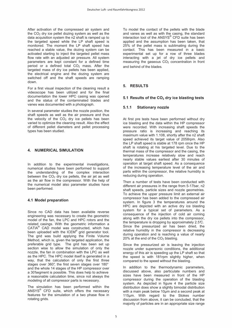
Then a number of tests have been conducted with different air pressures in the range from 5-17bar, n2 shaft speeds, particle sizes and nozzle geometries. To achieve the upper pressure limit an external air compressor has been added to the compressed air system. In figure 3 the temperatures around the HPC are depicted with an active dry ice blasting system for a typical set of parameters. As a consequence of the injection of cold air coming along with the dry ice pellets into the compressor, the temperature is dropping by approximately 2.5°C. Since the pressurized air has been dried, the relative humidity in the compressor is decreasing during operation and is reaching a value of nearly 20% at the end of the CO2 blasting.
Since the pressurized air is leaving the injection nozzle under supersonic conditions, the additional energy of this air is speeding up the LP shaft so that the speed is with 181rpm slightly higher, when compared to the speed without the blasting.
In addition to the thermodynamic parameters, discussed above, also particulate numbers and sizes have been measured in front of the HP compressor during the operation of the blasting system. As depicted in figure 4 the particle size distribution does show a slightly bimodal distribution with a main peak below 10�m and a second peak at 115�m. With regard to the Stokes number discussion from above, it can be concluded, that the majority of particles are in an appropriate size range
Deutscher Luft- und Raumfahrtkongress 2012
5
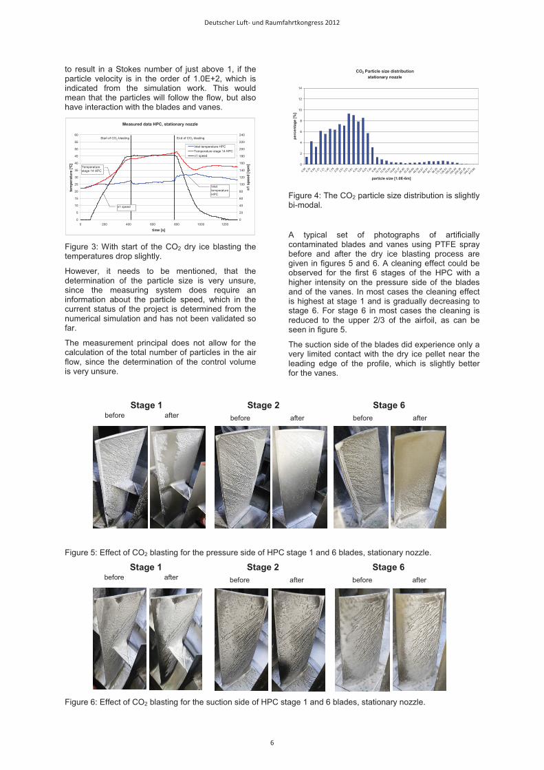
to result in a Stokes number of just above 1, if the particle velocity is in the order of 1.0E+2, which is indicated from the simulation work. This would mean that the particles will follow the flow, but also have interaction with the blades and vanes.
Measured data HPC, stationary nozzle
0
5
10
15
20
25
30
35
40
45
50
55
60
0 200 400 600 800 1000 1200
time [s]
tem
pera
ture
[°C
]
0
20
40
60
80
100
120
140
160
180
200
220
240
n1 s
peed
[rpm
]
Inlet temperature HPCTemperature stage 14 HPCn1 speed
Start of CO2 blasting End of CO2 blasting
Inlet temperature HPC
Temperature stage 14 HPC
n1 speed
Figure 3: With start of the CO2 dry ice blasting the temperatures drop slightly.
However, it needs to be mentioned, that the determination of the particle size is very unsure, since the measuring system does require an information about the particle speed, which in the current status of the project is determined from the numerical simulation and has not been validated so far.
The measurement principal does not allow for the calculation of the total number of particles in the air flow, since the determination of the control volume is very unsure.
CO2 Particle size distributionstationary nozzle
0
2
4
6
8
10
12
14
0,58
0,70
0,84
1,01
1,21
1,45
1,74
2,09
2,51
3,01
3,61
4,34
5,20
6,24
7,49
8,9910
,7912
,9515
,5418
,6422
,3726
,8532
,2238
,6646
,3955
,6766
,8180
,1796
,20
115,4
4
138,5
3
166,2
4
199,4
9
239,3
8
287,2
6
344,7
1
413,6
6
particle size [1.0E-6m]
perc
enta
ge [%
]
Figure 4: The CO2 particle size distribution is slightly bi-modal.
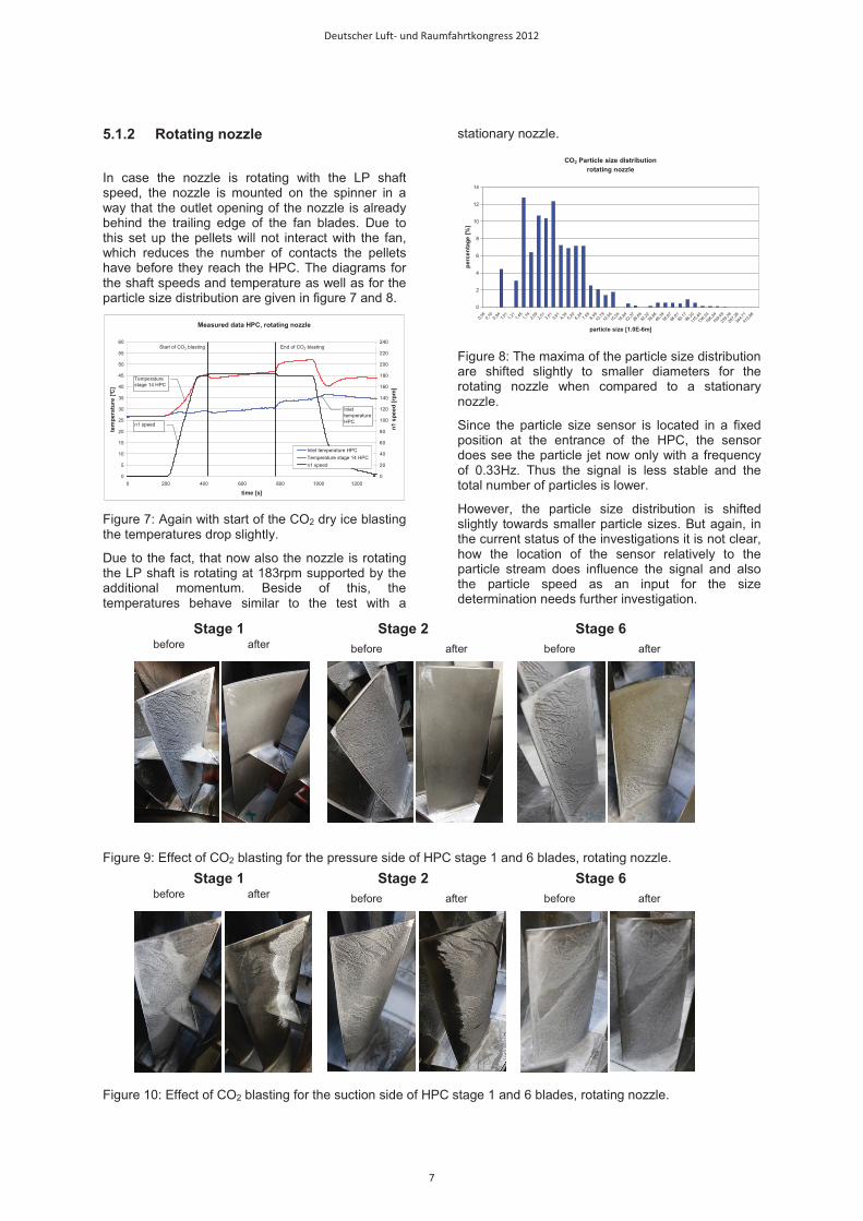
A typical set of photographs of artificially contaminated blades and vanes using PTFE spray before and after the dry ice blasting process are given in figures 5 and 6. A cleaning effect could be observed for the first 6 stages of the HPC with a higher intensity on the pressure side of the blades and of the vanes. In most cases the cleaning effect is highest at stage 1 and is gradually decreasing to stage 6. For stage 6 in most cases the cleaning is reduced to the upper 2/3 of the airfoil, as can be seen in figure 5.
The suction side of the blades did experience only a very limited contact with the dry ice pellet near the leading edge of the profile, which is slightly better for the vanes.
Figure 5: Effect of CO2 blasting for the pressure side of HPC stage 1 and 6 blades, stationary nozzle.
Figure 6: Effect of CO2 blasting for the suction side of HPC stage 1 and 6 blades, stationary nozzle.
Stage 2 Stage 6before afterbefore afterbefore after
Stage 1
Stage 2 Stage 6before afterbefore afterbefore after
Stage 1
Deutscher Luft- und Raumfahrtkongress 2012
6
5.1.2 Rotating nozzle �
In case the nozzle is rotating with the LP shaft speed, the nozzle is mounted on the spinner in a way that the outlet opening of the nozzle is already behind the trailing edge of the fan blades. Due to this set up the pellets will not interact with the fan, which reduces the number of contacts the pellets have before they reach the HPC. The diagrams for the shaft speeds and temperature as well as for the particle size distribution are given in figure 7 and 8.
Measured data HPC, rotating nozzle
0
5
10
15
20
25
30
35
40
45
50
55
60
0 200 400 600 800 1000 1200
time [s]
tem
pera
ture
[°C
]
0
20
40
60
80
100
120
140
160
180
200
220
240
n1 s
peed
[rpm
]
Inlet temperature HPCTemperature stage 14 HPCn1 speed
Start of CO2 blasting End of CO2 blasting
Inlet temperature HPC
Temperature stage 14 HPC
n1 speed
Figure 7: Again with start of the CO2 dry ice blasting the temperatures drop slightly.
Due to the fact, that now also the nozzle is rotating the LP shaft is rotating at 183rpm supported by the additional momentum. Beside of this, the temperatures behave similar to the test with a
stationary nozzle.
CO2 Particle size distributionrotating nozzle
0
2
4
6
8
10
12
14
0,58
0,70
0,84
1,01
1,21
1,45
1,74
2,09
2,51
3,01
3,61
4,34
5,20
6,24
7,49
8,9910
,7912
,9515
,5418
,6422
,3726
,8532
,2238
,6646
,3955
,6766
,8180
,1796
,20
115,4
4
138,5
3
166,2
4
199,4
9
239,3
8
287,2
6
344,7
1
413,6
6
particle size [1.0E-6m]
perc
enta
ge [%
]
Figure 8: The maxima of the particle size distribution are shifted slightly to smaller diameters for the rotating nozzle when compared to a stationary nozzle.
Since the particle size sensor is located in a fixed position at the entrance of the HPC, the sensor does see the particle jet now only with a frequency of 0.33Hz. Thus the signal is less stable and the total number of particles is lower.
However, the particle size distribution is shifted slightly towards smaller particle sizes. But again, in the current status of the investigations it is not clear, how the location of the sensor relatively to the particle stream does influence the signal and also the particle speed as an input for the size determination needs further investigation.
Figure 9: Effect of CO2 blasting for the pressure side of HPC stage 1 and 6 blades, rotating nozzle.
Figure 10: Effect of CO2 blasting for the suction side of HPC stage 1 and 6 blades, rotating nozzle.
Stage 2 Stage 6before afterbefore afterbefore after
Stage 1
Stage 2 Stage 6before afterbefore afterbefore after
Stage 1
Deutscher Luft- und Raumfahrtkongress 2012
7
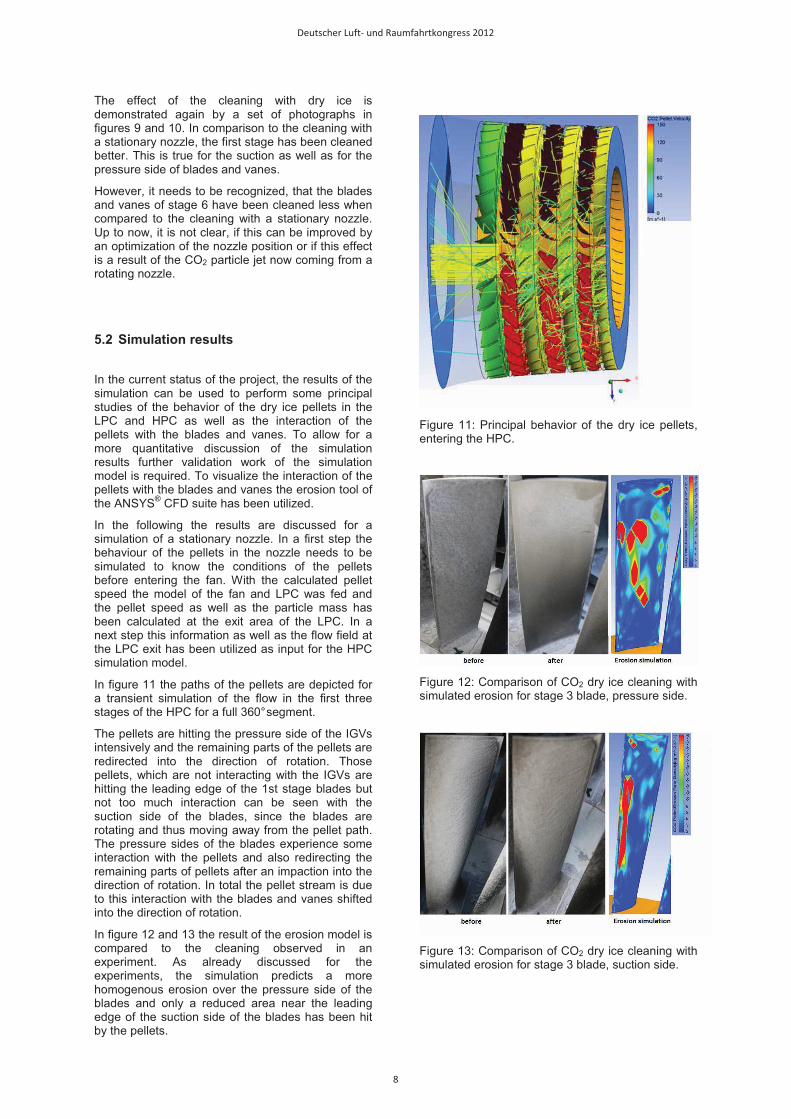
The effect of the cleaning with dry ice is demonstrated again by a set of photographs in figures 9 and 10. In comparison to the cleaning with a stationary nozzle, the first stage has been cleaned better. This is true for the suction as well as for the pressure side of blades and vanes.
However, it needs to be recognized, that the blades and vanes of stage 6 have been cleaned less when compared to the cleaning with a stationary nozzle. Up to now, it is not clear, if this can be improved by an optimization of the nozzle position or if this effect is a result of the CO2 particle jet now coming from a rotating nozzle.
5.2 Simulation results �
In the current status of the project, the results of the simulation can be used to perform some principal studies of the behavior of the dry ice pellets in the LPC and HPC as well as the interaction of the pellets with the blades and vanes. To allow for a more quantitative discussion of the simulation results further validation work of the simulation model is required. To visualize the interaction of the pellets with the blades and vanes the erosion tool of the ANSYS® CFD suite has been utilized.
In the following the results are discussed for a simulation of a stationary nozzle. In a first step the behaviour of the pellets in the nozzle needs to be simulated to know the conditions of the pellets before entering the fan. With the calculated pellet speed the model of the fan and LPC was fed and the pellet speed as well as the particle mass has been calculated at the exit area of the LPC. In a next step this information as well as the flow field at the LPC exit has been utilized as input for the HPC simulation model.
In figure 11 the paths of the pellets are depicted for a transient simulation of the flow in the first three stages of the HPC for a full 360° segment.
The pellets are hitting the pressure side of the IGVs intensively and the remaining parts of the pellets are redirected into the direction of rotation. Those pellets, which are not interacting with the IGVs are hitting the leading edge of the 1st stage blades but not too much interaction can be seen with the suction side of the blades, since the blades are rotating and thus moving away from the pellet path. The pressure sides of the blades experience some interaction with the pellets and also redirecting the remaining parts of pellets after an impaction into the direction of rotation. In total the pellet stream is due to this interaction with the blades and vanes shifted into the direction of rotation.
In figure 12 and 13 the result of the erosion model is compared to the cleaning observed in an experiment. As already discussed for the experiments, the simulation predicts a more homogenous erosion over the pressure side of the blades and only a reduced area near the leading edge of the suction side of the blades has been hit by the pellets.
Figure 11: Principal behavior of the dry ice pellets, entering the HPC.
Figure 12: Comparison of CO2 dry ice cleaning with simulated erosion for stage 3 blade, pressure side.
Figure 13: Comparison of CO2 dry ice cleaning with simulated erosion for stage 3 blade, suction side.
Deutscher Luft- und Raumfahrtkongress 2012
8
6. CONCLUSION
�
Experimental and numerical investigations have been performed to study the cleaning of the high pressure compressor of a jet engine under fully assembled conditions with CO2 dry ice pellets. From theoretical studies it is clear, that the chance a particle is moving through the fan and the low pressure compressor without any contact to the blades and vanes is very small. Only particles with a low speed and a small diameter will follow the flow and therefore can pass the low pressure compressor without losing significantly mass. Since those particles will have a reduced cleaning effect it is clear, that the parameters of the whole process need to be optimized in a way, that a compromise of particle size and speed is found, which guarantees a reasonable particle size and speed at the entrance of the high pressure compressor to achieve some cleaning.
A variety of parameter studies have been conducted with different air pressures, shaft speeds, particle sizes, particle mass flow rates and nozzle geometries and the resulting cleaning effects have been document. The results show that for both, a rotating as well as a stationary nozzle, conditions can be found, which deliver the necessary particle size and speed at the entrance of the high pressure compressor to achieve a cleaning of the blades and vanes up to stage 6 of the high pressure compressor.
However, a further optimization is necessary to improve the cleaning result in a way that especially the contamination on the suction side of the blades and vanes can be removed. Also the abrasive effect itself needs a further improvement to allow also the removal of contaminations with a stronger adhesion to the blade and vanes.
In addition to the experiments also simulation work has been performed, which helped to understand the particle behavior in the complex flow regime and also supported the design of the nozzles for the CO2blasting.
7. LITERATURE
[1] Grant, G., Tabakoff, W.: Erosion Prediction in
Turbomachinery Resulting from Environmental Solid Particles, Journal of Aircraft, Vol. 12, No. 5, May 1975
[2] Haberland, J.: Reinigen und Entschichten mit Trockeneisstrahlen – Grundlegende Untersuchungen des CO2-Strahlwerkzeuges und der Verfahrensweise, Ph. D. Thesis, Fortschrittsberichte VDI Reihe 2, Nr. 502, VDI Verlag Düsseldorf, 1999
[3] Redeker, C.: Abtragen mit Trockeneisstrahlen, Ph. D. Thesis, Fortschrittsberichte VDI Reihe 2, Nr. 639, VDI Verlag Düsseldorf, 2003
[4] Krieg, M.: Analyse der Effekte beim Trockeneisstrahle, Ph. D. Thesis, Fraunhofer IRB Verlag, 2008
[5] Krieg, M.: Möglichkeiten zur Bestimmung der Wirkmechanismen beim Trockeneisstrahlen, Publikationen Fraunhofer Institut
8. NOMENCLATURE
ca velocity of air
d typical length of flow field
dp diameter of particle
n1 shaft speed of the low pressure compressor
n2 shaft speed of the high pressure compressor
�d density of CO2 dry ice pellet
� dynamic viscosity of air
9. ACKNOWLEDGEMENT
The authors would like to thank the German BMWiand DLR for the support of this work.
Deutscher Luft- und Raumfahrtkongress 2012
9