Embed Size (px)
DESCRIPTION
http://www.dungs.com/fileadmin/media/Downloads/DBs_BMAs/252622.pdf?1290009960
Citation preview
1 … 12
M/C
D •
Editio
n 02
.10
• Nr.
252
622
Betriebs- und Montage-anleitung
Magnetventileinstufige BetriebsweiseTyp LV-DNennweiten Rp 2
Operation and assembly instructions
Solenoid valveSingle-stage operationModel LV-DNominal diameters Rp 2
Notice d’emploi et de montage
Électrovanne de sécuritéService à une allureType LV-DDiamètre nominal Rp 2
Istruzioni d’uso e di mon-taggio
Valvole elettromagnetiche monostadioTipo LV-DDiametri nominali Rp 2
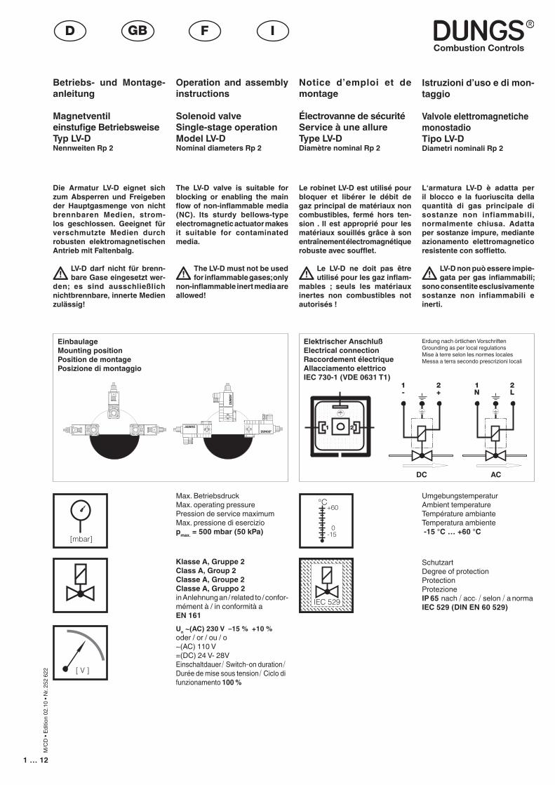
EinbaulageMounting positionPosition de montagePosizione di montaggio
Elektrischer AnschlußElectrical connectionRaccordement électriqueAllacciamento elettricoIEC 730-1 (VDE 0631 T1)
Erdung nach örtlichen VorschriftenGrounding as per local regulationsMise à terre selon les normes localesMessa a terra secondo prescrizioni locali
��
��
Max. Betriebsdruck Max. operating pressure Pression de service maximumMax. pressione di eserciziopmax. = 500 mbar (50 kPa)
Klasse A, Gruppe 2Class A, Group 2Classe A, Groupe 2Classe A, Gruppo 2in Anlehnung an / related to / confor-mément à / in conformità a EN 161Un ~(AC) 230 V –15 % +10 % oder / or / ou / o ~(AC) 110 V=(DC) 24 V- 28VEinschaltdauer/ Switch-on duration/ Durée de mise sous tension/ Ciclo di funzionamento 100 %
UmgebungstemperaturAmbient temperatureTempérature ambianteTemperatura ambiente -15 °C … +60 °C
Schutzart Degree of protection Protection Protezione IP 65 nach / acc. / selon / a norma IEC 529 (DIN EN 60 529)
[mbar]
[ V ]
°C
0
+60
-15
IEC 529IEC 529
� ��� �
��� ��� �
� ��� �
�� �� �����
�� ���� �
��� �� ���� �� ���� �� �� �� ��
��� �� �� ���
��
��
DC AC
��
Die Armatur LV-D eignet sich zum Absperren und Freigeben der Hauptgasmenge von nicht brennbaren Medien, strom-los geschlossen. Geeignet für verschmutzte Medien durch robusten elektromagnetischen Antrieb mit Faltenbalg.
LV-D darf nicht für brenn-bare Gase eingesetzt wer-
den; es sind ausschließlich nichtbrennbare, innerte Medien zulässig!
The LV-D valve is suitable for blocking or enabling the main flow of non-inflammable media (NC). Its sturdy bellows-type electromagnetic actuator makes it suitable for contaminated media.
The LV-D must not be used for inflammable gases; only
non-inflammable inert media are allowed!
Le robinet LV-D est utilisé pour bloquer et libérer le débit de gaz principal de matériaux non combustibles, fermé hors ten-sion . Il est approprié pour les matériaux souillés grâce à son entraînement électromagnétique robuste avec soufflet.
Le LV-D ne doit pas être utilisé pour les gaz inflam-
mables ; seuls les matériaux inertes non combustibles not autorisés !
L‘armatura LV-D è adatta per il blocco e la fuoriuscita della quantità di gas principale di sostanze non infiammabili, normalmente chiusa. Adatta per sostanze impure, mediante azionamento elettromagnetico resistente con soffietto.
LV-D non può essere impie-gata per gas infiammabili;
sono consentite esclusivamente sostanze non infiammabili e inerti.
2 … 12
M/C
D •
Editio
n 02
.10
• Nr.
252
622
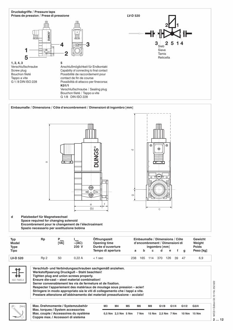
Einbaumaße / Dimensions / Côte d‘encombrement / Dimensioni di ingombro [mm]
Rp
Rp 2
ÖffnungszeitOpening timeDurée d’ouvertureTempo di apertura
< 1 sec
c
114
a
238
Einbaumaße / Dimensions / Côte d’encombrement / Dimensioni di
ingombro [mm]d
370
b
165
GewichtWeightPoidsPeso [kg]
6,9
TypModelTypeTipo LV-D 520
Pmax.[VA]
50
�
���� �
�
�
�
Imax.~(AC) 230 V
0,22 A
d Platzbedarf für Magnetwechsel Space required for changing solenoid Encombrement pour le changement de l’électroaimant Spazio necessario per sostituzione bobina
e
126
f
39
g
47
1, 2, 4, 3Verschlußschraube Screw plug Bouchon filetéTappo a vite G 1/8 DIN ISO 228
5Anschlußmöglichkeit für Endkontakt Capability of connecting to final contactPossibilité de raccordement pour contact de fin de coursePossibilità di attacco per finecorsa: K01/1Verschlußschraube / Sealing plugBouchon fileté / Tappo a vite G 1/8 DIN ISO 228
Druckabgriffe / Pressure tapsPrises de pression / Prese di pressione
�� ��
�
SiebSieveTamisReticella
222(5)
2 1
2 1
3 5 4
1
1 2
3 4
LV-D 520
Verschluß- und Verbindungsschrauben sachgemäß anziehen. Werkstoffpaarung Druckguß – Stahl beachten!Tighten plug and union screws properly. Ensure die-cast – steel material combination!Serrer convenablement les vis de fermeture et de fixation. Respecter l’appariement des matériaux de moulage sous pression – acier!Stringere in modo appropriato sia le viti di collegamento che i tappi a vite. Prestare attenzione all’abbinamento dei materiali pressofusione – acciaio!
ISO 7005-2
Max. Drehmomente / Systemzubehör M3 M4 M5 M6 M8 G1/8 G1/4 G1/2 G3/4Max. torques / System accessories Max. couple / Accessoires du système 0,5 Nm 2,5 Nm 5 Nm 7 Nm 15 Nm 2,5 Nm 7 Nm 10 Nm 15 NmCoppie max. / Accessori di sistema
[Nm]
18
19
SiebSieveTamisReticella
3 … 12
M/C
D •
Editio
n 02
.10
• Nr.
252
622
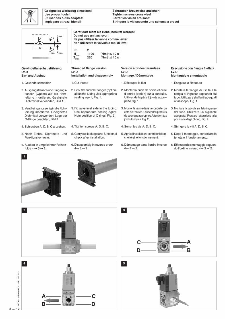
Gerät darf nicht als Hebel benutzt werden!Do not use unit as lever!Ne pas utiliser la vanne comme levier!Non utilizzare la valvola a mo’ di leva!
Rp 2 Mmax. 1100 [Nm] t ≤ 10 sTmax. 250 [Nm] t ≤ 10 s
Geeignetes Werkzeug einsetzen! Schrauben kreuzweise anziehen!Use proper tools! Tighten screws crosswise!Utiliser des outils adaptés! Serrer les vis en croisant!Impiegare attrezzi idonei! Stringere le viti secondo uno schema a croce!
SV
Mmax.
Tmax. Mmax.
1
3
CD
AB
AB
CD
2
GewindeflanschausführungLV-DEin- und Ausbau
1. Gewinde schneiden
2. Ausgangsflansch und Eingangs-flansch (Option) auf die Rohr-leitung montieren. Geeignete Dichtmittel verwenden, Bild 1.
3. Ventil eingangsseitig in die Rohr-leitung montieren. Geeignetes Dichmittel verwenden. Lage der O-Ringe beachten, Bild 2.
4. Schrauben A, D, B, C anziehen.
5. Nach Einbau Dichtheits- und Funktionskontrolle.
6. Ausbau in umgekehrter Reihen-folge 4 ➞ 3 ➞ 2.
Threaded flange versionLV-DInstallation and disassembly
1. Cut thread
2. Fit outlet and inlet flanges (option-al) on the tubing Use appropriate sealing agent, Fig. 1.
3. Fit valve inlet side in the tubing. Use appropriate sealing agent. Note position of O rings, Fig. 2.
4. Tighten screws A, D, B, C.
5. Carry out leakage and functional check after installation.
6. Disassembly in reverse order 4➞ 3 ➞ 2.
Version à brides taraudéesLV-DMontage / Démontage
1. Découper le filet
2. Monter la bride de sortie et celle d’entrée (option) sur la conduite. Utiliser de la pâte à joints appro-priée, fig. 1.
3. Monter la vanne dans la conduite, du côté de l’entrée. Utiliser des produits de bourrage appropriés. Attention aux joints toriques. Fig. 2.
4. Serrer les vis A, D, B, C.
5. Après l’installation, contrôler l’étan-chéité et le fonctionnement.
6. Démontage dans l’ordre inverse 4➞ 3 ➞ 2.
Esecuzione con flangia filettataLV-DMontaggio e smontaggio
1. Eseguire la filettatura
2. Montare la flangia di uscita e la flangia di ingresso (optional) sul tubo. Utilizzare sigillanti adeguati a tal scopo, Fig. 1.
3. Montare la valvola sul lato ingresso del tubo. Utilizzare un sigillante adeguato. Prestare attenzione alla posizione degli O-ring, Fig. 2.
4. Stringere le viti A, D, B, C.
5. Dopo il montaggio, controllare la tenuta e il funzionamento.
6. Effettuare lo smontaggio seguen-do l’ordine inverso 4➞ 3 ➞ 2.
54
4 … 12
M/C
D •
Editio
n 02
.10
• Nr.
252
622
IP 65OK
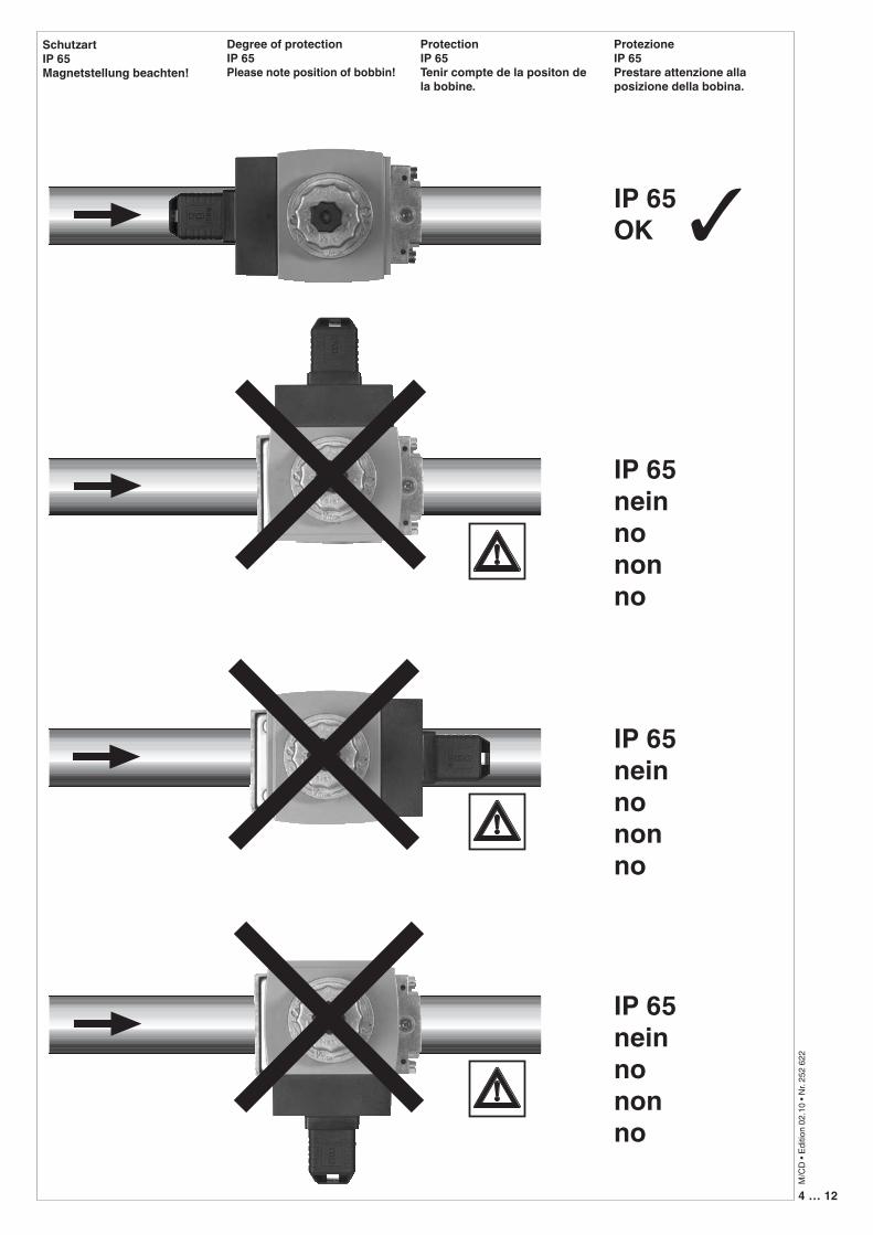
SchutzartIP 65Magnetstellung beachten!
Degree of protectionIP 65Please note position of bobbin!
ProtectionIP 65Tenir compte de la positon de la bobine.
ProtezioneIP 65Prestare attenzione alla posizione della bobina.
IP 65neinnononno
IP 65neinnononno
IP 65neinnononno
✓
5 … 12
M/C
D •
Editio
n 02
.10
• Nr.
252
622
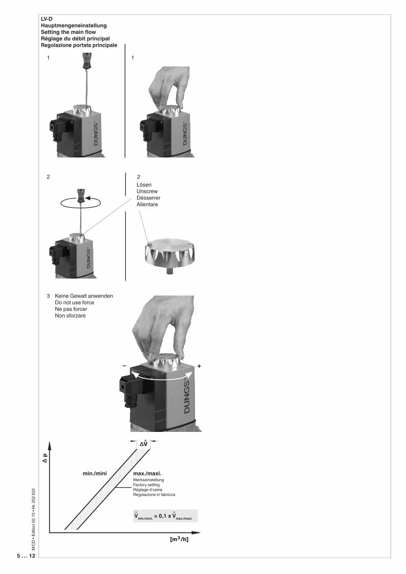
LV-DHauptmengeneinstellungSetting the main flowRéglage du débit principalRegolazione portata principale
1 1
LösenUnscrew DésserrerAllentare
2 2
3
[m /h]3
∆ p
∆V°
– +
Keine Gewalt anwendenDo not use forceNe pas forcerNon sforzare
min./mini max./maxi.WerkseinstellungFactory settingRéglage d‘usineRegolazione in fabricca
Vmin./mini. = 0,1 x Vmax./maxi.° °
6 … 12
M/C
D •
Editio
n 02
.10
• Nr.
252
622
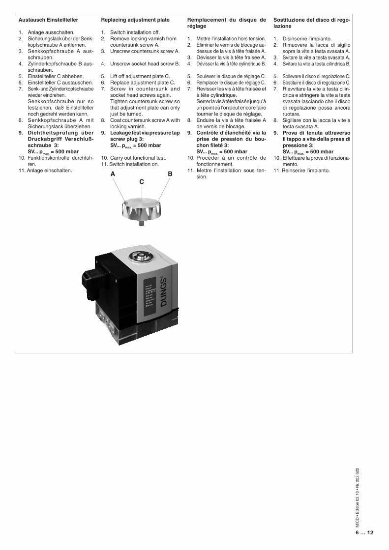
Austausch Einstellteller
1. Anlage ausschalten.2. Sicherungslack über der Senk-
kopfschraube A entfernen.3. Senkkopfschraube A aus-
schrauben.4. Zylinderkopfschraube B aus-
schrauben.5. Einstellteller C abheben.6. Einstellteller C austauschen.7. Senk- und Zylinderkopfschraube
wieder eindrehen. Senkkopfschraube nur so
festziehen, daß Einstellteller noch gedreht werden kann.
8. Senkkopfschraube A mit Sicherungslack überziehen.
9. Dichtheitsprüfung über Druckabgriff Verschluß-schraube 3:
SV... pmax. = 500 mbar10. Funktionskontrolle durchfüh-
ren.11. Anlage einschalten.
Replacing adjustment plate
1. Switch installation off.2. Remove locking varnish from countersunk screw A.3. Unscrew countersunk screw A.
4. Unscrew socket head screw B.
5. Lift off adjustment plate C.6. Replace adjustment plate C.7. Screw in countersunk and
socket head screws again. Tighten countersunk screw so
that adjustment plate can only just be turned.
8. Coat countersunk screw A with locking varnish.
9. Leakage test via pressure tap screw plug 3:
SV... pmax. = 500 mbar
10. Carry out functional test.11. Switch installation on.
Remplacement du disque de réglage
1. Mettre l’installation hors tension.2. Éliminer le vernis de blocage au-
dessus de la vis à tête fraisée A.3. Dévisser la vis à tête fraisée A.4. Dévisser la vis à tête cylindrique B.
5. Soulever le disque de réglage C. 6. Remplacer le disque de réglage C.7. Revisser les vis à tête fraisée et
à tête cylindrique. Serrer la vis à tête fraisée jusqu’à
un point où l’on peut encore faire tourner le disque de réglage.
8. Enduire la vis à tête fraisée A de vernis de blocage.
9. Contrôle d’étanchéité via la prise de pression du bou-chon fileté 3:
SV... pmax. = 500 mbar10. Procéder à un contrôle de
fonctionnement.11. Mettre l’installation sous ten-
sion.
Sostituzione del disco di rego-lazione
1. Disinserire l’impianto.2. Rimuovere la lacca di sigillo
sopra la vite a testa svasata A.3. Svitare la vite a testa svasata A.4. Svitare la vite a testa cilindrica B.
5. Sollevare il disco di regolazione C.6. Sostituire il disco di regolazione C.7. Riavvitare la vite a testa cilin-
drica e stringere la vite a testa svasata lasciando che il disco di regolazione possa ancora ruotare.
8. Sigillare con la lacca la vite a testa svasata A.
9. Prova di tenuta attraverso il tappo a vite della presa di pressione 3:
SV... pmax. = 500 mbar10. Effettuare la prova di funziona-
mento. 11. Reinserire l’impianto.
CA B
7 … 12
M/C
D •
Editio
n 02
.10
• Nr.
252
622
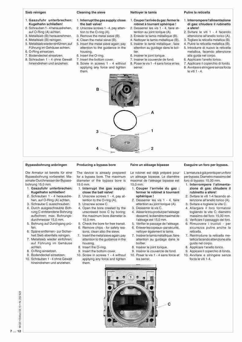
Sieb reinigen
1. Gaszufuhr unterbrechen: Kugelhahn schließen!
2. Schrauben 1 - 4 herausdrehen, auf O-Ring (A) achten.
3. Metallsieb (B) herausnehmen.4. Metallsieb (B) reinigen.5. Metallsieb wieder einführen; auf
Führung im Gehäuse achten.6. O-Ring einsetzen.7. Bodendeckel einsetzen.8. Schrauben 1 - 4 ohne Gewalt
hineindrehen und anziehen.
Bypassbohrung anbringen
Die Armatur ist bereits für eine Bypassbohrung vorbereitet. Ma-ximaler Durchmesser der Bypass-bohrung 15,0 mm. 1. Gaszufuhr unterbrechen:
Kugelhahn schließen! 2. Schrauben 1 - 4 herausdre-
hen, auf O-Ring (A) achten. 3. Schraube C ausschrauben. 4. Durch ausgeschraubte Boh-
rung C entstandene Bohrung aufbohren; max. Bohrungs-durchmesser 15,0 mm.
5. Bohrung auf Durchgang prü-fen.
6. Späne entfernen - zur Sicher-heit Sieb ebenfalls reinigen.
7. Metallsieb wieder einführen; auf Führung im Gehäuse achten.
8. O-Ring einsetzen. 9. Bodendeckel einsetzen.10. Schrauben 1 - 4 ohne Gewalt
hineindrehen und anziehen.
Cleaning the sieve
1. Interrupt the gas supply: close the ball valve!
2. Unscrew screws 1 - 4, pay atten-tion to the O-ring (A).
3. Remove the metal sieve (B).4. Clean the metal sieve (B).5. Insert the metal sieve again; pay
attention to the guidance in the housing.
6. Insert the O-ring.7. Insert the bottom cover.8. Screw in screws 1 - 4 without
applying any force and tighten them.
Nettoyer le tamis
1. Couper l‘arrivée du gaz : fermer le robinet à tournant sphérique !
2. Desserrer les vis 1 - 4, faire at-tention au joint torique (A).
3. Enlever le tamis métallique (B).4. Nettoyer le tamis métallique (B).5. Insérer le tamis métallique ; faire
attention au guidage dans le boî-tier.
6. Insérer le joint torique.7. Insérer le couvercle de fond.8. Poser le vis 1 - 4 sans force et les
serrer.
Pulire la reticella
1. Interrompere l‘alimentazione di gas: chiudere il rubinetto a sfere!
2. Svitare le viti 1 - 4 facendo attenzione all‘anello torico (A).
3. Togliere la reticella metallica (B).4. Pulire la reticella metallica (B).5. Introdurre di nuovo la reticella
metallica, facendo attenzione alla guida nel corpo.
6. Applicare l‘anello torico.7. Applicare il coperchio di fondo.8. Avvitare e stringere senza forza
le viti 1 - 4.
Eseguire un foro per bypass.
L‘armatura è già pronta per un foro per bypass. Diametro massimo del foro di bypass: 15,00 mm. 1. Interrompere l‘alimenta-
zione di gas: chiudere il rubinetto a sfere!
2. Svitare le viti 1-4 facendo at-tenzione all‘anello torico (A).
3. Svitare e togliere la vite C. 4. Allargare il foro formatosi
togliendo la vite C; diametro massimo del foro: 15,00 mm.
5. Verificare il passaggio del foro. 6. Rimuovere i trucioli - per
sicurezza pulire anche la reticella.
7. Reintrodurre la reticella me-tallica facendo attenzione alla guida nel corpo.
8. Applicare l‘anello torico. 9. Appicare il coperchio di fondo.10. Avvitare e stringere senza
forza le viti 1-4.
Producing a bypass bore
The device is already prepared for a bypass bore. The maximum diameter of the bypass bore is 15.0 mm. 1. Interrupt the gas supply:
close the ball valve! 2. Unscrew screws 1 - 4, pay at-
tention to the O-ring (A). 3. Unscrew screw C. 4. Open the bore created by the
unscrewed bore C by boring; the maximum bore diameter is 15.0 mm.
5. Check the bore for free transit. 6. Remove chips - for safety rea-
sons, clean also the sieve. 7. Insert the metal sieve again; pay
attention to the guidance in the housing.
8. Insert the O-ring. 9. Insert the bottom cover.10. Screw in screws 1 - 4 without
applying any force and tighten them.
Faire un alésage bipasse
Le robinet est déjà préparé pour un alésage bipasse. Le diamètre maximal de l‘alésage bipasse est 15,0 mm. 1. Couper l‘arrivée du gaz :
fermer le robinet à tournant sphérique !
2. Desserrer les vis 1 - 4, faire attention au joint torique (A).
3. Desserrer la vis C. 4. Aléser le trou produit par l‘alésage
desserré ; le diamètre maximal de l‘alésage est 15,0 mm.
5. Vérifier le passage de l‘alésage. 6. Enlever les copeaux - par sécurité,
nettoyer également le tamis. 7. Insérer le tamis métallique ; faire
attention au guidage dans le boîtier.
8. Insérer le joint torique. 9. Insérer le couvercle de fond.10. Poser le vis 1 - 4 sans force et
les serrer.
C
B
3
4
1
2
A
8 … 12
M/C
D •
Editio
n 02
.10
• Nr.
252
622
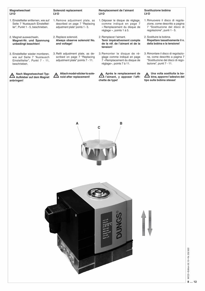
Magnetwechsel LV-D
1. Einstellteller entfernen, wie auf Seite 7 “Austausch Einstelltel-ler”, Punkt 1 - 5, beschrieben.
2. Magnet auswechseln. Magnet-Nr. und Spannung
unbedingt beachten!
3. Einstellteller wieder montieren, wie auf Seite 7 “Austausch Einstellteller”, Punkt 7 - 11, beschrieben.
Nach Magnetwechsel Typ-Aufkleber auf dem Magnet
anbringen!
Solenoid replacement LV-D
1. Remove adjustment plate, as described on page 7 “Replacing adjustment plate” points 1 - 5.
2. Replace solenoid. Always observe solenoid No.
and voltage!
3. Refit adjustment plate, as de-scribed on page 7 “Replacing adjustment plate” points 7 - 11.
Attach model-sticker to sole-noid after replacement!
Remplacement de l’aimantLV-D
1. Déposer le disque de réglage, comme indiqué en page 7 « Remplacement du disque de réglage », points 1 à 5.
2. Remplacer l’aimant. Tenir impérativement compte
de la réf. de l’aimant et de la tension!
3. Remonter le disque de ré-glage comme indiqué en page 7 «Remplacement du disque de réglage», points 7 à 11.
Après le remplacement de l’aimant, y apposer l’affi-
chette de type!
Sostituzione bobina LV-D
1. Rimuovere il disco di regola-zione, come descritto a pagina 7 “Sostituzione del disco di regolazione”, punti 1 - 5.
2. Sostituire la bobina. Rispettare tassativamente il n.
della bobina e la tensione!
3. Rimontare il disco di regolazio-ne, come descritto a pagina 7 “Sostituzione del disco di rego-lazione”, punti 7 - 11.
Una volta sostituita la bo-bina, apporre l’adesivo del
tipo sulla bobina stessa!
CA B
9 … 12
M/C
D •
Editio
n 02
.10
• Nr.
252
622
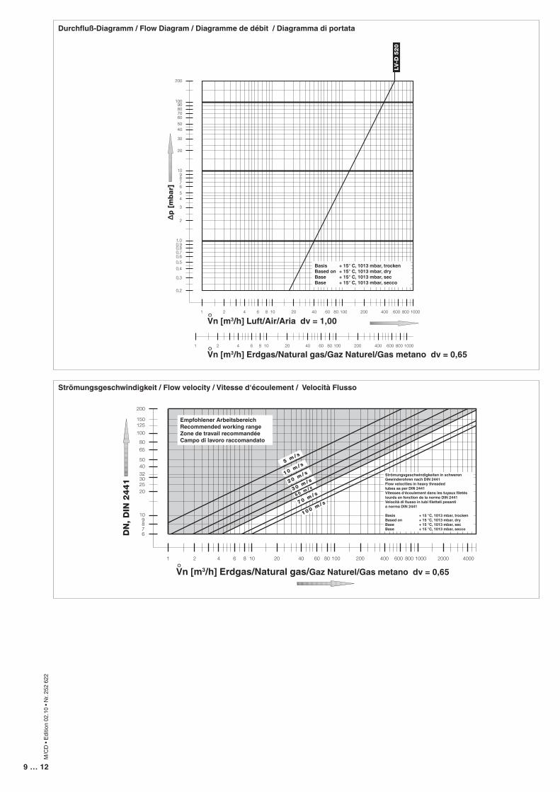
Durchfluß-Diagramm / Flow Diagram / Diagramme de débit / Diagramma di portata
678910
20
30
4050
200
100
65
80
1 2 4 6 8 10 20 40 60 80 100 200 400 600 800 1000 2000 4000
DN
, D
IN 2
441
150125
100 m/ s
5 m/ s
10 m/ s
30 m/ s
25
32
70 m/ s5 0 m
/ s20 m
/ s
Strömungsgeschwindigkeit / Flow velocity / Vitesse d‘écoulement / Velocità Flusso
0,2
0,3
0,4
0,50,60,70,8
1,00,9
2
3
45
678910
20
30
4050
200
100
60708090
1 2 4 6 8 10 20 40 60 80 100 200 400 600 800 1000
1 2 4 6 8 10 20 40 60 80 100 200 400 600 800 1000
∆p [
mbar]
LV
-D 5
20
Vn [m3/h] Erdgas/Natural gas/Gaz Naturel/Gas metano dv = 0,65
Vn [m3/h] Erdgas/Natural gas/Gaz Naturel/Gas metano dv = 0,65
Vn [m3/h] Luft/Air/Aria dv = 1,00
Basis + 15° C, 1013 mbar, trockenBased on + 15° C, 1013 mbar, dryBase + 15° C, 1013 mbar, sec Base + 15° C, 1013 mbar, secco
Empfohlener ArbeitsbereichRecommended working rangeZone de travail recommandéeCampo di lavoro raccomandato
Strömungsgeschwindigkeiten in schwerenGewinderohren nach DIN 2441Flow velocities in heavy threaded tubes as per DIN 2441Vitesses d‘écoulement dans les tuyaux filetés lourds en fonction de la norme DIN 2441Velocità di flusso in tubi filettati pesantia norma DIN 2441
Basis + 15 °C, 1013 mbar, trockenBased on + 15 °C, 1013 mbar, dryBase + 15 °C, 1013 mbar, secBase + 15 °C, 1013 mbar, secco
°
°
°
10 … 12
M/C
D •
Editio
n 02
.10
• Nr.
252
622
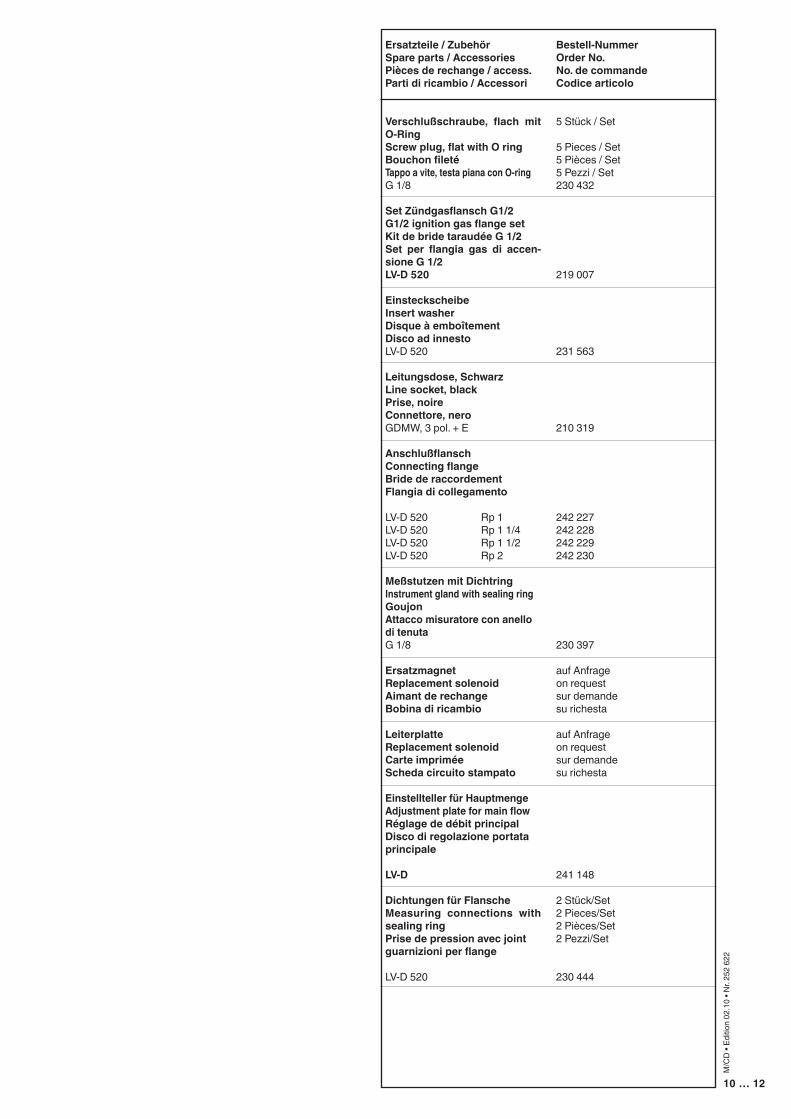
Ersatzteile / ZubehörSpare parts / AccessoriesPièces de rechange / access.Parti di ricambio / Accessori
Verschlußschraube, flach mit O-RingScrew plug, flat with O ringBouchon fileté Tappo a vite, testa piana con O-ringG 1/8
Set Zündgasflansch G1/2G1/2 ignition gas flange setKit de bride taraudée G 1/2 Set per flangia gas di accen-sione G 1/2LV-D 520
EinsteckscheibeInsert washerDisque à emboîtementDisco ad innestoLV-D 520
Leitungsdose, SchwarzLine socket, blackPrise, noireConnettore, neroGDMW, 3 pol. + E
AnschlußflanschConnecting flangeBride de raccordementFlangia di collegamento
LV-D 520 Rp 1LV-D 520 Rp 1 1/4LV-D 520 Rp 1 1/2LV-D 520 Rp 2
Meßstutzen mit DichtringInstrument gland with sealing ringGoujonAttacco misuratore con anello di tenutaG 1/8
ErsatzmagnetReplacement solenoidAimant de rechangeBobina di ricambio
LeiterplatteReplacement solenoidCarte impriméeScheda circuito stampato
Einstellteller für HauptmengeAdjustment plate for main flowRéglage de débit principalDisco di regolazione portata principale
LV-D
Dichtungen für FlanscheMeasuring connections with sealing ringPrise de pression avec jointguarnizioni per flange
LV-D 520
Bestell-NummerOrder No.No. de commandeCodice articolo
5 Stück / Set
5 Pieces / Set5 Pièces / Set5 Pezzi / Set230 432
219 007
231 563
210 319
242 227242 228242 229242 230
230 397
auf Anfrageon requestsur demandesu richesta
auf Anfrageon requestsur demandesu richesta
241 148
2 Stück/Set2 Pieces/Set2 Pièces/Set2 Pezzi/Set
230 444
11 … 12
M/C
D •
Editio
n 02
.10
• Nr.
252
622
Änderungen, die dem technischen Fortschritt dienen, vorbehalten / We reserve the right to make alterations in the course of technical improvement/ Sous réserve de modifications servant au progrès technologique / La società si riserva qualsiasi modifica tecnica e costruttiva
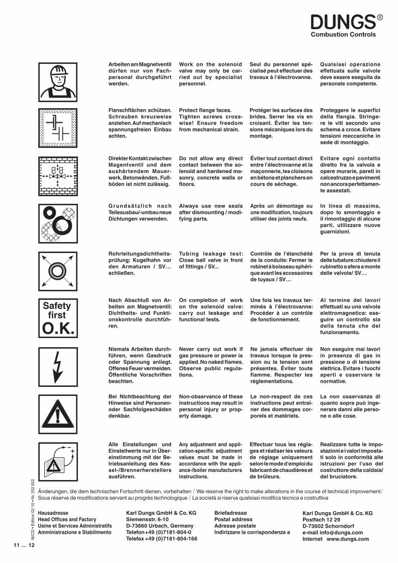
Arbeiten am Magnetventil dürfen nur von Fach-personal durchgeführt werden.
Flanschflächen schützen. Schrauben kreuzweise anziehen. Auf mechanisch spannungsfreien Einbau achten.
Direkter Kontakt zwischen Magentventil und dem aushärtendem Mauer-werk, Betonwänden, Fuß-böden ist nicht zulässig.
Grundsät z l ich nach Teileausbau/-umbau neue Dichtungen verwenden.
Rohrleitungsdichtheits-prüfung: Kugelhahn vor den Armaturen / SV… schließen.
Nach Abschluß von Ar-beiten am Magnetventil: Dichtheits- und Funkti-onskontrolle durchfüh-ren.
Niemals Arbeiten durch-führen, wenn Gasdruck oder Spannung anliegt. Offenes Feuer vermeiden. Öffentliche Vorschriften beachten.
Bei Nichtbeachtung der Hinweise sind Personen- oder Sachfolgeschäden denkbar.
Work on the solenoid valve may only be car-ried out by specialist personnel.
Protect flange faces. Tighten screws cross-wise! Ensure freedom from mechanical strain.
Do not allow any direct contact between the so-lenoid and hardened ma-sonry, concrete walls or floors.
Always use new seals after dismounting / modi-fying parts.
Tubing leakage test: Close ball valve in front of fittings / SV...
On completion of work on the solenoid valve: carry out leakage and functional tests.
Never carry out work if gas pressure or power is applied. No naked flames. Observe public regula-tions.
Non-observance of these instructions may result in personal injury or prop-erty damage.
Seul du personnel spé-cialisé peut effectuer des travaux à l’électrovanne.
Protéger les surfaces des brides. Serrer les vis en croisant. Éviter les ten-sions mécaniques lors du montage.
Éviter tout contact direct entre l’électrovanne et la maçonnerie, les cloisons en bétons et planchers en cours de séchage.
Après un démontage ou une modification, toujours utiliser des joints neufs.
Contrôle de l’étanchéité de la conduite: Fermer le robinet à boisseau sphéri-que avant les accessoires de tuyaux / SV…
Une fois les travaux ter-minés à l’électrovanne: Procéder à un contrôle de fonctionnement.
Ne jamais effectuer de travaux lorsque la pres-sion ou la tension sont présentes. Éviter toute flamme. Respecter les réglementations.
Le non-respect de ces instructions peut entraî-ner des dommages cor-porels et matériels.
Qualsiasi operazione effettuata sulle valvole deve essere eseguita da personale competente.
Proteggere le superfici della flangia. Stringe-re le viti secondo uno schema a croce. Evitare tensioni meccaniche in sede di montaggio.
Evitare ogni contatto diretto fra la valvola e opere murarie, pareti in calcestruzzo e pavimenti non ancora perfettamen-te assestati.
In linea di massima, dopo lo smontaggio e il rimontaggio di alcune parti, utilizzare nuove guarnizioni.
Per la prova di tenuta delle tubature: chiudere il rubinetto a sfera a monte delle valvole/ SV…
Al termine dei lavori effettuati su una valvola elettromagnetica: ese-guire un controllo sia della tenuta che del funzionamento.
Non eseguire mai lavori in presenza di gas in pressione o di tensione elettrica. Evitare i fuochi aperti e osservare le normative.
La non osservanza di quanto sopra può inge-nerare danni alle perso-ne o alle cose.
Safetyfirst
O.K.
Karl Dungs GmbH & Co. KGPostfach 12 29D-73602 Schorndorfe-mail [email protected] www.dungs.com
Karl Dungs GmbH & Co. KGSiemensstr. 6-10D-73660 Urbach, GermanyTelefon +49 (0)7181-804-0Telefax +49 (0)7181-804-166
HausadresseHead Offices and FactoryUsine et Services AdministratifsAmministrazione e Stabilimento
BriefadressePostal addressAdresse postaleIndirizzare la corrispondenza a
Alle Einstellungen und Einstellwerte nur in Über-einstimmung mit der Be-triebsanleitung des Kes-sel-/Brennerherstellers ausführen.
Any adjustment and appli-cation-specific adjustment values must be made in accordance with the appli-ance-/boiler manufacturers instructions.
Effectuer tous les régla-ges et réaliser les valeurs de réglage uniquement selon le mode d'emploi du fabricant de chaudières et de brûleurs.
Realizzare tutte le impo-stazioni e i valori imposta-ti solo in conformità alle istruzioni per l'uso del costruttore della caldaia/del bruciatore.
12 … 12
M/C
D •
Editio
n 02
.10
• Nr.
252
622
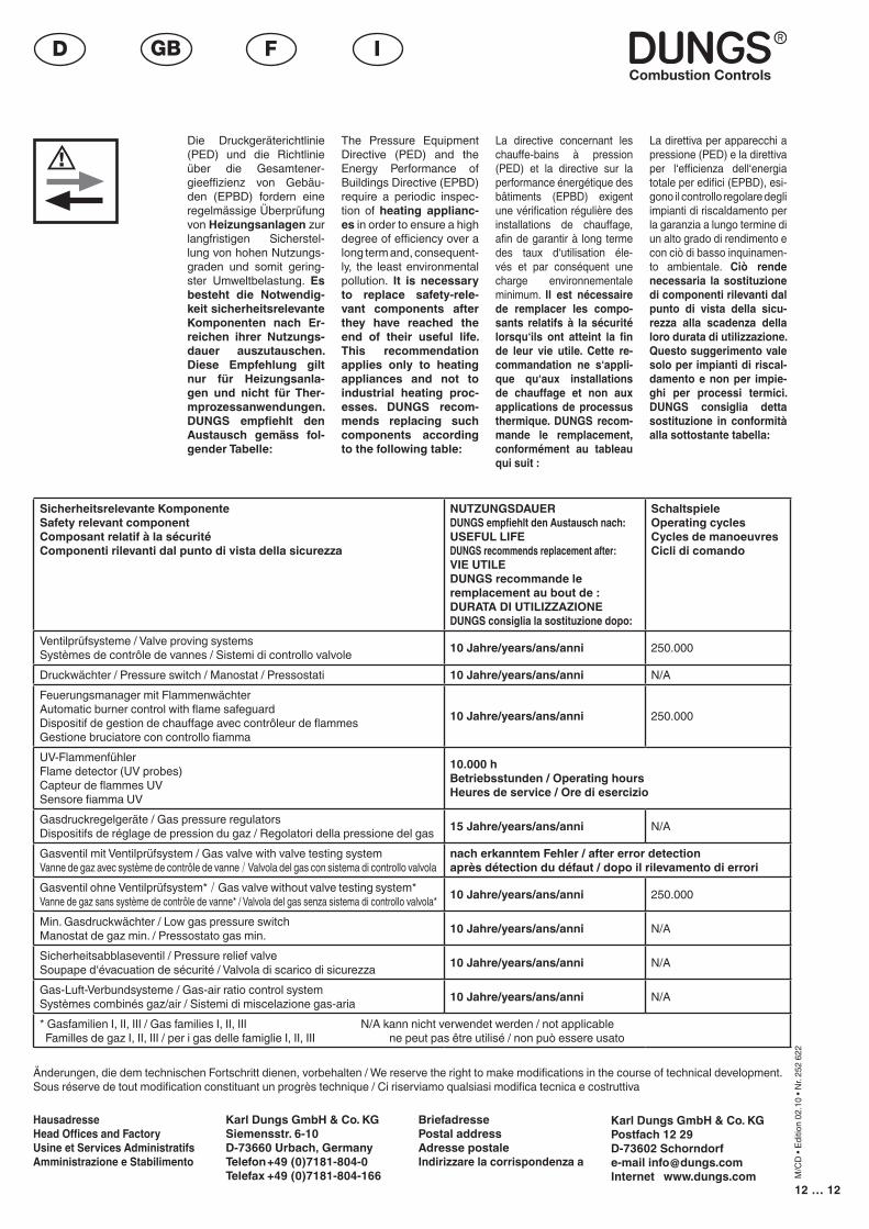
Die Druckgeräterichtlinie (PED) und die Richtlinie über die Gesamtener-gieeffizienz von Gebäu-den (EPBD) fordern eine regelmässige Überprüfung von Heizungsanlagen zur langfristigen Sicherstel-lung von hohen Nutzungs-graden und somit gering-ster Umweltbelastung. Es besteht die Notwendig-keit sicherheitsrelevante Komponenten nach Er-reichen ihrer Nutzungs-dauer auszutauschen. Diese Empfehlung gilt nur für Heizungsanla-gen und nicht für Ther-mprozessanwendungen. DUNGS empfiehlt den Austausch gemäss fol-gender Tabelle:
The Pressure Equipment Directive (PED) and the Energy Performance of Buildings Directive (EPBD) require a periodic inspec-tion of heating applianc-es in order to ensure a high degree of efficiency over a long term and, consequent-ly, the least environmental pollution. It is necessary to replace safety-rele-vant components after they have reached the end of their useful life. This recommendation applies only to heating appliances and not to industrial heating proc-esses. DUNGS recom-mends replacing such components according to the following table:
La directive concernant les chauffe-bains à pression (PED) et la directive sur la performance énergétique des bâtiments (EPBD) exigent une vérification régulière des installations de chauffage, afin de garantir à long terme des taux d‘utilisation éle-vés et par conséquent une charge environnementale minimum. Il est nécessaire de remplacer les compo-sants relatifs à la sécurité lorsqu‘ils ont atteint la fin de leur vie utile. Cette re-commandation ne s‘appli-que qu‘aux installations de chauffage et non aux applications de processus thermique. DUNGS recom-mande le remplacement, conformément au tableau qui suit :
La direttiva per apparecchi a pressione (PED) e la direttiva per l‘efficienza dell‘energia totale per edifici (EPBD), esi-gono il controllo regolare degli impianti di riscaldamento per la garanzia a lungo termine di un alto grado di rendimento e con ciò di basso inquinamen-to ambientale. Ciò rende necessaria la sostituzione di componenti rilevanti dal punto di vista della sicu-rezza alla scadenza della loro durata di utilizzazione. Questo suggerimento vale solo per impianti di riscal-damento e non per impie-ghi per processi termici. DUNGS consiglia detta sostituzione in conformità alla sottostante tabella:
Sicherheitsrelevante KomponenteSafety relevant componentComposant relatif à la sécuritéComponenti rilevanti dal punto di vista della sicurezza
NUTZUNGSDAUERDUNGS empfiehlt den Austausch nach:USEFUL LIFEDUNGS recommends replacement after:VIE UTILEDUNGS recommande le remplacement au bout de :DURATA DI UTILIZZAZIONEDUNGS consiglia la sostituzione dopo:
SchaltspieleOperating cyclesCycles de manoeuvresCicli di comando
Ventilprüfsysteme / Valve proving systems Systèmes de contrôle de vannes / Sistemi di controllo valvole 10 Jahre/years/ans/anni 250.000
Druckwächter / Pressure switch / Manostat / Pressostati 10 Jahre/years/ans/anni N/AFeuerungsmanager mit FlammenwächterAutomatic burner control with flame safeguardDispositif de gestion de chauffage avec contrôleur de flammesGestione bruciatore con controllo fiamma
10 Jahre/years/ans/anni 250.000
UV-FlammenfühlerFlame detector (UV probes)Capteur de flammes UVSensore fiamma UV
10.000 h Betriebsstunden / Operating hoursHeures de service / Ore di esercizio
Gasdruckregelgeräte / Gas pressure regulatorsDispositifs de réglage de pression du gaz / Regolatori della pressione del gas 15 Jahre/years/ans/anni N/A
Gasventil mit Ventilprüfsystem / Gas valve with valve testing systemVanne de gaz avec système de contrôle de vanne / Valvola del gas con sistema di controllo valvola
nach erkanntem Fehler / after error detectionaprès détection du défaut / dopo il rilevamento di errori
Gasventil ohne Ventilprüfsystem* / Gas valve without valve testing system*Vanne de gaz sans système de contrôle de vanne* / Valvola del gas senza sistema di controllo valvola* 10 Jahre/years/ans/anni 250.000
Min. Gasdruckwächter / Low gas pressure switchManostat de gaz min. / Pressostato gas min. 10 Jahre/years/ans/anni N/A
Sicherheitsabblaseventil / Pressure relief valveSoupape d‘évacuation de sécurité / Valvola di scarico di sicurezza 10 Jahre/years/ans/anni N/A
Gas-Luft-Verbundsysteme / Gas-air ratio control systemSystèmes combinés gaz/air / Sistemi di miscelazione gas-aria 10 Jahre/years/ans/anni N/A
* Gasfamilien I, II, III / Gas families I, II, III N/A kann nicht verwendet werden / not applicable Familles de gaz I, II, III / per i gas delle famiglie I, II, III ne peut pas être utilisé / non può essere usato
� ��� �
��� ��� �
� ��� �
�� �� �����
�� ���� �
��� �� ���� �� ���� �� �� �� ��
��� �� �� ���
Änderungen, die dem technischen Fortschritt dienen, vorbehalten / We reserve the right to make modifications in the course of technical development.Sous réserve de tout modification constituant un progrès technique / Ci riserviamo qualsiasi modifica tecnica e costruttiva
Karl Dungs GmbH & Co. KGPostfach 12 29D-73602 Schorndorfe-mail [email protected] www.dungs.com
Karl Dungs GmbH & Co. KGSiemensstr. 6-10D-73660 Urbach, GermanyTelefon +49 (0)7181-804-0Telefax +49 (0)7181-804-166
HausadresseHead Offices and FactoryUsine et Services AdministratifsAmministrazione e Stabilimento
BriefadressePostal addressAdresse postaleIndirizzare la corrispondenza a