Embed Size (px)
Citation preview
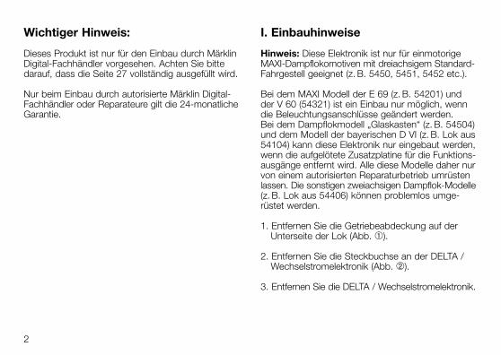
60955
Wichtiger Hinweis:
Dieses Produkt ist nur für den Einbau durch MärklinDigital-Fachhändler vorgesehen. Achten Sie bittedarauf, dass die Seite 27 vollständig ausgefüllt wird.
Nur beim Einbau durch autorisierte Märklin Digital-Fachhändler oder Reparateure gilt die 24-monatlicheGarantie.
I. Einbauhinweise
Hinweis: Diese Elektronik ist nur für einmotorigeMAXI-Dampflokomotiven mit dreiachsigem Standard-Fahrgestell geeignet (z. B. 5450, 5451, 5452 etc.).
Bei dem MAXI Modell der E 69 (z. B. 54201) undder V 60 (54321) ist ein Einbau nur möglich, wenndie Beleuchtungsanschlüsse geändert werden. Bei dem Dampflokmodell „Glaskasten“ (z. B. 54504)und dem Modell der bayerischen D VI (z. B. Lok aus54104) kann diese Elektronik nur eingebaut werden,wenn die aufgelötete Zusatzplatine für die Funktions-ausgänge entfernt wird. Alle diese Modelle daher nurvon einem autorisierten Reparaturbetrieb umrüstenlassen. Die sonstigen zweiachsigen Dampflok-Modelle(z. B. Lok aus 54406) können problemlos umge-rüstet werden.
1. Entfernen Sie die Getriebeabdeckung auf derUnterseite der Lok (Abb. ➀).
2. Entfernen Sie die Steckbuchse an der DELTA /Wechselstromelektronik (Abb. ➁).
3. Entfernen Sie die DELTA / Wechselstromelektronik.
2

3
➀ ➁
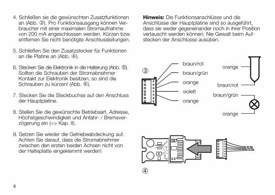
4. Schließen sie die gewünschten Zusatzfunktionenan (Abb. ➂). Pro Funktionsausgang können Ver-braucher mit einer maximalen Stromaufnahmevon 200 mA angeschlossen werden. Kürzen bzw.entfernen Sie nicht benötigte Anschlussleitungen.
5. Schließen Sie den Zusatzstecker für Funktionenan die Platine an (Abb. ➃).
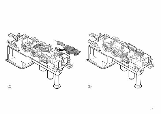
6. Stecken Sie die Elektronik in die Halterung (Abb. ➄).Sollten die Schrauben der Stromabnehmer Kontakt zur Elektronik besitzen, so sind dieSchrauben zu kürzen! (Abb. ➅).
7. Stecken Sie die Steckbuchse auf den Anschlussder Hauptplatine.
8. Stellen Sie die gewünschte Betriebsart, Adresse,Höchstgeschwindigkeit und Anfahr- / Bremsver-zögerung ein (=> Kap. II).
9. Setzen Sie wieder die Getriebeabdeckung auf.Achten Sie darauf, dass die Stromabnehmer zwischen den ersten beiden Achsen nicht von der Halteplatte eingeklemmt werden!
Hinweis: Die Funktionsanschlüsse und dieAnschlüsse der Hauptplatine sind so ausgeführt,dass sie weder gegeneinander noch in ihrer Positionvertauscht werden können. Nie Gewalt beim Auf-stecken der Anschlüsse ausüben.
4
➃
braun/rot
braun/grün
orange
violett
orange
orange
braun/rot
braun/grün
orange
➂
5
➄ ➅
II. Bedienungshinweise
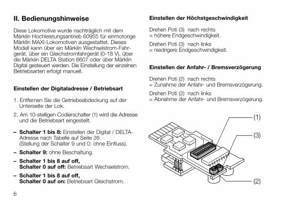
Diese Lokomotive wurde nachträglich mit dem Märklin Hochleistungsantrieb 60955 für einmotorigeMärklin MAXI-Lokomotiven ausgestattet. DiesesModell kann über ein Märklin Wechselstrom-Fahr-gerät, über ein Gleichstromfahrgerät (0-18 V), überdie Märklin DELTA Station 6607 oder über MärklinDigital gesteuert werden. Die Einstellung der einzelnenBetriebsarten erfolgt manuell.
Einstellen der Digitaladresse / Betriebsart
1. Entfernen Sie die Getriebeabdeckung auf derUnterseite der Lok.
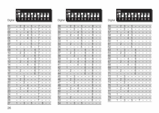
2. Am 10-stelligen Codierschalter (1) wird die Adresseund die Betriebsart eingestellt.
– Schalter 1 bis 8: Einstellen der Digital / DELTA-Adresse nach Tabelle auf Seite 26(Stellung der Schalter 9 und 0: ohne Einfluss).
– Schalter 9: ohne Beschaltung.
– Schalter 1 bis 8 auf off, Schalter 0 auf off: Betriebsart Wechselstrom.
– Schalter 1 bis 8 auf off, Schalter 0 auf on: Betriebsart Gleichstrom.
Einstellen der Höchstgeschwindigkeit
Drehen Poti (3) nach rechts = höhere Endgeschwindigkeit.
Drehen Poti (3) nach links = niedrigere Endgeschwindigkeit.
Einstellen der Anfahr- / Bremsverzögerung
Drehen Poti (2) nach rechts = Zunahme der Anfahr- und Bremsverzögerung.
Drehen Poti (2) nach links = Abnahme der Anfahr- und Bremsverzögerung.
6
(1)
(2)
(3)
Schalten der Funktionsausgänge
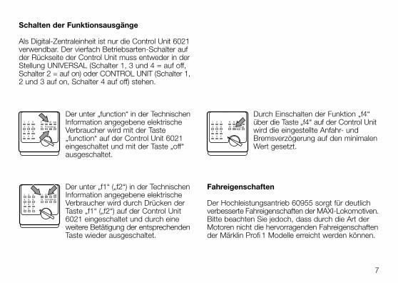
Als Digital-Zentraleinheit ist nur die Control Unit 6021verwendbar. Der vierfach Betriebsarten-Schalter aufder Rückseite der Control Unit muss entweder in derStellung UNIVERSAL (Schalter 1, 3 und 4 = auf off,Schalter 2 = auf on) oder CONTROL UNIT (Schalter 1,2 und 3 auf on, Schalter 4 auf off) stehen.
Der unter „function“ in der TechnischenInformation angegebene elektrischeVerbraucher wird mit der Taste „function“ auf der Control Unit 6021eingeschaltet und mit der Taste „off“ausgeschaltet.
Der unter „f1“ („f2“) in der TechnischenInformation angegebene elektrischeVerbraucher wird durch Drücken derTaste „f1“ („f2“) auf der Control Unit6021 eingeschaltet und durch eineweitere Betätigung der entsprechendenTaste wieder ausgeschaltet.
Durch Einschalten der Funktion „f4“über die Taste „f4“ auf der Control Unitwird die eingestellte Anfahr- undBremsverzögerung auf den minimalenWert gesetzt.
Fahreigenschaften
Der Hochleistungsantrieb 60955 sorgt für deutlichverbesserte Fahreigenschaften der MAXI-Lokomotiven.Bitte beachten Sie jedoch, dass durch die Art derMotoren nicht die hervorragenden Fahreigenschaftender Märklin Profi 1 Modelle erreicht werden können.
7
L 0 F
7 8 9
4 5 6 f3 f4 go
1 2 3 f1 f2 off stop
function
L 0 F
7 8 9
4 5 6 f3 f4 go
1 2 3 f1 f2 off stop
function
L 0 F
7 8 9
4 5 6 f3 f4 go
1 2 3 f1 f2 off stop
function
Important:
This product is designed for installation by authorizedMärklin digital dealers only. Please make sure thatthe technical information (Page 27) is complete.
The 24 month warranty is valid only when the instal-lation is done by authorized Märklin digital dealers or service stations.
I. Instructions for Installation
Important: This electronic circuit is only suitable forsingle-motor MAXI steam locomotives with the three-axle standard frame (example: 5450, 5451, 5452, etc.).
It can be installed in the MAXI model of the E 69(example: 54201) and the V 60 (54321) when theconnections for the headlights are changed. Thiselectronic circuit can be installed in the “Glaskasten”steam locomotive model (example: 54504) and themodel of the Bavarian D VI (example: locomotivefrom the 54104 set) only when the auxiliary circuitboard for the function outputs soldered to the maincircuit board is removed. All of these models shouldbe converted only by an authorized repair center.The other two-axle steam locomotive models(example: locomotive from the 54406 set) can beconverted without any problem.
1. Remove the drive gear cover plate on the bottomof the locomotive (ill. ➀).
2. Remove the connector socket on the DELTA /alternating current electronic circuit (ill. ➁).
3. Remove the DELTA / alternating current electroniccircuit.
8

9
➀ ➁
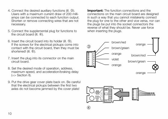
4. Connect the desired auxiliary functions (ill. ➂).Users with a maximum current draw of 200 milli-amps can be connected to each function output.Shorten or remove connecting wires that are notnecessary.
5. Connect the supplemental plug for functions tothe circuit board (ill. ➃).
6. Insert the circuit board into its holder (ill. ➄). If the screws for the electrical pickups come intocontact with the circuit board, then they must beshortened! (ill. ➅).
7. Insert the plug into its connector on the main circuit board.
8. Set the desired mode of operation, address,maximum speed, and acceleration/braking delay(=> Section II).
9. Put the drive gear cover plate back on. Be carefulthat the electrical pickups between the first twoaxles do not become jammed by the cover plate!
Important: The function connections and the connections on the main circuit board are designedin such a way that you cannot mistakenly connectthe plug for one to the other and vice versa, nor canthe plugs be put into the socket connectors thereverse of what they should be. Never use forcewhen inserting the plugs.
10
➃
brown/red
brown/green
orange
violet
orange
orange
brown/red
brown/green
orange
➂

11
➄ ➅
II. Operating Information
This locomotive has been retrofitted with the 60955Märklin high-efficiency propulsion for single motorMärklin MAXI locomotives. This model can be con-trolled with a Märklin alternating current train controltransformer, a direct current power pack (0-18 volts),the Märklin 6607 DELTA Station, or with MärklinDigital. The settings for individual operating modesare done manually.
Setting the Digital Address / Mode of Operation
1. Remove the drive gear cover plate on the bottomof the locomotive.
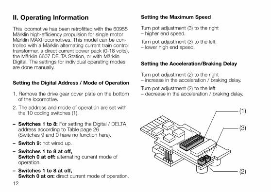
2. The address and mode of operation are set withthe 10 coding switches (1).
– Switches 1 to 8: For setting the Digital / DELTAaddress according to Table page 26(Switches 9 and 0 have no function here).
– Switch 9: not wired up.
– Switches 1 to 8 at off, Switch 0 at off: alternating current mode of operation.
– Switches 1 to 8 at off, Switch 0 at on: direct current mode of operation.
Setting the Maximum Speed
Turn pot adjustment (3) to the right – higher end speed.
Turn pot adjustment (3) to the left – lower high end speed.
Setting the Acceleration/Braking Delay
Turn pot adjustment (2) to the right – increase in the acceleration / braking delay.
Turn pot adjustment (2) to the left – decrease in the acceleration / braking delay.
12
(1)
(2)
(3)
Turning the Functions Outputs On and Off
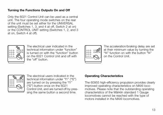
Only the 6021 Control Unit can be used as a centralunit. The four operating mode switches on the rearof the unit must be set either for the UNIVERSALsetting (Switches 1, 3, and 4 at off, Switch 2 at on)or the CONTROL UNIT setting (Switches 1, 2, and 3at on, Switch 4 at off).
The electrical user indicated in thetechnical information under “function”is turned on with the “function” buttonon the 6021 Control Unit and off withthe “off” button.
The electrical users indicated in thetechnical information under “f1” (“f2”)are turned on by pressing the “f1”(“f2”) button once on the 6021 Control Unit, and are turned off by pres-sing the same button a second time.
The acceleration/braking delay are setat their minimum value by turning the“f4” function on with the button “f4”on the Control Unit.
Operating Characteristics
The 60955 high-efficiency propulsion provides clearlyimproved operating characteristics on MAXI loco-motives. Please note that the outstanding operatingcharacteristics of the Märklin standard 1 Gaugelocomotives cannot be reached with the type ofmotors installed in the MAXI locomotives.
13
L 0 F
7 8 9
4 5 6 f3 f4 go
1 2 3 f1 f2 off stop
function
L 0 F
7 8 9
4 5 6 f3 f4 go
1 2 3 f1 f2 off stop
function
L 0 F
7 8 9
4 5 6 f3 f4 go
1 2 3 f1 f2 off stop
function
Remarque importante:
Ce produit ne peut être installé que par un détaillant-spécialiste Märklin. Vérifiez si les informations tech-niques sont bien complètes (page 27).
La garantie Märklin de 24 mois n’est valable quesi le produit est installé par un détaillant-spécialisteou un réparateur Märklin Digital agréé.
I. Remarque sur le montage:
Remarque: Cette électronique ne convient quepour les locomotives à vapeur MAXI à un moteur etchâssis à 3 essieux standard (par ex. 5450, 5451,5452, etc.).
Avec les locomotives MAXI E 69 (par ex. 54201) et V 60 (54321), le montage n’est possible que si lesconnexions pour les feux sont modifiées. Avec lalocomotive à vapeur „Glaskasten“ (par ex. 54504) etla locomotive bavaroise D VI (par ex. loco de 54104),cette électronique ne peut être installée que si laplatine complémentaire pour sorties de fonction estenlevée. Tous ces modèles réduits ne peuvent êtremodifiés que par un atelier de réparation agréé. Les autres modèles de locomotives à vapeur à deuxessieux (par ex. loco de 54406) peuvent être modi-fiés sans problèmes.
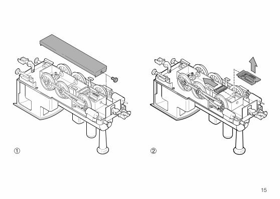
1. Enlevez le couvercle du mécanisme d’engrenagessitué sous la locomotive (fig. ➀).
2. Enlevez la douille de l’électronique DELTA-courantalternatif (fig. ➁).
3. Enlevez l’électronique DELTA-courant alternatif.
14
15
➀ ➁
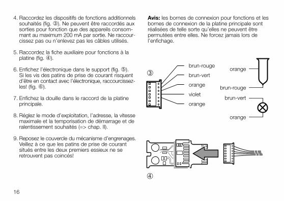
4. Raccordez les dispositifs de fonctions additionnelssouhaités (fig. ➂). Ne peuvent être raccordés auxsorties pour fonction que des appareils consom-mant au maximum 200 mA par sortie. Ne raccour-cissez pas ou n’enlevez pas les câbles utilisés.
5. Raccordez la fiche auxiliaire pour fonctions à laplatine (fig. ➃).
6. Enfichez l’électronique dans le support (fig. ➄). Si les vis des patins de prise de courant risquentd’être en contact avec l’électronique, raccourcissez-les! (fig. ➅).
7. Enfichez la douille dans le raccord de la platineprincipale.
8. Réglez le mode d’exploitation, l’adresse, la vitessemaximale et la temporisation de démarrage et deralentissement souhaités (=> chap. II).
9. Reposez le couvercle du mécanisme d’engrenages.Veillez à ce que les patins de prise de courantsitués entre les deux premiers essieux ne seretrouvent pas coincés!
Avis: les bornes de connexion pour fonctions et lesbornes de connexion de la platine principale sontréalisées de telle sorte qu’elles ne peuvent être permutées entre elles. Ne forcez jamais lors de l’enfichage.
16
➃
brun-rouge
brun-vert
orange
violet
orange
orange
brun-rouge
brun-vert
orange
➂

17
➄ ➅
II. Remarques sur l’utilisation
Cette locomotive a été équipée ultérieurement d’unmoteur 60955 à hautes performances prévu pour leslocomotives MAXI Märklin à un seul moteur. Ce modèlepeut être commandé soit par un régulateur Märklincourant alternatif, soit par un régulateur Märklin cou-rant continu (0-18 V), soit par une station DELTA 6607,soit par une alimentation Digital Märklin. Le réglagedu mode d’exploitation se fait manuellement.
Réglage de l’adresse digitale / du mode d’exploitation
1. Enlevez le couvercle du mécanisme d’engrenagessitué sous la locomotive.
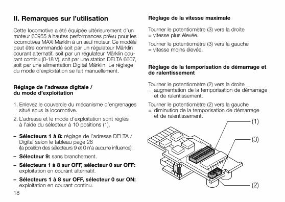
2. L’adresse et le mode d’exploitation sont réglés à l’aide du sélecteur à 10 positions (1).
– Sélecteurs 1 à 8: réglage de l’adresse DELTA /Digital selon le tableau page 26 (la position des sélecteurs 9 et 0 n’a aucune influence).
– Sélecteur 9: sans branchement.
– Sélecteurs 1 à 8 sur OFF, sélecteur 0 sur OFF:exploitation en courant alternatif.
– Sélecteurs 1 à 8 sur OFF, sélecteur 0 sur ON:exploitation en courant continu.
Réglage de la vitesse maximale
Tourner le potentiomètre (3) vers la droite = vitesse plus élevée.
Tourner le potentiomètre (3) vers la gauche = vitesse moins élevée.
Réglage de la temporisation de démarrage etde ralentissement
Tourner le potentiomètre (2) vers la droite = augmentation de la temporisation de démarrage
et de ralentissement.
Tourner le potentiomètre (2) vers la gauche = diminution de la temporisation de démarrage
et de ralentissement.
18
(1)
(2)
(3)
Commutation des sorties pour fonctions
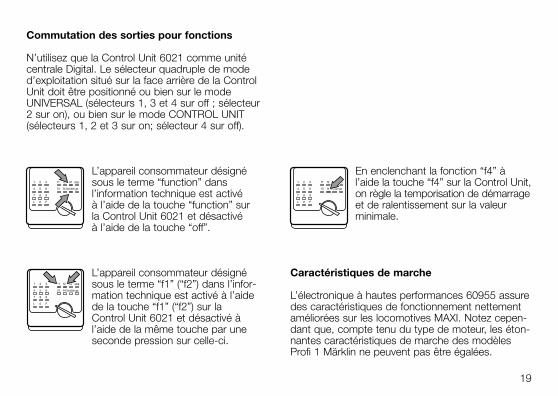
N’utilisez que la Control Unit 6021 comme unitécentrale Digital. Le sélecteur quadruple de moded’exploitation situé sur la face arrière de la ControlUnit doit être positionné ou bien sur le modeUNIVERSAL (sélecteurs 1, 3 et 4 sur off ; sélecteur2 sur on), ou bien sur le mode CONTROL UNIT(sélecteurs 1, 2 et 3 sur on; sélecteur 4 sur off).
L’appareil consommateur désignésous le terme “function” dans l’information technique est activé à l’aide de la touche “function” sur la Control Unit 6021 et désactivé à l’aide de la touche “off”.
L’appareil consommateur désignésous le terme “f1” (“f2”) dans l’infor-mation technique est activé à l’aidede la touche “f1” (“f2”) sur la Control Unit 6021 et désactivé à l’aide de la même touche par uneseconde pression sur celle-ci.
En enclenchant la fonction “f4” à l’aide la touche “f4” sur la Control Unit,on règle la temporisation de démarrageet de ralentissement sur la valeurminimale.
Caractéristiques de marche
L’électronique à hautes performances 60955 assuredes caractéristiques de fonctionnement nettementaméliorées sur les locomotives MAXI. Notez cepen-dant que, compte tenu du type de moteur, les éton-nantes caractéristiques de marche des modèlesProfi 1 Märklin ne peuvent pas être égalées.
19
L 0 F
7 8 9
4 5 6 f3 f4 go
1 2 3 f1 f2 off stop
function
L 0 F
7 8 9
4 5 6 f3 f4 go
1 2 3 f1 f2 off stop
function
L 0 F
7 8 9
4 5 6 f3 f4 go
1 2 3 f1 f2 off stop
function
Belangrijke opmerking:
Dit produkt is alleen bestemd voor inbouw door de Märklin-digitaal winkelier. Let er op a.u.b., dat pagina 27 volledig ingevuld wordt.
Alleen bij inbouw door de geautoriseerde Märklin-digitaal winkelier of het Märklin service centrum isde Märklin garantie van 24 maanden geldig.
I. Inbouwaanwijzingen
Opmerking: deze elektronicamodule is bestemdvoor één motorige MAXI-stoomlocomtieven met eendrie-assig, standaard drijfwerk (bijv. 5450, 5451,5452 e.d.) Bij het MAXI model van de E 69 (bijv. 54201)en van de V 60 (54321) is het inbouwen alleenmogelijk als de verlichtingsaansluitingen gewijzigdworden. Bij het stoomlocomotiefmodel “Glaskasten”(bijv. 54504) en het model van de Beierse D VI (bijv. de loc uit 54104) kan de elektronicamodulealleen ingebouwd worden als de extra printplaatvoor de functie uitgangen verwijderd word. Al dezemodellen dienen daarom alleen door een geautori-seerd reparatiebedrijf omgebouwd te worden. De andere twee-assige stoomlocomotief modellen(bijv. loc uit 54406) kunnen zonder probleem omge-bouwd worden.
1. Verwijder de afdekplaat tussen de wielen aan de onderzijde van de loc (fig. ➀).
2. Neem de stekker van de DELTA- / wisselstroom-elektronica los (fig. ➁).
3. Verwijder de DELTA- / wisselstroom-elektronica.
20

21
➀ ➁
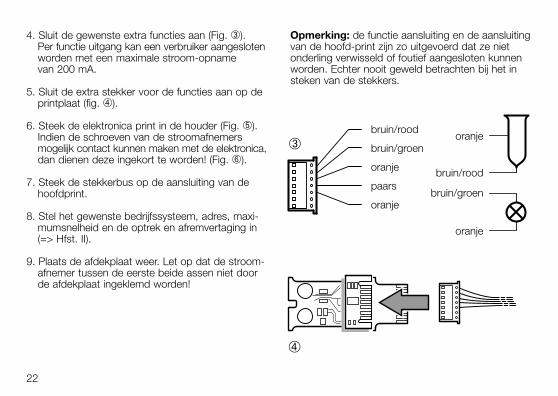
4. Sluit de gewenste extra functies aan (Fig. ➂). Per functie uitgang kan een verbruiker aangeslotenworden met een maximale stroom-opname van 200 mA.
5. Sluit de extra stekker voor de functies aan op deprintplaat (fig. ➃).
6. Steek de elektronica print in de houder (Fig. ➄).Indien de schroeven van de stroomafnemersmogelijk contact kunnen maken met de elektronica,dan dienen deze ingekort te worden! (Fig. ➅).
7. Steek de stekkerbus op de aansluiting van dehoofdprint.
8. Stel het gewenste bedrijfssysteem, adres, maxi-mumsnelheid en de optrek en afremvertaging in(=> Hfst. II).
9. Plaats de afdekplaat weer. Let op dat de stroom-afnemer tussen de eerste beide assen niet doorde afdekplaat ingeklemd worden!
Opmerking: de functie aansluiting en de aansluitingvan de hoofd-print zijn zo uitgevoerd dat ze nietonderling verwisseld of foutief aangesloten kunnenworden. Echter nooit geweld betrachten bij het insteken van de stekkers.
22
➃
bruin/rood
bruin/groen
oranje
paars
oranje
oranje
bruin/rood
bruin/groen
oranje
➂

23
➄ ➅
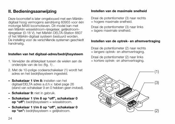
II. Bedieningsaanwijzing
Deze locomotief is later omgebouwd met een Märklin-digitaal hoog vermogens aandrijving 60955 voor éénmotorige MAXI locomotieven. Dit model kan meteen Märklin wisselstroom-rijregelaar, gelijkstroom-rijregelaar (0-18 V), het Märklin DELTA-Station 6607of het Märklin-digitaal systeem bestuurd worden. De instelling voor de verschillende systemen geschiedthandmatig.
Instellen van het digitaal-adres/bedrijfssysteem
1. Verwijder de afdekplaat tussen de wielen aan deonderzijde van de loc (fig. 1) .
2. Met de 10-polige codeerschakelaar (1) wordt hetadres en het bedrijfssysteem ingesteld.
– Schakelaar 1 t/m 8: instellen van hetdigitaal/DELTA adres a.d.h.v. tabel page 26 (stand van schakelaar 9 en 0 hebben geen invloed).
– Schakelaar 9: niet in gebruik.
– Schakelaar 1 t/m 8 op “off”, schakelaar 0op “off”: bedrijfssysteem = wisselstroom.
– Schakelaar 1 t/m 8 op “off”, schakelaar 0op “on”: bedrijfssysteem = gelijkstroom.
Instellen van de maximale snelheid
Draai de potentiometer (3) naar rechts = hogere maximale snelheid.
Draai de potentiometer (3) naar links = lagere maximale snelheid.
Instellen van de optrek- en afremvertraging
Draai de potentiometer (2) naar rechts = langere optrek- en afremvertraging.
Draai de potentiometer (2) naar links = kortere optrek- en afremvertraging.
24
(1)
(2)
(3)
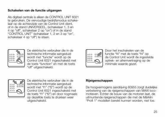
Schakelen van de functie uitgangen
Als digitaal centrale is alleen de CONTROL UNIT 6021te gebruiken. De viervoudige bedrijfsmodus schake-laar op de achterzijde van de Control Unit dient, of in de stand UNIVERSEEL, (schakelaar 1, 3 en 4 op “off”, schakelaar 2 op “on”) of in de stand“CONTROL UNIT” (schakelaar 1, 2 en 3 op “on”, schakelaar 4 op “off”) te staan.
De elektrische verbruiker die in detechnische informatie aangeduidwordt met “functie” wordt op de Control Unit 6021 ingeschakeld metde toets “function” en met de toets“off” uitgeschakeld.
De elektrische verbruiker die in detechnische informatie aangeduidwordt met “f1” (“f2”) wordt op deControl Unit 6021 ingeschakeld metde toets “f1” (“f2”) en door nogmaalsop dezelfde toets te drukken weer uitgeschakeld.
Door het inschakelen van de functie “f4” met de toets “f4” op de Control Unit wordt de ingesteldeoptrek- en afremvertraging op deminimale waarde gezet.
Rijeigenschappen
De hoogvermogens aandrijving 60955 zorgt duidelijkeverbetering van de rijeigenschappen van MAXI loco-motieven. Echter de bouw van de motoren laat, deuitmuntende rijeigenschappen die met de Märklin“Profi 1” modellen bereikt kunnen worden, niet toe.
25
L 0 F
7 8 9
4 5 6 f3 f4 go
1 2 3 f1 f2 off stop
function
L 0 F
7 8 9
4 5 6 f3 f4 go
1 2 3 f1 f2 off stop
function
L 0 F
7 8 9
4 5 6 f3 f4 go
1 2 3 f1 f2 off stop
function
26
Digital Digital Digital
01 – 2 3 – 5 – 7 – – –02 – – 3 – 5 – 7 – – –03 1 – – 4 5 – 7 – – –04 – 2 – 4 5 – 7 – – –05 – – – 4 5 – 7 – – –06 1 – – – 5 – 7 – – –07 – 2 – – 5 – 7 – – –08 – – – – 5 – 7 – – –09 1 – 3 – – 6 7 – – –10 – 2 3 – – 6 7 – – –11 – – 3 – – 6 7 – – –12 1 – – 4 – 6 7 – – –13 – 2 – 4 – 6 7 – – –14 – – – 4 – 6 7 – – –15 1 – – – – 6 7 – – –16 – 2 – – – 6 7 – – –17 – – – – – 6 7 – – –18 1 – 3 – – – 7 – – –19 – 2 3 – – – 7 – – –20 – – 3 – – – 7 – – –21 1 – – 4 – – 7 – – –22 – 2 – 4 – – 7 – – –23 – – – 4 – – 7 – – –24 1 – – – – – 7 – – –25 – 2 – – – – 7 – – –26 – – – – – – 7 – – –27 1 – 3 – 5 – – 8 – –
28 – 2 3 – 5 – – 8 – –29 – – 3 – 5 – – 8 – –30 1 – – 4 5 – – 8 – –31 – 2 – 4 5 – – 8 – –32 – – – 4 5 – – 8 – –33 1 – – – 5 – – 8 – –34 – 2 – – 5 – – 8 – –35 – – – – 5 – – 8 – –36 1 – 3 – – 6 – 8 – –37 – 2 3 – – 6 – 8 – –38 – – 3 – – 6 – 8 – –39 1 – – 4 – 6 – 8 – –40 – 2 – 4 – 6 – 8 – –41 – – – 4 – 6 – 8 – –42 1 – – – – 6 – 8 – –43 – 2 – – – 6 – 8 – –44 – – – – – 6 – 8 – –45 1 – 3 – – – – 8 – –46 – 2 3 – – – – 8 – –47 – – 3 – – – – 8 – –48 1 – – 4 – – – 8 – –49 – 2 – 4 – – – 8 – –50 – – – 4 – – – 8 – –51 1 – – – – – – 8 – –52 – 2 – – – – – 8 – –53 – – – – – – – 8 – –54 1 – 3 – 5 – – – – –
55 – 2 3 – 5 – – – – –56 – – 3 – 5 – – – – –57 1 – – 4 5 – – – – –58 – 2 – 4 5 – – – – –59 – – – 4 5 – – – – –60 1 – – – 5 – – – – –61 – 2 – – 5 – – – – –62 – – – – 5 – – – – –63 1 – 3 – – 6 – – – –64 – 2 3 – – 6 – – – –65 – – 3 – – 6 – – – –66 1 – – 4 – 6 – – – –67 – 2 – 4 – 6 – – – –68 – – – 4 – 6 – – – –69 1 – – – – 6 – – – –70 – 2 – – – 6 – – – –71 – – – – – 6 – – – –72 1 – 3 – – – – – – –73 – 2 3 – – – – – – –74 – – 3 – – – – – – –75 1 – – 4 – – – – – –76 – 2 – 4 – – – – – –77 – – – 4 – – – – – –78 1 – – – – – – – – –79 – 2 – – – – – – – –80 1 – 3 – 5 – 7 – – –
27
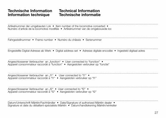
Technische Information Technical InformationInformation technique Technische informatie
...................................................................................................................................................................................................Artikelnummer der umgebauten Lok • Item number of the locomotive converted •Numéro d'article de la locomotive modifiée • Artikelnummer van de omgebouwde loc
...................................................................................................................................................................................................Fahrgestellnummer • Frame number • Numéro du châssis • Serienummer
...................................................................................................................................................................................................Eingestellte Digital-Adresse ab Werk • Digital address set • Adresse digitale encodée • Ingesteld digitaal adres
..................................................................................................................................................................................................Angeschlossener Verbraucher an „function“ • User connected to “function” •Appareil consommateur raccordé à “function” • Aangesloten verbruiker op “functie”
..................................................................................................................................................................................................Angeschlossener Verbraucher an „f1“ • User connected to “f1” •Appareil consommateur raccordé à “f1” • Aangesloten verbruiker op “f1”
..................................................................................................................................................................................................Angeschlossener Verbraucher an „f2“ • User connected to “f2” •Appareil consommateur raccordé à “f2” • Aangesloten verbruiker op “f2”
..................................................................................................................................................................................................Datum/Unterschrift Märklin/Fachhändler • Date/Signature of authorized Märklin dealer • Signature et date du détaillant-spécialiste Märklin • Datum/handtekening Märklin/winkelier
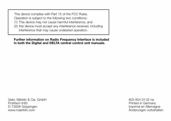
This device complies with Part 15 of the FCC Rules. Operation is subject to the following two conditions:(1) This device may not cause harmful interference, and(2) this device must accept any interference received, including
interference that may cause undesired operation.
Gebr. Märklin & Cie. GmbHPostfach 8 60D-73008 Göppingenwww.maerklin.com
603 824 01 02 naPrinted in GermanyImprimé en AllemagneÄnderungen vorbehalten
Further information on Radio Frequency Interface is includedin both the Digital and DELTA central control unit manuals.