Embed Size (px)
Citation preview

Kompakte Bauform ■Compact desig
Höchste Drehzahlen bis zu ■26.000 U/minHigh speeds up to 26,000 rpm
Hohe EMV-Festigkeit ■High EMC immunity
Keine magnetischen ■Komponenten oder Felder, Hysterese oder Entmagneti-sierungsgefahrNo magnetic components No magnetic field hystere-sis or demagnetisation risk
Schutzklasse IP67 ■wasserdichte ImpulsgeberProtection class IP67 Fluid submersible encoders
Spindelgeber nach dem AMOSIN® – MessprinzipSpindle encoder based on the AMOSIN® – Inductive Measuring Principle
AMO GmbH
AMOSIN® - Messprinzip
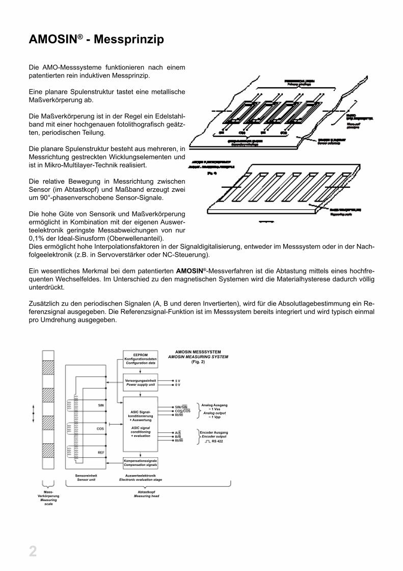
Die AMO-Messsysteme funktionieren nach einem patentierten rein induktiven Messprinzip.
Eine planare Spulenstruktur tastet eine metallische Maßverkörperung ab.
Die Maßverkörperung ist in der Regel ein Edelstahl-band mit einer hochgenauen fotolithografisch geätz-ten, periodischen Teilung.
Die planare Spulenstruktur besteht aus mehreren, in Messrichtung gestreckten Wicklungselementen und ist in Mikro-Multilayer-Technik realisiert.
Die relative Bewegung in Messrichtung zwischen Sensor (im Abtastkopf) und Maßband erzeugt zwei um 90°-phasenverschobene Sensor-Signale.
Die hohe Güte von Sensorik und Maßverkörperung ermöglicht in Kombination mit der eigenen Auswer-teelektronik geringste Messabweichungen von nur 0,1% der Ideal-Sinusform (Oberwellenanteil). Dies ermöglicht hohe Interpolationsfaktoren in der Signaldigitalisierung, entweder im Messsystem oder in der Nach-folgeelektronik (z.B. in Servoverstärker oder NC-Steuerung).
Ein wesentliches Merkmal bei dem patentierten AMOSIN®-Messverfahren ist die Abtastung mittels eines hochfre-quenten Wechselfeldes. Im Unterschied zu den magnetischen Systemen wird die Materialhysterese dadurch völlig unterdrückt.
Zusätzlich zu den periodischen Signalen (A, B und deren Invertierten), wird für die Absolutlagebestimmung ein Re-ferenzsignal ausgegeben. Die Referenzsignal-Funktion ist im Messsystem bereits integriert und wird typisch einmal pro Umdrehung ausgegeben.
Analog Ausgang ~ 1 Vss
Analog output~ 1 Vpp
Encoder Ausgang Encoder output
RS 422
EEPROM KonfigurationsdatenConfiguration data
VersorgungseinheitPower supply unit
ASIC Signal-konditionierung+ Auswertung
ASIC signalconditioning+ evaluation
KompensationssignaleCompensation signals
Mass-Verkörperung
Measuringscale
AuswerteelektronikElectronic evaluation stage
SensoreinheitSensor unit
AbtastkopfMeasuring head
AMOSIN MESSSYSTEMAMOSIN MEASURING SYSTEM
(Fig. 2)
2
AMOSIN® - Measuring principle
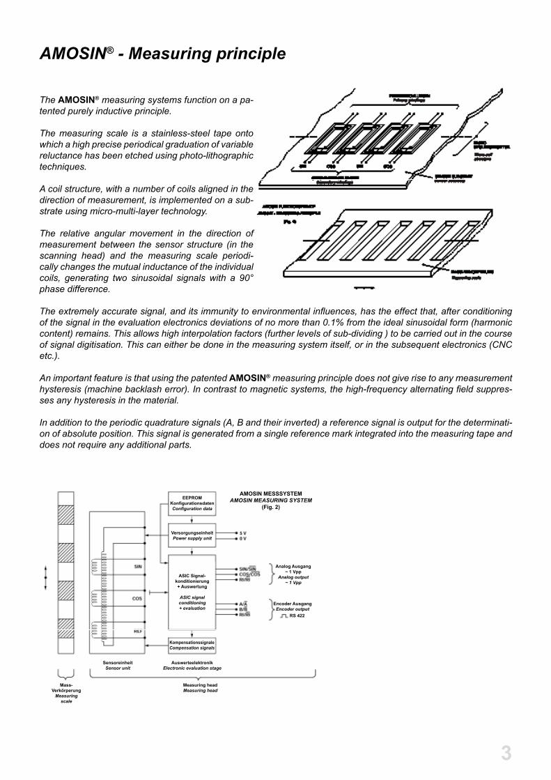
The AMOSIN® measuring systems function on a pa-tented purely inductive principle.
The measuring scale is a stainless-steel tape onto which a high precise periodical graduation of variable reluctance has been etched using photo-lithographic techniques.
A coil structure, with a number of coils aligned in the direction of measurement, is implemented on a sub-strate using micro-multi-layer technology.
The relative angular movement in the direction of measurement between the sensor structure (in the scanning head) and the measuring scale periodi-cally changes the mutual inductance of the individual coils, generating two sinusoidal signals with a 90° phase difference.
The extremely accurate signal, and its immunity to environmental influences, has the effect that, after conditioning of the signal in the evaluation electronics deviations of no more than 0.1% from the ideal sinusoidal form (harmonic content) remains. This allows high interpolation factors (further levels of sub-dividing ) to be carried out in the course of signal digitisation. This can either be done in the measuring system itself, or in the subsequent electronics (CNC etc.).
An important feature is that using the patented AMOSIN® measuring principle does not give rise to any measurement hysteresis (machine backlash error). In contrast to magnetic systems, the high-frequency alternating field suppres-ses any hysteresis in the material.
In addition to the periodic quadrature signals (A, B and their inverted) a reference signal is output for the determinati-on of absolute position. This signal is generated from a single reference mark integrated into the measuring tape and does not require any additional parts.
Analog Ausgang ~ 1 Vpp
Analog output~ 1 Vpp
Encoder Ausgang Encoder output
RS 422
EEPROM KonfigurationsdatenConfiguration data
VersorgungseinheitPower supply unit
ASIC Signal-konditionierung+ Auswertung
ASIC signalconditioning+ evaluation
KompensationssignaleCompensation signals
Mass-Verkörperung
Measuringscale
AuswerteelektronikElectronic evaluation stage
SensoreinheitSensor unit
Measuring headMeasuring head
AMOSIN MESSSYSTEMAMOSIN MEASURING SYSTEM
(Fig. 2)
3
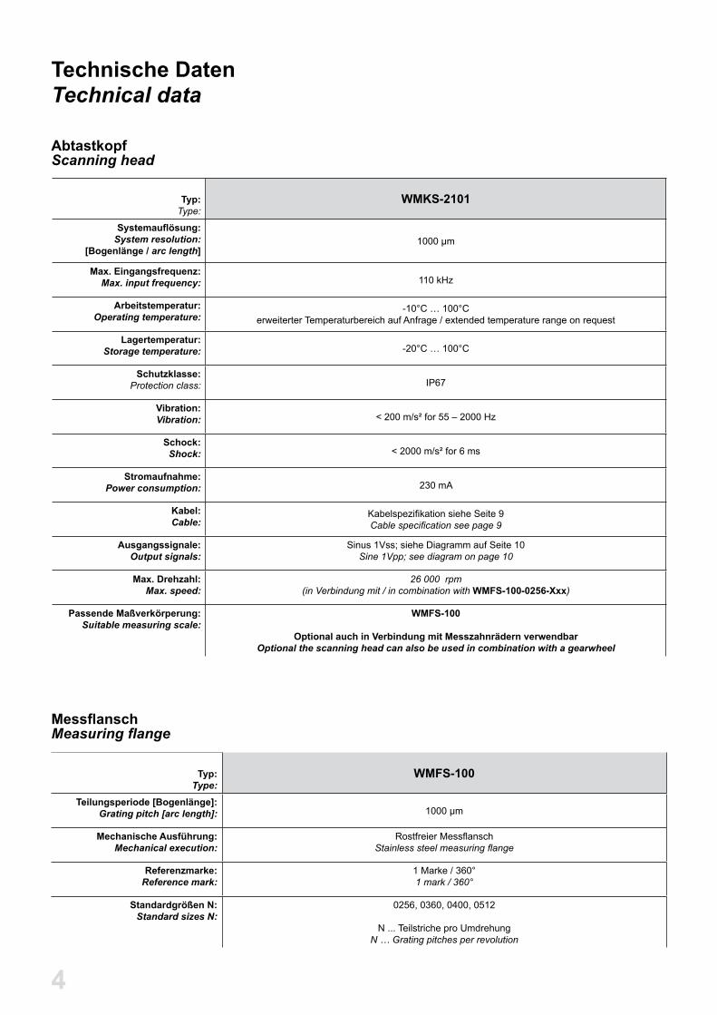
Technische DatenTechnical data
Typ:Type:
WMKS-2101
Systemauflösung:System resolution:
[Bogenlänge / arc length]1000 µm
Max. Eingangsfrequenz:Max. input frequency: 110 kHz
Arbeitstemperatur:Operating temperature:
-10°C … 100°C erweiterter Temperaturbereich auf Anfrage / extended temperature range on request
Lagertemperatur:Storage temperature: -20°C … 100°C
Schutzklasse:Protection class: IP67
Vibration:Vibration: < 200 m/s² for 55 – 2000 Hz
Schock:Shock: < 2000 m/s² for 6 ms
Stromaufnahme:Power consumption: 230 mA
Kabel:Cable:
Kabelspezifikation siehe Seite 9Cable specification see page 9
Ausgangssignale:Output signals:
Sinus 1Vss; siehe Diagramm auf Seite 10Sine 1Vpp; see diagram on page 10
Max. Drehzahl:Max. speed:
26 000 rpm (in Verbindung mit / in combination with WMFS-100-0256-Xxx)
Passende Maßverkörperung:Suitable measuring scale:
WMFS-100
Optional auch in Verbindung mit Messzahnrädern verwendbarOptional the scanning head can also be used in combination with a gearwheel
4
Typ:Type:
WMFS-100
Teilungsperiode [Bogenlänge]:Grating pitch [arc length]: 1000 µm
Mechanische Ausführung:Mechanical execution:
Rostfreier MessflanschStainless steel measuring flange
Referenzmarke:Reference mark:
1 Marke / 360°1 mark / 360°
Standardgrößen N:Standard sizes N:
0256, 0360, 0400, 0512
N ... Teilstriche pro UmdrehungN … Grating pitches per revolution
AbtastkopfScanning head
MessflanschMeasuring flange
5
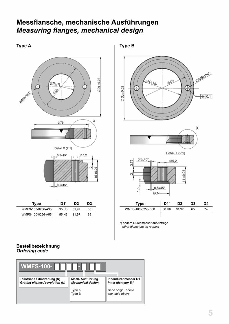
Messflansche, mechanische AusführungenMeasuring flanges, mechanical design
Type D1* D2 D3WMFS-100-0256-A35 35 H6 81,97 65
WMFS-100-0256-A55 55 H6 81,97 65
Type D1* D2 D3 D4WMFS-100-0256-B50 50 H6 81,97 65 74
Type A Type B
*) andere Durchmesser auf Anfrage other diameters on request
-WMFS-100-
Innendurchmesser D1Inner diameter D1
siehe obige Tabellesee table above
Mech. AusführungMechanical design
Type A Type B
Teilstriche / Umdrehung (N)Grating pitches / revolution (N)
BestellbezeichnungOrdering code
6
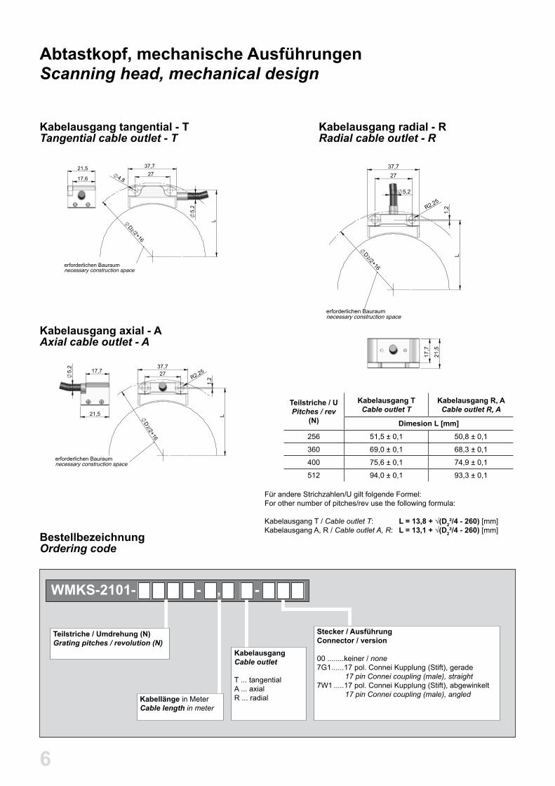
Abtastkopf, mechanische AusführungenScanning head, mechanical design
Kabelausgang axial - AAxial cable outlet - A
Kabelausgang tangential - TTangential cable outlet - T
Kabelausgang radial - RRadial cable outlet - R
BestellbezeichnungOrdering code
D /2+16
2737,7
4,8
5,2
L
17,6
21,5
erforderlichen Bauraumnecessary construction space
2
D /2+16
L
2737,7
5,2
R2,25
1,2
21,5
17,7
erforderlichen Bauraumnecessary construction space
2
D /2+16
2737,7
R2,25
1,2
L
17,7
21,5
5,2
erforderlichen Bauraumnecessary construction space
2
- , -WMKS-2101-
KabelausgangCable outlet
T ... tangentialA ... axialR ... radialKabellänge in Meter
Cable length in meter
Teilstriche / Umdrehung (N)Grating pitches / revolution (N)
Stecker / AusführungConnector / version
00 ........keiner / none7G1 ......17 pol. Connei Kupplung (Stift), gerade 17 pin Connei coupling (male), straight7W1 .....17 pol. Connei Kupplung (Stift), abgewinkelt 17 pin Connei coupling (male), angled
Teilstriche / UPitches / rev
(N)
Kabelausgang TCable outlet T
Kabelausgang R, ACable outlet R, A
Dimesion L [mm]
256 51,5 ± 0,1 50,8 ± 0,1
360 69,0 ± 0,1 68,3 ± 0,1
400 75,6 ± 0,1 74,9 ± 0,1
512 94,0 ± 0,1 93,3 ± 0,1
Für andere Strichzahlen/U gilt folgende Formel:For other number of pitches/rev use the following formula:
Kabelausgang T / Cable outlet T: L = 13,8 + √(D2²/4 - 260) [mm]Kabelausgang A, R / Cable outlet A, R: L = 13,1 + √(D2²/4 - 260) [mm]

MontagezeichnungAssembly drawing
2737,7
2x4,8
5,2
75
D
D H6
2xM6
D
Luftspalt 0,15±0,05Air gap 0,15 ±0,05
3
2
1
17,621,5
17
3,5 ±0,5
2
15
0,1 B
B
Zählrichtung +
Count direction +
27
37,7
R2,25
1,2
D 2xM6
D
D H61
Luftspalt 0,15±0,05Air gap 0,15 ±0,05
Zählrichtung +
Count direction +
17,721,5
5,2
11
4,5 ±0,5
0,1 B
B2
3
Messflansch WMFS-100-xxxx-AxxMeasuring flange WMFS-100-xxxx-Axx
Messflansch WMFS-100-xxxx-BxxMeasuring flange WMFS-100-xxxx-Bxx
7
Anbautoleranzen gelten für alle AbtastkopfausführungenMounting tolerances are valid for all scanning head designs
Anbautoleranzen gelten für alle AbtastkopfausführungenMounting tolerances are valid for all scanning head designs
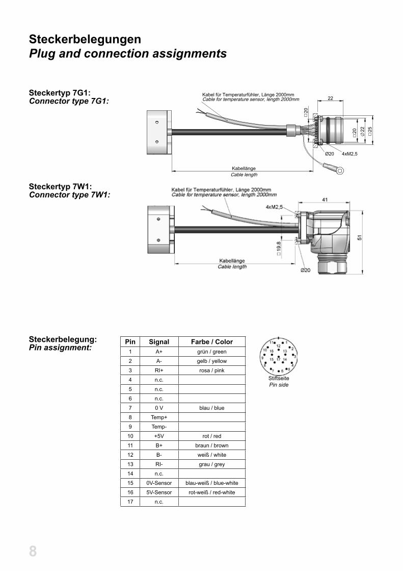
SteckerbelegungenPlug and connection assignments
8
Pin Signal Farbe / Color1 A+ grün / green
2 A- gelb / yellow
3 RI+ rosa / pink
4 n.c.
5 n.c.
6 n.c.
7 0 V blau / blue
8 Temp+
9 Temp-
10 +5V rot / red
11 B+ braun / brown
12 B- weiß / white
13 RI- grau / grey
14 n.c.
15 0V-Sensor blau-weiß / blue-white
16 5V-Sensor rot-weiß / red-white
17 n.c.
22 25
22
20
Kabellänge
20
Cable length
Kabel für Temperaturfühler, Länge 2000mmCable for temperature sensor, length 2000mm
4xM2,5Ø20
Steckertyp 7G1:Connector type 7G1:
Steckertyp 7W1:Connector type 7W1:
Steckerbelegung:Pin assignment:
StiftseitePin side
9
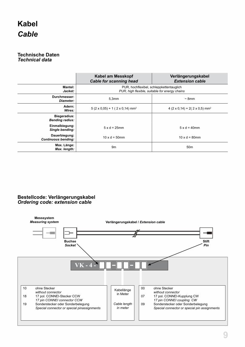
KabelCable
Technische DatenTechnical data
Kabel am MesskopfCable for scanning head
VerlängerungskabelExtension cable
Mantel:Jacket:
PUR, hochflexibel, schleppkettentauglichPUR, high flexible, suitable for energy chains
Durchmesser:Diameter: 5,3mm ~ 8mm
Adern:Wires: 5 (2 x 0,05) + 1 ( 2 x 0,14) mm2 4 (2 x 0,14) + 2( 2 x 0,5) mm2
Biegeradius:Bending radius:Einmalbiegung:Single bending: 5 x d = 25mm 5 x d = 40mm
Dauerbiegung:Continuous bending: 10 x d = 50mm 10 x d = 80mm
Max. Länge:Max. length: 9m 50m
Bestellcode: VerlängerungskabelOrdering code: extension cable
VK - 4 -
00 ohne Stecker without connector07 17 pol. CONNEI-Kupplung CW 17 pin CONNEI coupling CW09 Sonderstecker oder Sonderbelegung Special connector or special pin assignments
Kabellänge in Meter
Cable length in meter
10 ohne Stecker without connector18 17 pol. CONNEI-Stecker CCW 17 pin CONNEI connector CCW19 Sonderstecker oder Sonderbelegung Special connector or special pinassignments
MesssystemMeasuring system
BuchseSocket
StiftPin
Verlängerungskabel / Extension cable
10
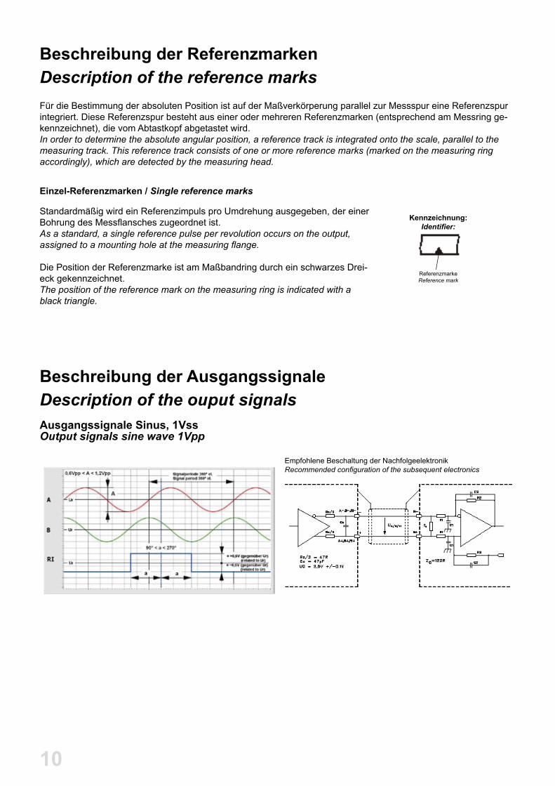
Beschreibung der ReferenzmarkenDescription of the reference marksFür die Bestimmung der absoluten Position ist auf der Maßverkörperung parallel zur Messspur eine Referenzspur integriert. Diese Referenzspur besteht aus einer oder mehreren Referenzmarken (entsprechend am Messring ge-kennzeichnet), die vom Abtastkopf abgetastet wird.In order to determine the absolute angular position, a reference track is integrated onto the scale, parallel to the measuring track. This reference track consists of one or more reference marks (marked on the measuring ring accordingly), which are detected by the measuring head.
Einzel-Referenzmarken / Single reference marks
Standardmäßig wird ein Referenzimpuls pro Umdrehung ausgegeben, der einer Bohrung des Messflansches zugeordnet ist.As a standard, a single reference pulse per revolution occurs on the output, assigned to a mounting hole at the measuring flange.
Die Position der Referenzmarke ist am Maßbandring durch ein schwarzes Drei-eck gekennzeichnet.The position of the reference mark on the measuring ring is indicated with a black triangle.
Kennzeichnung:Identifier:
ReferenzmarkeReference mark
Beschreibung der AusgangssignaleDescription of the ouput signalsAusgangssignale Sinus, 1VssOutput signals sine wave 1Vpp
Empfohlene Beschaltung der NachfolgeelektronikRecommended configuration of the subsequent electronics

NotizenNotices
11

A-4963 St. Peter am Hart, Nöfing 4 - Austria
Phone: +43 7722 658 56-0Fax: +43 7722 658 56-11
e-mail: [email protected]
www.amo-gmbh.com
© AMO GmbH / SN: WMIS-P 20140108Technische Änderungen vorbehalten.
Technical Data are subject to change without notice.
AMO GmbH
Inkrementelle LÄNGENMESSSYSTEME nach dem induktiven AMOSIN® – Messprinzip
Incremental LENGTH MEASURING SYSTEMS based on the AMOSIN® – Inductive Measuring Principle
AMO GmbH
Inkrementelle WINKELMESSSYSTEME nach dem induktiven AMOSIN® – Messprinzip
Incremental ANGLE MEASURING SYSTEMS based on the AMOSIN® – Inductive Measuring Principle
Additional information brochures:
Branches:
Germany:
AMO GmbHZweigniederlassung Deutschland
Bussardstrasse 10D 78655 Dunningen
Phone: +49 7403 913 283Fax.: +49 7403 913 267
e-mail: [email protected]
USA:
AMO Corporation9580 Oak Ave Parkway Suite 7-162
Folsom, CA 95630
Phone: +1 916 791 2001Fax: +1 916 720 0430
E-mail: [email protected]: www.amosin.com
Italy:
AMO Italia s.r.l.20037 Dugnano MI - Italia
Via Gorizia 35
Phone: +39 029 108 23 41
E-mail: [email protected]: www.amoitalia.it
Authorized distributors and sales partners in other countries:Please look at www.amo-gmbh.com
Headquarter:


![Untersuchungen zu Nanocellulose-Verstärkten ... · der Scherebene entsteht ein Potential, das elektrokinetisches Potential oder Zeta-Potential genannt wird.[22] 2.1.3 Messprinzip](https://img.pdfslide.org/doc/110x75/6062f27b65c128661e5301b1/untersuchungen-zu-nanocellulose-verstrkten-der-scherebene-entsteht-ein-potential.jpg)


![Jahresrückblick 2013.ppt [Kompatibilitätsmodus] · Hl.Abend • Besichtigung des Triebwerksprüfstandes in ZIPF • AMO-Treffen am GÜPl • 3 externe Stammtische in WIEN. 13er-Musikkorps](https://img.pdfslide.org/doc/110x75/612d21a91ecc51586941ffa6/jahresrckblick-2013ppt-kompatibilittsmodus-hlabend-a-besichtigung-des.jpg)