Embed Size (px)
Citation preview

1
Lama# 6991001
www.ikarus.net
Deutsch: Bedienungsanleitung
English: User Manual
Français: Manuel d’utilisation
6991001-0907
2
Einleitung............................................................... 3Technische Daten.................................................. 3Die Paddelstange.................................................. 4Das Höhenleitwerk................................................. 5Die Empfängerantenne.......................................... 5Vor dem Flug......................................................... 6Ladegerät und Akku............................................... 7Die Fernsteuerung................................................. 9Senderumbau........................................................ 10Die verschiedenen Modi........................................ 12Einstellmöglichkeiten am Heli................................ 13Die Motore............................................................. 14Flugsteuerung........................................................ 15Flugpraxis.............................................................. 16Problembehandlung............................................... 17Ersatzteile.............................................................. 18Sicherheitshinweise............................................... 19
Inhaltsverzeichnis
3
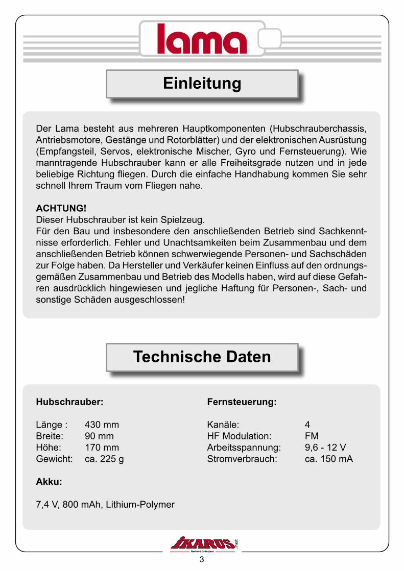
Einleitung
Der Lama besteht aus mehreren Hauptkomponenten (Hubschrauberchassis, Antriebsmotore, Gestänge und Rotorblätter) und der elektronischen Ausrüstung (Empfangsteil, Servos, elektronische Mischer, Gyro und Fernsteuerung). Wie manntragende Hubschrauber kann er alle Freiheitsgrade nutzen und in jede beliebige Richtung fliegen. Durch die einfache Handhabung kommen Sie sehr schnell Ihrem Traum vom Fliegen nahe.
ACHTUNG!Dieser Hubschrauber ist kein Spielzeug.Für den Bau und insbesondere den anschließenden Betrieb sind Sachkennt-nisse erforderlich. Fehler und Unachtsamkeiten beim Zusammenbau und dem anschließenden Betrieb können schwerwiegende Personen- und Sachschäden zur Folge haben. Da Hersteller und Verkäufer keinen Einfluss auf den ordnungs-gemäßen Zusammenbau und Betrieb des Modells haben, wird auf diese Gefah-ren ausdrücklich hingewiesen und jegliche Haftung für Personen-, Sach- und sonstige Schäden ausgeschlossen!
Hubschrauber: Fernsteuerung:
Länge : 430 mm Kanäle: 4Breite: 90 mm HF Modulation: FMHöhe: 170 mm Arbeitsspannung: 9,6 - 12 VGewicht: ca. 225 g Stromverbrauch: ca. 150 mA
Akku: 7,4 V, 800 mAh, Lithium-Polymer
Technische Daten

4
Montieren Sie zuerst die Pad-delstange und clipsen Sie das Gestänge an ei-ner der Kugeln am Rotorkopf ein.
Die Paddelstange
4.
Loch Ø 1,2 mm
1. 3.
2.
Kontrollieren Sie vor jedem Flug den korrekten Sitz der Paddelgewichte!
Montage der Paddelgewichte:
1. Schieben Sie die schwarze Kunststoffhülle über die Paddelstange.2. Drehen Sie die Hülle um 90°.3. Schieben Sie die Hülle zurück, sodass der Haken der Paddelstange in das 1,2 mm Loch in der Hülle greift.4. Schieben Sie das Paddelgewicht von innen in die Hülle.

5
Wickeln Sie die Antenne des Emp-fängers ab und führen Sie sie an einer geeigneten Stelle aus der Ka-binenhaube heraus. Lassen Sie die Antenne frei hängen, achten Sie allerdings darauf, dass sie nicht in bewegliche Teile wie Zahnräder, Rotoren etc. geraten kann. Fixieren Sie die Antenne an einem Kufenbü-gel mit einem Stück Klebeband.
Das Höhenleitwerk
Montieren Sie das beiligende Höhenleitwerk wie in den Abbildungen dargestellt.
Klebestreifen
Antenne
Die Empfängerantenne

6
Vor dem Start
Wichtig
Laden Sie die Flugakkus vor dem ersten Flug ca. 2 Stunden lang auf, bevor Sie fliegen. Benutzen Sie ausschließlich einen geeigneten Lader. Lithium Poly-mer Akkus dürfen nur mit Lithium Ladern geladen werden. Eine Nichtbeachtung kann zur Zerstörung oder in Brandsetzung des Akkus führen!
Bei nachlassender Akkuspannung den Hubschrauber unbedingt landen! Bitte den Akku jetzt entnehmen und nach dem Abkühlen erneut laden.
Der Lama ist ein betriebsbereiter Hubschrauber. Das Modell wurde genauen Kontrollen unterworfen, bevor es die Fabrik verließ. Aber Kontrollen und Justa-gen sind vor jedem Start notwendig, um einen unbeschwerten Flug genießen zu können.
Achten Sie darauf, dass die Rotorblattbefestigungsschrauben an den Hauptro-torblättern nicht zu fest angezogen sind. Sind die Rotorblätter zu stramm ange-zogen, können die Blätter sich nicht ausrichten, dies führt zu einem unsauber laufenden Rotorkopf. Beachten Sie, dass die Rotorblätter immer paarig verwen-det werden, keinesfalls dürfen diese untereinander gemischt werden.
Setzen Sie acht Mignon-Batterien (nicht im Set enthalten) in die Batteriehalte-rung des Senders ein. Achten Sie bitte darauf, dass der Schacht mit vier Batte-rien von der Vorderseite und mit vier Batterien von der Rückseite befüllt werden muss. Um die Rückseite zu befüllen, bitte die Batteriehalterung einmal komplett herausnehmen.
Sie sind gesetzlich verpflichtet, gebrauchte Batterien/ Akkus gesondert zu ent-sorgen. Bitte geben sie diese an einer kommunalen Sammelstelle oder im Han-del vor Ort ab.
7
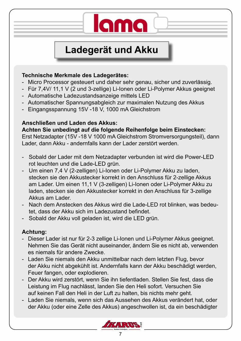
Technische Merkmale des Ladegerätes:- Micro Processor gesteuert und daher sehr genau, sicher und zuverlässig.- Für 7,4V/ 11,1 V (2 und 3-zellige) Li-Ionen oder Li-Polymer Akkus geeignet- Automatische Ladezustandsanzeige mittels LED- Automatischer Spannungsabgleich zur maximalen Nutzung des Akkus- Eingangsspannung 15V -18 V, 1000 mA Gleichstrom Anschließen und Laden des Akkus:Achten Sie unbedingt auf die folgende Reihenfolge beim Einstecken: Erst Netzadapter (15V -18 V 1000 mA Gleichstrom Stromversorgungsteil), dann Lader, dann Akku - andernfalls kann der Lader zerstört werden.
- Sobald der Lader mit dem Netzadapter verbunden ist wird die Power-LED rot leuchten und die Lade-LED grün.- Um einen 7,4 V (2-zelligen) Li-Ionen oder Li-Polymer Akku zu laden, stecken sie den Akkustecker korrekt in den Anschluss für 2-zellige Akkus am Lader. Um einen 11,1 V (3-zelligen) Li-Ionen oder Li-Polymer Akku zu laden, stecken sie den Akkustecker korrekt in den Anschluss für 3-zellige Akkus am Lader.- Nach dem Anstecken des Akkus wird die Lade-LED rot blinken, was bedeu- tet, dass der Akku sich im Ladezustand befindet. - Sobald der Akku voll geladen ist, wird die LED grün.
Achtung:- Dieser Lader ist nur für 2-3 zellige Li-Ionen und Li-Polymer Akkus geeignet. Nehmen Sie das Gerät nicht auseinander, ändern Sie es nicht ab, verwenden es niemals für andere Zwecke.- Laden Sie niemals den Akku unmittelbar nach dem letzten Flug, bevor der Akku nicht abgekühlt ist. Andernfalls kann der Akku beschädigt werden, Feuer fangen, oder explodieren.- Der Akku wird zerstört, wenn Sie ihn tiefentladen. Stellen Sie fest, dass die Leistung im Flug nachlässt, landen Sie den Heli sofort. Versuchen Sie auf keinen Fall den Heli in der Luft zu halten, bis nichts mehr geht. - Laden Sie niemals, wenn sich das Aussehen des Akkus verändert hat, oder der Akku (oder eine Zelle des Akkus) angeschwollen ist, da ein beschädigter
Ladegerät und Akku

8
Technische Daten:
Eingangsspannung: 15V – 18V Eingangsstrom: 1000 mA GleichstromAusgangsspannung: 2 Zellen 7,4V Buchse: 8,4V 3 Zellen 11,1V Buchse: 12,6VAusgangsstrom: 750 mA
Akku LaderStromversorungsteil
Polaritäts-zuordnung
12,6V 8,4V 4,2V 0V
Ladebuchse für 7,4 V Akkus
Eingangs-buchse
Power-LED
Lade/ Ladezu-stands-LED
Ladebuchse für 11,1 V Akkus
Anschlussschema
Akku sich kurzschliessen kann, Feuer fangen, oder explodieren kann.- Laden Sie niemals den Akku in der Nähe einer Hitzequelle oder unter direkter Sonneneinstrahlung.- Um einen Kurzschluss oder andere unvorhersehbare Unfälle zu vermeiden, benützen Sie den Lader niemals in feuchtem Zustand.- Vermeiden Sie, dass Flüssigkeiten oder Fremdkörper in den Lader geraten. In diesem Fall schalten Sie sofort die Stromversorgung aus, ziehen den Akku ab und senden Sie das Gerät an Ihren örtlichen Händler oder direkt an unsere Firma zur Reparatur.- Stellen Sie den Lader auf eine flache, nicht entflammbare Oberfläche. Lassen Sie ihn nicht fallen und vermeiden Sie es, das Gerät anzustossen.- Bevor Sie den Akku an den Lader anschliessen, stellen Sie sicher, dass die Polarität des Akkus und des Laders gleich sind, um Schaden an Ihrem Akku oder dem Lader zu vermeiden.- Verwenden Sie den Netzadapter nur in Verbindung mit dem Lader, versu- chen Sie niemals andere Geräte oder die Fernsteuerung damit zu laden. - Laden Sie jeweils nur einen Akku. Wenn sie zwei Akkus gleichzeitig laden werden der Lader und/oder der Akku beschädigt oder können Feuer fangen.
Lader

9
Stromversorgung:
Zum Betrieb des Senders sind 8 Trockenbatterien bzw. 8 NC-Zellen oder ein Akkupack mit 9,6Volt erforderlich.
Überprüfen Sie bitte den Hubschrauber durch die folgenden Schritte, um die Zuverlässigkeit des Fluges sicherzustellen.Die Antenne des Senders sollte voll ausgezogen sein und der Gasknüppel in Minimalposition sein. Die Trimmung der Gasfunktion sollte ebenfalls in Mini-malposition sein. Schalten Sie den Sender ein. Plazieren Sie den Hubschrauber
Die Fernsteuerung
Akkuspannung
Antenne
Ein/ Aus
Trimmung
Knüppel für Gas und Heck
Gurtbefestigung
Trimmung
Knüppel für Heck und Roll
Schalter (nicht belegt)
Übersicht
Simulatorbuchse
Schalter (nicht belegt)
Technische Daten:
System: 4-Kanal-SenderModulation: FM (PPM)Sendefrequenz: 35 / 40 MhzFunktionen: 4 (entspr. 4 Servos)Betriebsspannung: 9,6-12 Volt
10
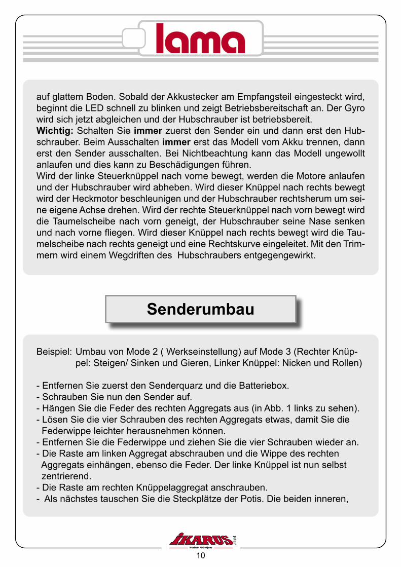
Beispiel: Umbau von Mode 2 ( Werkseinstellung) auf Mode 3 (Rechter Knüp- pel: Steigen/ Sinken und Gieren, Linker Knüppel: Nicken und Rollen)
- Entfernen Sie zuerst den Senderquarz und die Batteriebox.- Schrauben Sie nun den Sender auf.- Hängen Sie die Feder des rechten Aggregats aus (in Abb. 1 links zu sehen).- Lösen Sie die vier Schrauben des rechten Aggregats etwas, damit Sie die Federwippe leichter herausnehmen können.- Entfernen Sie die Federwippe und ziehen Sie die vier Schrauben wieder an.- Die Raste am linken Aggregat abschrauben und die Wippe des rechten Aggregats einhängen, ebenso die Feder. Der linke Knüppel ist nun selbst zentrierend.- Die Raste am rechten Knüppelaggregat anschrauben.- Als nächstes tauschen Sie die Steckplätze der Potis. Die beiden inneren,
Senderumbau
auf glattem Boden. Sobald der Akkustecker am Empfangsteil eingesteckt wird, beginnt die LED schnell zu blinken und zeigt Betriebsbereitschaft an. Der Gyro wird sich jetzt abgleichen und der Hubschrauber ist betriebsbereit.Wichtig: Schalten Sie immer zuerst den Sender ein und dann erst den Hub-schrauber. Beim Ausschalten immer erst das Modell vom Akku trennen, dann erst den Sender ausschalten. Bei Nichtbeachtung kann das Modell ungewollt anlaufen und dies kann zu Beschädigungen führen. Wird der linke Steuerknüppel nach vorne bewegt, werden die Motore anlaufen und der Hubschrauber wird abheben. Wird dieser Knüppel nach rechts bewegt wird der Heckmotor beschleunigen und der Hubschrauber rechtsherum um sei-ne eigene Achse drehen. Wird der rechte Steuerknüppel nach vorn bewegt wird die Taumelscheibe nach vorn geneigt, der Hubschrauber seine Nase senken und nach vorne fliegen. Wird dieser Knüppel nach rechts bewegt wird die Tau-melscheibe nach rechts geneigt und eine Rechtskurve eingeleitet. Mit den Trim-mern wird einem Wegdriften des Hubschraubers entgegengewirkt.

11
Raste an-schrauben
Federwippe ausbauen
Feder ent-fernen
Feder ein-hängen
Federwippe einbauen
Raste ab-schrauben
Abb. 1
Legen Sie die Reverse - Schalter (Dip – Schalter) 1 und 2 auf der Rückseite des Senders um, damit die Laufrich-tungen der Servos stimmen. Kontrol-lieren Sie unbedingt vor dem ersten Flug, ob die Laufrichtungen der Ser-vos wirklich korrekt sind.Die DIP-Schalter sind den Knüppelfunktionen wie abgebildet zugeordnet (Schalter 5 - 8 sind nicht belegt):
1 2 3 4 5 6 7 8
ON DIP
4
21
3
sowie die beiden äußeren Stecker werden miteinander vertauscht (siehe Skiz-zen im Kapitel „Die verschiedenen Modi“). Vorsicht beim Abziehen der Stecker, es darf sich kein Kabel lösen.- Sender wieder zusammenschrauben.
Abb. 2: Federwippe

12
Roll/ Querruder
Nic
k/ H
öhen
rude
r
Pitc
h/ G
as
Heck/ Seitenruder
Mode 2
+ +
++
1 2 3 4 5 6 7 8
ON DIP
Außer der Gasfunktion können auch die anderen Steuerfunktionen anders zu-geordnet werden. Die verschiedenen Kombinationen werden als Mode 1, Mode 2, Mode 3 und Mode 4 bezeichnet. Die nachfolgenden Abbildungen zeigen die vier verschiedenen Modi mit der entsprechenden Steckung der Potis, sowie die Position der DIP-Schalter.
Die verschiedenen Modi
Roll/ Querruder
Nic
k/ H
öhen
rude
r
Pitc
h/ G
as
Heck/ Seitenruder
Mode 1
+ +
++
1 2 3 4 5 6 7 8
ON DIP
Steckung der Potis im Sender (Schema-tische Darstellung des aufgeklappten Senders.
DIP-Schalter (auf der Unterseite des Senders)

13
1 2 3 4 5 6 7 8
ON DIP
1 2 3 4 5 6 7 8
ON DIP
Roll/ Querruder
Nic
k/ H
öhen
rude
r
Pitc
h/ G
as
Heck/ Seitenruder
Mode 4
+ +
++
Roll/ Querruder
Nic
k/ H
öhen
rude
r
Pitc
h/ G
as
Heck/ Seitenruder
Mode 3
Wenn Sie von Links auf den Heli schauen, sehen Sie an der Elektronik in der Kabine zwei Potis. Diese können mit dem beiligenden Schlitzschraubendreher verstellt werden. Der obere (SENSITIVE) ist für die Empfindlichkeit des Gyrosys-tems (Stabilisierung um die Hochachse) verantwortlich. Je weiter er im Uhrzei-
Einstellmöglichkeiten am Heli
+ +
++
14
gersinn gedreht wird, desto mehr greift der Kreisel ein. In der Regel muss hier nichts geändert werden. Mit dem unteren Poti (EXTEND) können Sie die Bewegungen der Servos ver-größern (Drehung im Uhrzeigersinn) oder verkleinern (Drehung gegen den Uhr-zeigersinn). Vergrößern Sie die Ausschläge, reagiert der Heli heftiger auf Ihre Steuerimpulse, werden die Ausschläge verkleinert, reagiert der Heli zahmer. Achtung: Bei großen Ausschlägen kann es passieren, dass die Stabistange des oberen Rotors bei heftigen Steuerbewegungen in den unteren Rotor schlägt.
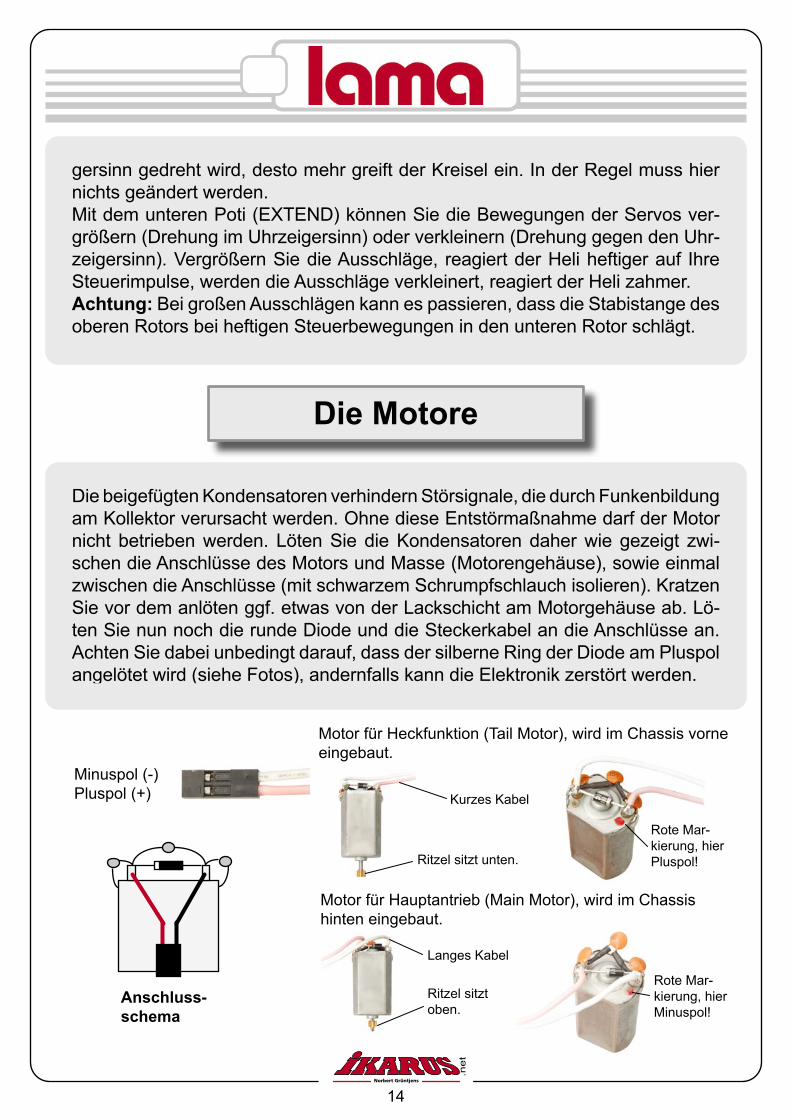
Minuspol (-)Pluspol (+)
Anschluss-schema
Motor für Hauptantrieb (Main Motor), wird im Chassis hinten eingebaut.
Ritzel sitzt oben.
Langes Kabel
Rote Mar-kierung, hier Minuspol!
Motor für Heckfunktion (Tail Motor), wird im Chassis vorne eingebaut.
Ritzel sitzt unten.
Kurzes Kabel
Rote Mar-kierung, hier Pluspol!
Die Motore
Die beigefügten Kondensatoren verhindern Störsignale, die durch Funkenbildung am Kollektor verursacht werden. Ohne diese Entstörmaßnahme darf der Motor nicht betrieben werden. Löten Sie die Kondensatoren daher wie gezeigt zwi-schen die Anschlüsse des Motors und Masse (Motorengehäuse), sowie einmal zwischen die Anschlüsse (mit schwarzem Schrumpfschlauch isolieren). Kratzen Sie vor dem anlöten ggf. etwas von der Lackschicht am Motorgehäuse ab. Lö-ten Sie nun noch die runde Diode und die Steckerkabel an die Anschlüsse an. Achten Sie dabei unbedingt darauf, dass der silberne Ring der Diode am Pluspol angelötet wird (siehe Fotos), andernfalls kann die Elektronik zerstört werden.

15
Linken Knüppel links
Drehunglinks
Rechten Knüppel rechts
Rechts
Rechten Knüppel links
Links
Rechten Knüppel zurück
Rückwärts abbremsen
Linken Knüppel vor
Steigen
Linken Knüppel zurück
Fallen
Rechten Knüppel vor
Vorwärts-flug
Linken Knüppel rechts
Drehung rechts
Flugsteuerung

16
Ein optimales Fluggelände ist ein windgeschützter Platz, ohne Hindernisse. Ein größerer leerer Raum ist ebenfalls sehr gut für die ersten Versuche geeignet.
Schalten Sie zunächst den Sender ein.Verbinden Sie den Stecker des Akkus mit der Buchse am Hubschrauber. Der Gasknüppel des Senders solte sich in der minimal Position befinden. Kontrol-lieren Sie die Taumelscheibe, diese sollte sich nahezu in waagerechter Position befinden.
Der Gyro gleicht sich ab, an der schnell blinkenden LED können Sie erkennen das der Hubschrauber einsatzbereit ist.
Achten Sie beim Start auf genügend großen Abstand vom Hubschrauber um das Verhalten des Hubschraubers gut erkennen zu können. Drücken Sie den Gasknüppel langsam nach vorne. Die Hauptrotoren werden beschleunigen. Je weiter der Gasknüppel nach vorn gedrückt wird um so leichter wird der Hub-schrauber, und er wird etwas nach links schieben. Falls der Hubschrauber noch in eine andere Richtung schiebt müssen Sie die Trimmer so lange verschieben bis dieses Verhalten nicht mehr oder nur gering auftritt.
Tasten Sie sich langsam an das Steuerverhalten des Hubschraubers heran.Versuchen Sie den Hubschrauber am Boden gezielt auf Punkte hin zu steuern. Achten Sie dabei auf geringe Flughöhe. Der Hubschrauber sollte anfangs nicht höher als einige Zentimeter fliegen.
Gelingt Ihnen diese Übung, so können Sie sich nun in größere Höhen vorarbeiten.
Flugpraxis

17
Wenn Sie den Hubschrauber jetzt über eine längere Zeit an einem Punkt halten können, sollten Sie versuchen den Heli mit gezielten Steuerbefehlen in eine Richtung zu steuern und wieder abzufangen.
Versuchen Sie den Hubschrauber auf einem vorgegebenen Punkt zu landen. Wenn diese Übungen sicher durchgeführt werden, können Sie die ersten Rund-flüge durchführen.
Gelingen alle Übungen sicher, können Sie sich als Hubschrauberpilot bezeich-nen.
Wir wünschen Ihnen viel Spaß mit dem Lama
Ihr Team von IKARUS - Norbert Grüntjens
Problembehandlung
Der Heli läuft nicht an: - Aus Sicherheitsgründen muss am Sender vor dem Einschalten des Helis
der Gashebel und dessen Trimmung in die unterste Stellung gebracht werden. Ist das nicht der Fall, läuft der Heli nicht an. Dazu müssen Sie ei-nen Moment warten, bis die grüne LED konstant leuchtet und nicht mehr blinkt. Davor dürfen Sie keine Steuerbewegungen durchführen.
- Der Akku ist leer und muss geladen werden.
Motoren laufen, Rotor dreht sich aber nicht:
- Sehen Sie nach, ob die Zahnräder ineinander greifen. Ist das nicht der Fall, lösen Sie die Schrauben des Motors und schieben den Motor weiter an das Hauptzahnrad heran.

18
Ersatzteile
Hau
ptro
torb
lätte
r#
6993
002
Pad
dels
tang
e#
6993
001
Hau
ptro
torw
elle
in
nen
# 69
9300
7
Li-P
o A
kku
800
mA
7,4
V#
6993
021
Bla
tthal
ter
# 69
9300
3
Get
riebe
set
# 69
9300
9
Pow
erbo
ard
# 69
9302
2
Taum
elsc
heib
e#
6993
004
Ges
täng
eset
# 69
9300
5
Hau
ptro
torw
elle
# 69
9300
8
Hau
ptm
otor
en#
6993
020
Hec
kaus
lege
r#
6993
012
Taum
elsc
heib
en-
halte
r#
6993
006
Taum
elsc
heib
en-
mitn
ehm
er#
6993
010
Akk
uhal
ter
# 69
9301
5
Land
eges
tell
# 69
9301
3
Ser
vo (1
Stü
ck)
# 69
9301
9
Li-P
o La
dege
rät
# 69
9302
3
ohne
Abb
ildun
g:
Cha
ssis
# 69
9301
1A
lum
iniu
mku
geln
#
6993
014
Sch
raub
ensa
tz
# 69
9301
6K
ugel
lage
rsat
z
# 69
9301
7
Wei
tere
Ers
atzt
eile
, Fer
nste
ueru
n-ge
n un
d Q
uarz
e fin
den
Sie
unt
er
ww
w.ik
arus
.net
.
Kab
inen
haub
e#
6993
018

19
1. Dieser Hubschrauber ist kein Spielzeug.Für den Bau und insbesondere den anschließenden Betrieb sind Sachkenntnis-seerforderlich. Fehler und Unachtsamkeiten beim Zusammenbau, Wartung und dem anschließenden Betrieb können schwerwiegende Personen- und Sachschä-den zur Folge haben.Da Hersteller und Verkäufer keinen Einfluss auf den ordnungsgemäßen Zusammen-bau, Wartung und Betrieb des Modells haben, wird auf diese Gefahren ausdrücklich hingewiesen.
2. Befolgen Sie genauestens die Montage- und Betriebsanleitung. Änderungen des Aufbaus und Nichteinhalten der Betriebsanleitung können zum Verlust jeglicher Ge-währleistung führen.
3. Auch vom vorschriftsmäßig aufgebauten Modell können Gefahren ausgehen. Greifen Sie niemals in drehende Rotorblätter und sonstige, offen liegende, sich be-wegende Teile, da ansonsten schwerwiegende Verletzungen entstehen können.
4. Grundsätzlich hat sich jeder Modellflieger so zu verhalten, dass die öffentliche Sicherheit und Ordnung, Personen und Sachen, sowie die Ordnung des Modellflug-betriebes nicht gefährdet oder gestört werden.Verwenden Sie nur Sie nur Akkus mit vorgeschriebener Zellenzahl und Kapazität. Bei zu hoher Zellenzahl kann der Elektromotor überlastet werden, durchbrennen, in Brand geraten und Funkstörungen verursachen.Die Rotorblätter bzw. die Schraubenaufhängungen können reißen und die Bruchstü-cke mit hoher Geschwindigkeit in alle Richtungen wegfliegen.
Bei zu geringer Zellenzahl ist ein störungsfreier Betrieb ebenfalls nicht möglich.Verwenden Sie immer voll geladene Akkus. Landen Sie das Modell rechtzeitig, be-vor entladene Akkus zu Fehlfunktion oder unkontrolliertem Absturz führen können. Prüfen Sie vor jedem Flug die RC- Anlage auf korrekte Funktion. Ruderausschläge müssen z.B. in die richtige Richtung gehen.Vergewissern Sie sich vor dem Einschalten des Modells, dass der eingestellte Kanal wirklich nur von Ihnen genutzt wird.Achten Sie auf freie Start- und Landeflächen. Beobachten Sie das Modell im Flug ständig.
Sicherheitshinweise
20
Table of Contents
Introduction............................................................ 21Technical Specification.......................................... 21The Flybar.............................................................. 22The Horizontal Sabilizers....................................... 23The Receiver Aerial............................................... 23Befor Your First Flight............................................ 24Charger and Battery............................................... 25The R/C Transmitter.............................................. 27Changing the Transmitter Mode............................ 28Die verschiedenen Modi........................................ 30Adjustments on the Helicopter............................... 31The Motors............................................................ 32Flight Maneuvers................................................... 33Practice.................................................................. 34Trouble Shooting................................................... 35Schematics - Replacement Parts.......................... 36Safety Instructions................................................. 37
21
Introduction
The Lama consists of several mechanical components (helicopter chassis, electric motors, pushrods, rotor blades) and the electronic equipment (receiver, servos, electronic mixer, gyro and transmitter). Just like a full size helicopter, the Lama can move around all axes and fly in any direction. The special design allows you to enjoy the first successful flights soon.
Attention! Read the entire manual before attempting your first flight!This model helicopter is not a toy. Building and especially operating it requires special knowledge. Mistakes and sloppiness during assembly, maintenance and operation may cause damage to property and/or persons. Even as this helicopter comes preassembled, it is your responsibility to check before every flight that all components are assembled properly and are undamaged. Make yourself aware of any possible dangers as you are responsible for the correct maintenance and operation of this model helicopter.
Helicopter: Remote Control:
Length : 430 mm (16.9 in) Channels: 4Fuselage Width: 90 mm (3.5 in) RF Modulation: FMHeigth: 170 mm (6.7 in) Operation Voltage: 9,6 - 12 VWeigth: 225 g (8 oz) Current Consumption: approx. 150 mA
Battery:
7,4 V, 800 mAh, Lithium-Polymer
Technical Specifications
1

22
First press the flybar seesaw into the center hub until it clicks into the the notches a n d then press the push-rod eyelet over one of the balls on the rotor head (Pict. 1 and 2).
The Flybar
Pict. 1 Pict. 2
4.
Hole 1.2 mm dia.
1. 3.
2.
Before every flight, please check the proper seating of the flybar weights.
Assembly of the paddle weights:1. Slide the black plastic sleeve onto the flybar. 2. Turn the sleeve by 90º.3. Slide the sleeve back for the hook to engage into the 1.2 mm hole in the sleeve.4. Slide the paddle weight into the inner opening of the sleeve.
Pict. 3

23
Unwind and straighten the receiver aerial and run it out of the canopy at a suitable location. Leave it han-ging free, but make sure it cannot get cought by moving parts like too-thed wheels, rotors, etc. Secure the antenna aerial with some self adhe-sive tape on one of the landing gear struts.
The horizontal stabilizers
Before your first flight, please mount the horizontal stabilizers as shown in the picture.
Tape
Antenna
The receiver aerial
24
The Lama is a preassembled model helicopter. The product has been inspected thoroughly before leaving the factory. But checks and adjustments are necessary before every operation, to enjoy unspoiled flight.
Check that the mounting screws for the main rotor blades are not too tight, as they blades may not be able to swing into opposite position to each other, which would result in dangerous vibrations. When replacing main blades, do this always in a pair and do not mix blades from different blade sets.Take the transmitter battery holder out of its compartment in the back of the transmit-ter. Insert the required (not included) 8 AA batteries. Be aware that the holder takes 4 batteries in the front and 4 in the back. You are legally responsible to properly dis-carding used batteries. Please contact your local authorities.
Place the included Lithium-Polymer flight battery on a non-flammable surface and charge it with the included special charger for about 2 hours before your first flight. Do not overcharge the battery. Future charge times may be shorter due to the fact that the battery may still hold a partial charge. If it is getting more than hand warm, disconnect the battery from the charger. Never charge the battery unattended. Never use a charger, which is not explicitly designed to charge this type of Li-Po batteries! Otherwise you may destroy the battery or it may even explode or cause fire.Land the helicopter as soon as you experience a power loss (helicopter gets sluggish). Take the battery out of the battery holder in the helicopter and let it cool down on a non-flammable surface before recharging. It is always a good idea, to have a second battery available to continue flying, while the first battery is getting recharged.
Before Your First Flight

25
Features of the Charger:- For more accuracy, safety and reliability a micro processor in the Charger monitors the entire charging process.- This Charger charges 2 (7.4V) and 3 (11.1 V) cell Lithium-Ion and Lithium-Polymer batteries.- The charging status is displayed via LEDs- Auto-detection of voltage differences between cells ensures maximum capacity and life span of your batteries.- Input jack: DC 15-18 V, 1000 mA
Attention: Important Safety Rules: - We recommend an old metal ammunition container for storage and charging of Li-Ion and Li-Po batteries. - Never leave batteries in your model. Store them properly.- Use this charger for 2 and 3-cell Li-Ion and Li-Po batteries only.- Never disassemble, alter or use the charger for other than the design purpose.- Never charge a battery immediately after the flight. Let it cool down first. Otherwise the battery will be damaged or destroyed. It may catch fire or even explode!- Never charge a battery which has changed its shape or has a “puffed up” cell. This indicates a damaged battery and it may short circuit itself, catch fire or even explode.- Never charge near a heat source or electronic equipment.- Never charge in direct sun shine or inside a car.- Never leave the battery unattended during charge process.- Never let the charger get wet nor use it under moist conditions to avoid short circuitry and other hazard as described before.- Never pour liquids onto the charger or let foreign objects get into the charger. In such a case, immediately cut off the power source, dis- connect the battery and return the charger to your local hobby shop or send it direct to us for service.- Always place the charger and battery on a flat, non-flammable surface.
Charger and Battery

26
- Never drop the charger nor hit it.- Never puncture a Li-Ion or Li-Poly battery.- Always check for correct polarity when connecting the battery. Other- wise the battery will be damaged or destroyed. It may catch fire or even explode!- Never charge more than one battery at a time. Otherwise the batteries will be damaged or destroyed. They may catch fire or even explode!- Always discard batteries according to the local regulation. Do not discard batteries with your household garbage.- If you deep discharge the battery it will be destroyed. As soon as you realize a power loss during flight, immediately land the helicopter and disconnect the battery. Never try to keep the helicopter flying until the motors stop running!
Monitoring the charge process:- First plug the Power Adapter to the wall outlet. Now connect the charger via its power jack to the 15V ... 18V power source. The Power LED will light up red, the Charge LED green.- When charging a 2-cell (7.4V) Li-Ion or Li-Po battery, plug the special battery connector into the charge jack for 2-cell (7.4V) batteries. The Charge LED will flash red indicating that the battery charger is in charge mode. As soon as the battery is fully charged the LED will turn green.- When charging a 3-cell (11.1V) Li-Ion or Li-Po battery, plug the special battery connector into the charge jack for 3-cell (11.1V) batteries. The Charge LED will flash red indicating that the battery charger is in charge mode. As soon as the battery is fully charged the LED will turn green.Pay attention to the connecting sequence – first wall plug, than charger, than battery – otherwise you will destroy the charger.
ATTENTION: Use the wall plug unit only in conjunction with the charger. Never attempt to charge any other components or R/C radios with it.
Output current: 750 mAInput current: 15V – 18V 1000 mA DCOutput voltage: 2 cells 7.4V charge jack : 8,4V 3 cells 11.1V charge jack: 12,6V
Technical Specification:

27
SchematicsCharger
Battery ChargerPower Adapter/ Power Source
Polarity Assign-ment Diagram
12.6V 8.4V 4.2V 0V
Charge jack for 2-cell (7.4V) batteries
Input Jack
Power LED
Charge/ Charge Status LED
Charge jack for 3-cell (11.1V) batteries
The R/C Transmitter
Antenna
Throttle/Tail Control Stick
Trim Lever
Forward/Roll Control Stick
Switch (not activated)Switch (not activated)
Voltage indicator
On-Off
Neck Strap Attachment
Simulator Socket
Trim Lever
Overview
Specifications:
System: 4 channel transmitterModulation: FM (PPM)Operating frequency: 72 MhzFunctions: 4 servosOperating power: 9.6 – 12 Volt

28
For example: change from Mode 2 (standard) to Mode 3 (right stick eleva- tor and rudder, left stick forward/backward pitch and roll)
- First remove the transmitter crystal and the battery box. - Unscrew the back of the transmitter. - Look at Pict. 1 and unhook the spring on the left gimbal stick unit. - For easier removal of the neutralizing lever (Pict. 2) loosen the four screws of the left gimbal stick unit a little. - Remove the neutralizing lever and tighten the four screws again. - Remove ratched from right unit (viewed as shown in above Pict. 1). Install the neutralizing lever (shown in Pict. 5) as well as the spring on the right unit. This gimbal stick is now self neutralizing. - Install the ratchet on the left unit at the location shown in Picture 1.
Changing the Transmitter Mode
Follow the checking procedure below to assure a safe flight:Place the helicopter on a flat and dust free surface. Fully extend the transmit-ter antenna. The throttle stick should be in idle position (left stick towards you). Switch on the transmitter. As soon as you connect the flight battery connector with the receiver the LED will flash fast, indicating that the system is ready. The incorporated gyro will calibrate itself and the helicopter is ready for opera-tion.
Important: Always switch on the transmitter first and than connect the flight battery in the helicopter. After the flight, disconnect first the flight battery and than switch off the transmitter. If you do not follow this sequence, the model may start up inadvertently and may get damaged and/or cause damage.When moving the left control stick on the transmitter forward both motors will start and the helicopter will lift off. If you move this stick to the right, the helicop-ter will turn to the right around the vertical axis. Move the right stick forward, the swash plate will tilt forward, the helicopter will lower its front (if in flight) and will fly forward. Moving the right stick to the right, the swash plate will tilt to the right and the helicopter will start a right turn.The trim sliders will assist you in preventing the drifting of the helicopter.

29
Install ratchet
Remove neutralizing lever
Remove spring
Install spring
Install neutralizing lever
Remove ratchet
Pict. 2: Neutralizing lever
Pict. 1
- Next swap the leads of the two gimbal stick units. Left inner lead onto right inner connector, left outer lead onto right outer connetor and visa versa. (siehe Kapitel „Die verschiedenen Modi“) - Be careful when pulling the connector off the circuit board in the transmitter rear cover so that no leads get pulled out of the connectors. Always pull on the connector housing, NOT on the leads.- Screw transmitter rear cover back on. - Change the setting of the reverse switches (DIP Switches) 1 and 2 on the back of the transmitter (Pict. 3) to correct the directional operation of the servos. Definitely check before your first flight, that the servo direction is actually correct.
Servo reverser switch:
You can reverse the servo operation direction with the help of the switches on the back of the transmitter. This has the advantage that you do not have to pay attention to the servo direction during installation into the model. The servo reverse switches are assigned as following (switches 5 – 8 are inherent):
1 2 3 4 5 6 7 8
ON DIP
4
21
3
Pict. 3

30
Roll/Aileron
Forw
ard
Pitc
h/E
leva
tor
Pitc
h/Th
rottl
e
Tail Rotor/Rudder
Mode 2
+ +
++
1 2 3 4 5 6 7 8
ON DIP
Die verschiedenen Modi
+ +
++
Roll/Aileron
Forw
ard
Pitc
h/E
leva
tor
Pitc
h/Th
rottl
e
Tail Rotor/Rudder
Mode 1
1 2 3 4 5 6 7 8
ON DIP
Potentiometer connections in the transmitter (Schematical presentation of the opened radio)
DIP-switches (at the transmitter rear case)
Außer der Gasfunktion können auch die anderen Steuerfunktionen anders zu-geordnet werden. Die verschiedenen Kombinationen werden als Mode 1, Mode 2, Mode 3 und Mode 4 bezeichnet. Die nachfolgenden Abbildungen zeigen die vier verschiedenen Modi mit der entsprechenden Steckung der Potis, sowie die Position der DIP-Schalter.

31
When looking at the left side of the helicopter (canopy pointing to the left), you will see two recessed potentiometers in the electronic box in the canopy. You may adjust them if necessary with the included flat-nose screw driver. The up-per one (Sensitive) is adjusting the sensitivity of the gyro system via the vertical axis. The further it is adjusted in clockwise direction, the more active the gyro will be. Normally nothing needs to be changed on the factory setting of this po-tentiometer.
Adjustments on the helicopter
1 2 3 4 5 6 7 8
ON DIP
Roll/Aileron
Forw
ard
Pitc
h/E
leva
tor
Pitc
h/Th
rottl
e
Tail Rotor/Rudder
Mode 4
+ +
++
1 2 3 4 5 6 7 8
ON DIP
+ +
++
Roll/Aileron
Forw
ard
Pitc
h/E
leva
tor
Pitc
h/Th
rottl
e
Tail Rotor/Rudder
Mode 3
32
With the lower potentiometer (Extend) the servo throw can be increased (clock-wise motion) or reduced (counter clockwise). If you increase the throw, the heli-copter will react stronger to the control inputs. Reducing the throw the helicopter will become more tame. Attention: Large aggressive control movements may make the flybar hit the main rotor below and may destroy them and/or the helicopter.
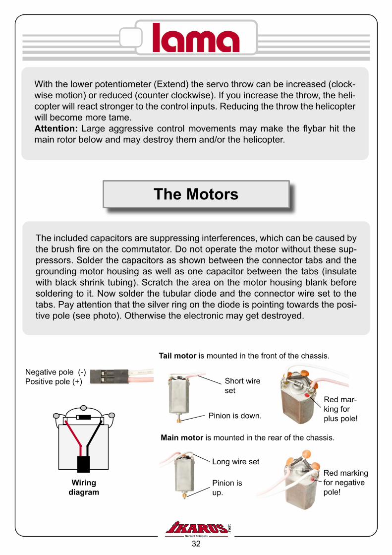
The included capacitors are suppressing interferences, which can be caused by the brush fire on the commutator. Do not operate the motor without these sup-pressors. Solder the capacitors as shown between the connector tabs and the grounding motor housing as well as one capacitor between the tabs (insulate with black shrink tubing). Scratch the area on the motor housing blank before soldering to it. Now solder the tubular diode and the connector wire set to the tabs. Pay attention that the silver ring on the diode is pointing towards the posi-tive pole (see photo). Otherwise the electronic may get destroyed.
The Motors
Main motor is mounted in the rear of the chassis.
Tail motor is mounted in the front of the chassis.
Pinion is up.
Pinion is down.
Long wire set
Short wire set
Negative pole (-)Positive pole (+)
Wiring diagram
Red marking for negative pole!
Red mar-king for plus pole!

33
Left stickto the left
Left Rotation
Right stickright
Right banking
Right stickleft
Left banking
Right stickbackwards
Flyingbackwardsstopping
Left stickforwards
Ascending
Left stickback-wards
Descen-ding
Right stick forward
Flying forward
Left stick to the right
Right Rotation
Flight Maneuvers

34
The best flying field is a wind protected area without any obstacles. A larger, empty room (double garage) is also suitable for the first attempts.
Switch on the transmitter. The throttle stick has to be idle position.Connect the flying battery to the receiver. Check that the swash plate is in hori-zontal position.The gyro will calibrate itself. As soon as the LED flashes fast, the helicopter is ready for operation.
Keep sufficient distance to the helicopter to be able to monitor its movements. Slowly push the throttle stick forward to accelerate the main rotors. The further forward you push the lighter the helicopter will become on the skids. It will slide slightly to the left. Should it slide into a different direction, use the trim levers of the corresponding control stick to compensate, until you corrected this move-ment.
Slowly familiarize yourself with the controls of the helicopter.Try to move the helicopter purposefully to predetermined stop points on the ground in front of you. Use duct tape as markers on the ground. Fly not more than about 2-3 inch off the ground during these maneuvers.
If you really master this exercise, you may fly higher now.
Now you will have to learn to hover, i.e. fly stationary above a predetermined point in front of you. If you really master this maneuver for at least 20 seconds,You should try to slowly move the helicopter into a predetermined direction and
Practice

35
than stop by going into a hover position above that point.
Now descend out of the hover position and land the helicopter. After mastering this maneuver you may proceed by attempting your first circular flight. Under-stand that your directional control is reversed when the helicopter is flying to-wards you.
If you have successfully accomplished this maneuver, you earned your first wings. You are now an R/C Helicopter pilot. Congratulations!
We are wishing you endless hours of fun with the Lama helicopter.
Your IKARUS-USA Team
Norbert Gruentjens
Trouble shooting
The helicopter does not start- For safety reasons you have to set the transmitter throttle stick and its trim lever into idle position (pull the stick and lever towards you) prior to switching on the transmitter. If this is not done, the helicopter will not start up. Now you need to wait a few moments until the green LED on the electronic unit does not flash anymore but lights up steady. In the meantime do not give any cont-rol inputs on the transmitter.- Your flight battery is discharged and requires to charging.
Motors are running, but the rotor is not spinning- Check that the gears are meshing. If not, loosen the screws of the motor and push the motor towards the larger gear. Run a strip of paper between motor pinion and gear to adjust for correct gear mesh. A too tight gear mesh will overload the motor and speed controller; a too loose gear mesh will destroy the main gear.

36
Schematics - Replacement parts
Set
of M
ain
Rot
or
Bla
des
# 69
9300
2
Flyb
ar#
6993
001
Inne
r Mai
nsha
ft#
6993
007
Li-P
o B
atte
ry
800
mA
7.4
V#
6993
021
Bla
de H
olde
r#
6993
003
Gea
r Set
# 69
9300
9
Pow
erbo
ard
# 69
9302
2
Sw
ash
Pla
te#
6993
004
Pus
hrod
Set
# 69
9300
5
Out
er M
ain
Sha
ft#
6993
008
Mot
or#
6993
020
Tail
Fram
e#
6993
012
Sw
ash
Pla
te
Hol
der
# 69
9300
6
Sw
ash
Pla
te
Follo
wer
# 69
9301
0
Bat
tery
Hol
der
# 69
9301
5
Land
ing
Gea
r#
6993
013
Ser
vo (1
pcs
.)#
6993
019
Li-P
o C
harg
er#
6993
023
Cha
ssis
# 69
9301
1A
lum
inum
Bal
ls
# 69
9301
4S
crew
Set
# 69
9301
6B
all B
earin
g S
et
# 69
9301
7
Tran
smitt
ers
and
Cry
stal
s:se
e w
ww
.ikar
us.n
et.
Can
opy
# 69
9301
8

37
1. This model helicopter is not a toy.Building and especially operating it requires special knowledge. Mistakes and sloppi-ness during assembly, maintenance and during operation may cause damage to pro-perty and/or persons. Even as this helicopter comes preassembled, it is your responsibility to check before every flight that all components are assembled properly and are undamaged. Make yourself aware of any possible dangers as you are responsible for the correct operation of this model helicopter.2. Meticulously follow the assembly and operation instructions. Alterations on the heli-copter or disregard of the instructions will void any warranty.3. Even a correctly assembled model may be dangerous. Never touch the moving main rotor blades or any other open parts during operation, as you may hurt yourself.4. In general it is your responsibility to use common sense, not to jeopardize safety and to prevent damage to property and persons.5. Only use original replacement parts and batteries of the same number of cells and capacity. Higher number of battery cells will overload and destroy the motors, cause a fire hazard and generate interference to the radio system.6. Smaller than 2 cell batteries will result in dangerous flight situations or no flight at all. Always check the battery after each charge, that all cells are o.k. If a cell is “puffed up”, properly discard the battery, as the battery is damaged beyond repair.7. Always use fully charged batteries. As soon as you feel a power loss in flight, land immediately, as low batteries can be responsible for malfunction and even a crash.8. Before every flight inspect the main rotor blades, blade holders and blade screws. If these items are damaged, they may fly away in any direction at high velocity and may cause damage to property and hurt people.9. Before every flight perform a range check. Have a second person observe the heli-copter while you walk away with the transmitter (antenna collapsed!) for about 25 yards. The control servos and motors in the helicopter need to perform flawless when carefully giving control input on the transmitter sticks. The servos have to move into the correct direction.10. Before switching on the transmitter, make sure, that nobody nearby (at least 1 mile radius) is using the same channel to operate a model.11. Make sure that your take-off and landing area is free of obstacles and persons. Al-ways keep a watchful eye on your model during flight.12. After landing immediately disconnect the flight battery and switch off your transmit-ter.
Safety Instructions
38
Sommaire
Introduction............................................................ 39Caractéristiques techniques.................................. 39Barre de Bell.......................................................... 40Das Höhenleitwerk................................................. 41Die Empfängerantenne.......................................... 41Les premiers pas................................................... 42Chargeur et Accu................................................... 43La radiocommande................................................ 45Changement de Mode........................................... 46Die verschiedenen Modi........................................ 48Possibilités de réglages sur l‘hélicoptère............... 49Die Motore............................................................. 50Commande de vol................................................. 51Practique de vol..................................................... 52Dépannage............................................................ 53Piéces de rechange............................................... 54Consignes de sécurité........................................... 55

39
Le Lama est constitué de plusieurs éléments principaux ( châssis, moteurs, tringles de commande et pales) et d’un équipement électronique (récepteur, servos, mixa-ge électronique, gyroscope et radiocommande).Tout comme l’original, ce modèle réduit peut évoluer dans toutes les directions. La simplicité de mise en œuvre et de pilotage vous permettrons d’obtenir rapidement des résultats probants.
Attention !Cet hélicoptère n’est pas un jouet.Pour le montage et par la suite en vol, un minimum de connaissances sont requi-ses. Des erreurs au cours du montage peuvent avoir de graves conséquences. Etant donné que ni le fabricant, ni le distributeur ne peuvent avoir une influence sur le montage et l‘utilisation correcte du modèle, nous ne pouvons qu‘attirer votre atten-tion sur ces risques, et déclinons toute responsabilité en cas d‘ accident.
Caractéristiques techniques
Hélicoptère : Radiocommande :
Longueur : 430 mm Nb de voies : 4Largeur 90 mm Module HF : FMHauteur : 170 mm Tension : 9,6 – 12 VPoids : env. 225 grs Consommation : env. 150 mA
Accu 8,4V 800 mAh LiPo
Introduction

40
Barre de Bell
Vue. 1 Vue. 2
Montez d’abord la barre de Bell et clip-sez la chape sur l’une des deux rotu-les du rotor supéri-eur (vue 1 et vue 2).
4.
Trou Ø 1,2 mm
1. 3.
2.
Avant chaque vol, vérifiez la fixation des poids de la barre de Bell.
Vue. 3
Montage des poids
1. Monter les douilles noires en plastiques sur la barre 2. Tourner la douille de 90° 3. Faire revenir la douille en arrière pour que le crochet de la barre se mette dans le trou de diamètre 1,2 mm 4. Faire glisser le poids dans la douille plastique

41
Déroulez l‘antenne du récepteur et faites la ressortir par la verrière. Laissez la prendre à l‘extérieur, en veillant à ce qu‘elle ne puisse pas se prendre dans des pièces en mouvement, pignons, rotor, etc. Fixez l‘antenne avec un bout de ruban adhésif sur le patin de l‘hélicoptère.
Das Höhenleitwerk
Avant le premier vol, montez les deux stabilisateurs selon la vue ci-dessous.
Klebestreifen
Antenne
Die Empfängerantenne

42
Le Lama est un hélicoptère prêt à voler. Ce modèle a été soigneusement con-trôlé avant livraison. Néanmoins pour un vol sans encombres, il vaut mieux vérifier et contrôler les différentes fonctions avant chaque décollage.
Veillez à ne pas trop serrer les vis de fixation des pales de rotor. Si elles sont trop serrées, elles ne pourront pas s’aligner lors de la rotation et pourront provo-quer des vibrations au niveau de la tête de rotor. Utilisez toujours les pales par paire, ; ne jamais remplacer une pale seule.
Montez les accus dans leur logement. N’oubliez pas qu’il faut monter 4 accus dans le logement par l’avant et 4 dans le logement situé à l’arrière. Pour les mettre dans le logement situé à l’arrière, il faut retirer le support d’accus. Vous ne pouvez jeter des accus ou batteries usagés aux ordures. Ramenez-les dans un centre de collecte près de chez vous.
Important
- Avant le vol, chargez les accus durant 2 heures environ. Utilisez un chargeur approprié. Les accus Lithium Polymère. Le non respect des consignes de char-ge peut provoquer l’explosion de l’accu, avec risque d’incendie.
- Dès que vous constatez une baisse de tension de l’accu, rechargez-le impé-rativement ! Retirez alors l’accu, et attendez qu’il soit refroidi avant de le rechar-ger.
Les premiers pas

43
Particularités techniques:
- commandé par microprocesseur, précis et fiable- pour accus Li-Ion ou Li-Polymère 7,4 V / 11,1 V (2 et 3 éléments)- Affichage automatique de l’état de charge par Led- Equilibrage automatique de la tension pour une utilisation optimale de l’accu- Entrée 15 V – 18 V, 1000 mA courant continu
Attention:
- ce chargeur n’est destiné qu’aux accus Li-Ion et Li-Polymère de 2-3 éléments. Ne démontez pas le chargeur, ne le modifiez pas et ne l’utilisez pas pour autre chose.- Ne chargez jamais l’accu immédiatement après le vol. Laissez-le refroidir. L’accu pourrait se détériorer, prendre feu ou exploser.- Ne mettez jamais en charge si vous remarquez une modification extérieure de l’accu (un élément « gonflé »), un accu endommagé peut se mettre en court-circuit, prendre feu ou exploser.- Ne jamais charger l’accu à proximité d’une source de chaleur ou en plein soleil.- Pour éviter tout court circuit au autres désagréments imprévisibles, ne jamais charger dans un endroit humide- Protéger le chargeur contre l’intrusion de produits liquides ou de corps étrangers. Dans ce cas, coupez immédiatement l’alimentation, débran- chez l’accu et envoyez le chargeur en SAV.- Posez le chargeur LiPo Balance sur une surface plane, non inflamm- able. Ne le faites pas tomber, et évitez les chocs.- Avant de brancher l’accu au chargeur, vérifiez la polarité de l’accu et du chargeur, pour éviter d’endommager l’accu et / ou le chargeur- Vous détériorez l’accu en le déchargeant trop fortement. Si vous con- statez une baisse de régime en vol, arrêtez immédiatement le vol et coupez l’accu. N’essayez en aucun cas d’aller jusqu’au «bout de l’accu» en vol.
Chargeur et Accu
44
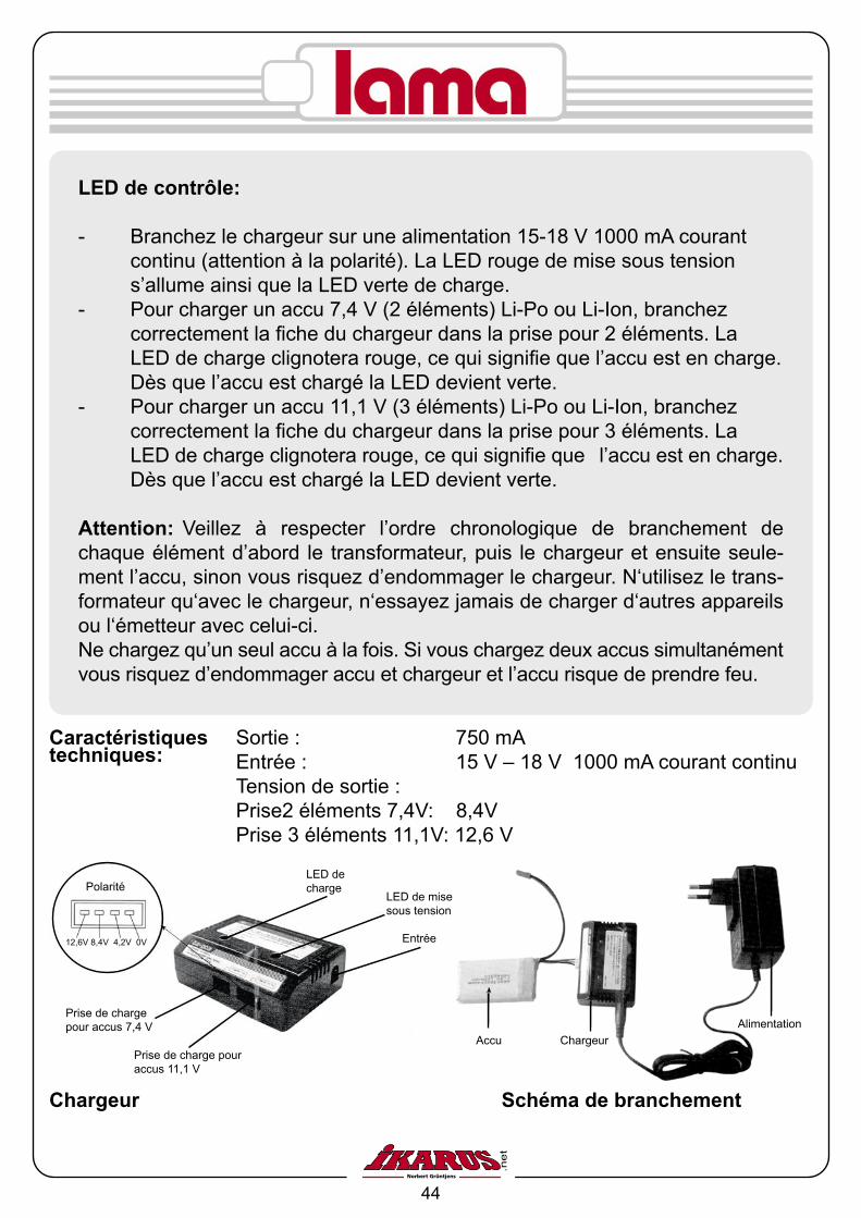
LED de contrôle:
- Branchez le chargeur sur une alimentation 15-18 V 1000 mA courant continu (attention à la polarité). La LED rouge de mise sous tension s’allume ainsi que la LED verte de charge.- Pour charger un accu 7,4 V (2 éléments) Li-Po ou Li-Ion, branchez correctement la fiche du chargeur dans la prise pour 2 éléments. La LED de charge clignotera rouge, ce qui signifie que l’accu est en charge. Dès que l’accu est chargé la LED devient verte.- Pour charger un accu 11,1 V (3 éléments) Li-Po ou Li-Ion, branchez correctement la fiche du chargeur dans la prise pour 3 éléments. La LED de charge clignotera rouge, ce qui signifie que l’accu est en charge. Dès que l’accu est chargé la LED devient verte.
Attention: Veillez à respecter l’ordre chronologique de branchement de chaque élément d’abord le transformateur, puis le chargeur et ensuite seule-ment l’accu, sinon vous risquez d’endommager le chargeur. N‘utilisez le trans-formateur qu‘avec le chargeur, n‘essayez jamais de charger d‘autres appareils ou l‘émetteur avec celui-ci.Ne chargez qu’un seul accu à la fois. Si vous chargez deux accus simultanément vous risquez d’endommager accu et chargeur et l’accu risque de prendre feu.
Sortie : 750 mAEntrée : 15 V – 18 V 1000 mA courant continuTension de sortie :Prise2 éléments 7,4V: 8,4V Prise 3 éléments 11,1V: 12,6 V
Accu ChargeurAlimentation
Caractéristiques techniques:
Polarité
12,6V 8,4V 4,2V 0V
Prise de charge pour accus 7,4 V
Entrée
LED de mise sous tension
LED de charge
Prise de charge pour accus 11,1 V
Chargeur Schéma de branchement
45
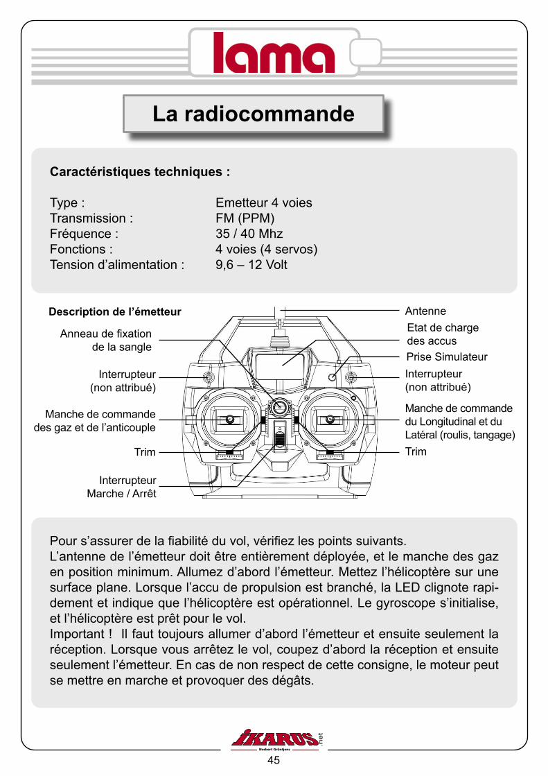
La radiocommande
Antenne
Trim
Manche de commande des gaz et de l’anticouple
Trim
Manche de commande du Longitudinal et du Latéral (roulis, tangage)
Interrupteur (non attribué)
Prise SimulateurInterrupteur
(non attribué)
Etat de charge des accus
Interrupteur Marche / Arrêt
Anneau de fixation de la sangle
Description de l’émetteur
Caractéristiques techniques :
Type : Emetteur 4 voiesTransmission : FM (PPM)Fréquence : 35 / 40 MhzFonctions : 4 voies (4 servos)Tension d’alimentation : 9,6 – 12 Volt
Pour s’assurer de la fiabilité du vol, vérifiez les points suivants.L’antenne de l’émetteur doit être entièrement déployée, et le manche des gaz en position minimum. Allumez d’abord l’émetteur. Mettez l’hélicoptère sur une surface plane. Lorsque l’accu de propulsion est branché, la LED clignote rapi-dement et indique que l’hélicoptère est opérationnel. Le gyroscope s’initialise, et l’hélicoptère est prêt pour le vol.Important ! Il faut toujours allumer d’abord l’émetteur et ensuite seulement la réception. Lorsque vous arrêtez le vol, coupez d’abord la réception et ensuite seulement l’émetteur. En cas de non respect de cette consigne, le moteur peut se mettre en marche et provoquer des dégâts.

46
Lorsque vous déplacez le manche de commande de gauche vers l’avant, les moteurs se mettent en route et l’hélicoptère décolle. Lorsque vous déplacez ce même manche vers la droite, le moteur de l’anti couple va accélérer et l’hélicoptère tournera vers la droite autour de son axe principal. Si vous dé-placez le manche de commande de droite vers l’avant, le plateau cyclique se penchera vers l’avant, l’hélicoptère « piquera » du nez et effectuera une trans-lation vers l’avant.Lorsque ce manche est déplacé vers la droite, le plateau cyclique se penchera vers la droite, et l’hélicoptère engagera un virage sur la droite.Avec les trims, vous pouvez régler le neutre des servos pour éviter par exemple que l’hélicoptère ne chasse de l’arrière.
Exemple: Passage du Mode 2 (d’origine) au Mode 3 (manche de droite: Gaz/ Pas et anti couple, manche de gauche: longitudinal et latéral).
- Retirez d’abord le quartz et le boîtier porte-piles- Devissez le couvercle du boîtier émetteur.- Décrochez le ressort du bloc de commande de droite. - Desserrez un peu les quatre vis du bloc pour retirer plus facilement le renvoi sur lequel est fixé le ressort. - Retirez ensuite ce renvoi et resserrez les quatre vis.- Devissez la lamelle du bloc de gauche et remontez le renvoi ainsi que le res- sort dans le bloc de droite. Le manche de gauche n’est donc plus neutralisé.- Remontez la lamelle sur le bloc de commande de droite.
Changement de Mode
47
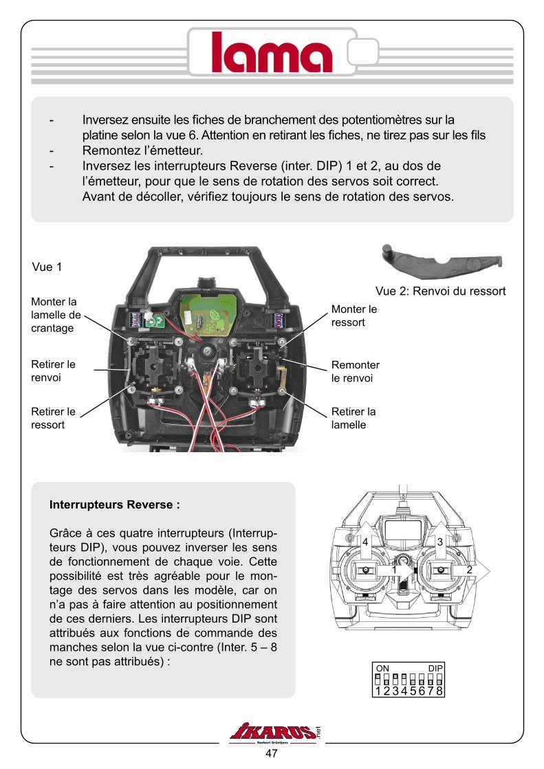
Monter la lamelle de crantage
Retirer le renvoi
Retirer le ressort
Monter le ressort
Remonter le renvoi
Retirer la lamelle
Vue 2: Renvoi du ressort
Vue 1
- Inversez ensuite les fiches de branchement des potentiomètres sur la platine selon la vue 6. Attention en retirant les fiches, ne tirez pas sur les fils- Remontez l’émetteur. - Inversez les interrupteurs Reverse (inter. DIP) 1 et 2, au dos de l’émetteur, pour que le sens de rotation des servos soit correct. Avant de décoller, vérifiez toujours le sens de rotation des servos.
1 2 3 4 5 6 7 8
ON DIP
4
21
3
Interrupteurs Reverse :
Grâce à ces quatre interrupteurs (Interrup-teurs DIP), vous pouvez inverser les sens de fonctionnement de chaque voie. Cette possibilité est très agréable pour le mon-tage des servos dans les modèle, car on n’a pas à faire attention au positionnement de ces derniers. Les interrupteurs DIP sont attribués aux fonctions de commande des manches selon la vue ci-contre (Inter. 5 – 8 ne sont pas attribués) :
48
Latéral / Ailerons
Long
itudi
nal /
pr
ofon
deur
Pas
/ G
az
Anti couple / Direction
Mode 2
+ +
++
1 2 3 4 5 6 7 8
ON DIP
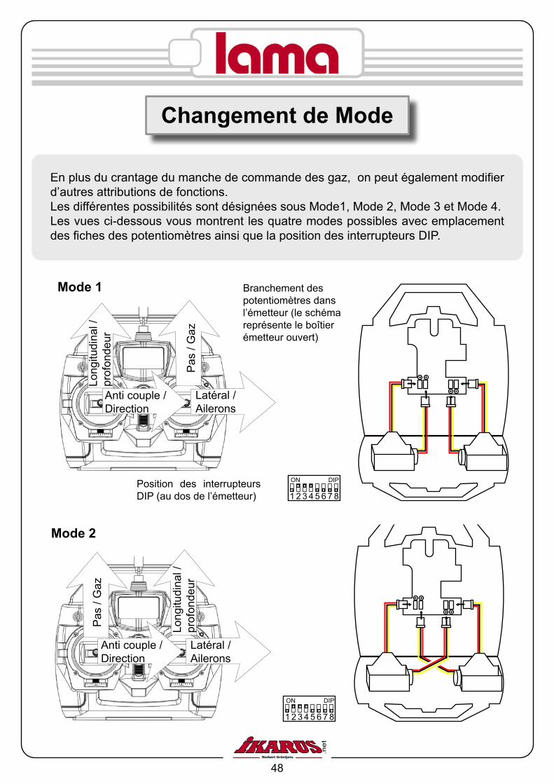
En plus du crantage du manche de commande des gaz, on peut également modifier d’autres attributions de fonctions.Les différentes possibilités sont désignées sous Mode1, Mode 2, Mode 3 et Mode 4.Les vues ci-dessous vous montrent les quatre modes possibles avec emplacement des fiches des potentiomètres ainsi que la position des interrupteurs DIP.
Latéral / Ailerons
Long
itudi
nal /
pr
ofon
deur
Pas
/ G
az
Anti couple / Direction
Mode 1
+ +
++
1 2 3 4 5 6 7 8
ON DIP
Branchement des potentiomètres dans l’émetteur (le schéma représente le boîtier émetteur ouvert)
Position des interrupteurs DIP (au dos de l’émetteur)
Changement de Mode

49
Si vous regardez votre hélicoptère par la gauche, vous verrez deux potenti-omètres sur le récepteur, à l‘intérieur de la cabine, réglables avec le tourne-vis joint. Le potentiomètre supérieur (SENSITIVE) est destiné au réglage de la sensibilité du gyroscope (stabilisation autour de l’axe rotor principal). Si vous le tournez dans le sens des aiguilles d’une montre, vous augmentez la sensibilité du gyroscope. En règle générale, il n’y a rien à modifier à ce niveau là.
Possibilités de réglages sur l’hélicoptère
1 2 3 4 5 6 7 8
ON DIP
Latéral / Ailerons
Long
itudi
nal /
pr
ofon
deur
Pas
/ G
az
Anti couple / Direction
Mode 4
+ +
++
1 2 3 4 5 6 7 8
ON DIP
+ +
++
Latéral / Ailerons
Long
itudi
nal /
pr
ofon
deur
Pas
/ G
az
Anti couple / Direction
Mode 3

50
Les deux condensateurs évitent les interférences dues au frottement des char-bons sur le collecteur. Sans cette mesure d’antiparasitage, on ne peut pas uti-liser le moteur. Soudez les condensateurs comme indiqué sur la vue ci-contre, entre les deux bornes et la masse (corps) du moteur. Grattez le corps du mo-teur à l’endroit de la soudure, pour une meilleure adhérence de l’étain. Soudez maintenant la diode ronde et les cordons d’alimentation. Veillez à ce que le marquage argenté de la diode soit soudé coté pôle Plus du moteur (voir vues) sinon, cela peut endommager l’électronique.
Le moteur principal (Main Motor), est monté à l’arrière du châssis.
Le moteur de l’anti couple (Tail Motor), est monté à l’avant du châssis.
Schéma de branchement
Le pignon est en haut de l’arbre.
Cordon le plus long
Cordon le plus court
Marquage rouge, pôle Moins!
Marquage rouge, pôle Plus!
Le pignon est en bout d’arbre.
Pôle Moins (-)Pôle Plus (+)
Avec le potentiomètre inférieur (EXTEND) vous pouvez augmentez la course des servos (dans le sens horaire) ou la diminuer (en tournant en sens contraire) Si vous augmentez la course des servos, votre hélicoptère réagira plus vite, si vous les diminuez, il sera plus « doux » au pilotage.Attention : Si les débattements sont trop grands, il se peut que le rotor supéri-eur tape dans le rotor inférieur.
Die Motore

51
Manche de gauche vers la gauche
Rotation àgauche
Manche de droite vers la droite
Latéral droit
Manche de droite vers la gauche
Latéral gauche
Manche de droite vers l’arrière
Translation arrière – Freinage
Manche de gauche vers l’avant
Montée
Manche de gauche vers l’arrière
Descente
Manche de droite vers l’avant
Translationavant
Manche de gauche vers la droite
Rotation àdroite
Commande de vol
52
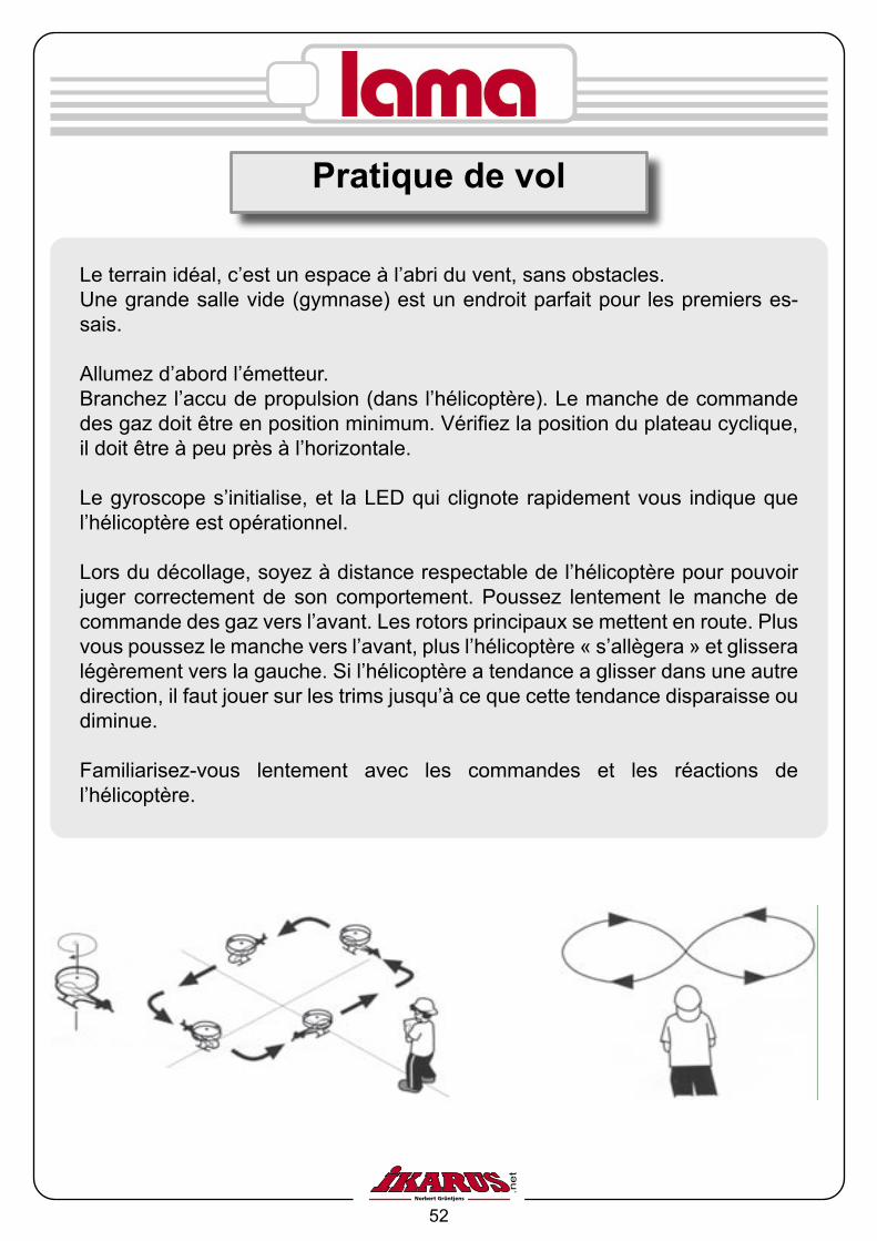
Le terrain idéal, c’est un espace à l’abri du vent, sans obstacles.Une grande salle vide (gymnase) est un endroit parfait pour les premiers es-sais.
Allumez d’abord l’émetteur.Branchez l’accu de propulsion (dans l’hélicoptère). Le manche de commande des gaz doit être en position minimum. Vérifiez la position du plateau cyclique, il doit être à peu près à l’horizontale.
Le gyroscope s’initialise, et la LED qui clignote rapidement vous indique que l’hélicoptère est opérationnel.
Lors du décollage, soyez à distance respectable de l’hélicoptère pour pouvoir juger correctement de son comportement. Poussez lentement le manche de commande des gaz vers l’avant. Les rotors principaux se mettent en route. Plus vous poussez le manche vers l’avant, plus l’hélicoptère « s’allègera » et glissera légèrement vers la gauche. Si l’hélicoptère a tendance a glisser dans une autre direction, il faut jouer sur les trims jusqu’à ce que cette tendance disparaisse ou diminue.
Familiarisez-vous lentement avec les commandes et les réactions de l’hélicoptère.
Pratique de vol
53
Le rotor ne démarre pas
- Pour des raisons évidentes de sécurité, le manche de commande des gaz ainsi que son trim doivent être en position minimum. Si ce n’est pas le cas, le moteur ne démarrera pas. Attendez quelques secondes, jusqu’à ce que la LED verte ne clignote plus et qu’elle reste allumée en permanence. Pendant ce temps, ne bougez pas les manches de commande.- L’accu est vide, il faut recharger l’accu
Les moteurs démarrent, mais les rotors ne tournent pas
- Vérifiez si les pignons sont en bien en prise. Si ce n’est pas le cas, desserrez les vis de fixation du moteur, rapprochez le moteur du pignon puis resserrez les vis de fixation du moteur.
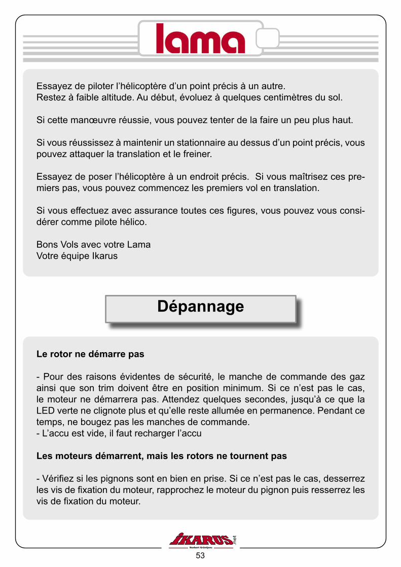
Essayez de piloter l’hélicoptère d’un point précis à un autre.Restez à faible altitude. Au début, évoluez à quelques centimètres du sol.
Si cette manœuvre réussie, vous pouvez tenter de la faire un peu plus haut.
Si vous réussissez à maintenir un stationnaire au dessus d’un point précis, vous pouvez attaquer la translation et le freiner.
Essayez de poser l’hélicoptère à un endroit précis. Si vous maîtrisez ces pre-miers pas, vous pouvez commencez les premiers vol en translation.
Si vous effectuez avec assurance toutes ces figures, vous pouvez vous consi-dérer comme pilote hélico.
Bons Vols avec votre Lama Votre équipe Ikarus
Dépannage

54
Pièces de rechange
Pal
es d
e ro
tor
# 69
9300
2B
arre
de
Bel
l#
6993
001
Axe
prin
cipa
l, in
térie
ur#
6993
007
Acc
u Li
Po
800
mA
7,4
V#
6993
021
Sup
port
de p
ales
# 69
9300
3
Réd
ucte
ur#
6993
009
Pow
erbo
ard
# 69
9302
2
Pla
teau
cyc
lique
# 69
9300
4
Trin
gle
# 69
9300
5
Axe
prin
cipa
l ex
térie
ur#
6993
008
Mot
oeur
# 69
9302
0
Ant
i cou
ple
# 69
9301
2
Gui
de p
late
au
cycl
ique
# 69
9300
6
Ent
raîn
men
t pl
atea
u#
6993
010
Sup
port
accu
# 69
9301
5
Ser
vo (1
pce
)#
6993
019
Cha
rgeu
r LiP
o#
6993
023
Châ
ssis
# 69
9301
1R
otul
es A
lum
iniu
m
# 69
9301
4Vi
sser
ie
#
6993
016
Rou
lem
ents
# 69
9301
7E
met
teur
...Q
uartz
... w
ww
.ikar
us.n
et.
Verr
ière
# 69
9301
8
Trai
n ďa
tteris
sage
# 69
9301
3

55
1. Cet hélicoptère n’est pas un jouet.Pour le montage et par la suite en vol, un minimum de connaissances sont requi-ses. Des erreurs au cours du montage peuvent avoir de graves conséquences Etant donné que ni le fabricant ni le revendeur peuvent vérifier le montage correct de l’appareil et encore moins son utilisation en vol, nous ne pouvons qu’attirer votre attention sur ce fait.
2. Suivez scrupuleusement les notices de montage et d’utilisation. Des modifications de montage et le non respect de la notice d’utilisation peuvent faire sauter la garan-tie.
3. Même un modèle monté correctement peut être dangereux. Ne jamais mettre les mains dans un rotor qui tourne ou les doigts sur des pièces en mouvement, ris-que de blessures graves.
4. En règle générale, tout modéliste doit avoir un comportement responsable pour ne pas mettre autrui en danger ou troubler l’ordre public.
N’utilisez que des accus avec le nombre d’éléments et capacité conseillé. Si le nombre d’éléments de l’accu est trop important, le moteur peut s’emballer, surchauffer, prendre feu, et provoquer des perturbations au niveau de la radiocom-mande.Les pales de rotor, plus particulièrement leur fixation peuvent céder et les pièces peuvent voler dans tous les sens à très grande vitesse.Un nombre d’élément trop faible peut également engendré des interférences.N’utilisez que des accus chargés. Posez votre modèle avant que les accus ne soient complètement vides pour éviter tout dysfonctionnement qui pourrait provoquer le crash du modèle.Avant chaque vol, vérifier le bon fonctionnement de l’ensemble radiocommande. Les gouvernes doivent débattre dans le bon sens.
Avant d’allumer la radio, vérifiez que votre fréquence est bien libre.
Assurez-vous que personne ne soit sur la piste lorsque vous décollez. En Vol, ne perdez jamais votre modèle de vue
Consignes de sécurité

56
GewährleistungFür dieses IKARUS Produkt übernehmen wir eine Gewährleistung im Rahmen der gesetzlichen Bestimmungen (zur Zeit 24 Monate, Stand 2006), weitere Ansprüche, z. B. bei Folgeschäden, sind komplett ausgeschlossen. Als Beleg für den Beginn und den Ablauf dieser Gewährleistung dient der Kaufbeleg. Eventuelle Reparaturen verlängern den Gewährleistungszeit-raum nicht. Reparatureinsendungen bitte an die unten angegebene Adresse. Bei Einsendung eines Gerätes, das sich nach der Eingangsprüfung als funktionsfähig herausstellt, erheben wir eine Bearbeitungsgebühr von 20,- €. Für Schäden, die beim Transport Ihrer Zusendung erfolgen, übernehmen wir keine Haftung. Auch der Verlust Ihrer Sendung ist von der Haftung durch uns ausgeschlossen.Bei Rückfragen und technischen Problemen nutzen Sie unsere Service-Hotline unter der Telefonnummer 09001 – 79 50 20 (Erreichbar von Montag bis Freitag in der Zeit von 8.00 bis 17.00 Uhr; 0,99 €/ Min.)
–Zertifikat abrufbar unter: http://www.ikarus-modellbau.de/Anleitungen/Lama.pdf Produkt in Einklang mit FTEG und R&TTE Directive 1999/5/EC
Warranty termsWe warrant the IKARUS product within the European Union for a period of 24 months. We warrant the IKARUS product in North America for a period of 3 months. For further North America warranty informa-tion, please go to www.ikarus-usa.com and click on „Business Terms“.Your sales receipt is evidence of the start and finish of the warranty period. Any repairs do not extend the warranty peri-od. If any functional, manufacturing or material defects become evident during the warranty period we will rectify them. Further claims, e.g. subsequent damage or loss are strictly excluded. Please, send repairs to the address listed below. There will be a 20.00 € / 21.00 US$ service charge (plus return shipping charges) for repair items, which turn out to be in perfect condition. Postage must be paid for; the return shipping will also be paid for. Shipments arriving postage collect will not be accepted. We do not accept any liability for damage or loss during inbound transport. If you are a customer living in Germany and have questions and technical problems, please use our Service Hotline phone number 09001-795020 (Monday through Friday from 8.00 to 17.00 MEZ; € 0.99/min.). North American customers please call 239-690-0003 (Monday through Friday 8.00 am to 4.30 pm EST)
-Certificate: http://www.ikarus-modellbau.de/Anleitungen/Lama.pdfEquipment in accordance with the FTEG und R&TTE Directive 1999/5/EC
Conditions de garantieNous offrons une garantie de 24 mois pour le produit IKARUS. La date du ticket de caisse est la date du début de la garantie. D’éventuelles réparations ne prolongent pas cette durée. Si pendant cette période, des défauts matériels ou de fabrication ainsi que des ratés au niveau fonctionnel surviennent, nous les réparerons. Tout autre problème comme par ex. des dégâts consécutifs ne sont pas couverts. Envoyez l’article défectueux à l’adresse indiquée. Votre envoi doit être affranchi par vos soins, de même que l’envoi de retour le sera par nos soins. Tout article retourné pour réparation dont le fonctionnement s’avère correct après contrôle, fera l’objet d’une facturation forfaitaire de 20,- €. Les envois non affran-chis ne peuvent pas être acceptés. Nous ne sommes pas responsables des dommages survenant pendant le transport de votre paquet. De même en cas de perte du colis. Pour toute réclamation ou commande de pièces de rechange, veuil-lez contacter l’une des adresses suivantes.
-Certificate: http://www.ikarus-modellbau.de/Anleitungen/Lama.pdfEquipment in accordance with the FTEG und R&TTE Directive 1999/5/EC
www.ikarus.net
Im Webertal 2278713 Schramberg-WaldmössingenBestelltelefon: ++49 (0) 74 02 - 92 91-90Hotline: (0,99 €/Min.) ++49 (0) 900 1 - 79 50 20Fax: ++49 (0) 74 02 - 92 [email protected]
IKARUS France57, Rue de Phalsbourg67260 Sarre-UnionTel. (+33)0 388 01 10 10Fax: (+33)0 388 01 11 [email protected]
5876 Enterprise ParkwayBilly Creek Commerce CenterFort Myers, FL 33905Phone +1-239-690-0003Fax +1 [email protected]