Embed Size (px)
Citation preview
c
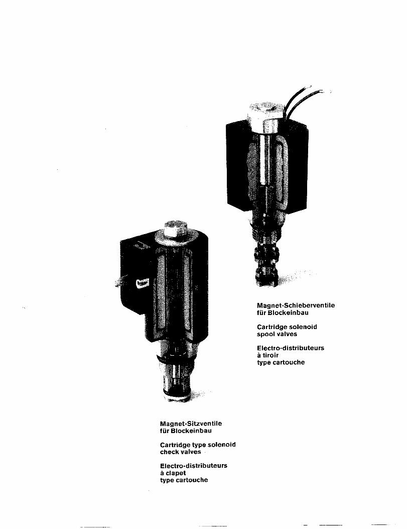
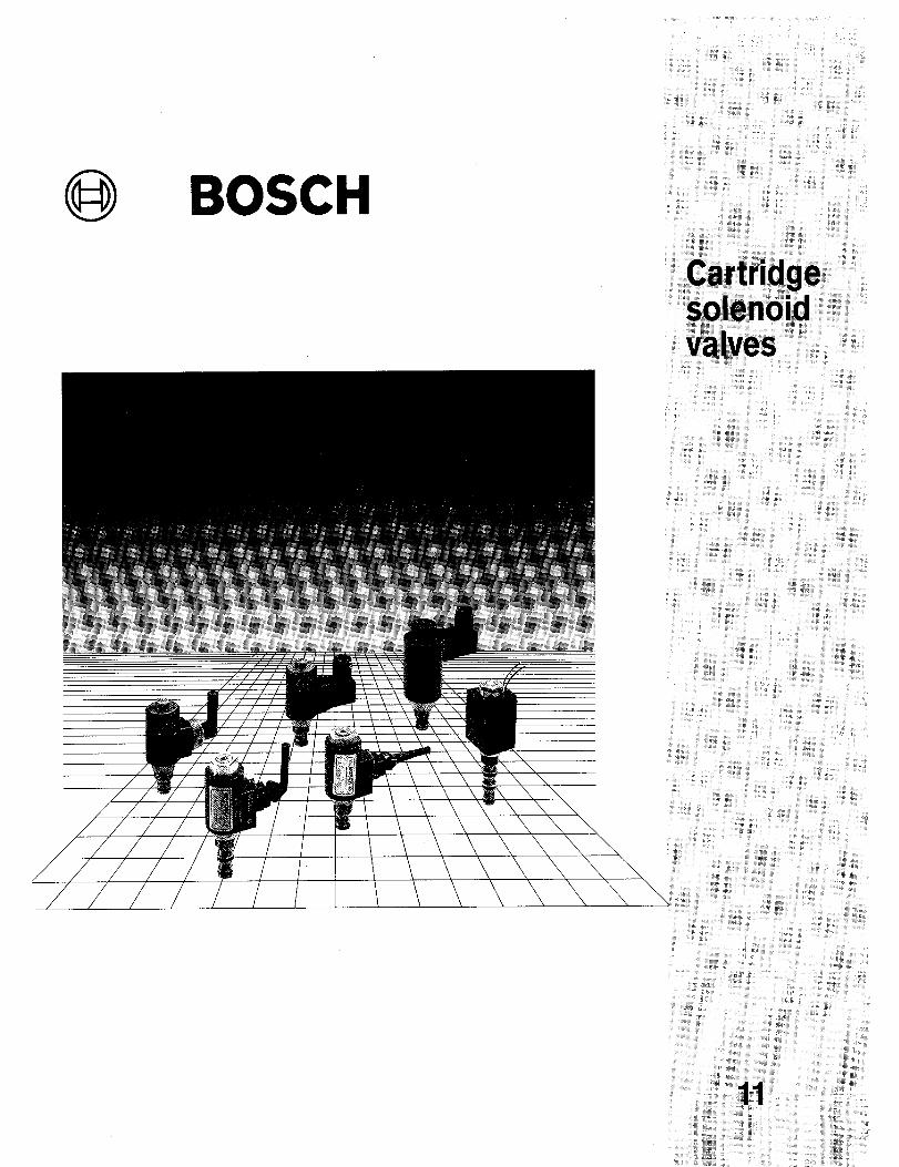
Magnet-Sitzventilefur Blockeinbau
Cartridge type solenoidcheck va Ives
Magnet-Schieberventifur Blockeinbau
Cartridge solenoidspool valves
Electro-distributeursa tiroirtype cartouche
ile
Electro-distributeursa clapettype cartouche
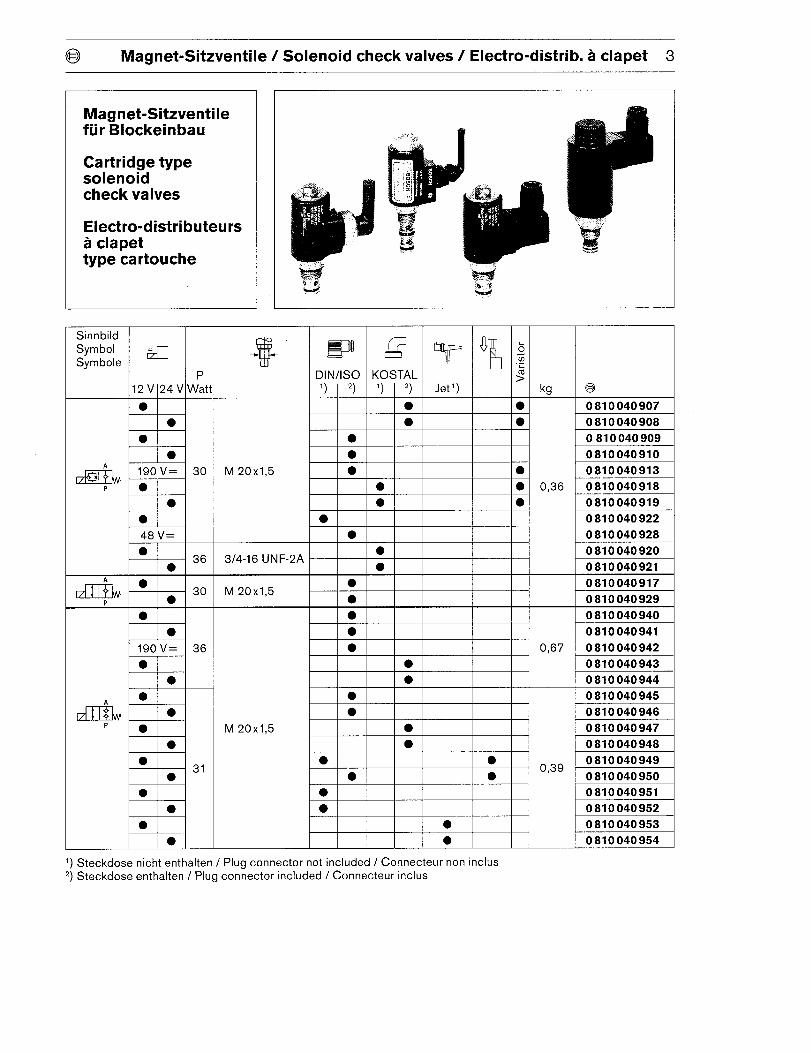
@ Magnet-Sitzventile / Solenoid check valves/ Electro-distrib. a clapet 3
Magnet-Sitzventilefur Blockeinbau
Cartridge typesolenoidcheck valves
Electro-distributeursa clapettype cartouche
zP
z5z>
●
●
o●
●
—————.
—
—
Sinnbild
Symbol
Symbole
EKOSTAL
‘) 2,
+
●
●
12 V124 V\Wat
*
Jet’)
s
kg
0,36
●
●
●
●
M 20xI,5 ●w 190 v=
●
●
●
30
*
●
●
P
0 810 040 907
0 810 040 908
0 810 040 909
0 810 040 910
0 810 040 913
0 810 040 918
0 810 040 919
0 810 040 922
0 810 040 928
0 810 040 920
0 810 040 921
0 810 040 917
0 810 040 929
0 810 040 940
0 810 040 941
●
●3/4-16 UNF-2A l------+
-●
●30
●
●
190 V= 36
●
●
DEI ● 0,67
0,39
0 810 040 942
0 810 040 943
0 810 040 944
0 810 040 945
0 810 040 946
0 810 040 947
0 810 040 948
0 810 040 949
0 810 040 950
0 810 040 951
●
●
I
●
●
M 20x1,5
I 1
31I
0 810 040 9520 810 040 9530 810 040 954
‘) Steckdose nicht enthalten / Plug connector not included / Connecter non inclus2 Steckdose enthalten / Plug con;ector included / Connecter inclusj
4 Magnet-Sitzventile / Solenoid check valves/ Electro-distrib. a clapet @
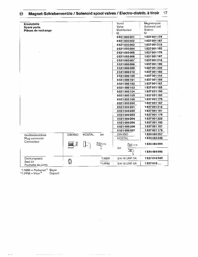
ErsatzteileSpare partsPieces de rechange
GeratesteckdosePlug connectorConnecter
1 834 484 094
1 834 484 095
DichtungssatzSet of sealsPochette de ioints
DIN/lSO KOSTAL Jet
E9W)T
Ventil Magnetspu[eValve Solenoid coilDistributeur Bobine(’@ (@)
0 810 040 907 1 837 001 123
0 810 040 908 1 837 001 133
0 810 040 909 1 837 001 134
0 810 040 910 1 837 001 135
0 810 040 913 1 837 001 136
0 810 040 918 1 837 001 123
0 810 040 919 1 837 001 133
0 810 040 922 1 837 001 134
0 810 040 928 1 837 001 199
0 810 040 920 1 837 001 152
0 810 040 921 1 837 001 151
0 810 040 917 1 837 001 134
0 810 040 929 1 837 001 135
0 810 040 940 1 837 001 174
0 810 040 941 1 837 001 175
0 810 040 942 1 837 001 176
0 810 040 943 1 837 001 177
0 810 040 944 1 837 001 178
0 810 040 945 1 837 001 194
0 810 040 946 1 837 001 195
0 810 040 947 1 837 001 200
0 810 040 948 1 837 001 201
0 810 040 949 1 837 001 194
0 810 040 950 1 837 001 195
0 810 040 951 1 837 001 194
0 810 040 952 1 837 001 195
0 810 040 953 1 837 001 191
0 810 040 954 1 837 001 218
DIN/lSO 1 834 484 057
KOSTAL 1 834 484 046
1 817 010 272
3/4-16 UNF-2A \ 1 817 010 281 I
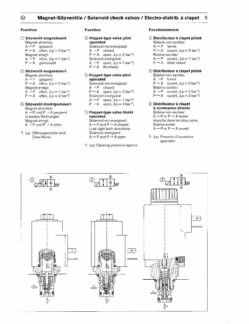
@ Magnet-Sitzventile / Solenoid check valves/ Electro-distrib. a clapet 5
Funktion
@ Sitzventii vorgesteuertMagnet stromlos:
A + P gesperrtP+A offen, Ap=2 bar*)
Magnet erregt:A+P offen, Ap=l bar*)
P + A gedrosselt
@ Sitzventil vorgesteuert
Magnet stromlos:
A + P gesperrt
P+A offen, Ap=2 bar*)
Magnet erregt:A+ P offen, Ap= 1 bar*)
P+A offen, Ap= 2 bar*)
@ Sitzventil direktgesteuertMagnet stromlos:
A + P und P + A gesperrt
in beiden RichtungenMagnet erregt:A+ Pund P+ Aoffen
*) Ap: Offnungsdrucke sind
Zirka-Werte
Function
(I) Poppet-type valve pilotoperatedSolenoid not energized:
A + P closedP-A open, Ap=2 bar*)
Solenoid energized:A+P open, Ap=l bar*)
P + A throttled
@ Poppet-type valve pilot
operated
Solenoid not energized:A + p closed
P+A open, Ap= 2 bar*)
Solenoid energized:A+ P open, Ap= 1 bar*)
P+A open, Ap= 2 bar*)
@ Poppet-type valve direkt
*)
operatedSolenoid not energized:A+ Pand P+ A closed,
Leak tight both directions.
Solenoid energized:A+ Pand P+ Aopen
A p: Opening pressure approx.
Fonctionnement
@ Distributeur a clapet piloteBobine non excitee:A + p ferm~
P + A ouvert, A p = 2 bar*)
Bobine excitee:
A + P ouvert, A p = 1 bar*)p+ A debit r~duit
@ Distributeur a clapet piloteBobine non excitee:
A + P fermeP+A ouvert, Ap = 2 bar*)
Bobine excitee:
A + P ouvert, Ap = 1 bar*)p+A ouvert, Ap = 2 bar*)
@ Distributeur a clapeta commande directeBobine non excitee:A+ Petp+Aferm@
etanche clans Ies deux sens.Bobine exitee:A+ Petp+Aouvert
*) A p: Pression d’ouverture
approxim.
?
(1’
I -4—
I!!lP
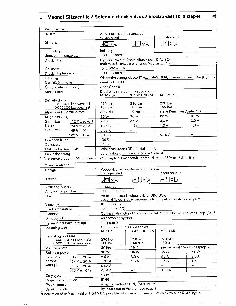
6 Magnet-Sitzventile / Solenoid check valves/ Electro-distrib. a clapet @
Kenngro13en
Bauart Sitzventil, elektrisch betatigtvorgesteuert direktgesteuert
Sinnbild+L Il+k II$IW
Einbaulage beliebig
Umgebungstemperatur –30... +6O”C
Druckmittel Hydraulikole auf Mineralolbasis nach DIN/lSO;
andere, z. B. umweltschonende Medien auf Anfrage
Viskositat 10...500 mm2/s
Druckmitteltemperatur -30... +80°C
Filterung Olverschmutzung Klasse 10 nach NAS 1638, zu erreichen mit Filter ~2~ =75
Durchflul%ichtung gemaB Sinnbild
Offnungsdruck (Feder) siehe Seite 5
Anschlu13art Blockeinbau mit Einschraubgewinde
M 20x1,5 3/4-16 UNF-2A M 20xI,5
Betriebsdruck500000 Lastwechsel 270 bar 210 bar 270 bar
10000000 Lastwechsel 160 bar 160 bar 160 bar
Maximaler Durchflu13strom 30 l/rein 15 l/rein siehe Kennlinen (Seite 7, 8)
Magnetleistung 30 w 36 W 36 W 31 w
Strom bei 12 V*20Y0’) 2,5 A 3,o A 3,o A 2,6 A
Nenn- 24 V ~ 200/0 1,25 A 1,5A 1,5A 1,3Aspannung 48 V * 20 ‘/o 0,63 A — —
190vt loo/o 0,16A — 0,19A —
Einschaltdauer 1000/0’)
Schutzart 1P 65
Elektrischer Anschlu13 Winkelsteckdose DIN, Kostal oder Jet
Funkenloschung durch integrierten Varistor (siehe Seite 3)
‘) Ansteuerung des 12-V-Magneten mit 24 V moglich. Einschaltdauer reduziert auf 25 O/obei Zyklus 5 min.
Specifications
Design Poppet-type valve, electrically operated
pilot operated direct operated
Symbol+L lI+L H$L
Mounting position as desired
Ambient temperature –30... +6O”C
Fluid Petroleum-based hydraulic fluid (DIN/lSO);
optional fluids, e.g., environmentally-compatible media, on request
Viscosity 10,..500 mm’/s
Fluid temperature -30 ...+80°C
Filtration Contamination class 10, accord. to NAS 1638 to be realized with filter (J,. Z 75
Direction of flow As shown on symbol
Opening pressure (Spring) see page 5
Mounting type Cartridge with threaded socketM 20x1.5 3/4-16 UNF-2A I M 20x1.5
1
Operating pressure500000 load reversals 270 bar 210 bar 270 bar
10000000 load reversals 160 bar 160 bar 160 bar
Solenoid-power 30 w
Current at 12 V*20V0’) I 2.
nominal 24 V+ 200/0
nin 15 l/rein see performance curves (page 7, 8)Maximum flow 30 I/nI
36 W 36 W 31 w
.5A 3.0 A 3.0 A 2.6 A
1.25A 1,5A 1.5A 1.3Avoltage 48 V ~ 200/0 0.63 A
19 OV*1OVO 0.16A — 0.19A —l– I
Duty cycle 1000/0’)
Degree of protection 1P 65
Power supply Plug connector to DIN, Kostal or Jet
Spark quenching by incorporated Varistor (see page 3)
1) Activation of 12 V solenoid with 24 V DC possible with operating time reduction to 25 ‘/o on 5 min. cycle.
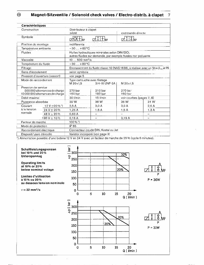
@ Magnet-Sitzventile / Solenoid check valves/ Electro-distrib. a clapet 7
Caracteristiques
Construction
Symbole
Position de montage
Temperature ambiante
Fluides
Viscosite
Temperature du fluide
Filtrage
Sens d’ecoulement
Pression d’ouverture (ressort)
Mode de raccordement
Pression de service500000 alternancesde charge
10000 OOOalternances de charge
Debit maximal
Puissance absorbee
Courant 12 V*20V0’)
a la tension 24 V+ 200/0normale
48 V* 200/0
19 CIV*1OVO
Facteur de marche
Mode de protection
Raccordement electrique
Dispositif pare etincelle
Distributeur a clapet
pilote commande directe
w+ WV H$Lindifference
-30.,. +60°C
Huiles hydrauliques minerales selon DIN/lSO;
autres fluides sur demande, par exemple fluides non polluants
10,..500 mm2/s
–30... +80°C
Encrassement du fluide classe 10 (NAS 1638), a realiser avec un filtre (325>75
selon svmbole
voir ~aae 5
Type cartouche avec filetage
M 20x1,5 3/4-16 UNF-2A I M 20xI,5
270 bar 210 bar 270 bar160 bar 160 bar 160 bar
30 l/rein 15 l/rein voir courbes (pages 7, 8)
30 w 36 W 36 W 31 w
2,5 A 3,0 A 3,0 A 2,6 A
1,25A 1,5A 1,5A 1,3A
0,63 A I — 1- 1-O,16A — 0,19A —
1000/0’)
1P 65
Connecter coude DIN, Kostal ou Jet
Varistor incorpore (voir page 3)
1, Alimentation possible d’une bobine 12 V en 24 V avec un facteur de marche de 25V0 (cycle 5 minutes).
Schaltleistungsgrenzenbei 10VO und 20%0Unterspannug
Operating limitsat 109Aoor 200/0below nominal volage
Limites d’utilisationa 10 YOOU 20V0au dessous tension nominale
v = 32 mm2/s
A
! 300a. 10%
4250 \
200 \
15020%
100
50
0 Eo 5 10 15 20
Q [ l/rein 1
k A
f 300CL4 250 \ \
200.10%
150 20%
100
50
0 E
ii
H$LP
P = 36W
P
P = 31W
o 5 10 15 20Q [ l/rein 1
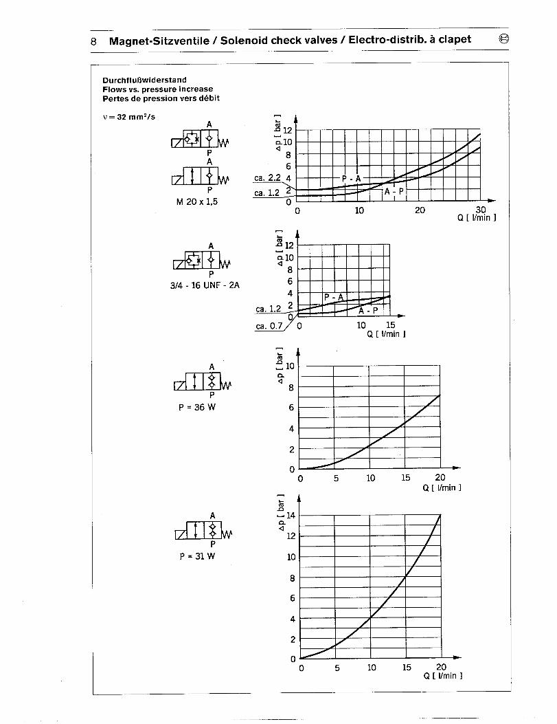
8 Magnet-Sitzventile / Solenoid check valves/ Electro-distrib. a clapet @
DurchflubwiderstandFlows vs. pressure increasePertes de pression vers debit
v=32 mm2/sA
PA
H+’LP
M 20 X 1,5
A
P314-16 UNF - 2A
A
H$LP
P=36W
A
H$LP
P=31W
o 10
—,
212~10
86
4 -
/n
Ca. 0.770 10 15Q [ l/rein 1
1
6
4
2
0
20Q [ I?m!n 1
A
A ‘
/F
o 5 10 15 20Q [ l/rein 1
,
@ Magnet-Sitzventile / Solenoid check valves/ Electro-distrib. a clapet 9
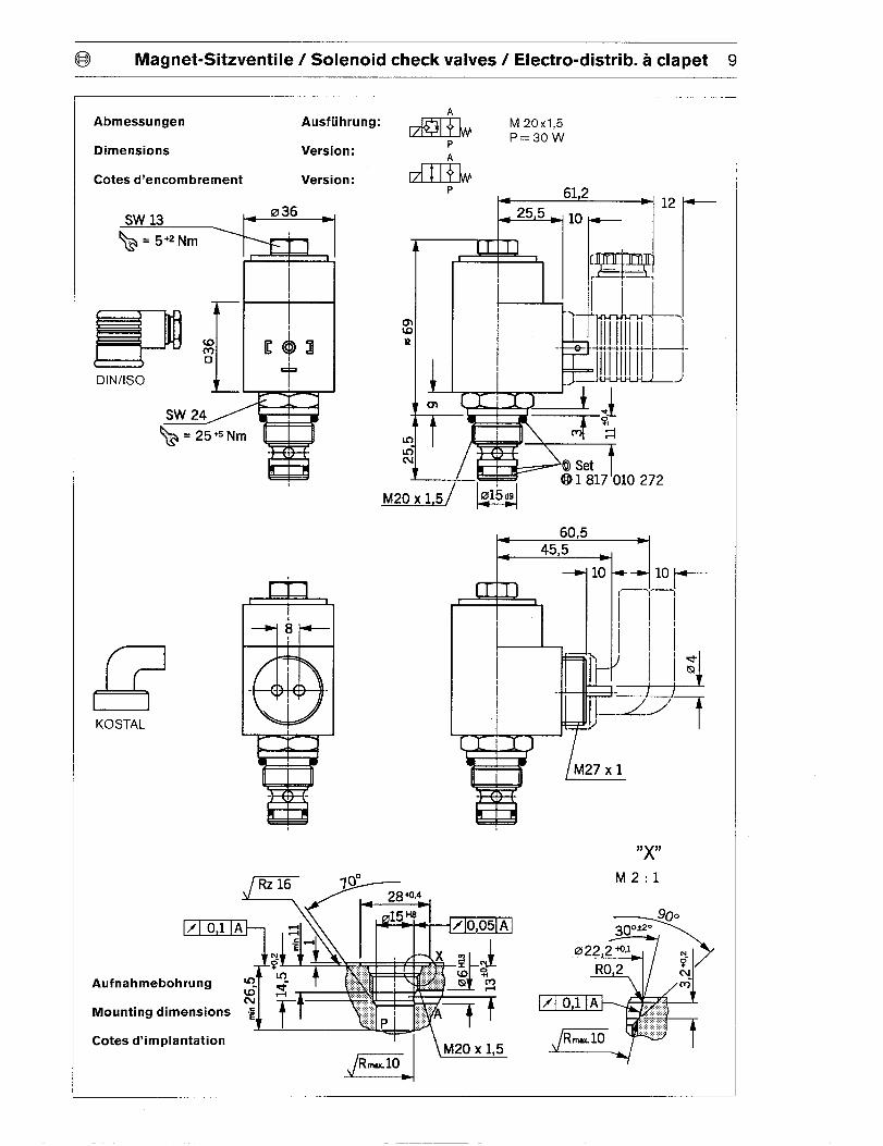
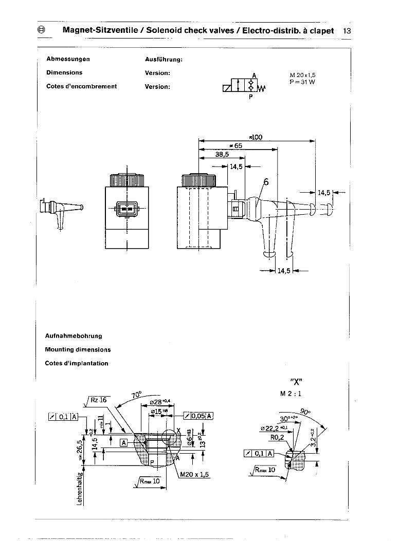
Abmessungen
Dimensions Version:
Cotes d’encombrement Version:
1 817 010 272
KOSTAL
IW
Aufnahmebohrung
Mounting dimensions
Cotes d’implantation
t
P
10
‘/
l /M27 X 1
“x”
mu.
M2:1
@
>
3f30&?.
*
0222 +QJ
R0,2?mlm-
)f O 1 A .,..<:.,
Rmax10 ““‘‘“:
v
10 Magnet-Sitzventile / Solenoid check valves/ Electro-distrib. a clapet @
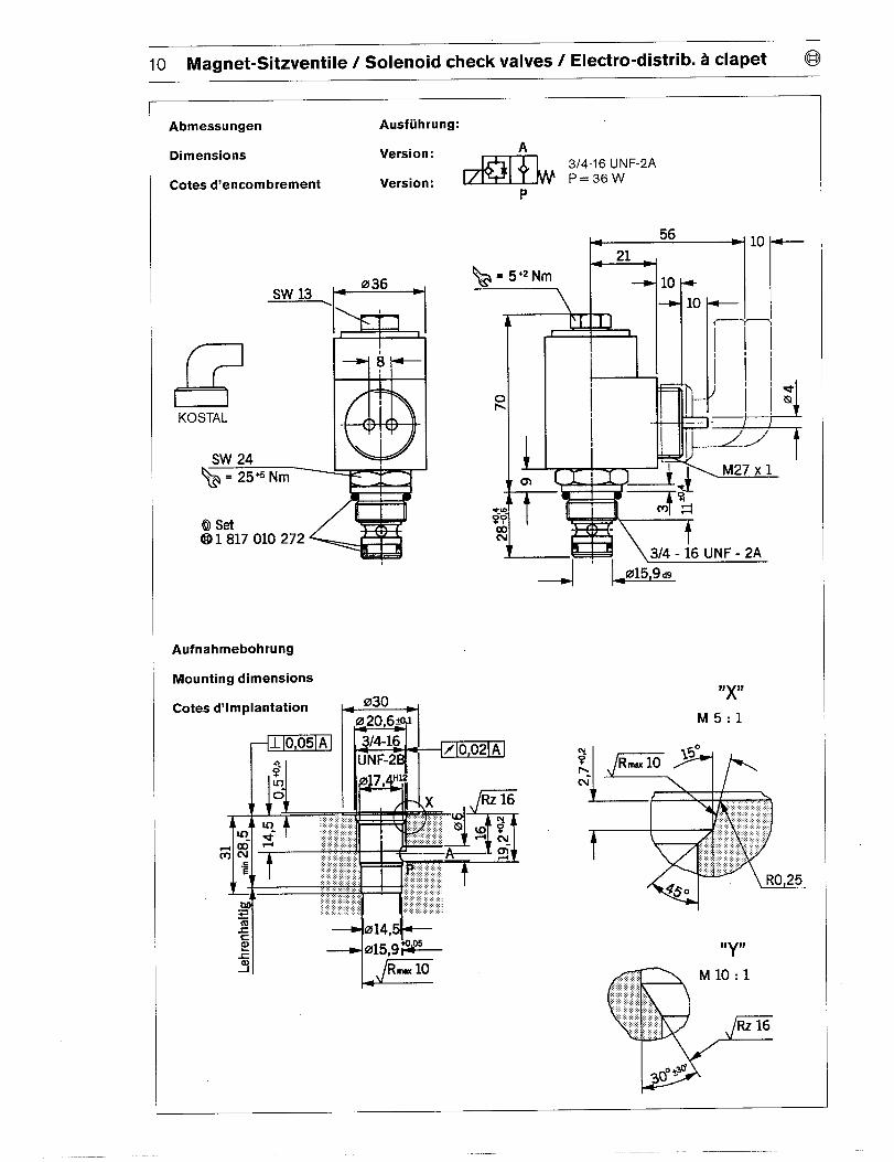
Abmessungen Ausfuhrung:
Dimensions Version:A
3/4-16 UNF-2A
Cotes d’encombrement Version: P=36W
P
t-56 +loe
ril
1 817 010 272.+, \3/4 - i6 UNF - 2A
Aufnahmebohrung
Mounting dimensions
Cotes d’implantation ~ 030 d
%~c
&-3 Rmx 10
@ Magnet-Sitzventile / Solenoid check valves/ Electro-distrib. a clapet 11
Abmessungen Ausfuhrung:
ADimensions Version:
ll$kM 20x1,5P=36W
Cotes d’encombrement Version: P
x k 65,2 d
IQmN
KOSTAL
mlI I SW 27
1 817 010 272
,,:,
1 I
49,5
Au fnahmebohrung:
+Seite 9 ‘
Mounting dimensions: Page 9
f I!
k 63,5●
—.
10
Cotes d’implantation: Page 9
12 Magnet-Sitzventile / Solenoid check valves/ Electro-distrib. a clapet @
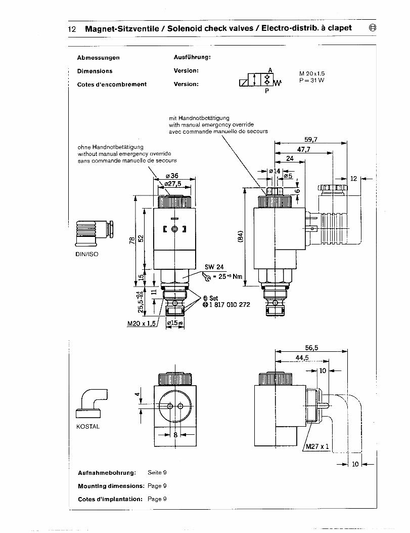
Abmessungen Ausfuhrung:
Dimensions Version:
Cotes d’encombrement Version:
AM 20x1,5P=31W
P
mit Handnotbetatigung
with manual emergency override
avec commande manuelle de secours
ohne Handnotbetatigungwithout manual emergency override
saris commande manuelle de secours
DIN/lSO
1 817 010 272
KOSTAL
’ -
+
10
~ ~ -T.. ,
1 4
1-=- ‘\ ‘\
1 FE b’ , ,
1 1
‘l_lO-’L
I-
Au fnahmebohrung: Seite 9
Mounting dimensions: Page 9
Cotes d’implantation: Page 9
@ Magnet-Sitzventile / Solenoid check valves/ Electro-distrib. a clapet 13
Abmessungen Ausfuhrung:
Dimensions Version:
Cotes d’encombrement Version:
I
II
A M 20x I,5
I P=31W
l--
ir- --f111
I ,1
Ill
Ill
L— —-I
14,5t-
+
Aufnahmebohrung
Mounting dimensions
Cotes d’implantation
r. .
-1
TI
I
L
4,5 L
J,)(H
M2:1
goo
>
300+20
a
0222 WJ m.
RO 2?N-m
7 01 A ;:,,:~j;,.......
Rm 10 ‘i;’xw
14 Magnet-Sitzventile / Solenoid check valves/ Electro-distrib. a clapet @
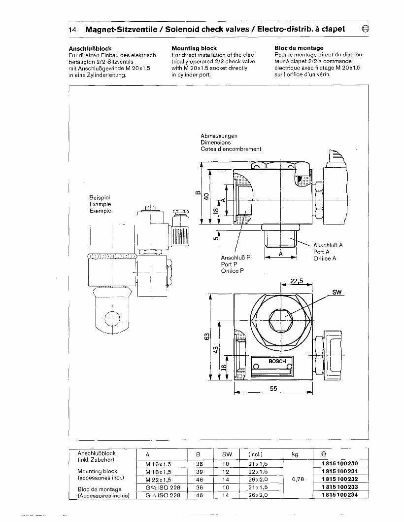
AnschluBblock Mounting block Bloc de montage
Fur direkten Einbau des elektrisch For direct installation of the elec- Pour Ie montage direct du distribu-
betatigten 2/2-Sitzventils trically-operated 2/2 check valve teur a clapet 2/2 a commande
mit Anschlu13gewinde M 20x1,5 with M 20x1.5 socket directly electrique avec filetage M 20x1,5
in eine Zylinderleitung. in cylinder port. sur I’orifice d’un verin.
Beispiel
AbmessungenDimensions
Cotes d’encombrement
i=%
‘A Port A
Anschlu13 P Orifice APort POrifice P
22,5
55
Anschlu13block A B Sw (incl.)(inkl. Zubehor)
M16x1,5 36 10 21 x1,5 1 815 100 230
Mounting block M18x1,5 39 12(accessories incl.)
22x1,5 1 815 100 231
M22x1,5 46 14 26x2,0 0,78 1 815 100 232
1 815 100 233
1 815 100 234Bloc de montage
G3/8 lSO 228 I 36 10 21 x1,5
(Accessoires inclus) G 1/2 ISO 228 ( 46 14 26x2,0
lkgl@ I
@ Magnet-Schieberventile / Solenoid spool valves/ Electro-distrib. a tiroir 15
Magnet-Schieberventilefur Blockeinbau
Cartridge solenospool valves
d
Electro-distrib uteursa tiroirtype cartouche
Sinnbild
Symbol
Symbole
2/2
212
CzEI&
[bar] [Ilminl 12 V124V148V Watt
210 20 ● 35 ●
DIN/ KOSTAL1s0
210 20 ● 35 ● ●
210 20 ● 35 ● ● ●
30 20 ● 15 ● ●
30 20 ● 15 3/4-16 ● ●
210 20 ● 35 UNF ● ●
30 20 ● 15 ● ●
30 20 ● 15 ● ●
210 10 ● 30 c ●
210 10 ● 30 ● ●
210 20 ● 3.5 ● ●
30 20 ● 15 ● ●
0 521 000 001
0 521 000 006
B 534 030 024
B 534 030 041
B 534 030 042
B 534 030 054
B 534 030 069
B 534 030 070
B 534 030 071
B 534 030 072
B 521 000 002
0 521 000 004
0 521 000 005
0 521 000 007
0 521 000 008
0 521 000 009
0 521 000 010
B 534 030 004
210 20 ● 35 ● ●
120 6 ● 30 ● ●
30 20 ● 15 ● ●
30 20 ● 15 ● ●
210 20 ● 35 3/4-1 6 ● ●
30 20 ● 15 UNF ● ●
30 90 ● 15 ● ●B 534 030 030B 534 030 062B 534 030 063B 534 030 068B 534 030 081
*) NBR = Perbunan @ Bayer
*’) FPM = Viton @ Dupont
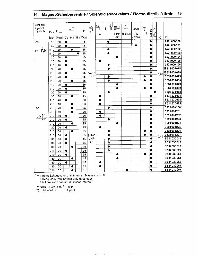
16 Magnet-Schieberventile / Solenoid spool valves/ Electro-distrib. a tiroir @
Sinnbild
Symbol
Symbole Pnlax. %.x.K , ~ T d w ~ - ok . =
Jet DINI KOSTAL DINccp
$Q.
I[bar] [Ilmin] 12V 24V 48V Watt [s0 46244 ‘ L kg
30 20 ● 15 ● ●
30 20 ● 15 ● ●
210 20 ● 35 ● ●
210 20 ● 35 ● ●
30 20 ● 15 ● ●
30 20 ● 15 ● ●
●
●
I z,”, 1“ I
0 521 000 100
0 521 000 101
0 521 000 102
0 521 000 103
0 521 000 104
0 521 000 105
0 521 000 106
B 534 030 018
B 534 030 020
B 534 030 025
B 534 030 034
B 534 030 049
B 534 030 050
B 534 030 058
B 534 030 073
B 534 030 074
B 534 030 075
0 521 000 200
0 521 000 201
0 521 000 202
0 521 000 203
0 521 000 204
0 521 000 205
0 521 000 206
0 521 000 207
B 534 030 011
B 534 030 017
B 534 030 019
B 534 030 021
B 534 030 051
B 534 030 064
B 534 030 066
B 534 030 067
B 534 030 057
412
21 OI2OIO 35 ●
21OI 20 ● 35.- I
12101201 ,-, ,“”, I I I 1 1 ,I
~21012010\ I 35 13/4-161 ● ● l*\ (-)Al30] 20101 I151uNF-LI * I I I I I* I IV’-5
3012010]I I I I I 1- 1
I 11512A 1; 101
5 1, ●
● 35 ● ● ●
15 ● ●
30 20 ● 15 ● ●
30 20 ●.r -
210 20 ● 1351 ● 191
I
30 I 20 10
MI” I I I I I l-l
‘) = 1 freies Leitungsende, mit internem Masseanschlu131 flying lead, with internal ground contact
1 fil Iibre, avec contact de masse interne
*) NBR = Perbunan a Bayer**) FPM = Viton @ Dupont
a
Ersatzteile Ventil Magnetspule
Spare parts Valve Solenoid coil
Pieces de rechange Distributeur Bobine
0 521 000 001 1 837 001 179
0 521 000 002
0 521 000 003 1 837 001 218
1 837 001 167
I 0 521 000 004 1 837 001 192
0 521 000 201
0 521 000 202
0 521 000 203
0 521 000 204
0 521 000 205
0 521 000 206
0 521 000 207
1 837 001 218
1 837 001 191
1 837 001 179
1 837 001 222
1 837 001 192
1 837 0011 67
1 837 001 179
Geratesteckdose T DIN/lSO KOSTAL—
Jet
1 837 001 179I
0 521 000 005
0 521 000 006 1 837 001 167
0 521 000 007 1 837 001 218
0 521 000 008 1 837 001 190
0 521 000 009 1 837 001 220
0 521 000 010 1 837 001 185
0 521 000 100 1 837 001 144
0 521 000 101 1 837 001 166
0 102 183 700 1 167 052 100
0 521 000 103 1 837 001 185
0 521 000 104 1 837 001 190
0 521 000 105 1 837 001 192
0 521 000 106 1 837 001 179
0 521 000 200 1 837 001 167
1 834 484 0571 834 484 046
1 834 484 094
1 834 484 095
Dichtungssatz
o
*) NBR 3/4-16 UNF-2A 1 527 010 343Seal kit
Pochette de joints **) FPM 3/4-16 UNF-2A 1 527 010 . . .
‘) NBR = Perbunan@ Bayer
**) FPM = Viton 8 Dupont
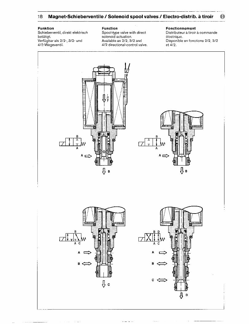
18 Magnet-Schieberventile / Solenoid spool valves/ Electro-distrib. a tiroir @
Funktion FunctionSchieberventil, direkt elektrisch
FonctionnementSpool-type valve with direct
betatigt.Distributeur a tiroira commande
solenoid actuation. electrique.Verfugbar als 212-, 312- und Available as 2/2, 3/2 and Disponibie en fonctions 2/2, 3/24/2-Wegeventil. 4/2 directional-control valve. et 4/2.
Cz
oc
@ Magnet-Schieberventile / Solenoid spool valves/ Electro-distrib. a tiroir 19
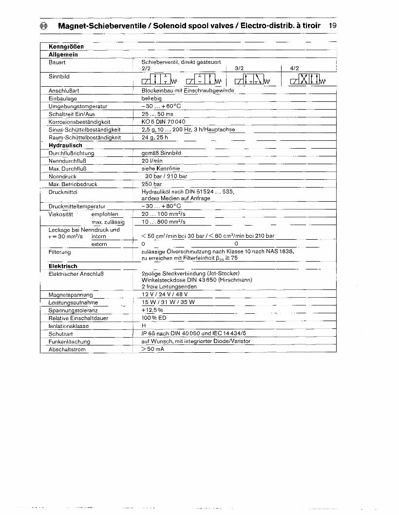
Kenngroi3en
Allgemein
Bauart Schieberventil, direkt gesteuert2/2 312 412
Sinnbiid t. [Anschlu13art Blockeinbau mit Einschraubgewinde
Einbaulage beliebig
Umgebungstemperatur –30 ... +60”C
Schaltzeit Ein/Aus 25... 5Oms
Korrosionsbestandigkeit K05 DIN 70040
Sinus-Schtittelbestandigkeit 2,5 g, 10...200 Hz, 3 h/Hauptachse
Raum-Schuttelbestandigkeit 24 g, 25 h
Hydra ulisch
Durchflu13richtung gema~ Sinnbild
Nenndurchfluf3 20 l/rein
Max. Durchflu13 siehe Kennlinie
Nenndruck 30 bar/210 bar
Max. Betriebsdruck 250 bar
Druckmittel Hydraulikol nach DIN 51524...535,
andere Medien auf Anfrage
Druckmitteltemperatur -30.., +80°C
Viskositat empfohlen 20...100 mm2/s
max. zulassig 10...800 mm2/s
Leckage bei Nenndruck undu = 30 mm2/s intern <50 cm3/min bei 30 bar/< 80 cm3/min bei 210 bar
extern o 0Filterung zulassige Olverschmutzung nach Klasse 10 nach NAS 1638,
zu erreichen mit Filterfeinheit ~z~ Z 75
Elektrisch
Elektrischer Anschluf3 2polige Steckverbindung (Jet-Stecker)Winkelsteckdose DIN 43650 (Hirschmann)2 freie Leitungsenden
Magnetspannung 12 V/24 V148V
Leistungsaufnahme 15w/31w/35w
Span nungstoleranz +12,50/o
Relative Einschaltdauer 100 O/oED
Isolationsklasse H
Schutzart IP 65 nach DIN 40050 und IEC 14434/5
Funkenloschung auf Wunsch, mit integrierter Diode/Varistor
Abschaltstrom >50 mA
20 Magnet-Schieberventile / Solenoid spool valves/ Electro-distrib. a tiroir @
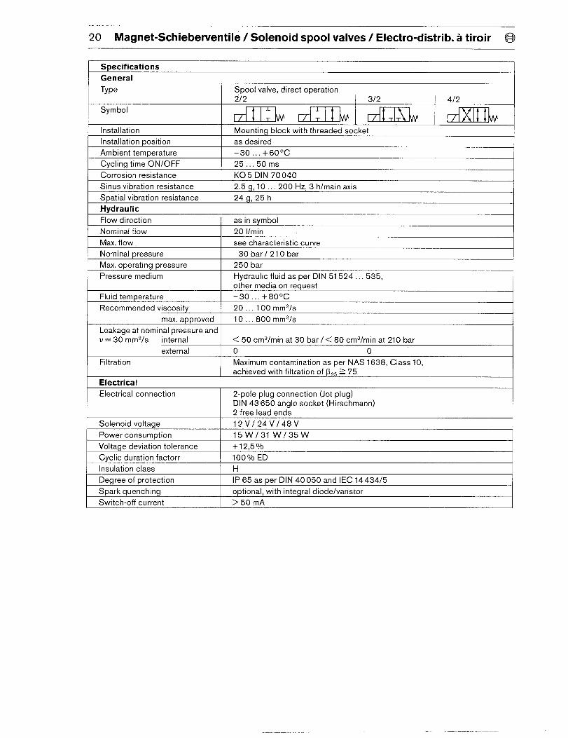
Specifications 1General
Type Spool valve, direct operation212 312 4/2
Symbol L I L tInstallation Mounting block with threaded socket
Installation position as desired
Ambient temperature –30... +6O”C
Cycling time ON/OFF 25.,. 50ms
Corrosion resistance K05 DIN 70040
Sinus vibration resistance 2.5 g, 10...200 Hz, 3 h/main axis
Spatial vibration resistance 24 g, 25 h
Hydraulic
Flow direction as in symbol
Nominal flow 20 l/rein
Max. flow see characteristic curve
Nominal pressure 30 bar/ 210 bar
Max. operating pressure 250 bar
Pressure medium Hydraulic fluid as per DIN 51524...535,
other media on request
Fluid temperature -30 . . . +80°C
Recommended viscositv 20 . . . 100 mm2/s
max. armroved 10.,.800 mm2/s
Leakage at nominal pressure and I Iv = 30-mm2/s internal <50 cm3/min at 30 bar/< 80 cm3/min at 210 bar
external o 0Filtration Maximum contamination as per NAS 1638, Class 10,
achieved with filtration of ~2~ >75
Electrical
Electrical connection 2-pole plug connection (Jet plug)DIN 43650 angle socket (Hirschmann)
2 free lead ends
Solenoid voltage 12 V124V148V
Power consum~tion 15w/31w/35w
Voltaae deviation tolerance +12.5170
Cyclic duration factorr 100 O/oED
Insulation class H
Degree of protection IP 65 as per DIN 40050 and IEC 14434/5
Spark quenching optional, with integral diode/varistor
Switch-off current >50 mA
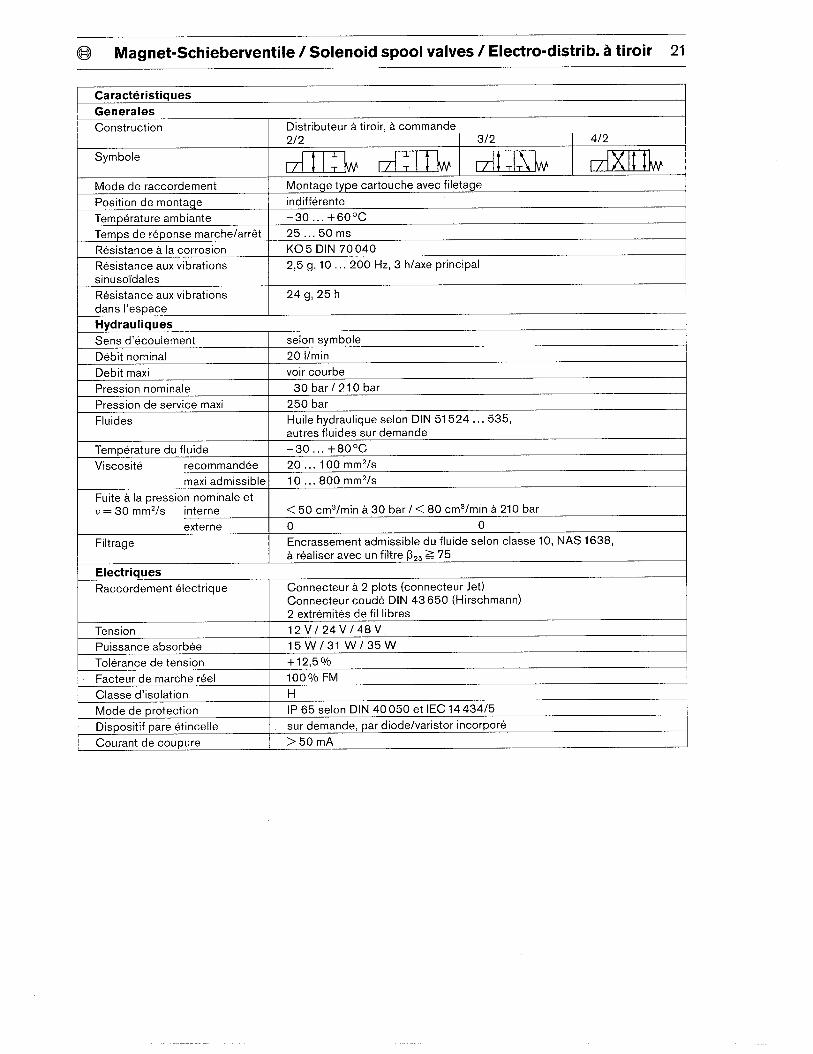
@ Magnet-Schieberventile / Solenoid spool valves/ Electro-distrib. a tiroir 21
Caracteristiques
Generales
Construction Distributeur atiroir, a commande2/2 3/2 4/2
Symbole J.T IL I t IL
Mode de raccordement Montage type cartouche avec filetage
Position de montage indifference
Temperature ambiante –30... +6O”C
Temps de reponse marche/arr& 25... 5Oms
Resistance a la corrosion K05 DIN 70040
Resistance aux vibrations 2,5 g, 10...200 Hz, 3 h/axe principal
sinuso”idales
Resistance aux vibrations 24 g, 25 h
clans I’espace
Hydrauliques
Sens d’ecoulement selon symbole
Debit nominal 20 i/rein
Debit maxi voir courbe
Pression nominale 30 bar/ 210 bar
Pression de service maxi 250 bar
Fluides Huile hydraulique selon DIN 51524...535,autres ~luides sur demande
Temperature du fluide –30... +8O”C
Viscosite recommandee 20...100 mm2/s
maxi admissible 10...800 mm2/s
Fuite a la pression nominale etV= 30 mm2/s interne <50 cm3/min a 30 bar/< 80 cm3/min a 210 bar
externe o 0Filtrage Encrassement admissible du fluide selon classe 10, NAS 1638,
a realiser avec un filtre ~2S Z 75
Electriques
Raccordement electrique Connecter a 2 plots (connecter Jet)Connecter coude DIN 43650 (Hirsch mann)2 extremities de fil Iibres
Tension 12 V124V148V
Puissance absorbee 15w/31w/35w
Tolerance de tension +12,5Yo
Facteur de marche reel 100VO FM
Classe d’isolation H
Mode de protection 1P 65 selon DIN 40050 et IEC 14434/5
Dispositif pare etincelle sur demande, par diode/varistor incorpore
Courant de coupure >50 mA
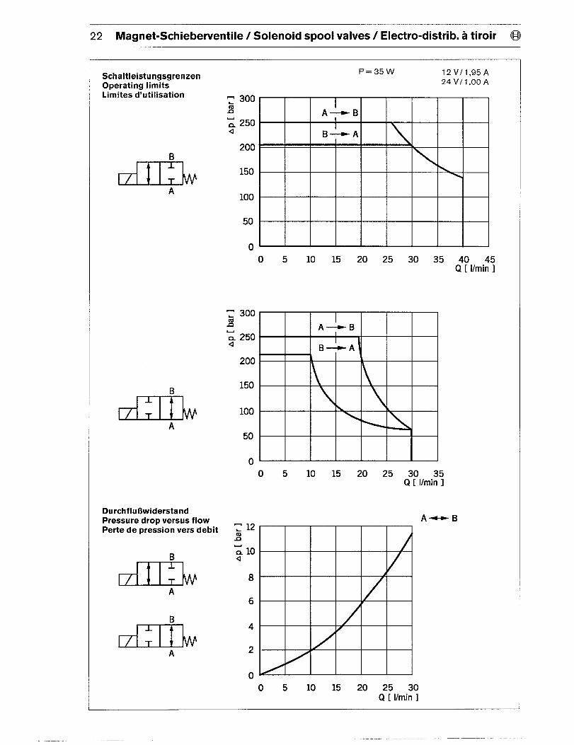
22 Magnet-Schieberventile / Solenoid spool valves/ Electro-distrib. a tiroir @
SchaltleistungsgrenzenOperating limitsLimites d’utilisation
B
A
BL
T
; 300n
200
150
100
50
0
200
150
100
A50
0
DurchfluOwiderstandPressure drop versus flowPerte de pression vers debit
B
A
B-L
T
A
P=35W 12 V11,95A
24 V/1,00A
O 5 10 15 20 25 30 35 40 45Q [ Vmin 1
O 5 10 15 20 25 30 35Q [ l/rein 1
8m
6
4
2
o~O 5 10 15 20 25 30
Q [ l/rein 1
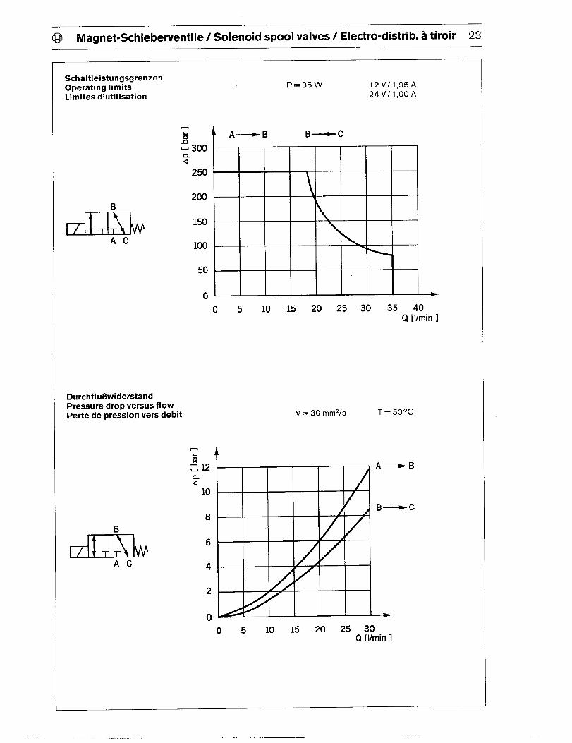
@ Magnet-Schieberventile / Solenoid SPOOIvalves/ Ele~ro-distrib~ ~ tiroir 23
SchaltleistungsgrenzenOperating limitsLimites d’utilisation
B
I TIAL
AC
, P=35W 12 V/l,95A24 V11,00A
Durchfhr6widerstandPressure drop versus flowPerte de pression vers debit
.
? 12n.4
10
8
0 5 10 15 m 25 30 35 40Q [I/rein 1
B
I
AC
6
4
2
0
v = 30 mm2/s
o 5 10 15 20 25 30Q [l/rein 1
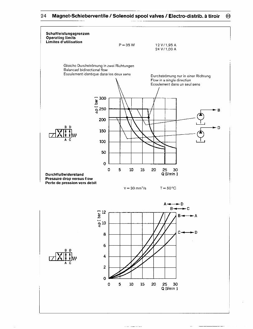
24 Magnet-Schieberventile / Solenoid spool valves/ Electro-distrib. a tiroir @
SchaltleistungsgrenzenOperating limitsLimites d’utilisation
P=35W
Gleiche Durchstromung in zwei RichtungenBalanced bidirectional flow
Ecoulement identique clans Ies deux sens
200
Durchflu BwiderstandPressure drop versus flowPerte de pression vers debit
150
100
50
0
8
6
4
AC
2
0
12 V11,95A24 V/1,00 A
Durchstromuna nur in einer Richtuna
iFlow in a singl~ direction
.
Ecoulement clans un seul sens
o 5 10 15 20 25 30Q [l/rein ]
v = 30 mm2/s T=50”C
o 5 10 15 20 25 30Q [l/rein 1
@ Magnet-Schiebet’ventile / Solenoid spool valves/ Electro-distrib. a tiroir 25
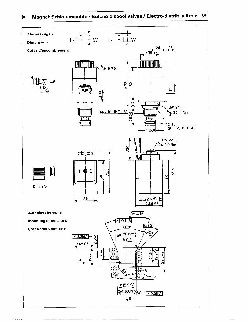
AbmessungenB B
1
DimensionsT
A
Cotes d’encombrement
_ ,’
1 527 010 343
mc >
DIN/lSO
Au fnahmebohrung
Mounting dimensions
Cotes d’implantation
)3_
1111
FomCN ILSw 22
~9+3Ntn
I
7 :
Inm-
omIn
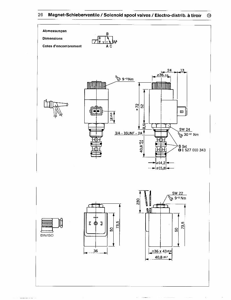
26 Magnet-Schieberventile / Solenoid spool valves/ Electro-distrib. a tiroir @
AbmessungenR
DimensionsI
Cotes d’encombrement AC
>1’
DIN/lSO
I I I
_-!-
3/4 - 16UNF - 2)
[
NIn
la
ml
J
Jai ~SW 24
~b 30’2 1Nm
;?a Q Set5t 1 527 010 343
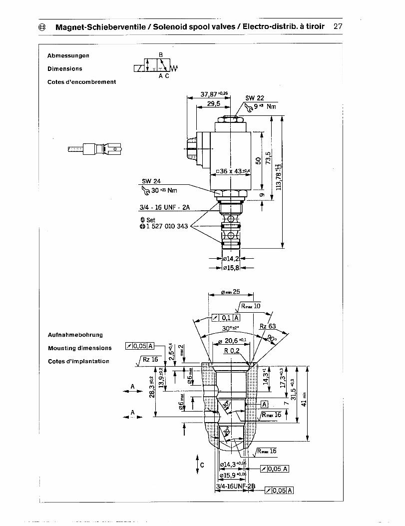
@ Magnet-Schieberventile / Solenoid spool valves/ Electro-distrib. a tiroir 27
Abmessungen
Dimensions
B
I
ACCotes d’encombrement
1 527 010 343
Au fnahmebohrung
Mounting dimensions
Cotes d’implantation
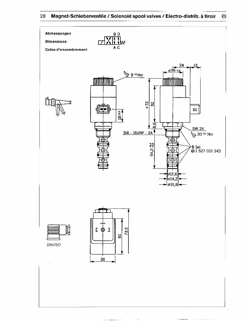
28 Magnet-Schieberventile / Solenoid spool valves/ Electro-distrib. a tiroir @
Abmessungen
Dimensions
Cotes d’encombrement
1 527 010 343
DIN/lSO
BD
Ac
I
I I
1
1 1
.—.
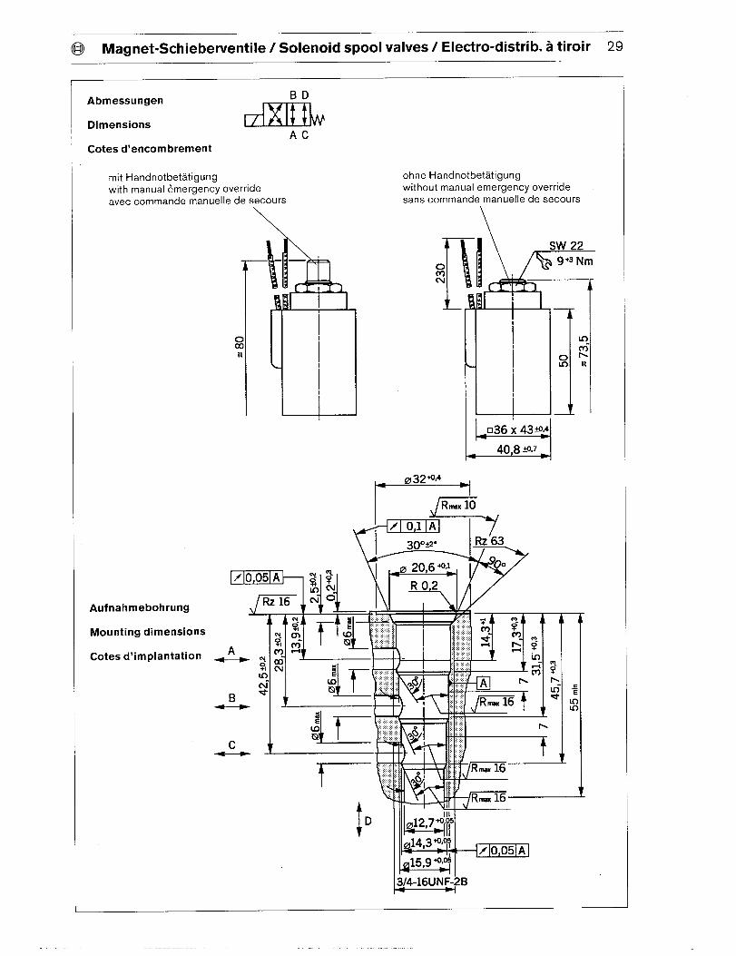
@ Magnet-Schieberventile / Solenoid spool valves/ Electro-distrib. a tiroir 29
Abmessungen BD
DimensionsAC
Cotes d’encombrement
mit Handnotbetatigungwith manual &mergency override
avec commande manuelle de secours\
Au fnahmebohrung
Mounting dimensions
Cotes d’implantation
ohne Handnotbetatigungwithout manual emergency override
saris commande manuelle de secours
tin
t-6-0;In
I
1+032+’34
-i
,,c I
\ -II?.. lK
30 Magnet-Schieberventile / Solenoid spool valves/ Electro-distrib. a tiroir @
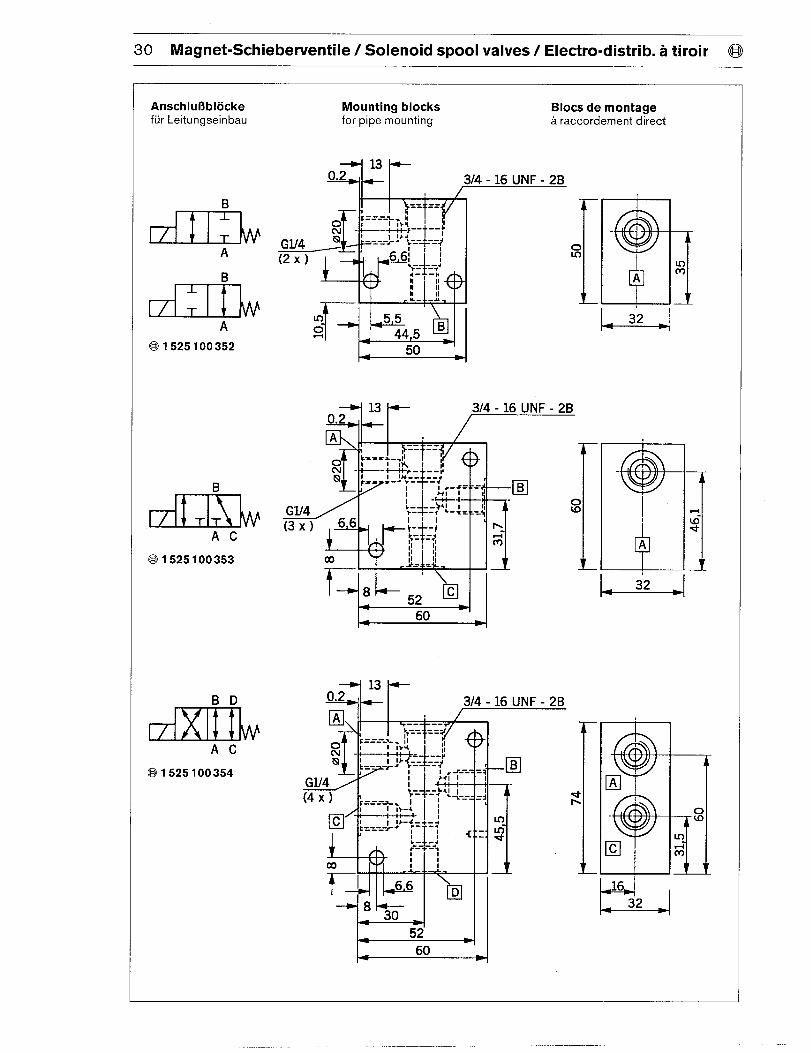
Anschlufiblocke Mounting blocks Blocs de montagefur Leitungseinbau for pipe mounting a raccordement direct
B
A
B-L
T
A
@ 1525100352
B
IA
AC
1 525 100 353
BD
AC
1 525 100 354
/3/4 -1 6 UNF -21
I I .&_ _i. I I
3/4 -1 6 UNF - 2B
ou)
1 I . A+A4. . I I 1 L
- 13 +0.2 + 314-1 6 UNF - 2B
d .--4--./ I
.- .--~1 66
D
8 30
5260

ROBERT BOSCH FLUID POWER CORPORATIONP.O. BOX 2025RACINE, WISCONSIN 53401-2025 U.S.A.Phone (414)554-7100, Fax (414)554-7117
PRINTED IN U.S.A.
9 535 233 176HPUS AKY 011/1 US (7.95)


![Dialkylresorcine aus Pseudomonas aureofaciens [1]zfn.mpdl.mpg.de/data/Reihe_B/35/ZNB-1980-35b-0909.pdf · eine Aromaten- (1638 cm-1), sowie eine breite Hydroxylbande zu erkennen,](https://img.pdfslide.org/doc/110x75/5f06ac457e708231d4192a18/dialkylresorcine-aus-pseudomonas-aureofaciens-1zfnmpdlmpgdedatareiheb35znb-1980-35b-0909pdf.jpg)