Embed Size (px)
Citation preview
Digitales Manometer mit Schaltausgängen
Digital Manometer with Switch Outputs
Manomètre Numérique à seuils
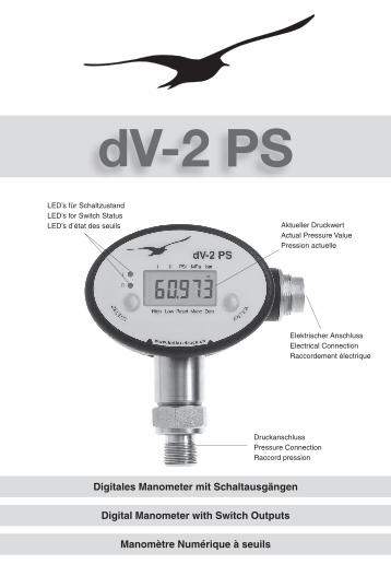
Aktueller DruckwertActual Pressure ValuePression actuelle
LED’s für SchaltzustandLED’s for Switch StatusLED’s d’état des seuils
Elektrischer AnschlussElectrical ConnectionRaccordement électrique
DruckanschlussPressure ConnectionRaccord pression
dV-2 PS
Allgemeines
Das dV-2 PS ist ein digitales Manometer mit zwei konfi-gurierbaren Schaltausgängen und einer seriellen Schnittstelle (RS485). Über die linke Taste (SELECT) werden die Funktionen sowie die Druckeinheiten angewählt. Die rechte Taste (ENTER) ak-tiviert die angewählte Funktion oder Druckeinheit. Im Display erscheinende Pfeile (^) oder (^) zeigen auf ein auf die Frontfolie aufgedrucktes Kommando, eine Einheit oder einen Hinweis.
Einschalten:
Beim Anlegen der Stromversor-gung schaltet sich das Gerät ein. Nach dem Segmenttest wird die Softwareversion (Jahr/Woche) und dann der abge-glichene Druckbereich (in bar) des Gerätes angezeigt. Danach befindet sich das Gerät im Messmodus. Das Display zeigt den aktuellen Druck, die 2 LED zeigen den Schaltzustand der Schaltausgänge (LED leuchtet, wenn Schaltausgang geschlos-sen). Ein Pfeil zeigt auf die Druckeinheit, in der das Gerät den Druck anzeigt.
Anzeigen der Schalterkonfiguration:
Über die rechte Taste kann die Schalter konfiguration abgerufen werden.
Gerätefunktionen / Einheiten
Das dV-2 PS speichert fortlau-fend den Maximalwert (High) und den Minimalwert (Low) des Druckes, der aufgetreten ist.
General
The dV-2 PS is a digital mano-meter with two configurable switch outputs and a serial inter-face (RS485).
The left key (SELECT) serves to select the functions and the pressure units. The right key (ENTER) activates the selected function or pressure unit.
Arrows (^) or (^) that appear on the display point to a command, unit or note printed on the front label.
Turn-on:
The dV-2 PS automatically turns on when connecting it to the po-wer supply. After the segments test, the instrument first displays the software version (year/month), followed by the full scale pressu-re range (in bar), before leading into the measuring mode. The display now shows the actual pressure, the 2 LED on the front indicate the switch output status (LED is on if the switch output is closed). An arrow points to the pressure unit in use.
Indication of the switch configuration:
Pressing the right key (ENTER) allows to call up the switch con-figuration.
Functions / Units The dV-2 PS continuously stores the maximal pressure (High) and the minimal pressure (Low).
Généralités
Le dV-2 PS est un manomètre numérique avec deux sorties à seuils configurables et une inter-face série (RS485).
La touche de gauche (SELECT) permet de sélectionner les fonc-tions et l’unité de pression. La touche de droite (ENTER) valide la fonction ou l’unité de mesure sélectionnée. Les flèches (^) ou (^) apparais-sant sur l’affichage désignent l’unité active, une commande ou une indication imprimée sur la face avant.
Mise en route :
L’instrument se met en marche dès que l’alimentation élec-trique est établie. Après le test d’affichage, la version du logi-ciel (année/mois) est d’abord affichée, puis l’étendue de me-sure calibrée de l’instrument (en bar).L’instrument se trouve en-suite en mode de mesure. L’affichage montre la pression actuelle. Les deux LED in-diquent l’état de commutation des sorties à seuil. Une flèche indique l’unité de pression dans laquelle l’instrument opère. Affichage de la configuration des commutateurs :
la touche de droite permet d’interroger la configuration.
Fonctions / Unités Le dV-2 PS mémorise continu-ellement les valeurs maximale (High) et minimale (Low) de la pression.
- 2 -
^^ ^
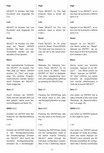
High SELECT 1x drücken: Der High Druckwert wird angezeigt (für 5 s).
Low SELECT 2x drücken: Der Low Druckwert wird angezeigt (für 5 s).
Reset SELECT 3x drücken: Ein Pfeil zeigt auf ”Reset”. ENTER drücken: Die High- und Low-Druckwerte werden auf den aktuellen Druck gesetzt.
Mano Gibt nachstehende Funktionen frei: SELECT 4x drücken. Der Pfeil zeigt auf ”Mano”. ENTER drücken: Set ”Zero” wird ange-zeigt. Die anderen Program-mierfunktionen werden danach durch Drücken der SELECT-Taste aufgerufen.
Zero SET Durch Drücken der ENTER-Taste wird der aktuelle Wert auf Null gesetzt (siehe auch Be-reiche/Abgleich auf Seite 10).
ZERO rESEt Drücken von ENTER setzt den Nullpunkt auf Werkseinstellung zurück.
S sET
Drücken der ENTER-Taste führt in den Konfigurationsmodus der Schalt ausgänge. Drücken von SELECT führt durch die einzelnen Konfigurationsmög-lichkeiten der 2 Schaltausgän-
High Press SELECT 1x: The High pressure value is shown (for 5 sec.).
Low Press SELECT 2x: The Low pressure value is shown (for 5 sec.).
Reset Press SELECT 3x: An arrow points to ”Reset”. Press ENTER: The High and Low pressure va-lues are set to the actual pres-sure.
Mano Releases the following func-tions: Press SELECT 4x. An arrow points to ”Mano”. Press ENTER: Set ”Zero” is displayed. The other programming func-tions are subsequently called up by pressing the SELECT-key.
Zero SET Pressing the ENTER-key sets the actual value to zero (also see Ranges/Calibration on page 10).
Zero resET Pressing the ENTER-key sets the zero back to the factory set-ting.
S sET
Pressing the ENTER-key leads into the configuration mode of the switch outputs. Pressing SELECT leads through the individual configuration possibi-lities of the 2 switching outputs
High Appuyer 1x sur SELECT : la va-leur maxi de la pression s’affiche (pour 5 s)
Low Appuyer 2x sur SELECT : la va-leur mini de la pression s’affiche (pour 5 s)
Reset Appuyer 3x sur SELECT : une flèche pointe sur ”Reset”. Appuyer sur ENTER : les va-leurs maxi et mini de la pression sont remises à zéro.
Mano Donne accès aux fonctions suivantes : Appuyer 4x sur SE-LECT : une flèche pointe sur ”Mano”. Appuyer sur ENTER : Set ”Zero” s’affiche. Les autres fonctions de programmation sont ensuite sélectionnées à l’aide de la touche SELECT.
Zero SET Une action sur ENTER met la valeur actuelle à zéro (voir aussi ”Etendues de Mesure/Calibra-tion” à la page 10).
ZERO resET Une action sur ENTER restaure le zéro réglé en usine.
S sET
Une action sur ENTER permet de passer en mode de configu-ration des seuils. Appuyer sur SELECT pour parvenir aux dif-férentes possibilités de configu-ration des 2 Sorties commutées
- 3 -
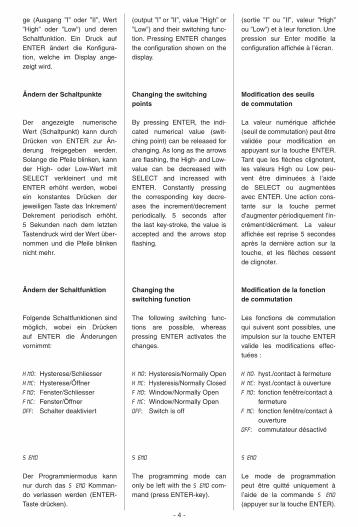
ge (Ausgang ”I” oder ”II”, Wert ”High” oder ”Low”) und deren Schaltfunktion. Ein Druck auf ENTER ändert die Konfigura- tion, welche im Display ange-zeigt wird.
Ändern der Schaltpunkte
Der angezeigte numerische Wert (Schaltpunkt) kann durch Drücken von ENTER zur Än-derung freigegeben werden. Solange die Pfeile blinken, kann der High- oder Low-Wert mit SELECT verkleinert und mit ENTER erhöht werden, wobei ein konstantes Drücken der jeweiligen Taste das Inkrement/Dekrement periodisch erhöht. 5 Sekunden nach dem letzten Tastendruck wird der Wert über-nommen und die Pfeile blinken nicht mehr.
Ändern der Schaltfunktion
Folgende Schaltfunktionen sind möglich, wobei ein Drücken auf ENTER die Änderungen vornimmt:
H nO: Hysterese/SchliesserH NC: Hysterese/Öffner F NO: Fenster/Schliesser F NC: Fenster/Öffner OFF: Schalter deaktiviert
S end
Der Programmiermodus kann nur durch das S end Komman-do verlassen werden (ENTER-Taste drücken).
(output ”I” or ”II”, value ”High” or ”Low”) and their switching func-tion. Pressing ENTER changes the configuration shown on the display.
Changing the switching points
By pressing ENTER, the indi-cated numerical value (swit-ching point) can be released for changing. As long as the arrows are flashing, the High- and Low-value can be decreased with SELECT and increased with ENTER. Constantly pressing the corresponding key decre-ases the increment/decrement periodically. 5 seconds after the last key-stroke, the value is accepted and the arrows stop flashing.
Changing the switching function
The following switching func-tions are possible, whereas pressing ENTER activates the changes.
H NO: Hysteresis/Normally OpenH NC: Hysteresis/Normally ClosedF NO: Window/Normally Open F NC: Window/Normally Open OFF: Switch is off
S end
The programming mode can only be left with the S end com-mand (press ENTER-key).
(sortie ”I” ou ”II”, valeur ”High” ou ”Low”) et à leur fonction. Une pression sur Enter modifie la configuration affichée à l’écran.
Modification des seuils de commutation
La valeur numérique affichée (seuil de commutation) peut être validée pour modification en appuyant sur la touche ENTER. Tant que les flèches clignotent, les valeurs High ou Low peu-vent être diminuées à l’aide de SELECT ou augmentées avec ENTER. Une action cons-tante sur la touche permet d’augmenter périodiquement l’in-crément/décrément. La valeur affichée est reprise 5 secondes après la dernière action sur la touche, et les flèches cessent de clignoter.
Modification de la fonction de commutation
Les fonctions de commutation qui suivent sont possibles, une impulsion sur la touche ENTER valide les modifications effec-tuées :
H NO: hyst./contact à fermeture H NC: hyst./contact à ouverture F NO: fonction fenêtre/contact à fermeture F NC: fonction fenêtre/contact à ouverture OFF: commutateur désactivé
S end
Le mode de programmation peut être quitté uniquement à l’aide de la commande S end (appuyer sur la touche ENTER).
- 4 -
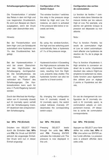
Schaltausgangskonfiguration
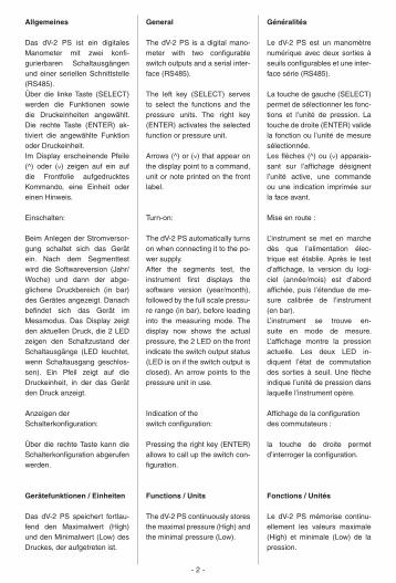
Die Fensterfunktion F schaltet das Relais in dem mit High und Low begrenzten Druck bereich. Es wird zum Beispiel ein Alarm ausgegeben, wenn der Druck unter- oder überschritten wird.
Hinweis:
Bei der Fensterfunktion wird beim High- und Low-Schaltpunkt automatisch eine Hysterese von 1‰ des Druckbereiches fest-gelegt.
Bei der Hysteresefunktion H wird bei einem Überschrei-ten des High-Druckes der Schaltausgang durchgeschal-tet. Die Schalthysterese, die sich aus High/Low ergibt, verhindert ein “Flattern” des Schaltausganges. Die Hys-teresefunktion kann auch für eine 2 Punkt-Regelung be nutzt werden.
Durch den Wechsel der Konfigu-ration von NC (normally closed) auf NO (normally open) verhält sich der Schaltausgang invers. OFF deaktiviert den ent sprechen-den Schaltausgang.
bar MPa PSI (Einheit) Drücken von SELECT führt durch die Einheiten bar, MPa und PSI. Ein Druck auf ENTER aktiviert die angezeigte Einheit. Der Druck wird nun in dieser Einheit angezeigt.
Configuration of the Switch Output
The window function F switches the relay in the pressure range limited by High and Low. For instance, an alarm is activated if the pressure falls below or ex-ceeds set limits.
Note:
By using the window-function, the high and low switching point automatically fixes a hysteresis of 1 ‰ of the pressure range.
Hysteresis function H: Exceeding the High-pressure activates the switch output. The switch hyste-resis, resulting from the High/Low, prevents relay chatter. The hysteresis function can also be used for a 2-level-control.
By changing the configuration from NC (normally closed) to NO (normally open), the switch output behaves inversely. OFF deactivates the corresponding switch output.
bar MPa PSI (Unit) Pressing SELECT leads through the units bar, MPa and PSI. Pressing ENTER activates the indicated unit. The pressure is now displayed in this unit.
Configuration des sorties de commutation
La fonction de fenêtre F com-mute le relais dans l’étendue de mesure limitée par les valeurs High et Low. Par exemple, une alarme est générée lorsque la pression est dépassée ou non atteinte.
Nota :
Pour la fonction Fenêtre, les seuils de commutation High et Low se voient automatique-ment affecter une hystérésis de réaction de 1‰ de la plage de mesure.
Pour la fonction d’hystérésis H, High entraîne la connexion en direct de la sortie. L’hystérésis résultant des valeurs High/Low empêche le battement du relais. Cette fonction peut également être utilisée pour un réglage 2 points si l’hystérésis est éle-vée.
En cas de changement de con- figuration de NC (normally clo-sed) à NO (normally open), la commutation adopte un com-portement inverse. OFF désac-tive la sortie de commutation correspondante.
bar MPa PSI (Unité) Appuyer sur SELECT pour faire défiler les unités bar, MPa et PSI. Une action sur ENTER ac-tive l’unité affichée. La pression sera à présent affichée dans cette unité.
- 5 -
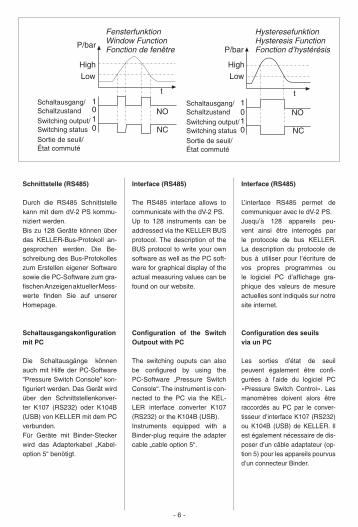
Interface (RS485)
L’interface RS485 permet de communiquer avec le dV-2 PS. Jusqu’à 128 appareils peu-vent ainsi être interrogés par le protocole de bus KELLER. La description du protocole de bus à utiliser pour l’écriture de vos propres programmes ou le logiciel PC d’affichage gra-phique des valeurs de mesure actuelles sont indiqués sur notre site internet.
Configuration des seuils via un PC
Les sorties d’état de seuil peuvent également être confi-gurées à l’aide du logiciel PC «Pressure Switch Control». Les manomètres doivent alors être raccordés au PC par le conver-tisseur d’interface K107 (RS232) ou K104B (USB) de KELLER. Il est également nécessaire de dis-poser d’un câble adaptateur (op-tion 5) pour les appareils pourvus d’un connecteur Binder.
Interface (RS485)
The RS485 interface allows to communicate with the dV-2 PS.Up to 128 instruments can be addressed via the KELLER BUS protocol. The description of the BUS protocol to write your own software as well as the PC soft-ware for graphical display of the actual measuring values can be found on our website.
Configuration of the Switch Outpout with PC
The switching ouputs can also be configured by using the PC-Software „Pressure Switch Console“. The instrument is con-nected to the PC via the KEL-LER interface converter K107 (RS232) or the K104B (USB).Instruments equipped with a Binder-plug require the adapter cable „cable option 5“.
Schnittstelle (RS485)
Durch die RS485 Schnittstelle kann mit dem dV-2 PS kommu-niziert werden.Bis zu 128 Geräte können über das KELLER-Bus-Protokoll an-gesprochen werden. Die Be-schreibung des Bus-Protokolles zum Erstellen eigener Software sowie die PC-Software zum gra-fischen Anzeigen aktueller Mess- werte finden Sie auf unserer Homepage.
Schaltausgangskonfiguration mit PC
Die Schaltausgänge können auch mit Hilfe der PC-Software ”Pressure Switch Console” kon-figuriert werden. Das Gerät wird über den Schnittstellenkonver-ter K107 (RS232) oder K104B (USB) von KELLER mit dem PC verbunden.Für Geräte mit Binder-Stecker wird das Adapterkabel „Kabel-option 5“ benötigt.
- 6 -
P/barP/bar
High
NO
NCNC
tt1
010
0101
Low
High
Low
NO
FensterfunktionWindow FunctionFonction de fenêtre
HysteresefunktionHysteresis FunctionFonction d’hystérésis
Schaltausgang/SchaltzustandSwitching output/Switching statusSortie de seuil/État commuté
Schaltausgang/SchaltzustandSwitching output/Switching statusSortie de seuil/État commuté
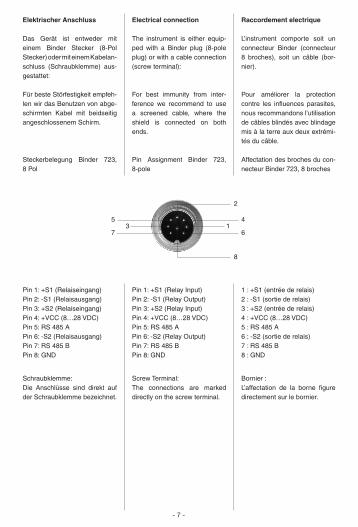
Elektrischer Anschluss
Das Gerät ist entweder mit einem Binder Stecker (8-Pol Stecker) oder mit einem Kabelan- schluss (Schraubklemme) aus-gestattet:
Für beste Störfestigkeit empfeh-len wir das Benutzen von abge-schirmten Kabel mit beidseitig angeschlossenem Schirm.
Steckerbelegung Binder 723, 8 Pol
Pin 1: +S1 (Relaiseingang)Pin 2: -S1 (Relaisausgang)Pin 3: +S2 (Relaiseingang)Pin 4: +VCC (8…28 VDC) Pin 5: RS 485 APin 6: -S2 (Relaisausgang)Pin 7: RS 485 BPin 8: GND
Schraubklemme:Die Anschlüsse sind direkt auf der Schraubklemme bezeichnet.
Electrical connection
The instrument is either equip-ped with a Binder plug (8-pole plug) or with a cable connection (screw terminal):
For best immunity from inter-ference we recommend to use a screened cable, where the shield is connected on both ends.
Pin Assignment Binder 723, 8-pole
Pin 1: +S1 (Relay Input) Pin 2: -S1 (Relay Output) Pin 3: +S2 (Relay Input) Pin 4: +VCC (8…28 VDC) Pin 5: RS 485 APin 6: -S2 (Relay Output)Pin 7: RS 485 BPin 8: GND
Screw Terminal:The connections are marked directly on the screw terminal.
Raccordement electrique
L’instrument comporte soit un connecteur Binder (connecteur 8 broches), soit un câble (bor-nier).
Pour améliorer la protection contre les influences parasites, nous recommandons l’utilisation de câbles blindés avec blindage mis à la terre aux deux extrémi-tés du câble.
Affectation des broches du con-necteur Binder 723, 8 broches
1 : +S1 (entrée de relais) 2 : -S1 (sortie de relais) 3 : +S2 (entrée de relais) 4 : +VCC (8…28 VDC)5 : RS 485 A6 : -S2 (sortie de relais)7 : RS 485 B8 : GND
Bornier :L’affectation de la borne figure directement sur le bornier.
- 7 -
7 613
45
2
8
Sortie de commutation (configuration)
L’entrée de relais (+) de chaque commutateur peut être connec-tée en permanence au +VCC (le relais commute à la charge reliée au GND) via le commuta-teur rotatif ou au GND (le relais commute à la charge reliée au +VCC).
Position de commutateur 1 : Entrée du relais connectée au +VCC
Position de commutateur 2 :L’entrée du relais est connectée en direct (fonction normale de relais)
Position de commutateur 3 :Entrée du relais connectée au GND
Le seuil de commutation ne doit être réglé qu’en l’absence de toute tension appliquée au cir-cuit commuté.
Charge de coupure max. du re-lais : 28 V / 0,4 A.
Switch Output (Configuration)
Via the turn-switch, the (+) relay input of each switch can perma-nently be connected to +VCC (relay switches load, which is connected with GND) or to GND (relay switches load, which is connected with +VCC).
Switch position 1: Relay input is connected with +VCC
Switch position 2:Relay input is activated (normal relay function)
Switch position 3:Relay input is connected with GND
The switch position should only be changed if the instrument is disconnected from the power supply.
Maximum switching load of the relay: 28 V / 0,4 A.
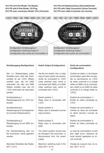
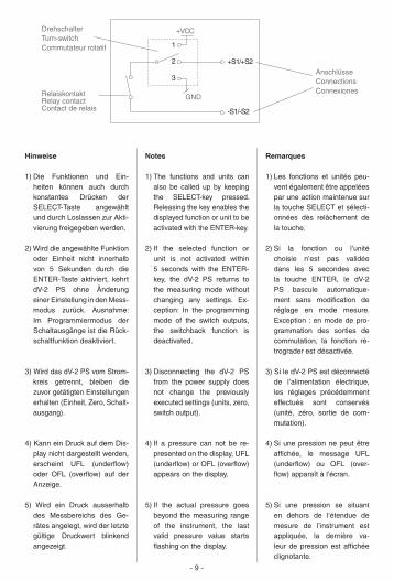
Schaltausgang (Konfiguration)
Der (+) Relaiseingang jedes Schalters kann über den Dreh-schalter fix auf +VCC (Relais schaltet Last, die mit GND verbunden ist) oder auf GND (Relais schaltet Last, die mit +VCC verbunden ist) verbunden werden.
Schalterstellung 1: Relaiseingang ist mit +VCC ver-bunden
Schalterstellung 2:Relaiseingang ist durchgeschal-tet (normale Relaisfunktion)
Schalterstellung 3:Relaiseingang ist mit GND ver-bunden
Die Schalterstellung darf nur bei stromlosen Gerät geändert werden.
Maximale Schaltlast des Relais: 28 V / 0,4 A.
- 8 -
Konfiguration Schaltausgang IIConfiguration Switching Output IIConfiguration des sorties de commutation II
Konfiguration Schaltausgang IConfiguration Switching Output IConfiguration des sorties de commutation I
RSBRSA GND -S2-S2 +S2+S2 -S1-S1 +S1+S1 RSB RSA GND +VCC+VCC
dV-2 PS mit 8 Pol Binder 723 SteckerdV-2 PS with 8 Pole Binder 723 PlugdV-2 PS avec connecteur Binder 723 à 8 broches
dV-2 PS mit Kabelanschluss (Schraubklemme)dV-2 PS with Cable Connection (Screw Terminal)dV-2 PS avec câble à brancher (sur bornier)
- 9 -
Remarques
1) Les fonctions et unités peu-vent également être appelées par une action maintenue sur la touche SELECT et sélecti-onnées dès relâchement de la touche.
2) Si la fonction ou l’unité choisie n’est pas validée dans les 5 secondes avec la touche ENTER, le dV-2 PS bascule automatique-ment sans modification de réglage en mode mesure. Exception : en mode de pro-grammation des sorties de commutation, la fonction ré-trograder est désactivée.
3) Si le dV-2 PS est déconnecté de l’alimentation électrique, les réglages précédemment effectués sont conservés (unité, zéro, sortie de com-mutation).
4) Si une pression ne peut être affichée, le message UFL (underflow) ou OFL (over-flow) apparaît à l’écran.
5) Si une pression se situant en dehors de l’étendue de mesure de l’instrument est appliquée, la dernière va-leur de pression est affichée clignotante.
Notes
1) The functions and units can also be called up by keeping the SELECT-key pressed. Releasing the key enables the displayed function or unit to be activated with the ENTER-key.
2) If the selected function or unit is not activated within 5 seconds with the ENTER-key, the dV-2 PS returns to the measuring mode without changing any settings. Ex-ception: In the programming mode of the switch outputs, the switchback function is deactivated.
3) Disconnecting the dV-2 PS from the power supply does not change the previously executed settings (units, zero, switch output).
4) If a pressure can not be re-presented on the display, UFL (underflow) or OFL (overflow) appears on the display.
5) If the actual pressure goes beyond the measuring range of the instrument, the last valid pressure value starts flashing on the display.
Hinweise
1) Die Funktionen und Ein-heiten können auch durch konstantes Drücken der SELECT-Taste angewählt und durch Loslassen zur Akti-vierung freigegeben werden.
2) Wird die angewählte Funktion oder Einheit nicht innerhalb von 5 Sekunden durch die ENTER-Taste aktiviert, kehrt dV-2 PS ohne Änderung einer Einstellung in den Mess-modus zurück. Ausnahme: Im Programmiermodus der Schaltausgänge ist die Rück-schaltfunktion deaktiviert.
3) Wird das dV-2 PS vom Strom-kreis getrennt, bleiben die zuvor getätigten Einstellungen erhalten (Einheit, Zero, Schalt-ausgang).
4) Kann ein Druck auf dem Dis-play nicht dargestellt werden, erscheint UFL (underflow) oder OFL (overflow) auf der Anzeige.
5) Wird ein Druck ausserhalb des Messbereichs des Ge-rätes angelegt, wird der letzte gültige Druckwert blinkend angezeigt.
+VCC
1
2
3
+S1/+S2
-S1/-S2
DrehschalterTurn-switchCommutateur rotatif
GNDRelaiskontaktRelay contactContact de relais
AnschlüsseConnectionsConnexiones
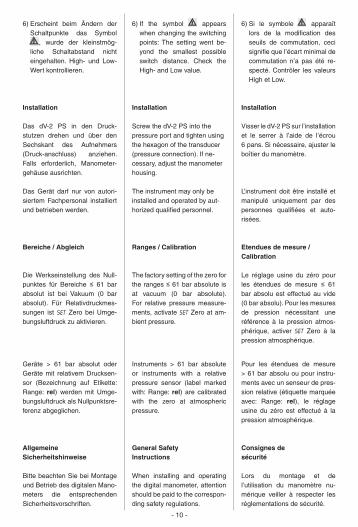
6) Erscheint beim Ändern der Schaltpunkte das Symbol
, wurde der kleinstmög-liche Schaltabstand nicht eingehalten. High- und Low-Wert kontrollieren.
Installation
Das dV-2 PS in den Druck-stutzen drehen und über den Sechskant des Aufnehmers (Druck-anschluss) anziehen. Falls erforderlich, Manometer-gehäuse ausrichten.
Das Gerät darf nur von autori-siertem Fachpersonal installiert und betrieben werden.
Bereiche / Abgleich
Die Werkseinstellung des Null- punktes für Bereiche ≤ 61 bar absolut ist bei Vakuum (0 bar absolut). Für Relativdruckmes-sungen ist SET Zero bei Umge-bungsluftdruck zu aktivieren.
Geräte > 61 bar absolut oder Geräte mit relativem Drucksen-sor (Bezeichnung auf Etikette: Range: rel) werden mit Umge-bungsluftdruck als Nullpunktsre-ferenz abgeglichen.
Allgemeine Sicherheitshinweise
Bitte beachten Sie bei Montage und Betrieb des digitalen Mano-meters die entsprechenden Sicher heitsvorschriften.
6) If the symbol appears when changing the switching points: The setting went be-yond the smallest possible switch distance. Check the High- and Low value.
Installation
Screw the dV-2 PS into the pressure port and tighten using the hexagon of the transducer (pressure connection). If ne-cessary, adjust the manometer housing. The instrument may only be installed and operated by aut-horized qualified personnel.
Ranges / Calibration
The factory setting of the zero for the ranges ≤ 61 bar absolute is at vacuum (0 bar absolute). For relative pressure measure-ments, activate SET Zero at am-bient pressure.
Instruments > 61 bar absolute or instruments with a relative pressure sensor (label marked with: Range: rel) are calibrated with the zero at atmospheric pressure.
General Safety Instructions
When installing and operating the digital manometer, attention should be paid to the correspon-ding safety regulations.
6) Si le symbole apparaît lors de la modification des seuils de commutation, ceci signifie que l’écart minimal de commutation n’a pas été re-specté. Contrôler les valeurs High et Low.
Installation
Visser le dV-2 PS sur l’installation et le serrer à l’aide de l’écrou 6 pans. Si nécessaire, ajuster le boîtier du manomètre.
L’instrument doit être installé et manipulé uniquement par des personnes qualifiées et auto-risées.
Etendues de mesure / Calibration
Le réglage usine du zéro pour les étendues de mesure ≤ 61 bar absolu est effectué au vide (0 bar absolu). Pour les mesures de pression nécessitant une référence à la pression atmos-phérique, activer SET Zero à la pression atmosphérique.
Pour les étendues de mesure > 61 bar absolu ou pour instru-ments avec un senseur de pres-sion relative (étiquette marquée avec: Range: rel), le réglage usine du zéro est effectué à la pression atmosphérique.
Consignes desécurité
Lors du montage et de l’utilisation du manomètre nu-mérique veiller à respecter les réglementations de sécurité.
- 10 -
Montieren Sie das digitale Mano-meter nur an Systeme, welche sich in drucklosem Zustand befinden.
Bei Druckbereichen ≥ 61 bar können die Druckanschlüsse pro duktions bedingt Rest mengen an Hydrauli köl aufweisen.
Bitte beachten Sie auch das zugehörige Datenblatt.
Bei Temperaturen ausserhalb 0…60 °C kann die Lesbarkeit des Displays beeinträchtigt werden.
Only mount the digital mano-meter onto unpressurized sy-stems.
On pressure ranges ≥ 61 bar, the pressure connections could show residual hydraulic oil.
Please also note the correspon-ding data sheet.
Temperatures outside of 0…60 °C could impair the readability of the display.
L’installation du manomètre nu-mérique doit être effectuée sur des systèmes hors pression.
Pour des pressions ≥ 61 bar, le raccord pression peut présenter des traces d’huile hydraulique d’étalonnage.
Veuillez également consulter la fiche technique du manomètre.
La lisibilité de l’affichage peut être affectée pour toute tem-pérature en dehors de la plage 0…60 °C.
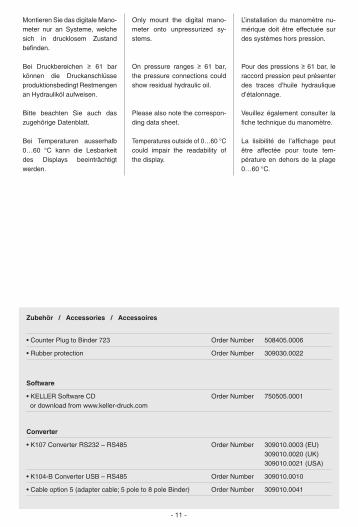
Zubehör / Accessories / Accessoires
• Counter Plug to Binder 723 Order Number 508405.0006
• Rubber protection Order Number 309030.0022
Software
• KELLER Software CD Order Number 750505.0001 or download from www.keller-druck.com
Converter
• K107 Converter RS232 – RS485 Order Number 309010.0003 (EU) 309010.0020 (UK) 309010.0021 (USA)
• K104-B Converter USB – RS485 Order Number 309010.0010
• Cable option 5 (adapter cable; 5 pole to 8 pole Binder) Order Number 309010.0041
- 11 -
KELLER AG St. Gallerstrasse 119 CH-8404 Winterthur Tel. 052 235 25 25 Fax 052 235 25 00KELLER GmbH Schwarzwaldstrasse 17 D-79798 Jestetten Tel. 07745 9214 0 Fax 07745 9214 50
www.keller-druck.com 01/2010
Konformitätserklärung
Für das folgenden Erzeugnis…
Digitales Manometer dV-2 PS
wird hiermit bestätigt, dass es den wesentlichen Schutzan-forderungen entspricht, die in der Richtlinie des Rates zur Angleichung der Rechtsvor-schriften der Mitgliedstaaten über die elektromagnetische Verträglichkeit (2004/108/EG) festgelegt ist.
Diese Erklärung gilt für alle Exemplare, die mit dem CE-Zei-chen versehen und die Bestand-teil dieser Erklärung sind.
Zur Beurteilung der Erzeugnisse hinsichtlich elektromagnetischer Verträglichkeit wurden folgende Normen herangezogen.
Diese Erklärung wird verant-wortlich für den Hersteller:
abgegeben durch die
Declaration of Conformity
Herewith we declare, that the following product…
Digital Manometer dV-2 PS
meet the basic requirements for the electromagnetic compatibility, which are established in the direc-tive of the European Community (2004/108/EC).
This declaration is valid for all ex-amples, marked with the CE sign, and which are produced according to this drawing.
As criteria for the electromagnetic compatibility, the following norms are applied:
This declaration is given for the manufacturer:
in full responsibility by
Déclaration de Conformité
Nous attestons que le produit…
Manomètre numérique dV-2 PS
répond aux exigences de base en matière de compatibilité électro-magnétique prévues par la direc-tive de la Communauté Européen-ne (2004/108/CE).
La présente déclaration est va- lable pour tout exemplaire revêtu du sigle CE faisant partie intégrante de la présente déclaration.
Les normes appliquées pour éva-luer la compatibilité électromagné-tique desdits instruments sont les suivantes :
La présente déclaration est four-nie pour le fabricant :
par :
KELLER AG für Druckmesstechnik, St. Gallerstrasse 119, CH-8404 Winterthur
KELLER GmbH, Schwarzwaldstrasse 17, D-79798 Jestetten
EN 61326-2-3:2006 EN 61000-6-3:2007 EN 61000-6-4:2007
Jestetten, 13. Januar | January | janvier 2010
Hannes W. KellerGeschäftsführender Inhaber | Managing Owner | Président Directeur Généralmit rechtsgültiger Unterschrift | with legally effective signature | dûment autorisé à signer