Embed Size (px)
Citation preview
Cremer HIP Innovations GmbH
Auf dem Flabig 6
52355 Düren (Konzendorf) – Germany
Geschäftsführer | MD: Dipl.-Ing. Marc Knauff
Tel.: +49 (0) 2421 96830 0
Fax: +49 (0) 2421 63735
Email: [email protected]
Web: www.cremer-hip-innovations.com
USt.Id.Nr. | VAT ID No.: DE318037274
St.Nr. | Tax ID No.: 207/5705/2232
HRB-Nr. | HRB No.: 7770 AG Düren
Volksbank Düren eG
IBAN: DE73 3956 0201 1009 9800 12
BIC: GENO DED1 DUE
HIP System ISOSTAR 1/4
Hot Isostatic Press
System HIP - ISOSTAR
1 Overview HIP Technology
During Hot Isostatic Pressing (HIP), the material to be
processed is heated up in special plants (HIP plants)
under argon atmosphere and high gas pressure from all
sides and under high temperatures exceeding its yield
point so compact it. For most materials, process
pressure is approx. 1000bar = 100MPa and tempera-
tures are up to 1400°C.
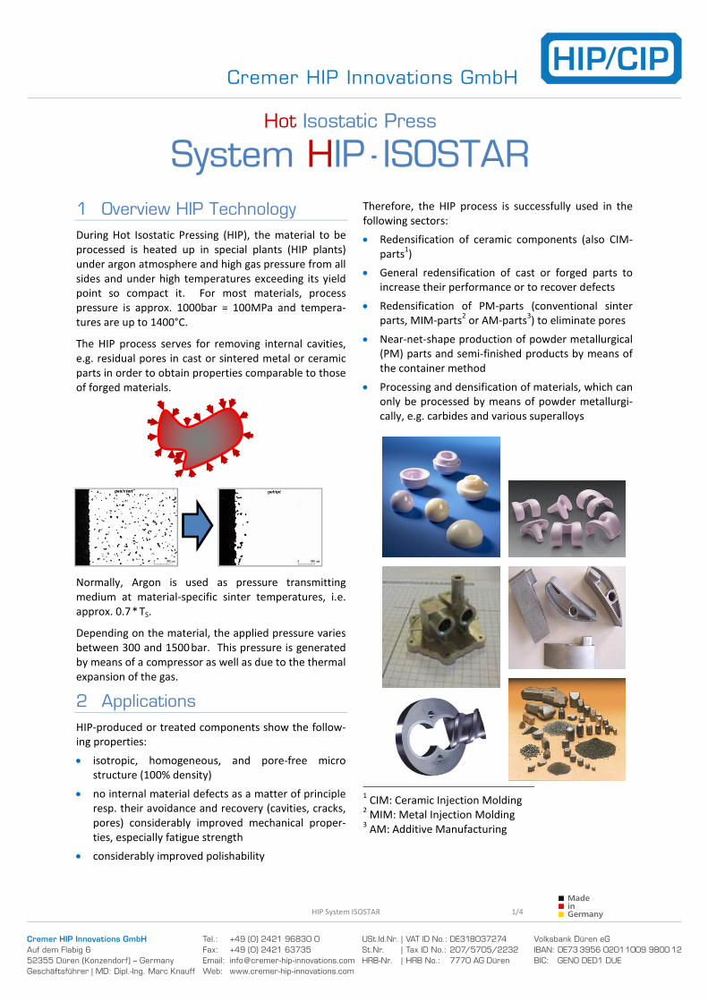
The HIP process serves for removing internal cavities,
e.g. residual pores in cast or sintered metal or ceramic
parts in order to obtain properties comparable to those
of forged materials.
Normally, Argon is used as pressure transmitting
medium at material-specific sinter temperatures, i.e.
approx. 0.7 * TS.
Depending on the material, the applied pressure varies
between 300 and 1500 bar. This pressure is generated
by means of a compressor as well as due to the thermal
expansion of the gas.
2 Applications
HIP-produced or treated components show the follow-
ing properties:
• isotropic, homogeneous, and pore-free micro
structure (100% density)
• no internal material defects as a matter of principle
resp. their avoidance and recovery (cavities, cracks,
pores) considerably improved mechanical proper-
ties, especially fatigue strength
• considerably improved polishability
Therefore, the HIP process is successfully used in the
following sectors:
• Redensification of ceramic components (also CIM-
parts1)
• General redensification of cast or forged parts to
increase their performance or to recover defects
• Redensification of PM-parts (conventional sinter
parts, MIM-parts2 or AM-parts
3) to eliminate pores
• Near-net-shape production of powder metallurgical
(PM) parts and semi-finished products by means of
the container method
• Processing and densification of materials, which can
only be processed by means of powder metallurgi-
cally, e.g. carbides and various superalloys
1 CIM: Ceramic Injection Molding
2 MIM: Metal Injection Molding
3 AM: Additive Manufacturing
Cremer HIP Innovations GmbH
Auf dem Flabig 6
52355 Düren (Konzendorf) – Germany
Geschäftsführer | MD: Dipl.-Ing. Marc Knauff
Tel.: +49 (0) 2421 96830 0
Fax: +49 (0) 2421 63735
Email: [email protected]
Web: www.cremer-hip-innovations.com
USt.Id.Nr. | VAT ID No.: DE318037274
St.Nr. | Tax ID No.: 207/5705/2232
HRB-Nr. | HRB No.: 7770 AG Düren
Volksbank Düren eG
IBAN: DE73 3956 0201 1009 9800 12
BIC: GENO DED1 DUE
HIP System ISOSTAR 2/4
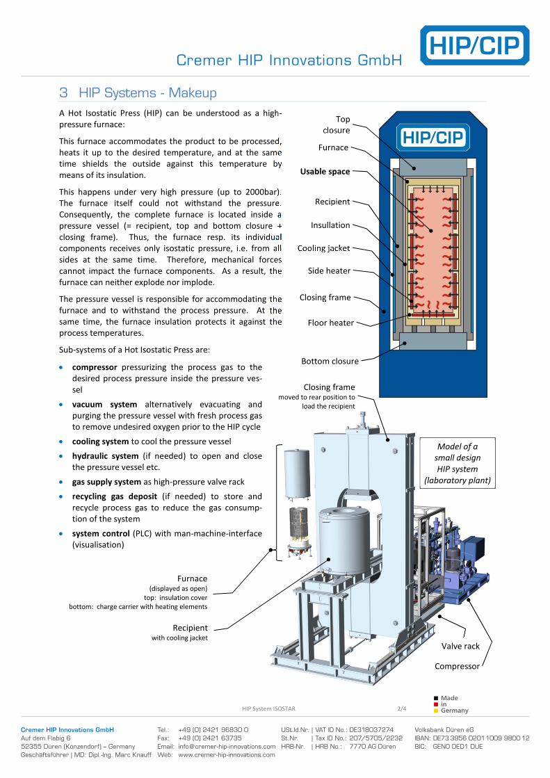
Furnace(displayed as open)
top: insulation cover
bottom: charge carrier with heating elements
Model of a
small design
HIP system
(laboratory plant)
Closing framemoved to rear position to
load the recipient
Recipientwith cooling jacket
Compressor
Valve rack
3 HIP Systems - Makeup
A Hot Isostatic Press (HIP) can be understood as a high-
pressure furnace:
This furnace accommodates the product to be processed,
heats it up to the desired temperature, and at the same
time shields the outside against this temperature by
means of its insulation.
This happens under very high pressure (up to 2000bar).
The furnace itself could not withstand the pressure.
Consequently, the complete furnace is located inside a
pressure vessel (= recipient, top and bottom closure +
closing frame). Thus, the furnace resp. its individual
components receives only isostatic pressure, i.e. from all
sides at the same time. Therefore, mechanical forces
cannot impact the furnace components. As a result, the
furnace can neither explode nor implode.
The pressure vessel is responsible for accommodating the
furnace and to withstand the process pressure. At the
same time, the furnace insulation protects it against the
process temperatures.
Sub-systems of a Hot Isostatic Press are:
• compressor pressurizing the process gas to the
desired process pressure inside the pressure ves-
sel
• vacuum system alternatively evacuating and
purging the pressure vessel with fresh process gas
to remove undesired oxygen prior to the HIP cycle
• cooling system to cool the pressure vessel
• hydraulic system (if needed) to open and close
the pressure vessel etc.
• gas supply system as high-pressure valve rack
• recycling gas deposit (if needed) to store and
recycle process gas to reduce the gas consump-
tion of the system
• system control (PLC) with man-machine-interface
(visualisation)
Closing frame
Recipient
Cooling jacket
Top
closure
Bottom closure
Side heater
Floor heater
Insullation
Usable space
Furnace
Cremer HIP Innovations GmbH
Auf dem Flabig 6
52355 Düren (Konzendorf) – Germany
Geschäftsführer | MD: Dipl.-Ing. Marc Knauff
Tel.: +49 (0) 2421 96830 0
Fax: +49 (0) 2421 63735
Email: [email protected]
Web: www.cremer-hip-innovations.com
USt.Id.Nr. | VAT ID No.: DE318037274
St.Nr. | Tax ID No.: 207/5705/2232
HRB-Nr. | HRB No.: 7770 AG Düren
Volksbank Düren eG
IBAN: DE73 3956 0201 1009 9800 12
BIC: GENO DED1 DUE
HIP System ISOSTAR 3/4
4 Furnace Types
The ISOSTAR HIP System can be furnished with various
furnace types, which are distinguishable by their
individual properties.
Graphite Furnace G200
The graphite furnace attains highest temperatures up
to 2000 °C. It is used e.g. to process ceramics or
tungsten.
Its CFC and Isographite design make it robust and
allow varied applications.
Due to the material, carbon dissolutes in the process
gas. Therefore, processing sensitive materials (e.g.
stainless steel) is possible under certain precautions.
Nevertheless, we recommend laboratory operation
only.
Molybdenum Furnace M140
The molybdenum furnace attains temperatures up to
1400 °C (after individual examination up to 1600 °C).
It is the alternative to the graphite furnace whenever
high temperatures are necessary while carbonic
atmospheres are probited.
Ideal e.g. for materials like stainless steels which
require high process temperatures, but which are
sensitive to carbonic atmospheres at the same time.
At low temperatures (~ 1100 °C) the molybdenum
furnace features very long service life in contrast to
the more cost-efficient steel furnace alternative E105.
Steel Furnace E105
The steel furnace E105 is designed for maximum
operating temperatures of 1050 °. After individual
examination, up to 1100 °C is possible.
Its cost-efficiency makes it highly recommendable to
process materials at low temperatures, e.g. alumini-
um.
For many interesting materials, though, higher tem-
peratures up to 1100°C are required. These tempera-
tures are not excluded in this furnace type, but we
should verify the respective process properly prior to
applying it.
5 CREMER HIP Furnace System ISOSTAR
Furnace functionality is of particular interest for the
operating company in many respects because he
respectively his staff handles this system component
frequently.
Therefore, we attach top priority to reliability, opera-
tional safety, maintainability, and ergonomy.
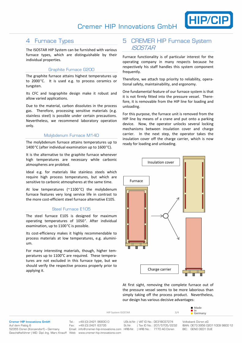
One fundamental feature of our furnace system is that
it is not firmly fitted into the pressure vessel. There-
fore, it is removable from the HIP line for loading and
unloading.
For this purpose, the furnace unit is removed from the
HIP line by means of a crane and put onto a parking
device. Now, the operator unlocks several locking
mechanisms between insulation cover and charge
carrier. In the next step, the operator takes the
insulation cover off the charge carrier, which is now
ready for loading and unloading.
At first sight, removing the complete furnace out of
the pressure vessel seems to be more laborious than
simply taking off the process product. Nevertheless,
our design has various decisive advantages:
Furnace
Insulation cover
Charge carrier
Cremer HIP Innovations GmbH
Auf dem Flabig 6
52355 Düren (Konzendorf) – Germany
Geschäftsführer | MD: Dipl.-Ing. Marc Knauff
Tel.: +49 (0) 2421 96830 0
Fax: +49 (0) 2421 63735
Email: [email protected]
Web: www.cremer-hip-innovations.com
USt.Id.Nr. | VAT ID No.: DE318037274
St.Nr. | Tax ID No.: 207/5705/2232
HRB-Nr. | HRB No.: 7770 AG Düren
Volksbank Düren eG
IBAN: DE73 3956 0201 1009 9800 12
BIC: GENO DED1 DUE
HIP System ISOSTAR 4/4
For ergonomic aspects, it makes sense to move the
charge carrier to comfortable working height for
loading and unloading instead of having to handle the
product bending down to reach the opened pressure
vessel. Depending on the application (e.g. aerospace,
medical technology) the furnace thermocouples must
be replaced frequently for maintenance or quality
assurance. The detached furnace allows the operator
quick and easy replacement of thermocouples or
individual heating elements. Furthermore, checking or
cleaning of the furnace and the interior of the pres-
sure vessel between process cycles is completely
barrier-free possible. Moreover, a second furnace can
be prepared i.e. loaded, while the HIP line is still under
process.
One major point crediting our furnace system is the
interchangeability of the furnace.
Various materials demand varying process tempera-
tures, thus stipulating miscellaneous requirements to
the furnace.
Consequently, our product range offers a graphite
furnace (G200), a molybdenum furnace (M140), and a
steel furnace (E105). Each individual furnace features
different properties, refer to point 4.
Generally, the issue with changing the furnace lies in
the fact that each furnace is equipped with proper
thermocouples (type K, S, C, etc.) depending on its
process temperature.
The possibility of changing from one furnace type to
another at any desired time is the outstanding feature
of our system. Changing the type of thermocouple for
temperature measurement is no issue in our system.
Mechanical refurbishment is not necessary. The
operator simply changes the system control to the
desired furnace.
Consequently, the operator is not tied to a certain
material group. On the contrary: various materials can
be processed with different furnace types.
Our system allows maximum flexibility, top capacity,
and optimum economy.
6 Rapid Cooling ISOCOOL
In HIP systems, rapid cooling is a common means to
increase productivity because it allows effective
reducing of cycle times. Therefore, our system always
provides rapid cooling. The operator can activate it if
desired to reduce the cooling down phase.
Basically, cooled process gas is conducted into the
process chamber, i.e. the furnace interior, to cool
down the charge as quick as possible. Obviously, the
charge must be cooled evenly and uniformly. Cooling
some parts of the charge quicker than others will
result in noticeably negative effects on process mate-
rial quality.
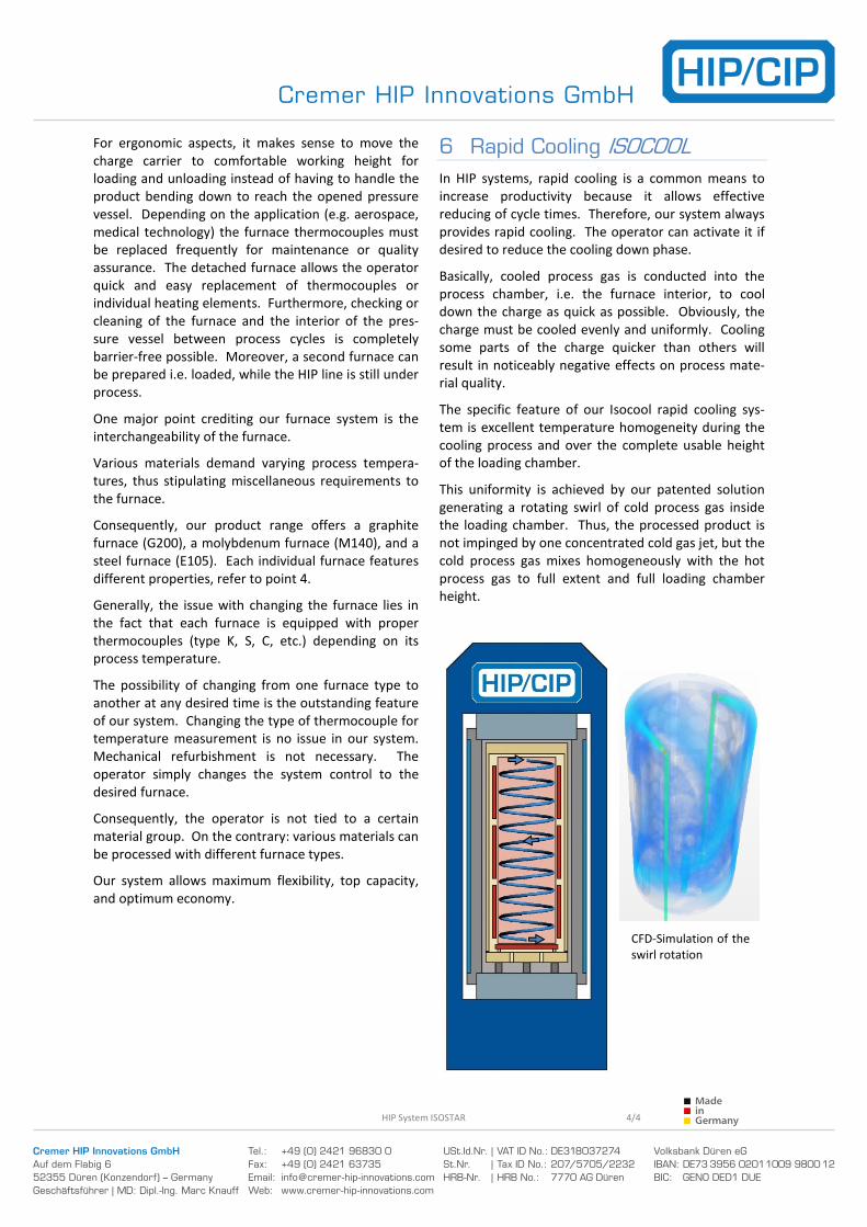
The specific feature of our Isocool rapid cooling sys-
tem is excellent temperature homogeneity during the
cooling process and over the complete usable height
of the loading chamber.
This uniformity is achieved by our patented solution
generating a rotating swirl of cold process gas inside
the loading chamber. Thus, the processed product is
not impinged by one concentrated cold gas jet, but the
cold process gas mixes homogeneously with the hot
process gas to full extent and full loading chamber
height.
CFD-Simulation of the
swirl rotation