Embed Size (px)
Citation preview
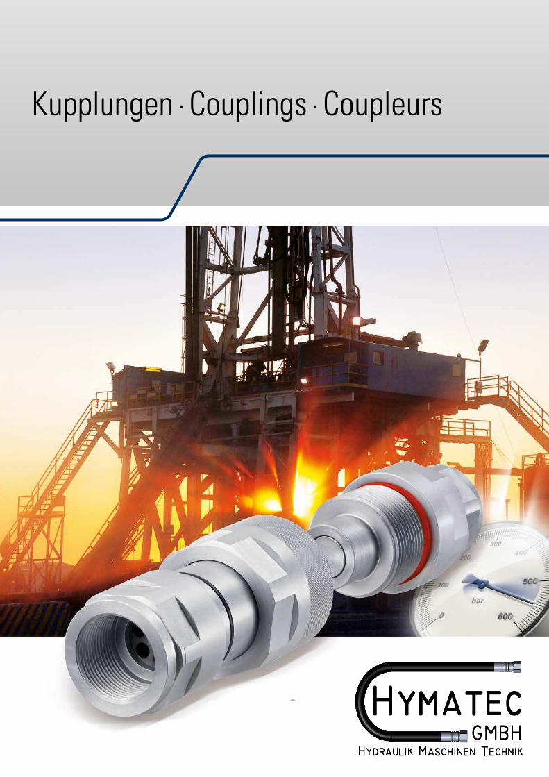
Kupplungen · Couplings · Coupleurs
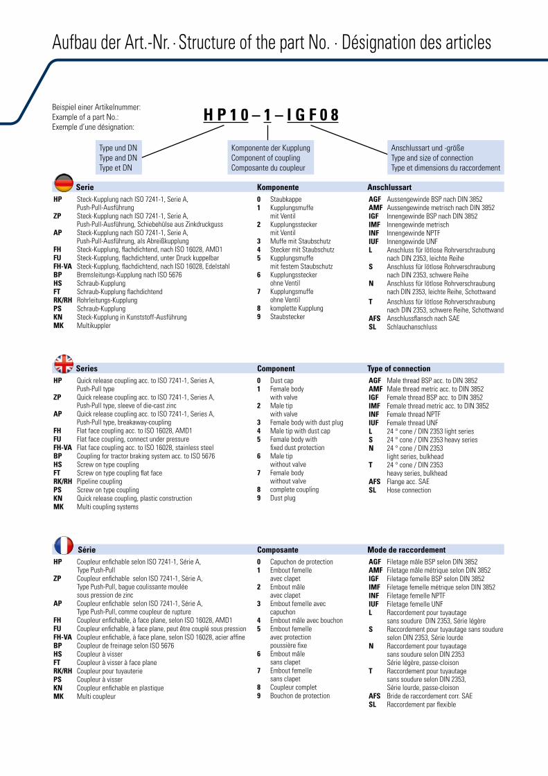
Beispiel einer Artikelnummer:Example of a part No.:Exemple d’une désignation:
0 Staubkappe1 Kupplungsmuffe
mit Ventil2 Kupplungsstecker
mit Ventil3 Muffe mit Staubschutz4 Stecker mit Staubschutz5 Kupplungsmuffe
mit festem Staubschutz6 Kupplungsstecker
ohne Ventil7 Kupplungsmuffe
ohne Ventil8 komplette Kupplung9 Staubstecker
0 Dust cap1 Female body
with valve2 Male tip
with valve3 Female body with dust plug4 Male tip with dust cap5 Female body with
fixed dust protection6 Male tip
without valve7 Female body
without valve8 complete coupling9 Dust plug
0 Capuchon de protection1 Embout femelle
avec clapet2 Embout mâle
avec clapet3 Embout femelle avec
capuchon4 Embout mâle avec bouchon5 Embout femelle
avec protectionpoussière fixe
6 Embout mâlesans clapet
7 Embout femellesans clapet
8 Coupleur complet9 Bouchon de protection
Type und DN Type and DN Type et DN
Komponente der Kupplung Component of coupling Composante du coupleur
Anschlussart und -größe Type and size of connection Type et dimensions du raccordement
H P 1 0 – 1 – I G F 0 8
Serie Komponente Anschlussart
Series Component Type of connection
Série Composante Mode de raccordement
HP Steck-Kupplung nach ISO 7241-1, Serie A, Push-Pull-Ausführung
ZP Steck-Kupplung nach ISO 7241-1, Serie A, Push-Pull-Ausführung, Schiebehülse aus Zinkdruckguss
AP Steck-Kupplung nach ISO 7241-1, Serie A,Push-Pull-Ausführung, als Abreißkupplung
FH Steck-Kupplung, flachdichtend, nach ISO 16028, AMD1FU Steck-Kupplung, flachdichtend, unter Druck kuppelbarFH-VA Steck-Kupplung, flachdichtend, nach ISO 16028, EdelstahlBP Bremsleitungs-Kupplung nach ISO 5676HS Schraub-KupplungFT Schraub-Kupplung flachdichtendRK/RH Rohrleitungs-KupplungPS Schraub-KupplungKN Steck-Kupplung in Kunststoff-AusführungMK Multikuppler
HP Quick release coupling acc. to ISO 7241-1, Series A, Push-Pull type
ZP Quick release coupling acc. to ISO 7241-1, Series A,Push-Pull type, sleeve of die-cast zinc
AP Quick release coupling acc. to ISO 7241-1, Series A,Push-Pull type, breakaway-coupling
FH Flat face coupling acc. to ISO 16028, AMD1FU Flat face coupling, connect under pressureFH-VA Flat face coupling acc. to ISO 16028, stainless steelBP Coupling for tractor braking system acc. to ISO 5676HS Screw on type couplingFT Screw on type coupling flat faceRK/RH Pipeline couplingPS Screw on type couplingKN Quick release coupling, plastic constructionMK Multi coupling systems
HP Coupleur enfichable selon ISO 7241-1, Série A, Type Push-Pull
ZP Coupleur enfichable selon ISO 7241-1, Série A,Type Push-Pull, bague coulissante mouléesous pression de zinc
AP Coupleur enfichable selon ISO 7241-1, Série A,Type Push-Pull, comme coupleur de rupture
FH Coupleur enfichable, à face plane, selon ISO 16028, AMD1FU Coupleur enfichable, à face plane, peut être couplé sous pressionFH-VA Coupleur enfichable, à face plane, selon ISO 16028, acier affineBP Coupleur de freinage selon ISO 5676HS Coupleur à visserFT Coupleur à visser à face planeRK/RH Coupleur pour tuyauteriePS Coupleur à visserKN Coupleur enfichable en plastiqueMK Multi coupleur
AGF Aussengewinde BSP nach DIN 3852AMF Aussengewinde metrisch nach DIN 3852IGF Innengewinde BSP nach DIN 3852IMF Innengewinde metrischINF Innengewinde NPTFIUF Innengewinde UNFL Anschluss für lötlose Rohrverschraubung
nach DIN 2353, leichte ReiheS Anschluss für lötlose Rohrverschraubung
nach DIN 2353, schwere ReiheN Anschluss für lötlose Rohrverschraubung
nach DIN 2353, leichte Reihe, Schottwand
T Anschluss für lötlose Rohrverschraubungnach DIN 2353, schwere Reihe, Schottwand
AFS Anschlussflansch nach SAESL Schlauchanschluss
AGF Male thread BSP acc. to DIN 3852AMF Male thread metric acc. to DIN 3852IGF Female thread BSP acc. to DIN 3852IMF Female thread metric acc. to DIN 3852INF Female thread NPTFIUF Female thread UNFL 24 ° cone / DIN 2353 light seriesS 24 ° cone / DIN 2353 heavy seriesN 24 ° cone / DIN 2353
light series, bulkheadT 24 ° cone / DIN 2353
heavy series, bulkheadAFS Flange acc. SAESL Hose connection
AGF Filetage mâle BSP selon DIN 3852AMF Filetage mâle métrique selon DIN 3852IGF Filetage femelle BSP selon DIN 3852IMF Filetage femelle métrique selon DIN 3852INF Filetage femelle NPTFIUF Filetage femelle UNFL Raccordement pour tuyautage
sans soudure DIN 2353, Série légèreS Raccordement pour tuyautage sans soudure
selon DIN 2353, Série lourdeN Raccordement pour tuyautage
sans soudure selon DIN 2353Série légère, passe-cloison
T Raccordement pour tuyautage sans soudure selon DIN 2353,Série lourde, passe-cloison
AFS Bride de raccordement corr. SAESL Raccordement par flexible
Aufbau der Art.-Nr. · Structure of the part No. · Désignation des articles
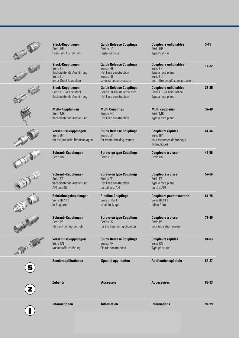
1
Steck-Kupplungen Serie HPPush-Pull-Ausführung
Coupleurs enfichables Série HPType Push-Pull
3-15Quick Release Couplings Series HPPush-Pull type
17-32
33-35
Steck-Kupplungen Serie FHlachdichtende AusführungSerie FUunter Druck kuppelbar
Steck-Kupplungen Serie FH-VA Edelstahllachdichtende Ausführung
Quick Release CouplingsSeries FHFlat Face constructionSeries FUconnect under pressure
Quick Release CouplingsSeries FH-VA stainless steelFlat Face construction
Coupleurs enfichablesSérie FHType à face planeSérie FUpeut ´̀etre couplé sous pression
Coupleurs enfichablesSérie FH-VA acier afinéType à face plane
37-40Multi-Kupplungen Serie MKlachdichtende Ausführung
Multi Couplings Series MKFlat Face construction
Multi coupleurs Série MKType à face plane
41-44Verschlusskupplungen Serie BPfür hydraulische Bremsanlagen
Quick Release Couplings Series BPfor tractor braking system
Coupleurs rapides Série BPpour systèmes de freinage hydrauliques
45-56Schraub-Kupplungen Serie HS
Screw-on type Couplings Series HS
Coupleurs à visser Série HS
57-66
77-80
Schraub-Kupplungen Serie FTlachdichtende AusführungAPI geprüft
Schraub-Kupplungen Serie PSfür den Hammerbetrieb
Screw-on type Couplings Series FTFlat Face constructiontested acc. API
Screw-on type Couplings Series PSfor the hammer application
Coupleurs à visser Série FTType à face planetesté a API
Coupleurs à visser Série PSpour utilisation sévère
67-75Rohrleitungskupplungen Serie RK/RHleckagearm
Pipeline CouplingsSeries RK/RHsmall leakage
Coupleurs pour tuyauterieSérie RK/RHfaible fuite
81-83
85-87
Verschlusskupplungen Serie KNKunststoffausführung
Sonderapplikationen Special application Application spéciale
Quick Release Couplings Series KNPlastic construction
Coupleurs rapides Série KNType plastique
89-93
94-99
Zubehör AccessoiresAccessory
Informationen Information Informations
2
VOSWINKEL-Kupplungen bewähren sich seit vielen Jahren in der Praxis beim Einsatz in der Hydraulik. Die hohe Qualität der Kupplungen ist das Ergebnis ständiger Produktpflege, bei der auch die Erfahrungen der Anwender berücksichtigt werden. Der hohe Fertigungsstandard, kombiniert mit dem Qualitätsmanagement nach EN ISO 9001, sichert die Qualität unserer Produkte.
Die technischen Daten der einzelnen Kupplungen entnehmen Sie bitte den folgenden Seiten des Kataloges. Für die Kupplungen der Serien HP, HS, FH, HA, BP und RK/RH gelten folgende Merkmale:
Gehäusewerkstoff: Stahl entspr. EN 10277,Beschichtung: Cr (III), Kupplungen der Serie FH, FU, MK, FT und RK/RH: Zink-Nickel
Dichtungen:NBR/PTFE ISO 3601
Betriebstemperatur:- 20 °C bis + 100 °C mit NBR- 25 °C bis + 200 °C mit FKM
Mitgeltende Normen:EN ISO 8330:2000, ISO 5675, ISO5676, ISO 7241, ISO 16028, AMD 1
Für andere Werkstoffkombinationenerbitten wir Ihre Anfrage.
Die in unserem Katalog genannten Betriebs-drücke beziehen sich auf die Festigkeit der Gehäusebauteile. Genormte Anschlussformen können andere Nenndrücke aufweisen, diese sind nicht zwangsläuig auf den Kupplungstypen anzuwenden.
Umbauten, sowie Veränderungen unserer Hydrau-likkupplungen sind unzulässig. Zu verwenden sind ausschließlich Voswinkel Ersatzteile. Anderwei-tiges Vorgehen und Demontage führt zum Verlust der Gewährleistungs- und Schadensersatzan-sprüche.
Die Voswinkel Hydraulikkupplungen fallen nicht unter die Richtlinie 94/9/EG zur bestimmungs-gemäßen Verwendung in explosionsgefährdeten Bereichen. Die Hydraulikkupplungen haben keine eigene Zündquelle, durch die ein Entlammen entstehen könnte.
Im Zuge der Produktplege behalten wir uns technische Änderungen vor.
VOSWINKEL couplings have proven their value for many years in practical use in hydraulic systems. The excellent quality of the couplings is the result of continual pro- duct improvement in which the experiences of users have been taken into considera-tion, as well. Our high production standards, combined with our quality management system certified in accordance with EN ISO 9001, assures the quality of our products.
For the technical speciications of the individual couplings please refer to the following pages of the catalog. The couplings of the series HP, HS, FH, HA, BP and RK/RH have the following common characteristics:
Housing material:Steel according to EN 10277,Coating: Cr (III), Couplings Series FH, FU, MK, FT and RK/RH: Zinc-Nickel
Seals:NBR/PTFE ISO 3601
Operating temperature:- 20 °C to + 100 °C with NBR- 25 °C to + 200 °C with FKM
Normative references:EN ISO 8330:2000, ISO 5675, ISO5676, ISO 7241, ISO 16028, AMD 1
We invite your inquiry to require othercombinations of materials.
The operating pressures speciied in our catalog relate to the strength of the housing compo-nents. Standardized connector shapes may have other rated pressures, which cannot automati-cally be applied to the particular coupling type.
Any remodeling and modiication of the cou-plings are prohibited. By any maintenance of our couplings it’s necessary to use original Voswinkel parts. In case of using of no original parts or disassembling of the couplings the warranty will be expire.
The Voswinkel hydraulic couplings don’t have the 94/7/EG guidance for the using in explosive ield. The couplings don’t have an own ignition source which could be a reason of inlame.
We reserve the right of any technical changes due to product improvements.
Les coupleurs VOSWINKEL sont connus depuis de très nombreuses années dans le domaine de l’hydraulique mobile. La qualité des coupleurs est le fruit d’une constante amélioration du produit et pour laquelle on a tenu compte de l’expérience de l’utilisateur combinée avec une réalisation moderne. Le standard de fabrication élevé combiné avec un management de qualité selon EN ISO 9001 garantit la qualité de nos produits.
Vous trouverez dans les pages suivantes du catalogue les données techniques des différents coupleurs. Pour les séries HP, HS, FH, HA, BP et RK/RH les caractéristiques suivantes sont valables:
Matériau du corps:Acier suivant norme EN 10277Revêtement: Cr (III), Coupleurs Série FH, FU, MK, FT et RK/RH: Zinc-Nickel
Joints:NBR/PTFE ISO 3601
Température de service:- 20 °C à + 100 °C avec NBR- 25 °C à + 200 °C avec FKM
Références:EN ISO 8330:2000, ISO 5675, ISO5676, ISO 7241, ISO 16028, AMD 1
Autres combinaisons de matériauxsur demande.
Les pressions de service mentionnées dans notre catalogue se rapportent à la résistance des composants de boîtiers. Des formes normées de raccord peuvent présenter d’autres pressions nominales, elles ne sont pas conseil-lées sur ces types de coupleurs.
Les transformations ou modiications de nos accouplements hydrauliques sont interdites. Seules des pièces de rechange Voswinkel peuvent être utilisées. Toute autre manipulation ou démontage entraîne une perte de la garantie et des droits aux dommages et intérêts.
Les coupleurs hydrauliques Voswinkel ne sont pas soumis à la directive 94/9/EC concernant la bonne utilisation en atmosphère explosive. Les coupleurs hydrauliques ne présentent aucune source d’ignition pouvant provoquer une lamme.Nous nous réservons le droit de procéder à des modiications techniques pour le développement de nos produits.
Einleitung · Introduction · Introduction
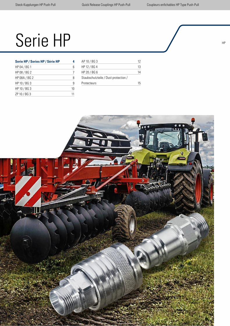
Serie HPSerie HP / Series HP / Série HP 4
HP 04 / BG 1 6
HP 08 / BG 2 7
HP 08A / BG 2 8
HP 10 / BG 3 9
HP 10 / BG 3 10
ZP 10 / BG 3 11
AP 10 / BG 3 12
HP 12 / BG 4 13
HP 20 / BG 6 14
Staubschutzteile / Dust protection /
Protecteurs 15
Steck-Kupplungen HP Push-Pull Quick Release Couplings HP Push-Pull Coupleurs enichables HP Type Push-Pull
HP
4
Steck-Kupplungen HP Push-Pull Quick Release Couplings HP Push-Pull Coupleurs enichables HP Type Push-Pull
Die doppelt wirkende Schiebehülse ist in der Verriegelungsstellung durch eine vorgespannte Feder ixiert. Sie kann zum Kuppeln oder Ent-kuppeln in beide Richtungen axial verschoben werden. Die beiden Hälften der Steckkupp-lung werden durch Rastkugeln miteinander verriegelt.
Die Schiebehülse kann mit Sprengringen in eine Schottwand eingebaut werden. Somit erhält die Muffe die Funktion einer Abreiß-kupplung. Falls ein Stecker von einer so montierten Muffe abgerissen wird, wird das System automatisch entkuppelt und die Ventile schließen sich, so dass eine Beschädigung der Schlauchleitung und ein eventueller Ölverlust vermieden werden.
VOSWINKEL bietet eine breite Produktpalette für den Landmaschinenbereich sowie für die Fahrzeug- und Baumaschinenhydraulik. Durch die modulare Bauweise steht eine große Aus-wahl von Anschlüssen, die den internationalen Normen entsprechen, zur Verfügung.
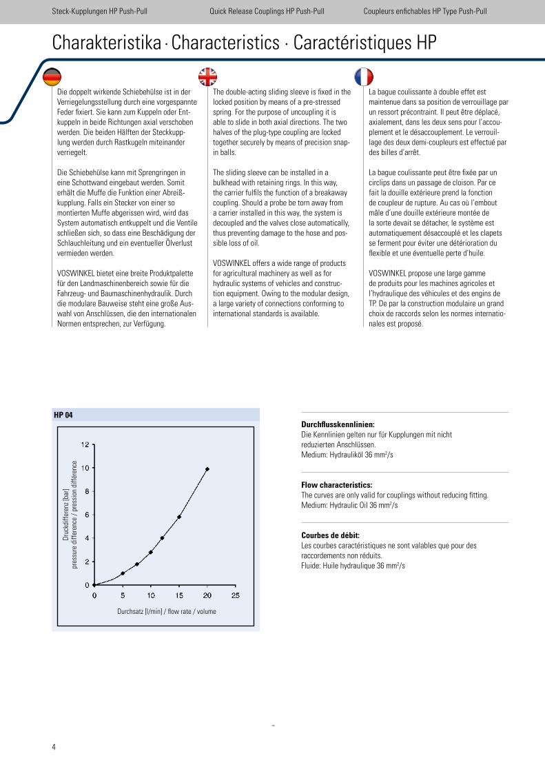
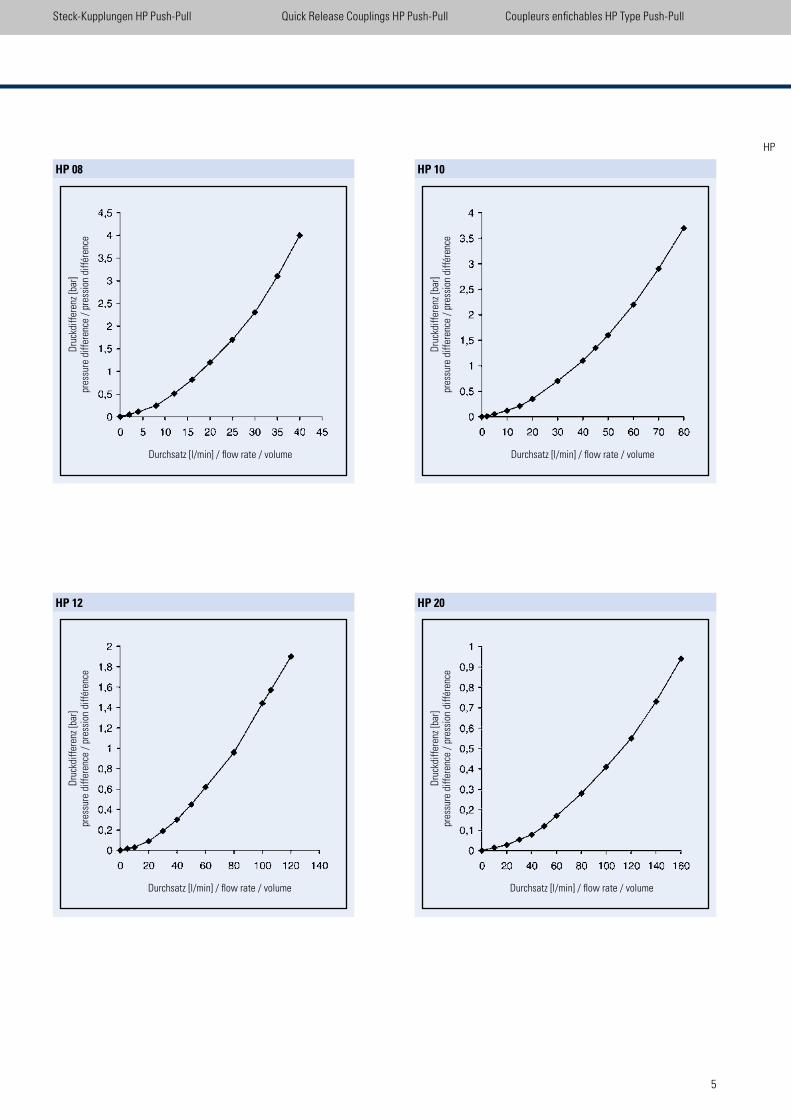
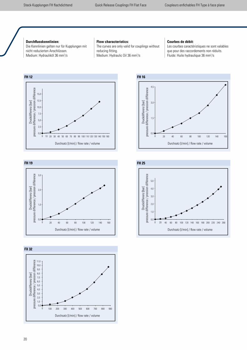
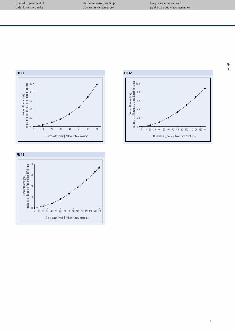
Durchflusskennlinien: Die Kennlinien gelten nur für Kupplungen mit nichtreduzierten Anschlüssen. Medium: Hydrauliköl 36 mm2/s
Flow characteristics: The curves are only valid for couplings without reducing itting. Medium: Hydraulic Oil 36 mm2/s
Courbes de débit: Les courbes caractéristiques ne sont valables que pour des raccordements non réduits. Fluide: Huile hydraulique 36 mm2/s
The double-acting sliding sleeve is ixed in the locked position by means of a pre-stressed spring. For the purpose of uncoupling it is able to slide in both axial directions. The two halves of the plug-type coupling are locked together securely by means of precision snap-in balls.
The sliding sleeve can be installed in a bulkhead with retaining rings. In this way, the carrier fulils the function of a breakaway coupling. Should a probe be torn away from a carrier installed in this way, the system is decoupled and the valves close automatically, thus preventing damage to the hose and pos-sible loss of oil.
VOSWINKEL offers a wide range of products for agricultural machinery as well as for hydraulic systems of vehicles and construc-tion equipment. Owing to the modular design, a large variety of connections conforming to international standards is available.
La bague coulissante à double effet est maintenue dans sa position de verrouillage par un ressort précontraint. Il peut être déplacé, axialement, dans les deux sens pour l’accou-plement et le désaccouplement. Le verrouil-lage des deux demi-coupleurs est effectué par des billes d’arrêt.
La bague coulissante peut être ixée par un circlips dans un passage de cloison. Par ce fait la douille extérieure prend la fonction de coupleur de rupture. Au cas où l’embout mâle d’une douille extérieure montée de la sorte devait se détacher, le système est automatiquement désaccouplé et les clapets se ferment pour éviter une détérioration du lexible et une éventuelle perte d’huile.
VOSWINKEL propose une large gamme de produits pour les machines agricoles et l’hydraulique des véhicules et des engins de TP. De par la construction modulaire un grand choix de raccords selon les normes internatio-nales est proposé.
Charakteristika · Characteristics · Caractéristiques HP
HP 04
Dru
ckdi
ffer
enz
[bar
]pr
essu
re d
iffer
ence
/ p
ress
ion
diff
éren
ce
Durchsatz [l/min] / low rate / volume
5
Steck-Kupplungen HP Push-Pull Quick Release Couplings HP Push-Pull Coupleurs enichables HP Type Push-Pull
HP 08 HP 10
HP 12 HP 20
Dru
ckdi
ffer
enz
[bar
]pr
essu
re d
iffer
ence
/ p
ress
ion
diff
éren
ce
Durchsatz [l/min] / low rate / volume Durchsatz [l/min] / low rate / volume
Durchsatz [l/min] / low rate / volume Durchsatz [l/min] / low rate / volume
Dru
ckdi
ffer
enz
[bar
]pr
essu
re d
iffer
ence
/ p
ress
ion
diff
éren
ce
Dru
ckdi
ffer
enz
[bar
]pr
essu
re d
iffer
ence
/ p
ress
ion
diff
éren
ce
Dru
ckdi
ffer
enz
[bar
]pr
essu
re d
iffer
ence
/ p
ress
ion
diff
éren
ce
HP
6
Betriebsdruck Pmax
25 MPa (250 bar)
Berstdruck Pgekuppelt
1000 bar P
Muffe 1000 bar
PStecker
1000 bar
Oberfläche Chrom III (Zn-Fe)
Dichtungen NBR, PTFE
Bei genormten Gewindeanschlüssen ist bei der Festlegung des Betriebsdruckes der höchstzulässige Betriebsdruck des Anschlusses zu berücksichtigen. NW 6,3.
Working Pressure Pmax
25 MPa (250 bar)
Bursting pressure Pconnected
1000 bar P
Female body 1000 bar
PMale tip
1000 bar
Coating Chrom III (Zn-Fe)
Sealings NBR, PTFE
With standard threaded connections, the working pressure is determined by the highest permissible rated pressure.Size 6,3.
Pression de service Pmax
25 MPa (250 bar)
Pression de Pcouplé
1000 bardéflagration P
Embout femelle 1000 bar
PEmbout mâle
1000 bar
Revêtement Chrom III (Zn-Fe)
Joints NBR, PTFE
Avec les raccords iletés normés, la pression de service est déterminée en tenant compte de la pression de service max. admissible.Taille 6,3.
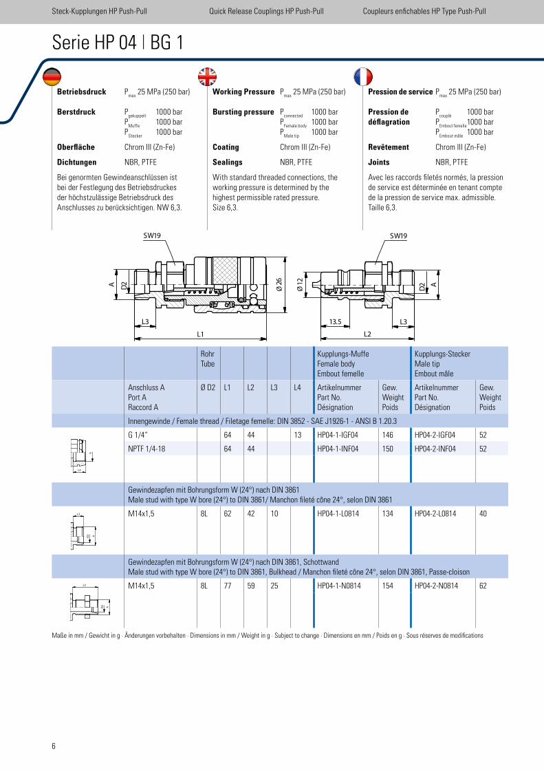
Serie HP 04 | BG 1
RohrTube
Kupplungs-MuffeFemale bodyEmbout femelle
Kupplungs-SteckerMale tipEmbout mâle
Anschluss APort ARaccord A
Ø D2 L1 L2 L3 L4 ArtikelnummerPart No.Désignation
Gew.WeightPoids
ArtikelnummerPart No.Désignation
Gew.WeightPoids
Innengewinde / Female thread / Filetage femelle: DIN 3852 - SAE J1926-1 - ANSI B 1.20.3
G 1/4“ 64 44 13 HP04-1-IGF04 146 HP04-2-IGF04 52
NPTF 1/4-18 64 44 HP04-1-INF04 150 HP04-2-INF04 52
Gewindezapfen mit Bohrungsform W (24°) nach DIN 3861Male stud with type W bore (24°) to DIN 3861/ Manchon ileté cône 24°, selon DIN 3861
M14x1,5 8L 62 42 10 HP04-1-L0814 134 HP04-2-L0814 40
Gewindezapfen mit Bohrungsform W (24°) nach DIN 3861, SchottwandMale stud with type W bore (24°) to DIN 3861, Bulkhead / Manchon ileté cône 24°, selon DIN 3861, Passe-cloison
M14x1,5 8L 77 59 25 HP04-1-N0814 154 HP04-2-N0814 62
Maße in mm / Gewicht in g · Änderungen vorbehalten · Dimensions in mm / Weight in g · Subject to change · Dimensions en mm / Poids en g · Sous réserves de modiications
Steck-Kupplungen HP Push-Pull Quick Release Couplings HP Push-Pull Coupleurs enichables HP Type Push-Pull
A D2
L3
L1
26
�
SW19
12
�
13.5 L3
L2
A
D2
SW19
ØØ
L4
A
L3
7
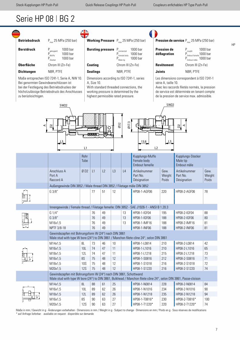
Betriebsdruck Pmax
25 MPa (250 bar)
Berstdruck Pgekuppelt
1000 bar P
Muffe 1000 bar
PStecker
1000 bar
Oberfläche Chrom III (Zn-Fe)
Dichtungen NBR, PTFE
Maße entsprechen ISO 7241-1, Serie A, NW 10.Bei genormten Gewindeanschlüssen ist bei der Festlegung des Betriebsdruckes der höchstzulässige Betriebsdruck des Anschlusses zu berücksichtigen.
Working Pressure Pmax
25 MPa (250 bar)
Bursting pressure Pconnected
1000 bar P
Female body 1000 bar
PMale tip
1000 bar
Coating Chrom III (Zn-Fe)
Sealings NBR, PTFE
Dimensions according to ISO 7241-1, series A, Size 10. With standard threaded connections, the working pressure is determined by the highest permissible rated pressure.
Pression de service Pmax
25 MPa (250 bar)
Pression de Pcouplé
1000 bardéflagration P
Embout femelle 1000 bar
PEmbout mâle
1000 bar
Revêtement Chrom III (Zn-Fe)
Joints NBR, PTFE
Les dimensions correspondent à ISO 7241-1 série A, taille 10. Avec les raccords iletés normés, la pression de service est déterminée en tenant compte de la pression de service max. admissible.
Serie HP 08 | BG 2
RohrTube
Kupplungs-MuffeFemale bodyEmbout femelle
Kupplungs-SteckerMale tipEmbout mâle
Anschluss APort ARaccord A
Ø D2 L1 L2 L3 L4 ArtikelnummerPart No.Désignation
Gew.WeightPoids
ArtikelnummerPart No.Désignation
Gew.WeightPoids
Außengewinde DIN 3852 / Male thread DIN 3852 / Filetage mâle DIN 3852
G 3/8“ 77 51 12 HP08-1-AGF06 220 HP08-2-AGF06 78
Innengewinde / Female thread / Filetage femelle: DIN 3852 - SAE J1926-1 - ANSI B 1.20.3
G 1/4“ 76 49 13 HP08-1-IGF04 195 HP08-2-IGF04 88
G 3/8“ 76 49 13 HP08-1-IGF06 188 HP08-2-IGF06 80
M16x1,5 76 49 13 HP08-1-IMF16 188 HP08-2-IMF16 81
NPTF 3/8-18 76 49 HP08-1-INF06 188 HP08-2-INF06 81
Gewindezapfen mit Bohrungsform W (24°) nach DIN 3861Male stud with type W bore (24°) to DIN 3861 / Manchon ilete cône 24°, selon DIN 3861
M14x1,5 8L 73 46 10 HP08-1-L0814 210 HP08-2-L0814 42
M16x1,5 10L 74 47 11 HP08-1-L1016 210 HP08-2-L1016 65
M18x1,5 12L 74 47 11 HP08-1-L1218 215 HP08-2-L1218 73
M16x1,5 8S 75 48 12 HP08-1-S0816 212 HP08-2-S0816 71
M18x1,5 10S 75 48 12 HP08-1-S1018 216 HP08-2-S1018 72
M20x1,5 12S 75 48 12 HP08-1-S1220 216 HP08-2-S1220 74
Gewindezapfen mit Bohrungsform W (24°) nach DIN 3861, SchottwandMale stud with type W bore (24°) to DIN 3861, Bulkhead / Manchon ilete cône 24°, selon DIN 3861, Passe-cloison
M14x1,5 8L 88 61 25 HP08-1-N0814 228 HP08-2-N0814 84
M16x1,5 10L 89 62 26 HP08-1-N1016 234 HP08-2-N1016 90
M18x1,5 12L 89 62 26 HP08-1-N1218 235 HP08-2-N1218 94
M16x1,5 8S 90 63 27 HP08-1-T0816* 230 HP08-2-T0816* 100
M20x1,5 12S 90 63 27 HP08-1-T1220* 220 HP08-2-T1220* 74
Steck-Kupplungen HP Push-Pull Quick Release Couplings HP Push-Pull Coupleurs enichables HP Type Push-Pull
HP
L3
L1
A
D2
�
SW22
17
.3�
13.8 L3
L2
A
D2
SW22
Ø3
2
Ø
L4
A
L3
A
L3
Maße in mm / Gewicht in g · Änderungen vorbehalten · Dimensions in mm / Weight in g · Subject to change · Dimensions en mm / Poids en g · Sous réserves de modiications* auf Anfrage lieferbar · available on request · disponible sur demande
8
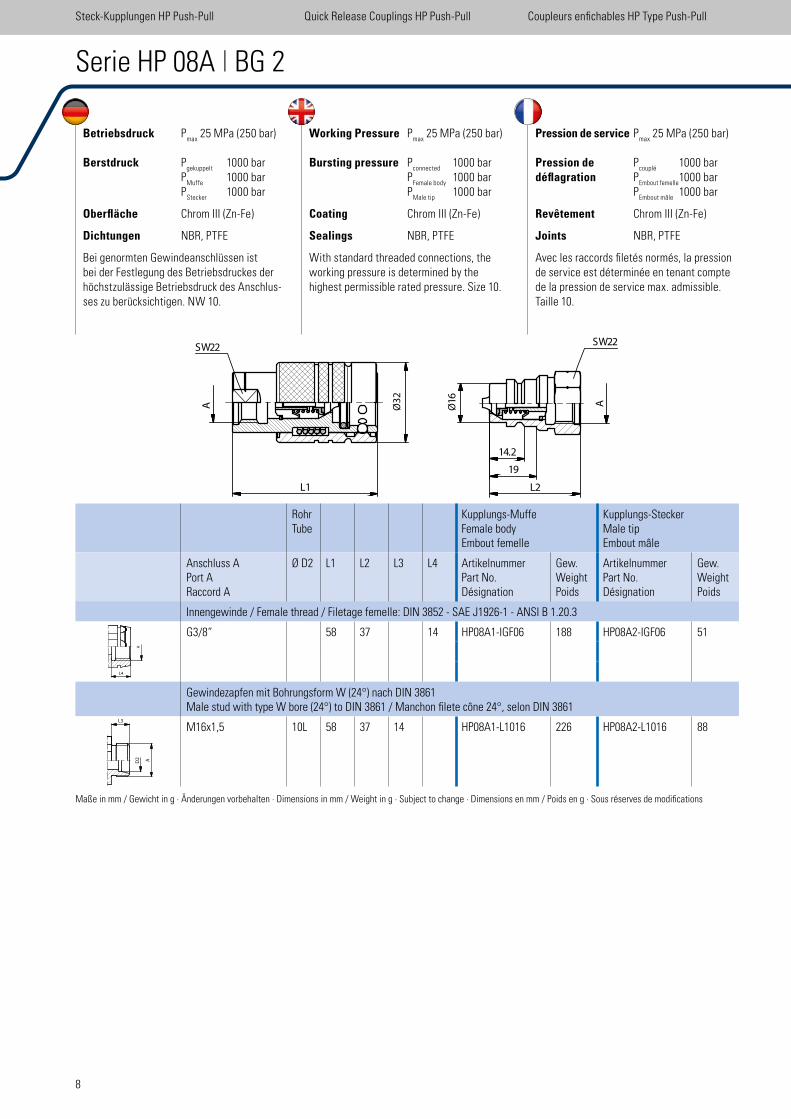
Betriebsdruck Pmax
25 MPa (250 bar)
Berstdruck Pgekuppelt
1000 bar P
Muffe 1000 bar
PStecker
1000 bar
Oberfläche Chrom III (Zn-Fe)
Dichtungen NBR, PTFE
Bei genormten Gewindeanschlüssen ist bei der Festlegung des Betriebsdruckes der höchstzulässige Betriebsdruck des Anschlus-ses zu berücksichtigen. NW 10.
Working Pressure Pmax
25 MPa (250 bar)
Bursting pressure Pconnected
1000 bar P
Female body 1000 bar
PMale tip
1000 bar
Coating Chrom III (Zn-Fe)
Sealings NBR, PTFE
With standard threaded connections, the working pressure is determined by the highest permissible rated pressure. Size 10.
Pression de service Pmax
25 MPa (250 bar)
Pression de Pcouplé
1000 bardéflagration P
Embout femelle 1000 bar
PEmbout mâle
1000 bar
Revêtement Chrom III (Zn-Fe)
Joints NBR, PTFE
Avec les raccords iletés normés, la pression de service est déterminée en tenant compte de la pression de service max. admissible.Taille 10.
Serie HP 08A | BG 2
Maße in mm / Gewicht in g · Änderungen vorbehalten · Dimensions in mm / Weight in g · Subject to change · Dimensions en mm / Poids en g · Sous réserves de modiications
Steck-Kupplungen HP Push-Pull Quick Release Couplings HP Push-Pull Coupleurs enichables HP Type Push-Pull
RohrTube
Kupplungs-MuffeFemale bodyEmbout femelle
Kupplungs-SteckerMale tipEmbout mâle
Anschluss APort ARaccord A
Ø D2 L1 L2 L3 L4 ArtikelnummerPart No.Désignation
Gew.WeightPoids
ArtikelnummerPart No.Désignation
Gew.WeightPoids
Innengewinde / Female thread / Filetage femelle: DIN 3852 - SAE J1926-1 - ANSI B 1.20.3
G3/8“ 58 37 14 HP08A1-IGF06 188 HP08A2-IGF06 51
Gewindezapfen mit Bohrungsform W (24°) nach DIN 3861Male stud with type W bore (24°) to DIN 3861 / Manchon ilete cône 24°, selon DIN 3861
M16x1,5 10L 58 37 14 HP08A1-L1016 226 HP08A2-L1016 88
SW22SW22
A
L1
�
16
�14.2
19
L2
AØ3
2
Ø
L4
A
L3
9
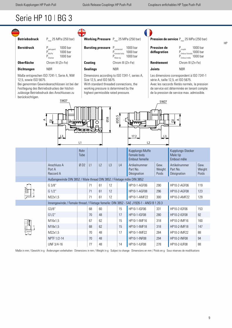
Betriebsdruck Pmax
25 MPa (250 bar)
Berstdruck Pgekuppelt
1000 bar P
Muffe 1000 bar
PStecker
1000 bar
Oberfläche Chrom III (Zn-Fe)
Dichtungen NBR
Maße entsprechen ISO 7241-1, Serie A, NW 12,5, sowie ISO 5675. Bei genormten Gewindeanschlüssen ist bei der Festlegung des Betriebsdruckes der höchst-zulässige Betriebsdruck des Anschlusses zu berücksichtigen.
Working Pressure Pmax
25 MPa (250 bar)
Bursting pressure Pconnected
1000 bar P
Female body 1000 bar
PMale tip
1000 bar
Coating Chrom III (Zn-Fe)
Sealings NBR
Dimensions according to ISO 7241-1, series A, Size 12,5, and ISO 5675.With standard threaded connections, the working pressure is determined by the highest permissible rated pressure.
Pression de service Pmax
25 MPa (250 bar)
Pression de Pcouplé
1000 bardéflagration P
Embout femelle 1000 bar
PEmbout mâle
1000 bar
Revêtement Chrom III (Zn-Fe)
Joints NBR
Les dimensions correspondent à ISO 7241-1 série A, taille 12,5, et ISO 5675.Avec les raccords iletés normés, la pression de service est déterminée en tenant compte de la pression de service max. admissible.
Serie HP 10 | BG 3
RohrTube
Kupplungs-MuffeFemale bodyEmbout femelle
Kupplungs-SteckerMale tipEmbout mâle
Anschluss APort ARaccord A
Ø D2 L1 L2 L3 L4 ArtikelnummerPart No.Désignation
Gew.WeightPoids
ArtikelnummerPart No.Désignation
Gew.WeightPoids
Außengewinde DIN 3852 / Male thread DIN 3852 / Filetage mâle DIN 3852
G 3/8“ 71 61 12 HP10-1-AGF06 290 HP10-2-AGF06 119
G 1/2“ 71 61 12 HP10-1-AGF08 296 HP10-2-AGF08 123
M22x1,5 71 61 12 HP10-1-AMF22 300 HP10-2-AMF22 129
Innengewinde / Female thread / Filetage femelle: DIN 3852 - SAE J1926-1 - ANSI B 1.20.3
G3/8“ 68 60 15 HP10-1-IGF06 331 HP10-2-IGF06 153
G1/2“ 70 48 17 HP10-1-IGF08 280 HP10-2-IGF08 92
M16x1,5 67 62 15 HP10-1-IMF16 318 HP10-2-IMF16 160
M18x1,5 68 62 15 HP10-1-IMF18 318 HP10-2-IMF18 147
M22x1,5 70 48 17 HP10-1-IMF22 284 HP10-2-IMF22 88
NPTF 1/2-14 70 48 HP10-1-INF08 294 HP10-2-INF08 94
UNF 3/4-16 77 48 14 HP10-1-IUF08 278 HP10-2-IUF08 88
Maße in mm / Gewicht in g · Änderungen vorbehalten · Dimensions in mm / Weight in g · Subject to change · Dimensions en mm / Poids en g · Sous réserves de modiications
Steck-Kupplungen HP Push-Pull Quick Release Couplings HP Push-Pull Coupleurs enichables HP Type Push-Pull
HP
SW27 SW27
L3
L1
A
D2 20
.6�
17.2 L3
L2
A
D2
Ø3
8
Ø
A
L3
L4
20.5
10
Betriebsdruck Pmax
25 MPa (250 bar)
Berstdruck Pgekuppelt
1000 bar P
Muffe 1000 bar
PStecker
1000 bar
Oberfläche Chrom III (Zn-Fe)
Dichtungen NBR
Maße entsprechen ISO 7241-1, Serie A, NW 12,5, sowie ISO 5675. Bei genormten Gewindeanschlüssen ist beider Festlegung des Betriebsdruckes der höchst-zulässige Betriebsdruck des Anschlusses zu berücksichtigen.
Working Pressure Pmax
25 MPa (250 bar)
Bursting pressure Pconnected
1000 bar P
Female body 1000 bar
PMale tip
1000 bar
Coating Chrom III (Zn-Fe)
Sealings NBR
Dimensions according to ISO 7241-1, series A, Size 12,5, and ISO 5675.With standard threaded connections, the working pressure is determined by the high-est permissible rated pressure.
Pression de service Pmax
25 MPa (250 bar)
Pression de Pcouplé
1000 bardéflagration P
Embout femelle 1000 bar
PEmbout mâle
1000 bar
Revêtement Chrom III (Zn-Fe)
Joints NBR
Les dimensions correspondent à ISO 7241-1 série A, taille 12,5, et ISO 5675.Avec les raccords iletés normés, la pression de service est déterminée en tenant compte de la pression de service max. admissible.
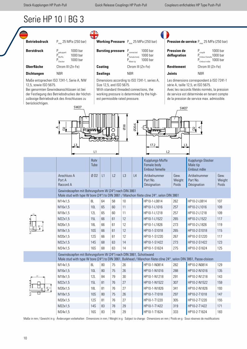
Serie HP 10 | BG 3
RohrTube
Kupplungs-MuffeFemale bodyEmbout femelle
Kupplungs-SteckerMale tipEmbout mâle
Anschluss APort ARaccord A
Ø D2 L1 L2 L3 L4 ArtikelnummerPart No.Désignation
Gew.WeightPoids
ArtikelnummerPart No.Désignation
Gew.WeightPoids
Gewindezapfen mit Bohrungsform W (24°) nach DIN 3861Male stud with type W bore (24°) to DIN 3861 / Manchon ilete cône 24°, selon DIN 3861
M14x1,5 8L 64 58 10 HP10-1-L0814 262 HP10-2-L0814 107
M16x1,5 10L 65 60 11 HP10-1-L1016 257 HP10-2-L1016 109
M18x1,5 12L 65 60 11 HP10-1-L1218 257 HP10-2-L1218 109
M22x1,5 15L 66 61 12 HP10-1-L1522 265 HP10-2-L1522 117
M26x1,5 18L 66 61 12 HP10-1-L1826 273 HP10-2-L1826 119
M18x1,5 10S 66 61 12 HP10-1-S1018 265 HP10-2-S1018 115
M20x1,5 12S 66 61 12 HP10-1-S1220 267 HP10-2-S1220 117
M22x1,5 14S 68 63 14 HP10-1-S1422 273 HP10-2-S1422 123
M24x1,5 16S 68 63 14 HP10-1-S1624 275 HP10-2-S1624 125
Gewindezapfen mit Bohrungsform W (24°) nach DIN 3861, SchottwandMale stud with type W bore (24°) to DIN 3861, Bulkhead / Manchon ilete cône 24°, selon DIN 3861, Passe-cloison
M14x1,5 8L 80 75 26 HP10-1-N0814 282 HP10-2-N0814 129
M16x1,5 10L 80 75 26 HP10-1-N1016 288 HP10-2-N1016 135
M18x1,5 12L 84 79 30 HP10-1-N1218 291 HP10-2-N1218 143
M22x1,5 15L 81 76 27 HP10-1-N1522 307 HP10-2-N1522 159
M26x1,5 18L 81 76 27 HP10-1-N1826 341 HP10-2-N1826 193
M18x1,5 10S 80 75 26 HP10-1-T1018 297 HP10-2-T1018 147
M20x1,5 12S 81 76 27 HP10-1-T1220 305 HP10-2-T1220 155
M22x1,5 14S 83 78 29 HP10-1-T1422 319 HP10-2-T1422 171
M24x1,5 16S 83 78 29 HP10-1-T1624 333 HP10-2-T1624 183
Maße in mm / Gewicht in g · Änderungen vorbehalten · Dimensions in mm / Weight in g · Subject to change · Dimensions en mm / Poids en g · Sous réserves de modiications
Steck-Kupplungen HP Push-Pull Quick Release Couplings HP Push-Pull Coupleurs enichables HP Type Push-Pull
SW27 SW27
L3
L1
A
D2 20
.6�
17.2 L3
L2
A
D2
Ø3
8
Ø
A
L3
11
Betriebsdruck Pmax
25 MPa (250 bar)
Berstdruck Pgekuppelt
1000 bar P
Muffe 1000 bar
PStecker
1000 bar
Oberfläche Chrom III (Zn-Fe)
Dichtungen NBR
Maße entsprechen ISO 7241-1, Serie A, NW 12,5, sowie ISO 5675. Bei genormten Gewindeanschlüssen ist bei der Festlegung des Betriebsdruckes der höchst-zulässige Betriebsdruck des Anschlusses zu berücksichtigen.
Working Pressure Pmax
25 MPa (250 bar)
Bursting pressure Pconnected
1000 bar P
Female body 1000 bar
PMale tip
1000 bar
Coating Chrom III (Zn-Fe)
Sealings NBR
Dimensions according to ISO 7241-1, series A, Size 12,5, and ISO 5675.With standard threaded connections, the working pressure is determined by the high-est permissible rated pressure.
Pression de service Pmax
25 MPa (250 bar)
Pression de Pcouplé
1000 bardéflagration P
Embout femelle 1000 bar
PEmbout mâle
1000 bar
Revêtement Chrom III (Zn-Fe)
Joints NBR
Les dimensions correspondent à ISO 7241-1 série A, taille 12,5, et ISO 5675.Avec les raccords iletés normés, la pression de service est déterminée en tenant compte de la pression de service max. admissible.
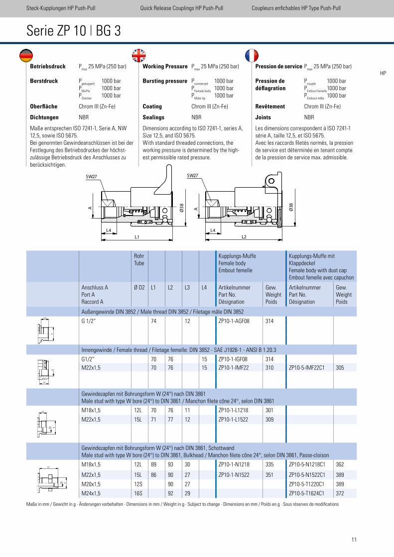
Serie ZP 10 | BG 3
RohrTube
Kupplungs-MuffeFemale bodyEmbout femelle
Kupplungs-Muffe mitKlappdeckelFemale body with dust capEmbout femelle avec capuchon
Anschluss APort ARaccord A
Ø D2 L1 L2 L3 L4 ArtikelnummerPart No.Désignation
Gew.WeightPoids
ArtikelnummerPart No.Désignation
Gew.WeightPoids
Außengewinde DIN 3852 / Male thread DIN 3852 / Filetage mâle DIN 3852
G 1/2“ 74 12 ZP10-1-AGF08 314
Innengewinde / Female thread / Filetage femelle: DIN 3852 - SAE J1926-1 - ANSI B 1.20.3
G1/2“ 70 76 15 ZP10-1-IGF08 314
M22x1,5 70 76 15 ZP10-1-IMF22 310 ZP10-5-IMF22C1 305
Gewindezapfen mit Bohrungsform W (24°) nach DIN 3861Male stud with type W bore (24°) to DIN 3861 / Manchon ilete cône 24°, selon DIN 3861
M18x1,5 12L 70 76 11 ZP10-1-L1218 301
M22x1,5 15L 71 77 12 ZP10-1-L1522 309
Gewindezapfen mit Bohrungsform W (24°) nach DIN 3861, SchottwandMale stud with type W bore (24°) to DIN 3861, Bulkhead / Manchon ilete cône 24°, selon DIN 3861, Passe-cloison
M18x1,5 12L 89 93 30 ZP10-1-N1218 335 ZP10-5-N1218C1 362
M22x1,5 15L 86 90 27 ZP10-1-N1522 351 ZP10-5-N1522C1 389
M20x1,5 12S 90 27 ZP10-5-T1220C1 389
M24x1,5 16S 92 29 ZP10-5-T1624C1 372
Maße in mm / Gewicht in g · Änderungen vorbehalten · Dimensions in mm / Weight in g · Subject to change · Dimensions en mm / Poids en g · Sous réserves de modiications
Steck-Kupplungen HP Push-Pull Quick Release Couplings HP Push-Pull Coupleurs enichables HP Type Push-Pull
HP
A
L3
L4
A
L3
SW27SW27
A
L1
Ø3
8� A
L
L4
2
L4
Ø3
8�
12
Betriebsdruck Pmax
25 MPa (250 bar)
Berstdruck Pgekuppelt
1000 bar P
Muffe 1000 bar
PStecker
1000 bar
Oberfläche Chrom III (Zn-Fe)
Dichtungen NBR
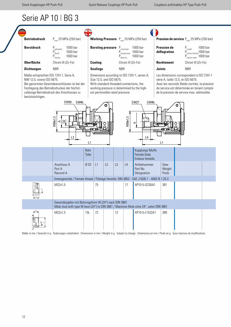
Maße entsprechen ISO 7241-1, Serie A,NW 12,5, sowie ISO 5675. Bei genormten Gewindeanschlüssen ist bei der Festlegung des Betriebsdruckes der höchst-zulässige Betriebsdruck des Anschlusses zu berücksichtigen.
Working Pressure Pmax
25 MPa (250 bar)
Bursting pressure Pconnected
1000 bar P
Female body 1000 bar
PMale tip
1000 bar
Coating Chrom III (Zn-Fe)
Sealings NBR
Dimensions according to ISO 7241-1, series A, Size 12,5, and ISO 5675.With standard threaded connections, the working pressure is determined by the high-est permissible rated pressure.
Pression de service Pmax
25 MPa (250 bar)
Pression de Pcouplé
1000 bardéflagration P
Embout femelle 1000 bar
PEmbout mâle
1000 bar
Revêtement Chrom III (Zn-Fe)
Joints NBR
Les dimensions correspondent à ISO 7241-1 série A, taille 12,5, et ISO 5675.Avec les raccords iletés normés, la pression de service est déterminée en tenant compte de la pression de service max. admissible.
Serie AP 10 | BG 3
RohrTube
Kupplungs-MuffeFemale bodyEmbout femelle
Anschluss APort ARaccord A
Ø D2 L1 L2 L3 L4 ArtikelnummerPart No.Désignation
Gew.WeightPoids
Innengewinde / Female thread / Filetage femelle: DIN 3852 - SAE J1926-1 - ANSI B 1.20.3
M22x1,5 75 17 AP10-5-I2230A1 381
Gewindezapfen mit Bohrungsform W (24°) nach DIN 3861 Male stud with type W bore (24°) to DIN 3861 / Manchon ilete cône 24°, selon DIN 3861
M22x1,5 15L 72 12 AP10-5-L1522A1 389
Maße in mm / Gewicht in g · Änderungen vorbehalten · Dimensions in mm / Weight in g · Subject to change · Dimensions en mm / Poids en g · Sous réserves de modiications
Steck-Kupplungen HP Push-Pull Quick Release Couplings HP Push-Pull Coupleurs enichables HP Type Push-Pull
L4
A
L3
SW30 SW46 SW27 SW46
D2A
38
Mx1
,5
L3 L4
L1 L1
A38
Mx1
,5
13
RohrTube
Kupplungs-MuffeFemale bodyEmbout femelle
Kupplungs-SteckerMale tipEmbout mâle
Anschluss APort ARaccord A
Ø D2 L1 L2 L3 L4 ArtikelnummerPart No.Désignation
Gew.WeightPoids
ArtikelnummerPart No.Désignation
Gew.WeightPoids
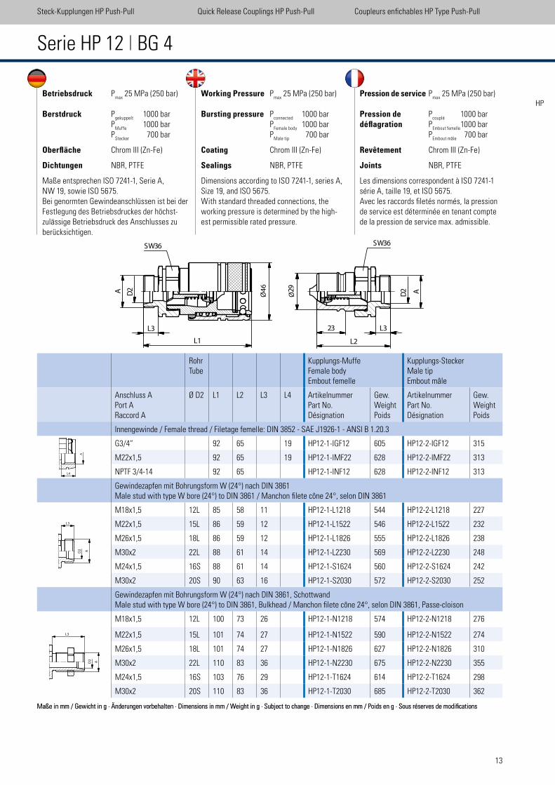
Innengewinde / Female thread / Filetage femelle: DIN 3852 - SAE J1926-1 - ANSI B 1.20.3
G3/4“ 92 65 19 HP12-1-IGF12 605 HP12-2-IGF12 315
M22x1,5 92 65 19 HP12-1-IMF22 628 HP12-2-IMF22 313
NPTF 3/4-14 92 65 HP12-1-INF12 628 HP12-2-INF12 313
Gewindezapfen mit Bohrungsform W (24°) nach DIN 3861Male stud with type W bore (24°) to DIN 3861 / Manchon ilete cône 24°, selon DIN 3861
M18x1,5 12L 85 58 11 HP12-1-L1218 544 HP12-2-L1218 227
M22x1,5 15L 86 59 12 HP12-1-L1522 546 HP12-2-L1522 232
M26x1,5 18L 86 59 12 HP12-1-L1826 555 HP12-2-L1826 238
M30x2 22L 88 61 14 HP12-1-L2230 569 HP12-2-L2230 248
M24x1,5 16S 88 61 14 HP12-1-S1624 560 HP12-2-S1624 242
M30x2 20S 90 63 16 HP12-1-S2030 572 HP12-2-S2030 252
Gewindezapfen mit Bohrungsform W (24°) nach DIN 3861, SchottwandMale stud with type W bore (24°) to DIN 3861, Bulkhead / Manchon ilete cône 24°, selon DIN 3861, Passe-cloison
M18x1,5 12L 100 73 26 HP12-1-N1218 574 HP12-2-N1218 276
M22x1,5 15L 101 74 27 HP12-1-N1522 590 HP12-2-N1522 274
M26x1,5 18L 101 74 27 HP12-1-N1826 627 HP12-2-N1826 310
M30x2 22L 110 83 36 HP12-1-N2230 675 HP12-2-N2230 355
M24x1,5 16S 103 76 29 HP12-1-T1624 614 HP12-2-T1624 298
M30x2 20S 110 83 36 HP12-1-T2030 685 HP12-2-T2030 362
Maße in mm / Gewicht in g · Änderungen vorbehalten · Dimensions in mm / Weight in g · Subject to change · Dimensions en mm / Poids en g · Sous réserves de modiications
Betriebsdruck Pmax
25 MPa (250 bar)
Berstdruck Pgekuppelt
1000 bar P
Muffe 1000 bar
PStecker
700 bar
Oberfläche Chrom III (Zn-Fe)
Dichtungen NBR, PTFE
Maße entsprechen ISO 7241-1, Serie A, NW 19, sowie ISO 5675. Bei genormten Gewindeanschlüssen ist bei der Festlegung des Betriebsdruckes der höchst-zulässige Betriebsdruck des Anschlusses zu berücksichtigen.
Working Pressure Pmax
25 MPa (250 bar)
Bursting pressure Pconnected
1000 bar P
Female body 1000 bar
PMale tip
700 bar
Coating Chrom III (Zn-Fe)
Sealings NBR, PTFE
Dimensions according to ISO 7241-1, series A, Size 19, and ISO 5675.With standard threaded connections, the working pressure is determined by the high-est permissible rated pressure.
Pression de service Pmax
25 MPa (250 bar)
Pression de Pcouplé
1000 bardéflagration P
Embout femelle 1000 bar
PEmbout mâle
700 bar
Revêtement Chrom III (Zn-Fe)
Joints NBR, PTFE
Les dimensions correspondent à ISO 7241-1 série A, taille 19, et ISO 5675. Avec les raccords iletés normés, la pression de service est déterminée en tenant compte de la pression de service max. admissible.
Serie HP 12 | BG 4
Maße in mm / Gewicht in g · Änderungen vorbehalten · Dimensions in mm / Weight in g · Subject to change · Dimensions en mm / Poids en g · Sous réserves de modiications
Steck-Kupplungen HP Push-Pull Quick Release Couplings HP Push-Pull Coupleurs enichables HP Type Push-Pull
HP
L1
L3
�
A D2
SW36
29
�
23
AD2
L3
L2
SW36
64
Ø Ø
L4
A
L3
14
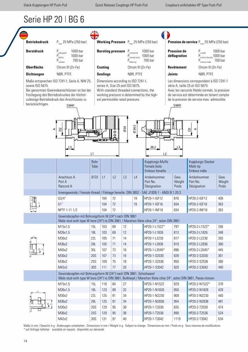
Betriebsdruck Pmax
25 MPa (250 bar)
Berstdruck Pgekuppelt
1000 bar P
Muffe 1000 bar
PStecker
700 bar
Oberfläche Chrom III (Zn-Fe)
Dichtungen NBR, PTFE
Maße entsprechen ISO 7241-1, Serie A, NW 25, sowie ISO 5675. Bei genormten Gewindeanschlüssen ist bei der Festlegung des Betriebsdruckes der höchst-zulässige Betriebsdruck des Anschlusses zu berücksichtigen.
Working Pressure Pmax
25 MPa (250 bar)
Bursting pressure Pconnected
1000 bar P
Female body 1000 bar
PMale tip
700 bar
Coating Chrom III (Zn-Fe)
Sealings NBR, PTFE
Dimensions according to ISO 7241-1,series A, Size 25 and ISO 5675.With standard threaded connections, the working pressure is determined by the high-est permissible rated pressure.
Pression de service Pmax
25 MPa (250 bar)
Pression de Pcouplé
1000 bardéflagration P
Embout femelle 1000 bar
PEmbout mâle
700 bar
Revêtement Chrom III (Zn-Fe)
Joints NBR, PTFE
Les dimensions correspondent à ISO 7241-1 série A, taille 25 et ISO 5675.Avec les raccords iletés normés, la pression de service est déterminée en tenant compte de la pression de service max. admissible.
Serie HP 20 | BG 6
RohrTube
Kupplungs-MuffeFemale bodyEmbout femelle
Kupplungs-SteckerMale tipEmbout mâle
Anschluss APort ARaccord A
Ø D2 L1 L2 L3 L4 ArtikelnummerPart No.Désignation
Gew.WeightPoids
ArtikelnummerPart No.Désignation
Gew.WeightPoids
Innengewinde / Female thread / Filetage femelle: DIN 3852 - SAE J1926-1 - ANSI B 1.20.3
G3/4“ 104 72 19 HP20-1-IGF12 876 HP20-2-IGF12 409
G1“ 104 72 19 HP20-1-IGF16 834 HP20-2-IGF16 363
NPTF 1-11 1/2 104 72 HP20-1-INF16 834 HP20-2-INF16 363
Gewindezapfen mit Bohrungsform W (24°) nach DIN 3861Male stud with type W bore (24°) to DIN 3861 / Manchon ilete cône 24°, selon DIN 3861
M15x1,5 15L 103 69 12 HP20-1-L1522* 797 HP20-2-L1522* 346
M26x1,5 18L 103 69 12 HP20-1-L1826 813 HP20-2-L1826 348
M30x2 22L 105 71 14 HP20-1-L2230 817 HP20-2-L2230 355
M36x2 28L 105 71 14 HP20-1-L2836 819 HP20-2-L2836 360
M45x2 35L 107 73 16 HP20-1-L3545* 896 HP20-2-L3545* 445
M30x2 20S 107 73 16 HP20-1-S2030 828 HP20-2-S2030 361
M36x2 25S 109 75 18 HP20-1-S2536 850 HP20-2-S2536 380
M42x2 30S 111 77 20 HP20-1-S3042 920 HP20-2-S3042 440
Gewindezapfen mit Bohrungsform W (24°) nach DIN 3861, SchottwandMale stud with type W bore (24°) to DIN 3861, Bulkhead / Manchon ilete cône 24°, selon DIN 3861, Passe-cloison
M15x1,5 15L 118 84 27 HP20-1-N1522 829 HP20-2-N1522* 378
M26x1,5 18L 123 89 32 HP20-1-N1826 850 HP20-2-N1826 428
M30x2 22L 125 91 34 HP20-1-N2230 909 HP20-2-N2230 440
M36x2 28L 125 91 34 HP20-1-N2836 954 HP20-2-N2836 481
M30x2 20S 129 95 38 HP20-1-T2030 835 HP20-2-T2030 474
M36x2 25S 129 95 38 HP20-1-T2536 890 HP20-2-T2536 524
M42x2 30S 131 97 40 HP20-1-T3042 1119 HP20-2-T3042 634
Maße in mm / Gewicht in g · Änderungen vorbehalten · Dimensions in mm / Weight in g · Subject to change · Dimensions en mm / Poids en g · Sous réserves de modiications* auf Anfrage lieferbar · available on request · disponible sur demande
Steck-Kupplungen HP Push-Pull Quick Release Couplings HP Push-Pull Coupleurs enichables HP Type Push-Pull
A D2
L3
L1
54
�
SW41
34
.5�
28.2
L2
L3
A
D2
SW41
Ø Ø
L4
A
L3
15
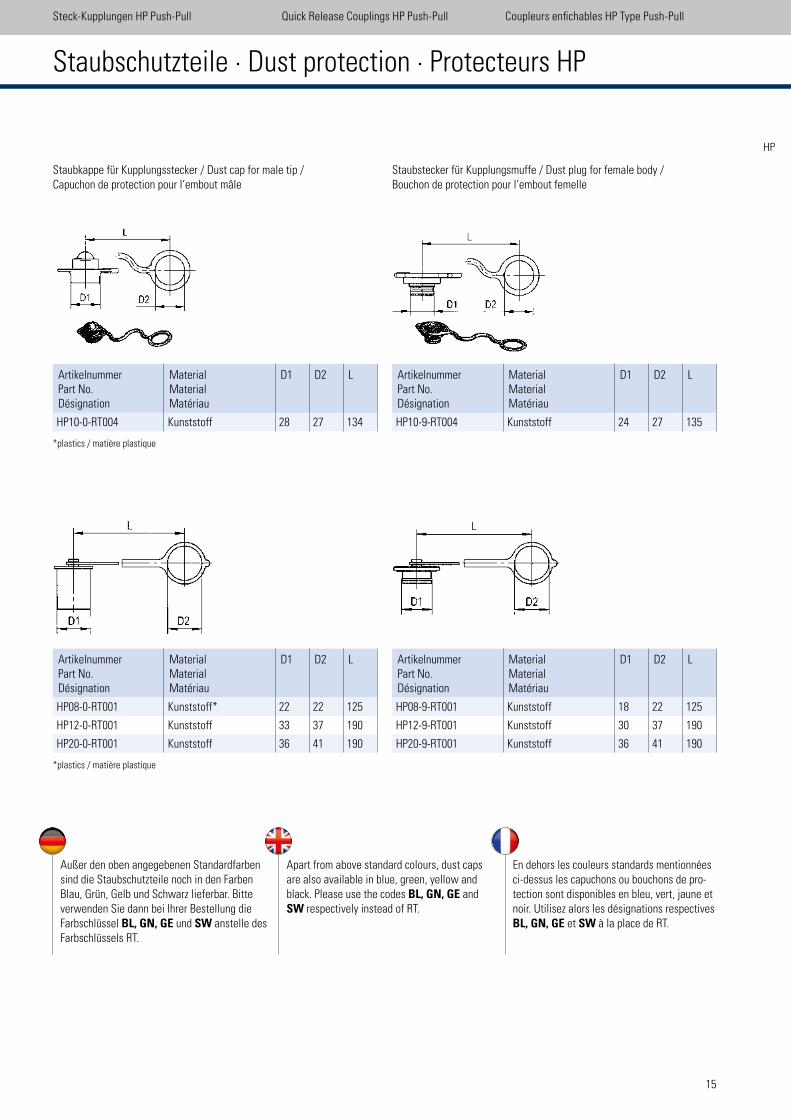
Staubschutzteile · Dust protection · Protecteurs HP
Staubkappe für Kupplungsstecker / Dust cap for male tip /Capuchon de protection pour l‘embout mâle
ArtikelnummerPart No.Désignation
MaterialMaterialMatériau
D1 D2 L
HP10-0-RT004 Kunststoff 28 27 134
ArtikelnummerPart No.Désignation
MaterialMaterialMatériau
D1 D2 L
HP08-0-RT001 Kunststoff* 22 22 125
HP12-0-RT001 Kunststoff 33 37 190
HP20-0-RT001 Kunststoff 36 41 190
Staubstecker für Kupplungsmuffe / Dust plug for female body /Bouchon de protection pour l‘embout femelle
ArtikelnummerPart No.Désignation
MaterialMaterialMatériau
D1 D2 L
HP10-9-RT004 Kunststoff 24 27 135
ArtikelnummerPart No.Désignation
MaterialMaterialMatériau
D1 D2 L
HP08-9-RT001 Kunststoff 18 22 125
HP12-9-RT001 Kunststoff 30 37 190
HP20-9-RT001 Kunststoff 36 41 190
*plastics / matière plastique
*plastics / matière plastique
Steck-Kupplungen HP Push-Pull Quick Release Couplings HP Push-Pull Coupleurs enichables HP Type Push-Pull
Außer den oben angegebenen Standardfarben sind die Staubschutzteile noch in den Farben Blau, Grün, Gelb und Schwarz lieferbar. Bitte verwenden Sie dann bei Ihrer Bestellung die Farbschlüssel BL, GN, GE und SW anstelle des Farbschlüssels RT.
Apart from above standard colours, dust caps are also available in blue, green, yellow and black. Please use the codes BL, GN, GE and SW respectively instead of RT.
En dehors les couleurs standards mentionnées ci-dessus les capuchons ou bouchons de pro-tection sont disponibles en bleu, vert, jaune et noir. Utilisez alors les désignations respectives BL, GN, GE et SW à la place de RT.
HP

17
FH 19 / BG 6 28
FU 19 / BG 6 - UDK 29
FH 25 / BG 8 30
FX 32 / BG 10 31
Staubschutzteile / Dust protection / Protecteurs 32
Serie FH/FUSerie FH/FU / Series FH/FU /
Série FH/FU 19
FH 06 / BG 1 22
FH 10 / BG 2 23
FU 10 / BG 2 - UDK 24
FH 12 / BG 3 25
FU 12 / BG 3 - UDK 26
FH 16 / BG 4 27
Steck-Kupplungen FH lachdichtend Quick Release Couplings FH Flat Face Coupleurs enichables FH Type à face plane
FHFU
18
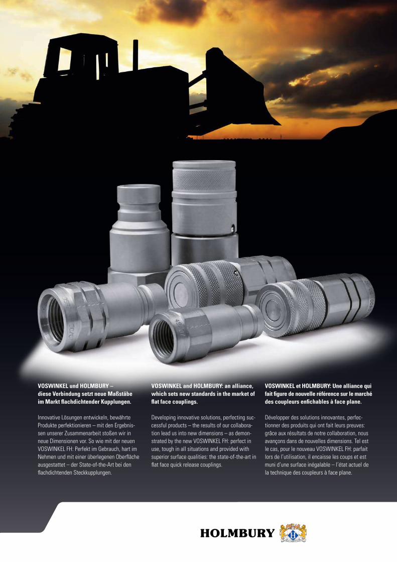
VOSWINKEL und HOLMBURY –
diese Verbindung setzt neue Maßstäbe
im Markt flachdichtender Kupplungen.
Innovative Lösungen entwickeln, bewährte Produkte perfektionieren – mit den Ergebnis- sen unserer Zusammenarbeit stoßen wir in neue Dimensionen vor. So wie mit der neuen VOSWINKEL FH: Perfekt im Gebrauch, hart im Nehmen und mit einer überlegenen Oberläche ausgestattet – der State-of-the-Art bei den lachdichtenden Steckkupplungen.
VOSWINKEL and HOLMBURY: an alliance,
which sets new standards in the market of
flat face couplings.
Developing innovative solutions, perfecting suc-cessful products – the results of our collabora-tion lead us into new dimensions – as demon-strated by the new VOSWINKEL FH: perfect in use, tough in all situations and provided with superior surface qualities: the state-of-the-art in lat face quick release couplings.
VOSWINKEL et HOLMBURY: Une alliance qui
fait figure de nouvelle référence sur le marché
des coupleurs enfichables à face plane.
Développer des solutions innovantes, perfec-tionner des produits qui ont fait leurs preuves: grâce aux résultats de notre collaboration, nous avançons dans de nouvelles dimensions. Tel est le cas, pour le nouveau VOSWINKEL FH: parfait lors de l’utilisation, il encaisse les coups et est muni d’une surface inégalable – l’état actuel de la technique des coupleurs à face plane.
19
Steck-Kupplungen FH lachdichtend Quick Release Couplings FH Flat Face Coupleurs enichables FH Type à face plane
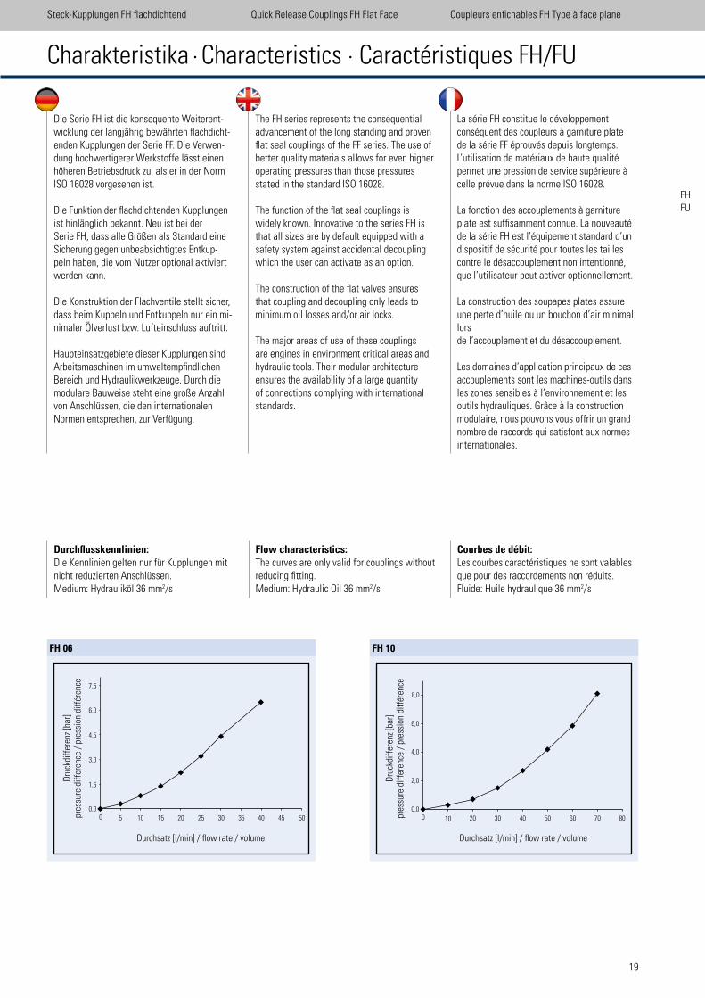
Die Serie FH ist die konsequente Weiterent-wicklung der langjährig bewährten lachdicht-enden Kupplungen der Serie FF. Die Verwen-dung hochwertigerer Werkstoffe lässt einen höheren Betriebsdruck zu, als er in der Norm ISO 16028 vorgesehen ist.
Die Funktion der lachdichtenden Kupplungen ist hinlänglich bekannt. Neu ist bei der Serie FH, dass alle Größen als Standard eine Sicherung gegen unbeabsichtigtes Entkup-peln haben, die vom Nutzer optional aktiviert werden kann.
Die Konstruktion der Flachventile stellt sicher, dass beim Kuppeln und Entkuppeln nur ein mi-nimaler Ölverlust bzw. Lufteinschluss auftritt.
Haupteinsatzgebiete dieser Kupplungen sind Arbeitsmaschinen im umweltempindlichen Bereich und Hydraulikwerkzeuge. Durch die modulare Bauweise steht eine große Anzahl von Anschlüssen, die den internationalen Normen entsprechen, zur Verfügung.
The FH series represents the consequential advancement of the long standing and proven lat seal couplings of the FF series. The use of better quality materials allows for even higher operating pressures than those pressures stated in the standard ISO 16028.
The function of the lat seal couplings is widely known. Innovative to the series FH is that all sizes are by default equipped with a safety system against accidental decoupling which the user can activate as an option.
The construction of the lat valves ensures that coupling and decoupling only leads to minimum oil losses and/or air locks.
The major areas of use of these couplings are engines in environment critical areas and hydraulic tools. Their modular architecture ensures the availability of a large quantity of connections complying with international standards.
La série FH constitue le développement conséquent des coupleurs à garniture plate de la série FF éprouvés depuis longtemps. L’utilisation de matériaux de haute qualité permet une pression de service supérieure à celle prévue dans la norme ISO 16028.
La fonction des accouplements à garniture plate est sufisamment connue. La nouveauté de la série FH est l’équipement standard d’un dispositif de sécurité pour toutes les tailles contre le désaccouplement non intentionné, que l’utilisateur peut activer optionnellement.
La construction des soupapes plates assure une perte d’huile ou un bouchon d’air minimal lors de l’accouplement et du désaccouplement.
Les domaines d’application principaux de ces accouplements sont les machines-outils dans les zones sensibles à l’environnement et les outils hydrauliques. Grâce à la construction modulaire, nous pouvons vous offrir un grand nombre de raccords qui satisfont aux normes internationales.
Charakteristika · Characteristics · Caractéristiques FH/FU
FHFU
FH 10
Durchsatz [l/min] / low rate / volume
0 100,0
2,0
4,0
6,0
8,0
20 30 40 50 60 70 80
Dru
ckdi
ffer
enz
[bar
]pr
essu
re d
iffer
ence
/ p
ress
ion
diff
éren
ce
FH 06
Durchsatz [l/min] / low rate / volume
00,0
1,5
3,0
4,5
6,0
7,5
5045403530252015105
Dru
ckdi
ffer
enz
[bar
]pr
essu
re d
iffer
ence
/ p
ress
ion
diff
éren
ce
Durchflusskennlinien: Die Kennlinien gelten nur für Kupplungen mit nicht reduzierten Anschlüssen. Medium: Hydrauliköl 36 mm2/s
Flow characteristics: The curves are only valid for couplings without reducing itting. Medium: Hydraulic Oil 36 mm2/s
Courbes de débit: Les courbes caractéristiques ne sont valables que pour des raccordements non réduits. Fluide: Huile hydraulique 36 mm2/s
20
Steck-Kupplungen FH lachdichtend Quick Release Couplings FH Flat Face Coupleurs enichables FH Type à face plane
Durchsatz [l/min] / low rate / volume
0 100,0
2,5
5,0
7,5
10,0
12,5
15,0
20 30 40 50 60 70 80 90 100 110 120 130 140 150 160
Dru
ckdi
ffer
enz
[bar
]pr
essu
re d
iffer
ence
/ p
ress
ion
diff
éren
ce
FH 12
Durchsatz [l/min] / low rate / volume
0 20 40 60 80 100 120 140 1600,0
1,0
2,0
3,0
Dru
ckdi
ffer
enz
[bar
]pr
essu
re d
iffer
ence
/ p
ress
ion
diff
éren
ce
FH 19
FH 16
Durchsatz [l/min] / low rate / volume
00,0
1,5
3,0
4,5
160 14012010080
60 80 100 120 140 1604020
Dru
ckdi
ffer
enz
[bar
]pr
essu
re d
iffer
ence
/ p
ress
ion
diff
éren
ce
Durchflusskennlinien: Die Kennlinien gelten nur für Kupplungen mit nicht reduzierten Anschlüssen. Medium: Hydrauliköl 36 mm2/s
Flow characteristics: The curves are only valid for couplings without reducing itting. Medium: Hydraulic Oil 36 mm2/s
Courbes de débit: Les courbes caractéristiques ne sont valables que pour des raccordements non réduits. Fluide: Huile hydraulique 36 mm2/s
Durchsatz [l/min] / low rate / volume
0 200,0
1,0
2,0
3,0
4,0
5,0
40 60 80 100 120 140 160 180 200 220 240 260
Dru
ckdi
ffer
enz
[bar
]pr
essu
re d
iffer
ence
/ p
ress
ion
diff
éren
ce
FH 25
Durchsatz [l/min] / low rate / volume
0 100 200 300 400 500 600 700 8000,0
11,0
Dru
ckdi
ffer
enz
[bar
]pr
essu
re d
iffer
ence
/ p
ress
ion
diff
éren
ce
FX 32
900
10,0
9,0
8,0
7,0
6,0
5,0
4,0
3,0
2,0
1,0
21
Durchsatz [l/min] / low rate / volume
0 100,0
2,0
4,0
6,0
10,0
8,0
20 30 40 50 60 70
Dru
ckdi
ffer
enz
[bar
]pr
essu
re d
iffer
ence
/ p
ress
ion
diff
éren
ce
FU 10
Durchsatz [l/min] / low rate / volume
00,0
2,0
4,0
6,0
8,0
10,0
140130120110100908070605040302010D
ruck
diff
eren
z [b
ar]
pres
sure
diff
eren
ce /
pre
ssio
n di
ffér
ence
FU 12
Durchsatz [l/min] / low rate / volume
0 1501401301201101009080706050403020100,0
1,0
2,0
4,0
3,0
Dru
ckdi
ffer
enz
[bar
]pr
essu
re d
iffer
ence
/ p
ress
ion
diff
éren
ce
FU 19
FHFU
Steck-Kupplungen FUunter Druck kuppelbar
Coupleurs enichables FUpeut ´̀etre couplé sous pression
Quick-Release Couplingsconnect under pressure
22
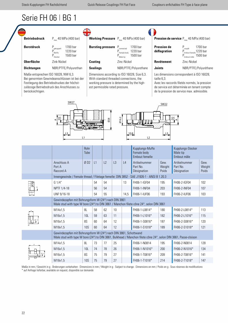
Betriebsdruck Pmax
40 MPa (400 bar)
Berstdruck Pgekuppelt
1700 bar P
Muffe 1220 bar
PStecker
1500 bar
Oberfläche Zink-Nickel
Dichtungen NBR/PTFE/Polyurethan
Maße entsprechen ISO 16028, NW 6,3.Bei genormten Gewindeanschlüssen ist bei der Festlegung des Betriebsdruckes der höchst-zulässige Betriebsdruck des Anschlusses zu berücksichtigen.
Working Pressure Pmax
40 MPa (400 bar)
Bursting pressure Pconnected
1700 bar P
Female body 1220 bar
PMale tip
1500 bar
Coating Zinc-Nickel
Sealings NBR/PTFE/Polyurethane
Dimensions according to ISO 16028, Size 6,3.With standard threaded connections, the working pressure is determined by the high-est permissible rated pressure.
Pression de service Pmax
40 MPa (400 bar)
Pression de Pcouplé
1700 bardéflagration P
Embout femelle 1220 bar
PEmbout mâle
1500 bar
Revêtement Zinc-Nickel
Joints NBR/PTFE/Polyuréthane
Les dimensions correspondent à ISO 16028, taille 6,3.Avec les raccords iletés normés, la pression de service est déterminée en tenant compte de la pression de service max. admissible.
Serie FH 06 | BG 1
RohrTube
Kupplungs-MuffeFemale bodyEmbout femelle
Kupplungs-SteckerMale tipEmbout mâle
Anschluss APort ARaccord A
Ø D2 L1 L2 L3 L4 ArtikelnummerPart No.Désignation
Gew.WeightPoids
ArtikelnummerPart No.Désignation
Gew.WeightPoids
Innengewinde / Female thread / Filetage femelle: DIN 3852 - SAE J1926-1 - ANSI B 1.20.3
G 1/4“ 54 54 13 FH06-1-IGF04 195 FH06-2-IGF04 102
NPTF 1/4-18 56 54 FH06-1-INF04 203 FH06-2-INF04 107
UNF 9/16-18 54 55 14,5 FH06-1-IUF06 193 FH06-2-IUF06 103
Gewindezapfen mit Bohrungsform W (24°) nach DIN 3861Male stud with type W bore (24°) to DIN 3861 / Manchon ilete cône 24°, selon DIN 3861
M14x1,5 8L 58 62 10 FH06-1-L0814* 180 FH06-2-L0814* 113
M16x1,5 10L 59 63 11 FH06-1-L1016* 182 FH06-2-L1016* 115
M16x1,5 8S 60 64 12 FH06-1-S0816* 187 FH06-2-S0816* 120
M18x1,5 10S 60 64 12 FH06-1-S1018* 189 FH06-2-S1018* 121
Gewindezapfen mit Bohrungsform W (24°) nach DIN 3861, SchottwandMale stud with type W bore (24°) to DIN 3861, Bulkhead / Manchon ilete cône 24°, selon DIN 3861, Passe-cloison
M14x1,5 8L 73 77 25 FH06-1-N0814 195 FH06-2-N0814 128
M16x1,5 10L 74 78 26 FH06-1-N1016* 200 FH06-2-N1016* 134
M16x1,5 8S 75 79 27 FH06-1-T0816* 209 FH06-2-T0816* 141
M18x1,5 10S 75 79 27 FH06-1-T1018* 214 FH06-2-T1018* 147
Steck-Kupplungen FH lachdichtend Quick Release Couplings FH Flat Face Coupleurs enichables FH Type à face plane
Maße in mm / Gewicht in g · Änderungen vorbehalten · Dimensions in mm / Weight in g · Subject to change · Dimensions en mm / Poids en g · Sous réserves de modiications* auf Anfrage lieferbar, available on request, disponible sur demande
D2
D2
�
L1
Ø2
8
SW27����
Ø1
6.2
AA
SW22
10.8
L2
L3L3
A
L3
L4
23
FHFU
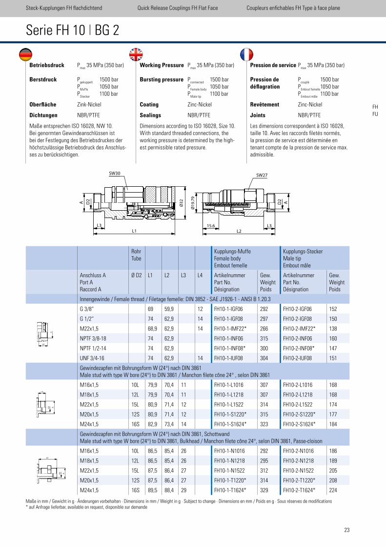
Betriebsdruck Pmax
35 MPa (350 bar)
Berstdruck Pgekuppelt
1500 bar P
Muffe 1050 bar
PStecker
1100 bar
Oberfläche Zink-Nickel
Dichtungen NBR/PTFE
Maße entsprechen ISO 16028, NW 10.Bei genormten Gewindeanschlüssen ist bei der Festlegung des Betriebsdruckes der höchstzulässige Betriebsdruck des Anschlus-ses zu berücksichtigen.
Working Pressure Pmax
35 MPa (350 bar)
Bursting pressure Pconnected
1500 bar P
Female body 1050 bar
PMale tip
1100 bar
Coating Zinc-Nickel
Sealings NBR/PTFE
Dimensions according to ISO 16028, Size 10.With standard threaded connections, the working pressure is determined by the high-est permissible rated pressure.
Pression de service Pmax
35 MPa (350 bar)
Pression de Pcouplé
1500 bardéflagration P
Embout femelle 1050 bar
PEmbout mâle
1100 bar
Revêtement Zinc-Nickel
Joints NBR/PTFE
Les dimensions correspondent à ISO 16028, taille 10. Avec les raccords iletés normés, la pression de service est déterminée en tenant compte de la pression de service max. admissible.
Serie FH 10 | BG 2
RohrTube
Kupplungs-MuffeFemale bodyEmbout femelle
Kupplungs-SteckerMale tipEmbout mâle
Anschluss APort ARaccord A
Ø D2 L1 L2 L3 L4 ArtikelnummerPart No.Désignation
Gew.WeightPoids
ArtikelnummerPart No.Désignation
Gew.WeightPoids
Innengewinde / Female thread / Filetage femelle: DIN 3852 - SAE J1926-1 - ANSI B 1.20.3
G 3/8“ 69 59,9 12 FH10-1-IGF06 292 FH10-2-IGF06 152
G 1/2“ 74 62,9 14 FH10-1-IGF08 297 FH10-2-IGF08 150
M22x1,5 68,9 62,9 14 FH10-1-IMF22* 266 FH10-2-IMF22* 138
NPTF 3/8-18 74 62,9 FH10-1-INF06 315 FH10-2-INF06 160
NPTF 1/2-14 74 62,9 FH10-1-INF08* 300 FH10-2-INF08* 147
UNF 3/4-16 74 62,9 14 FH10-1-IUF08 304 FH10-2-IUF08 151
Gewindezapfen mit Bohrungsform W (24°) nach DIN 3861Male stud with type W bore (24°) to DIN 3861 / Manchon ilete cône 24° , selon DIN 3861
M16x1,5 10L 79,9 70,4 11 FH10-1-L1016 307 FH10-2-L1016 168
M18x1,5 12L 79,9 70,4 11 FH10-1-L1218 307 FH10-2-L1218 168
M22x1,5 15L 80,9 71,4 12 FH10-1-L1522 314 FH10-2-L1522 174
M20x1,5 12S 80,9 71,4 12 FH10-1-S1220* 315 FH10-2-S1220* 177
M24x1,5 16S 82,9 73,4 14 FH10-1-S1624* 323 FH10-2-S1624* 184
Gewindezapfen mit Bohrungsform W (24°) nach DIN 3861, SchottwandMale stud with type W bore (24°) to DIN 3861, Bulkhead / Manchon ilete cône 24°, selon DIN 3861, Passe-cloison
M16x1,5 10L 86,5 85,4 26 FH10-1-N1016 292 FH10-2-N1016 186
M18x1,5 12L 86,5 85,4 26 FH10-1-N1218 295 FH10-2-N1218 189
M22x1,5 15L 87,5 86,4 27 FH10-1-N1522 312 FH10-2-N1522 205
M20x1,5 12S 87,5 86,4 27 FH10-1-T1220* 314 FH10-2-T1220* 208
M24x1,5 16S 89,5 88,4 29 FH10-1-T1624* 329 FH10-2-T1624* 224
Steck-Kupplungen FH lachdichtend Quick Release Couplings FH Flat Face Coupleurs enichables FH Type à face plane
Maße in mm / Gewicht in g · Änderungen vorbehalten · Dimensions in mm / Weight in g · Subject to change · Dimensions en mm / Poids en g · Sous réserves de modiications* auf Anfrage lieferbar, available on request, disponible sur demande
D2
A�
L3
L1
SW30
15.6
L2
Ø1
9.7
9
Ø3
2
D2
A
SW27
L3
A
L3
L4
24
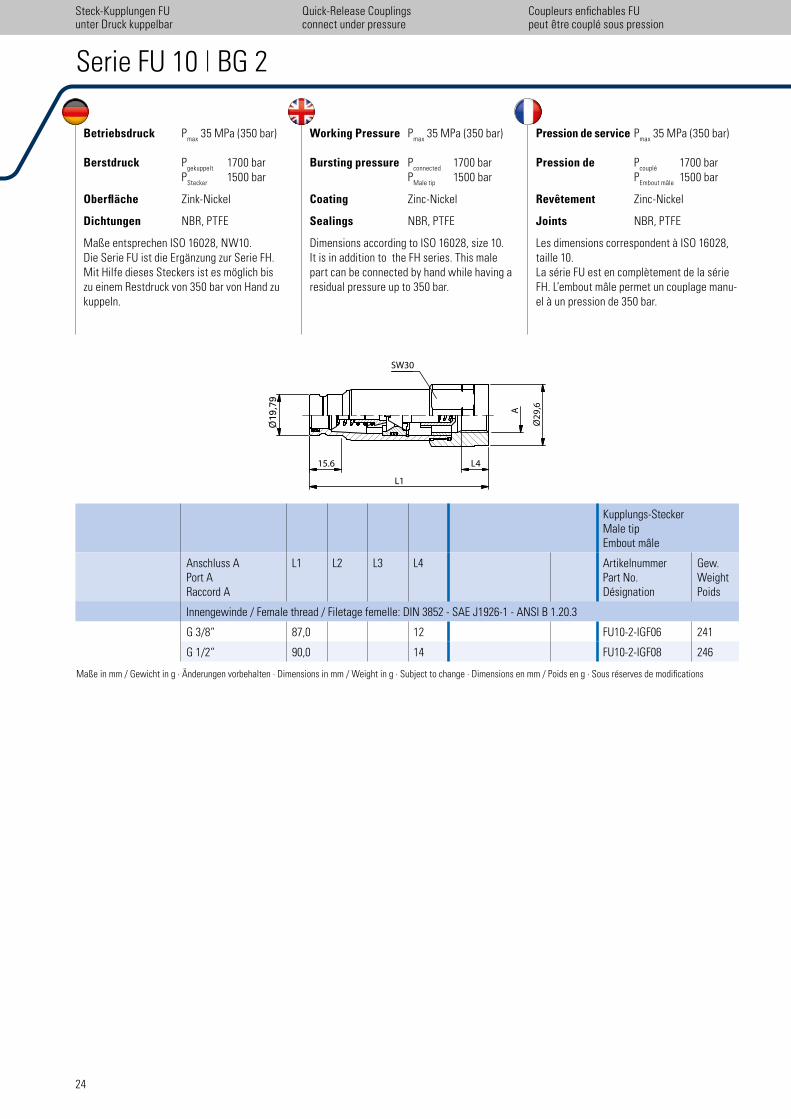
Betriebsdruck Pmax
35 MPa (350 bar)
Berstdruck Pgekuppelt
1700 bar P
Stecker 1500 bar
Oberfläche Zink-Nickel
Dichtungen NBR, PTFE
Maße entsprechen ISO 16028, NW10. Die Serie FU ist die Ergänzung zur Serie FH. Mit Hilfe dieses Steckers ist es möglich bis zu einem Restdruck von 350 bar von Hand zu kuppeln.
Working Pressure Pmax
35 MPa (350 bar)
Bursting pressure Pconnected
1700 bar P
Male tip 1500 bar
Coating Zinc-Nickel
Sealings NBR, PTFE
Dimensions according to ISO 16028, size 10. It is in addition to the FH series. This male part can be connected by hand while having a residual pressure up to 350 bar.
Pression de service Pmax
35 MPa (350 bar)
Pression de Pcouplé
1700 bar P
Embout mâle 1500 bar
Revêtement Zinc-Nickel
Joints NBR, PTFE
Les dimensions correspondent à ISO 16028, taille 10. La série FU est en complètement de la série FH. L’embout mâle permet un couplage manu-el à un pression de 350 bar.
Serie FU 10 | BG 2
Kupplungs-SteckerMale tipEmbout mâle
Anschluss APort ARaccord A
L1 L2 L3 L4 ArtikelnummerPart No.Désignation
Gew.WeightPoids
Innengewinde / Female thread / Filetage femelle: DIN 3852 - SAE J1926-1 - ANSI B 1.20.3
G 3/8“ 87,0 12 FU10-2-IGF06 241
G 1/2“ 90,0 14 FU10-2-IGF08 246
Maße in mm / Gewicht in g · Änderungen vorbehalten · Dimensions in mm / Weight in g · Subject to change · Dimensions en mm / Poids en g · Sous réserves de modiications
Steck-Kupplungen FUunter Druck kuppelbar
Coupleurs enichables FUpeut ´̀etre couplé sous pression
Quick-Release Couplingsconnect under pressure
����
�Ø
19,7
9
15.6��� L4
L1�
����
Ø2
9,6
SW30���
A�
UDK-Connect
under
Pressure
25
FHFU
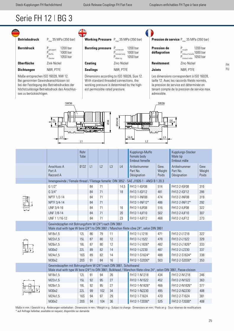
Serie FH 12 | BG 3
RohrTube
Kupplungs-MuffeFemale bodyEmbout femelle
Kupplungs-SteckerMale tipEmbout mâle
Anschluss APort ARaccord A
Ø D2 L1 L2 L3 L4 ArtikelnummerPart No.Désignation
Gew.WeightPoids
ArtikelnummerPart No.Désignation
Gew.WeightPoids
Innengewinde / Female thread / Filetage femelle: DIN 3852 - SAE J1926-1 - ANSI B 1.20.3
G 1/2“ 84 71 14,5 FH12-1-IGF08 514 FH12-2-IGF08 316
G 3/4“ 84 71 18 FH12-1-IGF12 481 FH12-2-IGF12 286
NPTF 1/2-14 84 71 FH12-1-INF08 474 FH12-2-INF08 319
NPTF 3/4-14 84 71 FH12-1-INF12* 486 FH12-2-INF12* 292
UNF 3/4-16 84 71 16 FH12-1-IUF08 516 FH12-2-IUF08 322
UNF 7/8-14 84 71 20 FH12-1-IUF10 502 FH12-2-IUF10 307
UNF 1 1/16-12 84 71 23 FH12-1-IUF12 468 FH12-2-IUF12 273
Gewindezapfen mit Bohrungsform W (24°) nach DIN 3861Male stud with type W bore (24°) to DIN 3861 / Manchon ilete cône 24°, selon DIN 3861
M18x1,5 12L 86 79 11 FH12-1-L1218 471 FH12-2-L1218 322
M22x1,5 15L 87 80 12 FH12-1-L1522 478 FH12-2-L1522 329
M26x1,5 18L 87 80 12 FH12-1-L1826* 482 FH12-2-L1826* 333
M30x2 22L 89 82 14 FH12-1-L2230 487 FH12-2-L2230 337
M24x1,5 16S 89 82 14 FH12-1-S1624* 488 FH12-2-S1624* 338
M30x2 20S 91 84 16 FH12-1-S2030* 503 FH12-2-S2030* 353
Gewindezapfen mit Bohrungsform W (24°) nach DIN 3861, SchottwandMale stud with type W bore (24°) to DIN 3861, Bulkhead / Manchon ilete cône 24°, selon DIN 3861, Passe-cloison
M18x1,5 12L 91 94 26 FH12-1-N1218 434 FH12-2-N1218 346
M22x1,5 15L 92 95 27 FH12-1-N1522 452 FH12-2-N1522 363
M26x1,5 18L 92 95 27 FH12-1-N1826* 466 FH12-2-N1826* 377
M30x2 22L 99 102 34 FH12-1-N2230 495 FH12-2-N2230 406
M24x1,5 16S 94 97 29 FH12-1-T1624 470 FH12-2-T1624 381
M30x2 20S 94 104 36 FH12-1-T2030* 525 FH12-2-T2030* 408
Betriebsdruck Pmax
35 MPa (350 bar)
Berstdruck Pgekuppelt
1200 bar P
Muffe 1000 bar
PStecker
1050 bar
Oberfläche Zink-Nickel
Dichtungen NBR, PTFE
Maße entsprechen ISO 16028, NW 12.Bei genormten Gewindeanschlüssen ist bei der Festlegung des Betriebsdruckes der höchstzulässige Betriebsdruck des Anschlus-ses zu berücksichtigen.
Working Pressure Pmax
35 MPa (350 bar)
Bursting pressure Pconnected
1200 bar P
Female body 1000 bar
PMale tip
1050 bar
Coating Zinc-Nickel
Sealings NBR, PTFE
Dimensions according to ISO 16028, Size 12.With standard threaded connections, the working pressure is determined by the high-est permissible rated pressure.
Pression de service Pmax
35 MPa (350 bar)
Pression de Pcouplé
1200 bardéflagration P
Embout femelle 1000 bar
PEmbout mâle
1050 bar
Revêtement Zinc-Nickel
Joints NBR, PTFE
Les dimensions correspondent à ISO 16028, taille 12. Avec les raccords iletés normés, la pression de service est déterminée en tenant compte de la pression de service max. admissible.
Steck-Kupplungen FH lachdichtend Quick Release Couplings FH Flat Face Coupleurs enichables FH Type à face plane
Maße in mm / Gewicht in g · Änderungen vorbehalten · Dimensions in mm / Weight in g · Subject to change · Dimensions en mm / Poids en g · Sous réserves de modiications* auf Anfrage lieferbar, available on request, disponible sur demande
�D
2
A
L3
L1�
��
Ø3
8
SW36�
Ø2
4.5
8���
��
L3
L2�
16.9
SW36���
��
AD2
A
L3
L4
26
Serie FU 12 | BG 3
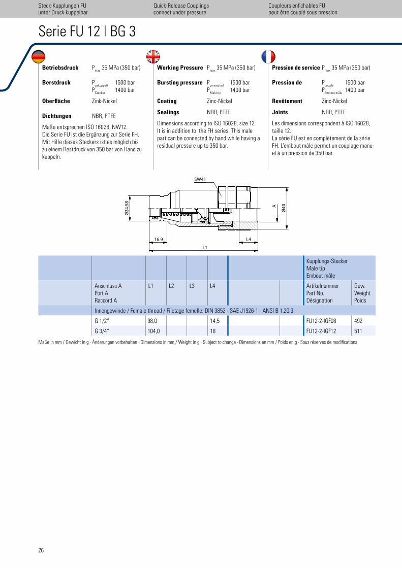
Betriebsdruck Pmax
35 MPa (350 bar)
Berstdruck Pgekuppelt
1500 bar P
Stecker 1400 bar
Oberfläche Zink-Nickel
Dichtungen NBR, PTFE
Maße entsprechen ISO 16028, NW12. Die Serie FU ist die Ergänzung zur Serie FH. Mit Hilfe dieses Steckers ist es möglich bis zu einem Restdruck von 350 bar von Hand zu kuppeln.
Working Pressure Pmax
35 MPa (350 bar)
Bursting pressure Pconnected
1500 bar P
Male tip 1400 bar
Coating Zinc-Nickel
Sealings NBR, PTFE
Dimensions according to ISO 16028, size 12. It is in addition to the FH series. This male part can be connected by hand while having a residual pressure up to 350 bar.
Pression de service Pmax
35 MPa (350 bar)
Pression de Pcouplé
1500 bar P
Embout mâle 1400 bar
Revêtement Zinc-Nickel
Joints NBR, PTFE
Les dimensions correspondent à ISO 16028, taille 12. La série FU est en complètement de la série FH. L‘embout mâle permet un couplage manu-el à un pression de 350 bar.
Kupplungs-SteckerMale tipEmbout mâle
Anschluss APort ARaccord A
L1 L2 L3 L4 ArtikelnummerPart No.Désignation
Gew.WeightPoids
Innengewinde / Female thread / Filetage femelle: DIN 3852 - SAE J1926-1 - ANSI B 1.20.3
G 1/2“ 98,0 14,5 FU12-2-IGF08 492
G 3/4“ 104,0 18 FU12-2-IGF12 511
Maße in mm / Gewicht in g · Änderungen vorbehalten · Dimensions in mm / Weight in g · Subject to change · Dimensions en mm / Poids en g · Sous réserves de modiications
Steck-Kupplungen FUunter Druck kuppelbar
Coupleurs enichables FUpeut ´̀etre couplé sous pression
Quick-Release Couplingsconnect under pressure
�L1�
A ��
Ø4
0�
16.9�� L4
Ø2
4.5
8�
��
�
SW41���
UDK-Connect
under
Pressure
27
FHFU
Betriebsdruck Pmax
35 MPa (350 bar)
Berstdruck Pgekuppelt
1200 bar P
Muffe 1100 bar
PStecker
1100 bar
Oberfläche Zink-Nickel
Dichtungen NBR, PTFE, Polyurethan
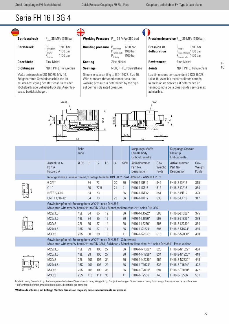
Maße entsprechen ISO 16028, NW 16.Bei genormten Gewindeanschlüssen ist bei der Festlegung des Betriebsdruckes der höchstzulässige Betriebsdruck des Anschlus-ses zu berücksichtigen.
Working Pressure Pmax
35 MPa (350 bar)
Bursting pressure Pconnected
1200 bar P
Female body 1100 bar
PMale tip
1100 bar
Coating Zinc-Nickel
Sealings NBR, PTFE, Polyurethane
Dimensions according to ISO 16028, Size 16.With standard threaded connections, the working pressure is determined by the high-est permissible rated pressure.
Pression de service Pmax
35 MPa (350 bar)
Pression de Pcouplé
1200 bardéflagration P
Embout femelle 1100 bar
PEmbout mâle
1100 bar
Revêtement Zinc-Nickel
Joints NBR, PTFE, Polyuréthane
Les dimensions correspondent à ISO 16028, taille 16. Avec les raccords iletés normés, la pression de service est déterminée en tenant compte de la pression de service max. admissible.
Serie FH 16 | BG 4
RohrTube
Kupplungs-MuffeFemale bodyEmbout femelle
Kupplungs-SteckerMale tipEmbout mâle
Anschluss APort ARaccord A
Ø D2 L1 L2 L3 L4 SW1 ArtikelnummerPart No.Désignation
Gew.WeightPoids
ArtikelnummerPart No.Désignation
Gew.WeightPoids
Innengewinde / Female thread / Filetage femelle: DIN 3852 - SAE J1926-1 - ANSI B 1.20.3
G 3/4“ 84 73 20 36 FH16-1-IGF12 646 FH16-2-IGF12 315
G 1“ 86 77,5 21 41 FH16-1-IGF16 612 FH16-2-IGF16 364
NPTF 3/4-16 84 73 36 FH16-1-INF12 651 FH16-2-INF12 323
UNF 1 1/16-12 84 73 23 36 FH16-1-IUF12 633 FH16-2-IUF12 317
Gewindezapfen mit Bohrungsform W (24°) nach DIN 3861Male stud with type W bore (24°) to DIN 3861 / Manchon ilete cône 24°, selon DIN 3861
M22x1,5 15L 84 85 12 36 FH16-1-L1522* 588 FH16-2-L1522* 375
M26x1,5 18L 84 85 12 36 FH16-1-L1826* 592 FH16-2-L1826* 379
M30x2 22L 86 87 14 36 FH16-1-L2230* 597 FH16-2-L2230* 384
M24x1,5 16S 86 87 14 36 FH16-1-S1624* 597 FH16-2-S1624* 385
M30x2 20S 88 89 16 41 FH16-1-S2030* 613 FH16-2-S2030* 400
Gewindezapfen mit Bohrungsform W (24°) nach DIN 3861, SchottwandMale stud with type W bore (24°) to DIN 3861, Bulkhead / Manchon ilete cône 24°, selon DIN 3861, Passe-cloison
M22x1,5 15L 99 100 27 36 FH16-1-N1522* 620 FH16-2-N1522* 404
M26x1,5 18L 99 100 27 36 FH16-1-N1826* 634 FH16-2-N1826* 418
M30x2 22L 106 107 34 36 FH16-1-N2230* 664 FH16-2-N2230* 448
M24x1,5 16S 101 102 29 36 FH16-1-T1624* 638 FH16-2-T1624* 422
M30x2 20S 108 109 36 36 FH16-1-T2030* 694 FH16-2-T2030* 477
M36x2 25S 110 111 38 41 FH16-1-T2536 746 FH16-2-T2536 591
Steck-Kupplungen FH lachdichtend Quick Release Couplings FH Flat Face Coupleurs enichables FH Type à face plane
Maße in mm / Gewicht in g · Änderungen vorbehalten · Dimensions in mm / Weight in g · Subject to change · Dimensions en mm / Poids en g · Sous réserves de modiications* auf Anfrage lieferbar, available on request, disponible sur demande
Weitere Anschlüsse auf Anfrage / further threads on request / autre raccordements sur demand
D2
A�
L3
L1
Ø4
2SW41
Ø2
6.9
5
D2
A
L3
L2
SW1
17.5
A
L3
L4
28
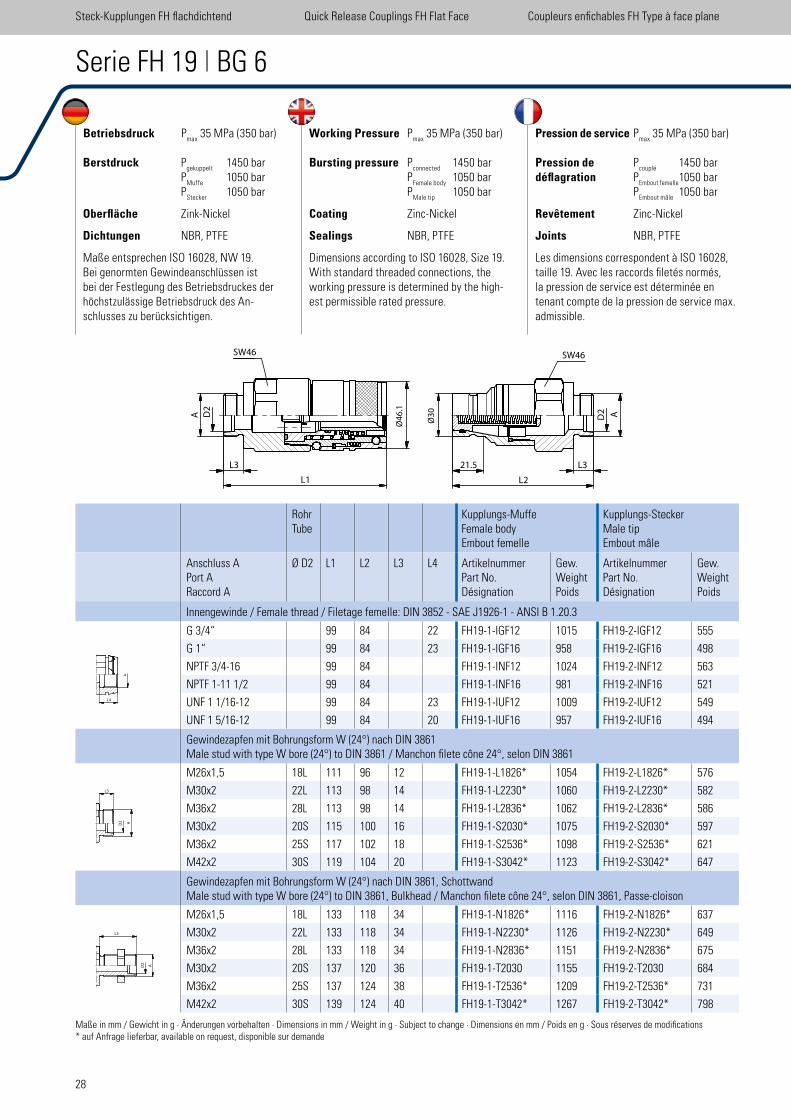
Serie FH 19 | BG 6
RohrTube
Kupplungs-MuffeFemale bodyEmbout femelle
Kupplungs-SteckerMale tipEmbout mâle
Anschluss APort ARaccord A
Ø D2 L1 L2 L3 L4 ArtikelnummerPart No.Désignation
Gew.WeightPoids
ArtikelnummerPart No.Désignation
Gew.WeightPoids
Innengewinde / Female thread / Filetage femelle: DIN 3852 - SAE J1926-1 - ANSI B 1.20.3
G 3/4“ 99 84 22 FH19-1-IGF12 1015 FH19-2-IGF12 555
G 1“ 99 84 23 FH19-1-IGF16 958 FH19-2-IGF16 498
NPTF 3/4-16 99 84 FH19-1-INF12 1024 FH19-2-INF12 563
NPTF 1-11 1/2 99 84 FH19-1-INF16 981 FH19-2-INF16 521
UNF 1 1/16-12 99 84 23 FH19-1-IUF12 1009 FH19-2-IUF12 549
UNF 1 5/16-12 99 84 20 FH19-1-IUF16 957 FH19-2-IUF16 494
Gewindezapfen mit Bohrungsform W (24°) nach DIN 3861Male stud with type W bore (24°) to DIN 3861 / Manchon ilete cône 24°, selon DIN 3861
M26x1,5 18L 111 96 12 FH19-1-L1826* 1054 FH19-2-L1826* 576
M30x2 22L 113 98 14 FH19-1-L2230* 1060 FH19-2-L2230* 582
M36x2 28L 113 98 14 FH19-1-L2836* 1062 FH19-2-L2836* 586
M30x2 20S 115 100 16 FH19-1-S2030* 1075 FH19-2-S2030* 597
M36x2 25S 117 102 18 FH19-1-S2536* 1098 FH19-2-S2536* 621
M42x2 30S 119 104 20 FH19-1-S3042* 1123 FH19-2-S3042* 647
Gewindezapfen mit Bohrungsform W (24°) nach DIN 3861, SchottwandMale stud with type W bore (24°) to DIN 3861, Bulkhead / Manchon ilete cône 24°, selon DIN 3861, Passe-cloison
M26x1,5 18L 133 118 34 FH19-1-N1826* 1116 FH19-2-N1826* 637
M30x2 22L 133 118 34 FH19-1-N2230* 1126 FH19-2-N2230* 649
M36x2 28L 133 118 34 FH19-1-N2836* 1151 FH19-2-N2836* 675
M30x2 20S 137 120 36 FH19-1-T2030 1155 FH19-2-T2030 684
M36x2 25S 137 124 38 FH19-1-T2536* 1209 FH19-2-T2536* 731
M42x2 30S 139 124 40 FH19-1-T3042* 1267 FH19-2-T3042* 798
Betriebsdruck Pmax
35 MPa (350 bar)
Berstdruck Pgekuppelt
1450 bar P
Muffe 1050 bar
PStecker
1050 bar
Oberfläche Zink-Nickel
Dichtungen NBR, PTFE
Maße entsprechen ISO 16028, NW 19.Bei genormten Gewindeanschlüssen ist bei der Festlegung des Betriebsdruckes der höchstzulässige Betriebsdruck des An-schlusses zu berücksichtigen.
Working Pressure Pmax
35 MPa (350 bar)
Bursting pressure Pconnected
1450 bar P
Female body 1050 bar
PMale tip
1050 bar
Coating Zinc-Nickel
Sealings NBR, PTFE
Dimensions according to ISO 16028, Size 19.With standard threaded connections, the working pressure is determined by the high-est permissible rated pressure.
Pression de service Pmax
35 MPa (350 bar)
Pression de Pcouplé
1450 bardéflagration P
Embout femelle 1050 bar
PEmbout mâle
1050 bar
Revêtement Zinc-Nickel
Joints NBR, PTFE
Les dimensions correspondent à ISO 16028, taille 19. Avec les raccords iletés normés, la pression de service est déterminée en tenant compte de la pression de service max. admissible.
Steck-Kupplungen FH lachdichtend Quick Release Couplings FH Flat Face Coupleurs enichables FH Type à face plane
Maße in mm / Gewicht in g · Änderungen vorbehalten · Dimensions in mm / Weight in g · Subject to change · Dimensions en mm / Poids en g · Sous réserves de modiications* auf Anfrage lieferbar, available on request, disponible sur demande
D2
A
L3
L1
SW46
Ø4
6.1
Ø3
0
21.5
L2
SW46
L3
D2 A
A
L3
L4
29
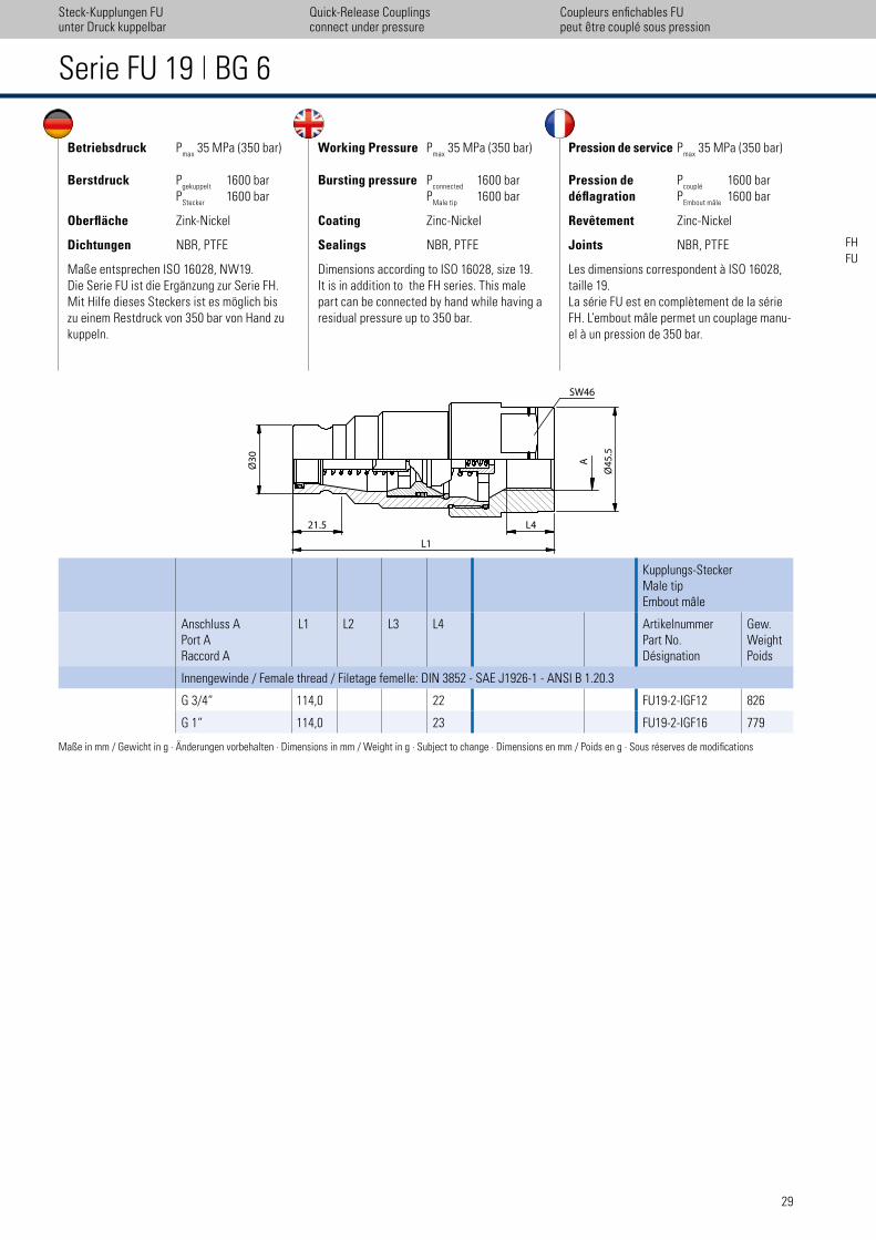
Betriebsdruck Pmax
35 MPa (350 bar)
Berstdruck Pgekuppelt
1600 bar P
Stecker 1600 bar
Oberfläche Zink-Nickel
Dichtungen NBR, PTFE
Maße entsprechen ISO 16028, NW19. Die Serie FU ist die Ergänzung zur Serie FH. Mit Hilfe dieses Steckers ist es möglich bis zu einem Restdruck von 350 bar von Hand zu kuppeln.
Working Pressure Pmax
35 MPa (350 bar)
Bursting pressure Pconnected
1600 bar P
Male tip 1600 bar
Coating Zinc-Nickel
Sealings NBR, PTFE
Dimensions according to ISO 16028, size 19. It is in addition to the FH series. This male part can be connected by hand while having a residual pressure up to 350 bar.
Pression de service Pmax
35 MPa (350 bar)
Pression de Pcouplé
1600 bardéflagration P
Embout mâle 1600 bar
Revêtement Zinc-Nickel
Joints NBR, PTFE
Les dimensions correspondent à ISO 16028, taille 19.La série FU est en complètement de la série FH. L’embout mâle permet un couplage manu-el à un pression de 350 bar.
Serie FU 19 | BG 6
Kupplungs-SteckerMale tipEmbout mâle
Anschluss APort ARaccord A
L1 L2 L3 L4 ArtikelnummerPart No.Désignation
Gew.WeightPoids
Innengewinde / Female thread / Filetage femelle: DIN 3852 - SAE J1926-1 - ANSI B 1.20.3
G 3/4“ 114,0 22 FU19-2-IGF12 826
G 1“ 114,0 23 FU19-2-IGF16 779
Maße in mm / Gewicht in g · Änderungen vorbehalten · Dimensions in mm / Weight in g · Subject to change · Dimensions en mm / Poids en g · Sous réserves de modiications
Steck-Kupplungen FUunter Druck kuppelbar
Coupleurs enichables FUpeut ´̀etre couplé sous pression
Quick-Release Couplingsconnect under pressure
SW46���
�L1�
21.5 L4
�Ø
45
.5���
A��
Ø3
0�
�FHFU
UDK-Connect
under
Pressure
30
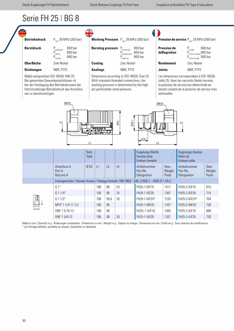
Betriebsdruck Pmax
26 MPa (260 bar)
Berstdruck Pgekuppelt
800 bar P
Muffe 800 bar
PStecker
800 bar
Oberfläche Zink-Nickel
Dichtungen NBR, PTFE
Maße entsprechen ISO 16028, NW 25.Bei genormten Gewindeanschlüssen ist bei der Festlegung des Betriebsdruckes der höchstzulässige Betriebsdruck des Anschlus-ses zu berücksichtigen.
Working Pressure Pmax
26 MPa (260 bar)
Bursting pressure Pconnected
800 bar P
Female body 800 bar
PMale tip
800 bar
Coating Zinc-Nickel
Sealings NBR, PTFE
Dimensions according to ISO 16028, Size 25.With standard threaded connections, the working pressure is determined by the high-est permissible rated pressure.
Pression de service Pmax
26 MPa (260 bar)
Pression de Pcouplé
800 bardéflagration P
Embout femelle 800 bar
PEmbout mâle
800 bar
Revêtement Zinc-Nickel
Joints NBR, PTFE
Les dimensions correspondent à ISO 16028, taille 25. Avec les raccords iletés normés, la pression de service est déterminée en tenant compte de la pression de service max. admissible.
Serie FH 25 | BG 8
RohrTube
Kupplungs-MuffeFemale bodyEmbout femelle
Kupplungs-SteckerMale tipEmbout mâle
Anschluss APort ARaccord A
Ø D2 L1 L2 L4 ArtikelnummerPart No.Désignation
Gew.WeightPoids
ArtikelnummerPart No.Désignation
Gew.WeightPoids
Innengewinde / Female thread / Filetage femelle: DIN 3852 - SAE J1926-1 - ANSI B 1.20.3
G 1“ 106 90 23 FH25-1-IGF16 1417 FH25-2-IGF16 815
G 1 1/4“ 106 90 25 FH25-1-IGF20 1301 FH25-2-IGF20 714
G 1 1/2“ 106 95,6 25 FH25-1-IGF24* 1233 FH25-2-IGF24* 704
NPTF 1 1/4-11 1/2 106 90 FH25-1-INF20 1337 FH25-2-INF20 736
UNF 1 5/16-12 106 90 FH25--1-IUF16 1405 FH25-2-IUF16 808
UNF 1 5/8-12 106 90 20 FH25-1-IUF20 1321 FH25-2-IUF20 720
Steck-Kupplungen FH lachdichtend Quick Release Couplings FH Flat Face Coupleurs enichables FH Type à face plane
Maße in mm / Gewicht in g · Änderungen vorbehalten · Dimensions in mm / Weight in g · Subject to change · Dimensions en mm / Poids en g · Sous réserves de modiications* auf Anfrage lieferbar, available on request, disponible sur demande
SW55
A
L1
Ø5
5�
Ø3
6.1
22.6
L2
A
SW55
L4
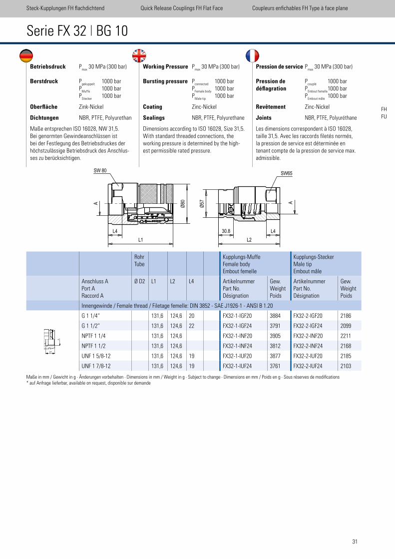
31
Steck-Kupplungen FH lachdichtend Quick Release Couplings FH Flat Face Coupleurs enichables FH Type à face plane
Serie FX 32 | BG 10
Betriebsdruck Pmax
30 MPa (300 bar)
Berstdruck Pgekuppelt
1000 bar P
Muffe 1000 bar
PStecker
1000 bar
Oberfläche Zink-Nickel
Dichtungen NBR, PTFE, Polyurethan
Maße entsprechen ISO 16028, NW 31,5.Bei genormten Gewindeanschlüssen ist bei der Festlegung des Betriebsdruckes der höchstzulässige Betriebsdruck des Anschlus-ses zu berücksichtigen.
Working Pressure Pmax
30 MPa (300 bar)
Bursting pressure Pconnected
1000 bar P
Female body 1000 bar
PMale tip
1000 bar
Coating Zinc-Nickel
Sealings NBR, PTFE, Polyurethane
Dimensions according to ISO 16028, Size 31,5.With standard threaded connections, the working pressure is determined by the high-est permissible rated pressure.
Pression de service Pmax
30 MPa (300 bar)
Pression de Pcouplé
1000 bardéflagration P
Embout femelle 1000 bar
PEmbout mâle
1000 bar
Revêtement Zinc-Nickel
Joints NBR, PTFE, Polyuréthane
Les dimensions correspondent à ISO 16028, taille 31,5. Avec les raccords iletés normés, la pression de service est déterminée en tenant compte de la pression de service max. admissible.
RohrTube
Kupplungs-MuffeFemale bodyEmbout femelle
Kupplungs-SteckerMale tipEmbout mâle
Anschluss APort ARaccord A
Ø D2 L1 L2 L4 ArtikelnummerPart No.Désignation
Gew.WeightPoids
ArtikelnummerPart No.Désignation
Gew.WeightPoids
Innengewinde / Female thread / Filetage femelle: DIN 3852 - SAE J1926-1 - ANSI B 1.20
G 1 1/4“ 131,6 124,6 20 FX32-1-IGF20 3884 FX32-2-IGF20 2186
G 1 1/2“ 131,6 124,6 22 FX32-1-IGF24 3791 FX32-2-IGF24 2099
NPTF 1 1/4 131,6 124,6 FX32-1-INF20 3905 FX32-2-INF20 2211
NPTF 1 1/2 131,6 124,6 FX32-1-INF24 3812 FX32-2-INF24 2168
UNF 1 5/8-12 131,6 124,6 19 FX32-1-IUF20 3877 FX32-2-IUF20 2185
UNF 1 7/8-12 131,6 124,6 19 FX32-1-IUF24 3761 FX32-2-IUF24 2103
Maße in mm / Gewicht in g · Änderungen vorbehalten · Dimensions in mm / Weight in g · Subject to change · Dimensions en mm / Poids en g · Sous réserves de modiications* auf Anfrage lieferbar, available on request, disponible sur demande
L4FX 32
scale 0.3
A
L4
80
Ø
L1
SW 80SW65
A
L2
L430.8
57
Ø
FHFU
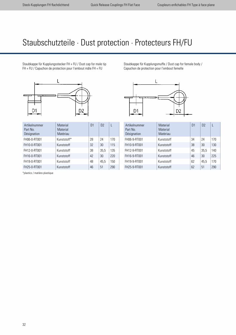
32
Staubkappe für Kupplungsstecker FH + FU / Dust cap for male tip FH + FU / Capuchon de protection pour l‘embout mâle FH + FU
ArtikelnummerPart No.Désignation
MaterialMaterialMatériau
D1 D2 L
FH06-0-RT001 Kunststoff* 28 24 170
FH10-0-RT001 Kunststoff 32 30 115
FH12-0-RT001 Kunststoff 38 35,5 135
FH16-0-RT001 Kunststoff 42 30 220
FH19-0-RT001 Kunststoff 48 45,5 150
FH25-0-RT001 Kunststoff 46 51 290
Staubkappe für Kupplungsmuffe / Dust cap for female body / Capuchon de protection pour l‘embout femelle
ArtikelnummerPart No.Désignation
MaterialMaterialMatériau
D1 D2 L
FH06-9-RT001 Kunststoff 34 24 170
FH10-9-RT001 Kunststoff 38 30 130
FH12-9-RT001 Kunststoff 45 35,5 140
FH16-9-RT001 Kunststoff 46 30 225
FH19-9-RT001 Kunststoff 62 45,5 170
FH25-9-RT001 Kunststoff 62 51 290
*plastics / matière plastique
Staubschutzteile · Dust protection · Protecteurs FH/FU
Steck-Kupplungen FH lachdichtend Quick Release Couplings FH Flat Face Coupleurs enichables FH Type à face plane
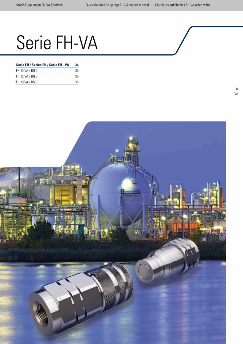
33
Serie FH / Series FH / Série FH - VA 34
FH 10 VA / BG 2 35
FH 12 VA / BG 3 35
FH 19 VA / BG 6 35
Steck-Kupplungen FH-VA Edelstahl Quick-Release Couplings FH-VA stainless steel Coupleurs enichables FH-VA acier afiné
FHVA
Serie FH-VA
Steck-Kupplungen FH-VA Edelstahl Quick-Release Couplings FH-VA stainless steel Coupleurs enichables FH-VA acier afiné
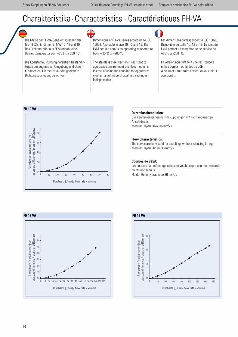
34
Durchsatz [l/min] / low rate / volume
0 20 40 60 80 100 120 140 1600,0
1,0
2,0
3,0
Bere
chne
te D
ruck
diff
eren
z [b
ar]
pres
sure
diff
eren
ce /
pre
ssio
n di
ffér
ence
Durchsatz [l/min] / low rate / volume
0 100,0
2,5
5,0
7,5
10,0
12,5
15,0
20 30 40 50 60 70 80 90 100 110 120 130 140 150 160
Bere
chne
te D
ruck
diff
eren
z [b
ar]
pres
sure
diff
eren
ce /
pre
ssio
n di
ffér
ence
FH 12 VA FH 19 VA
Durchsatz [l/min] / low rate / volume
0 100,0
2,0
4,0
6,0
8,0
20 30 40 50 60 70 80
Bere
chne
te D
ruck
diff
eren
z [b
ar]
pres
sure
diff
eren
ce /
pre
ssio
n di
ffér
ence
Die Maße der FH-VA Serie entsprechen der ISO 16028. Erhältlich in NW 10, 12 und 19. Das Dichtmaterial aus FKM erlaubt eine Betriebstemperatur von –25 bis + 200 ° C.
Die Edelstahlausführung garantiert Beständig- keiten bei aggressiver Umgebung und Durch-lussmedien. Hierbei ist auf die geeignete Dichtungsauslegung zu achten.
Dimensions of FH-VA series according to ISO 16028. Available in size 10, 12 and 19. The FKM sealing admits an operating temperature from – 25°C to +200 °C. The stainless steel version is resistant to aggressive environment and low mediums. In case of using the coupling for aggressive medium a deinition of qualiied sealing is indispensable.
Les dimensions correspondent à ISO 16028. Disponible en taille 10, 12 et 19. Le joint de FKM permet un température de service de –25°C à +200 °C.
La version acier afiné a une résistance à milieu agressif et luides de débit.A ce sujet il faut faire l’attention aux joints appropriés.
Charakteristika · Characteristics · Caractéristiques FH-VA
Durchflusskennlinien: Die Kennlinien gelten nur für Kupplungen mit nicht reduzierten Anschlüssen. Medium: Hydrauliköl 36 mm2/s
Flow characteristics: The curves are only valid for couplings without reducing itting. Medium: Hydraulic Oil 36 mm2/s
Courbes de débit: Les courbes caractéristiques ne sont valables que pour des raccorde-ments non réduits. Fluide: Huile hydraulique 36 mm2/s
FH 10 VA
Steck-Kupplungen FH-VA Edelstahl Quick-Release Couplings FH-VA stainless steel Coupleurs enichables FH-VA acier afiné
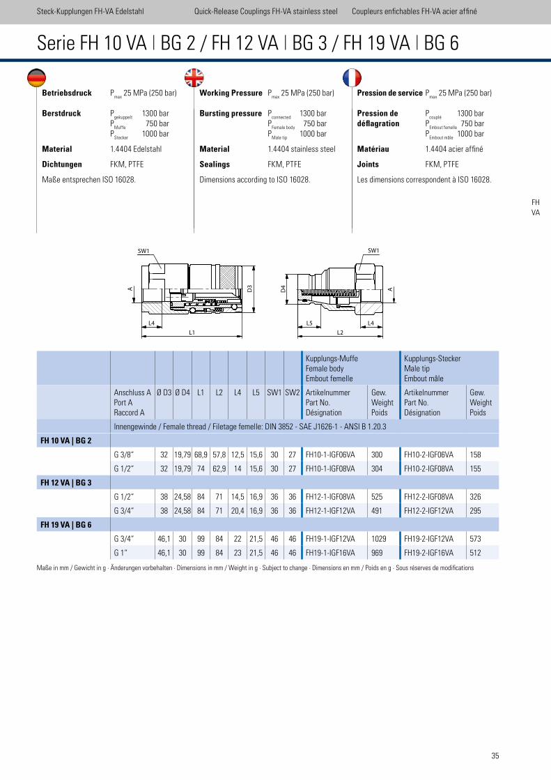
35
Steck-Kupplungen FH-VA Edelstahl Quick-Release Couplings FH-VA stainless steel Coupleurs enichables FH-VA acier afiné
FHVA
Betriebsdruck Pmax
25 MPa (250 bar)
Berstdruck Pgekuppelt
1300 bar P
Muffe 750 bar
PStecker
1000 bar
Material 1.4404 Edelstahl
Dichtungen FKM, PTFE
Maße entsprechen ISO 16028.
Working Pressure Pmax
25 MPa (250 bar)
Bursting pressure Pconnected
1300 bar P
Female body 750 bar
PMale tip
1000 bar
Material 1.4404 stainless steel
Sealings FKM, PTFE
Dimensions according to ISO 16028.
Pression de service Pmax
25 MPa (250 bar)
Pression de Pcouplé
1300 bardéflagration P
Embout femelle 750 bar
PEmbout mâle
1000 bar
Matériau 1.4404 acier afiné
Joints FKM, PTFE
Les dimensions correspondent à ISO 16028.
Serie FH 10 VA | BG 2 / FH 12 VA | BG 3 / FH 19 VA | BG 6
Kupplungs-MuffeFemale bodyEmbout femelle
Kupplungs-SteckerMale tipEmbout mâle
Anschluss APort ARaccord A
Ø D3 Ø D4 L1 L2 L4 L5 SW1 SW2 ArtikelnummerPart No.Désignation
Gew.WeightPoids
ArtikelnummerPart No.Désignation
Gew.WeightPoids
Innengewinde / Female thread / Filetage femelle: DIN 3852 - SAE J1626-1 - ANSI B 1.20.3
FH 10 VA | BG 2
G 3/8“ 32 19,79 68,9 57,8 12,5 15,6 30 27 FH10-1-IGF06VA 300 FH10-2-IGF06VA 158
G 1/2“ 32 19,79 74 62,9 14 15,6 30 27 FH10-1-IGF08VA 304 FH10-2-IGF08VA 155
FH 12 VA | BG 3
G 1/2“ 38 24,58 84 71 14,5 16,9 36 36 FH12-1-IGF08VA 525 FH12-2-IGF08VA 326
G 3/4“ 38 24,58 84 71 20,4 16,9 36 36 FH12-1-IGF12VA 491 FH12-2-IGF12VA 295
FH 19 VA | BG 6
G 3/4“ 46,1 30 99 84 22 21,5 46 46 FH19-1-IGF12VA 1029 FH19-2-IGF12VA 573
G 1“ 46,1 30 99 84 23 21,5 46 46 FH19-1-IGF16VA 969 FH19-2-IGF16VA 512
Maße in mm / Gewicht in g · Änderungen vorbehalten · Dimensions in mm / Weight in g · Subject to change · Dimensions en mm / Poids en g · Sous réserves de modiications
SW1
A
L1
D3�
SW1
D4�
L5 L4L4
L2
A

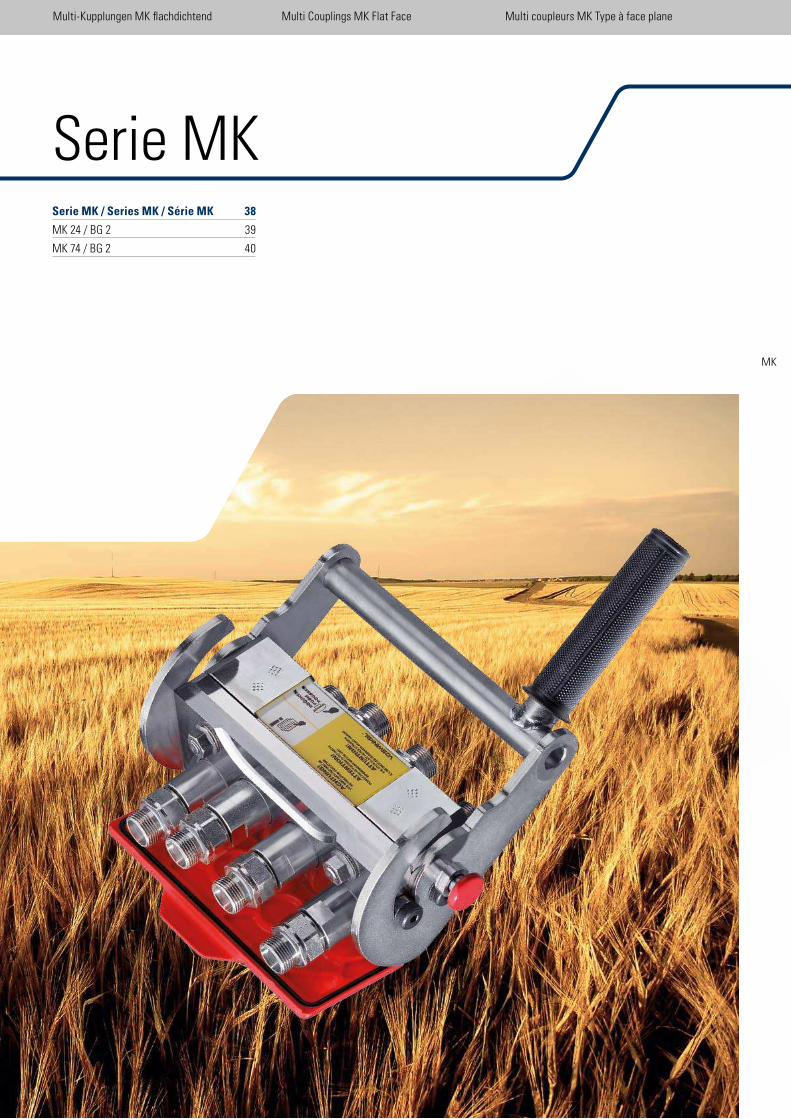
37
Serie MK / Series MK / Série MK 38
MK 24 / BG 2 39
MK 74 / BG 2 40
Multi-Kupplungen MK lachdichtend Multi Couplings MK Flat Face Multi coupleurs MK Type à face plane
Serie MK
MK
Multi-Kupplungen MK lachdichtend Multi Couplings MK Flat Face Multi coupleurs MK Type à face plane
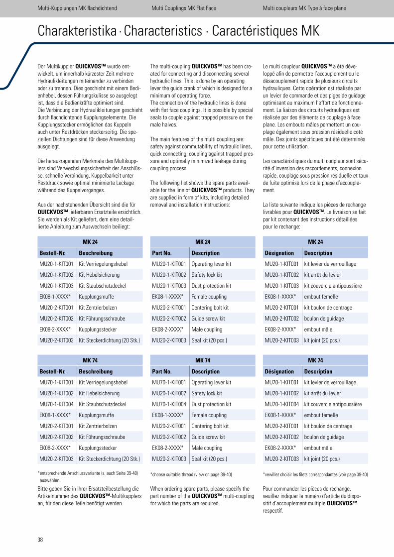
38
Le multi coupleur QUICKVOSTM a été déve-loppé ain de permettre l’accouplement ou le désacouplement rapide de plusieurs circuits hydrauliques. Cette opération est réalisée par un levier de commande et des piges de guidage optimisant au maximum l’effort de fonctionne-ment. La liaison des circuits hydrauliques est réalisée par des éléments de couplage à face plane. Les embouts mâles permettent un cou-plage également sous pression résiduelle coté mâle. Des joints spéciiques ont été déterminés pour cette utilisation.
Les caractéristiques du multi coupleur sont sécu-rité d’inversion des raccordements, connexion rapide, couplage sous pression résiduelle et taux de fuite optimisé lors de la phase d’accouple-ment.
La liste suivante indique les pièces de rechange livrables pour QUICKVOSTM. La livraison se fait par kit contenant des instructions détaillées pour le rechange:
*vewillez choisir les ilets correspondantes (voir page 39-40)
Pour commander les pièces de rechange, veuillez indiquer le numéro d’article du dispo-sitif d’accouplement multiple QUICKVOSTM respectif.
The multi-coupling QUICKVOSTM has been cre-ated for connecting and disconnecting several hydraulic lines. This is done by an operating lever the guide crank of which is designed for a minimum of operating force.The connection of the hydraulic lines is done with lat face couplings. It is possible by special seals to couple against trapped pressure on the male halves.
The main features of the multi coupling are: safety against commutability of hydraulic lines, quick connecting, coupling against trapped pres-sure and optimally minimized leakage during coupling process.
The following list shows the spare parts avail-able for the line of QUICKVOSTM products. They are supplied in form of kits, including detailed removal and installation instructions:
*choose suitable thread (view on page 39-40)
When ordering spare parts, please specify the part number of the QUICKVOSTM multi-coupling for which the parts are required.
Der Multikuppler QUICKVOSTM wurde ent-wickelt, um innerhalb kürzester Zeit mehrere Hydraulikleitungen miteinander zu verbinden oder zu trennen. Dies geschieht mit einem Bedi-enhebel, dessen Führungskulisse so ausgelegt ist, dass die Bedienkräfte optimiert sind.Die Verbindung der Hydraulikleitungen geschieht durch lachdichtende Kupplungselemente. Die Kupplungsstecker ermöglichen das Kuppeln auch unter Restdrücken steckerseitig. Die spe-ziellen Dichtungen sind für diese Anwendung ausgelegt.
Die herausragenden Merkmale des Multikupp-lers sind Verwechslungssicherheit der Anschlüs-se, schnelle Verbindung, Kuppelbarkeit unter Restdruck sowie optimal minimierte Leckage während des Kuppelvorganges.
Aus der nachstehenden Übersicht sind die für QUICKVOSTM lieferbaren Ersatzteile ersichtlich. Sie werden als Kit geliefert, dem eine detail-lierte Anleitung zum Auswechseln beiliegt:
*entsprechende Anschlussvariante (s. auch Seite 39-40)
auswählen.
Bitte geben Sie in Ihrer Ersatzteilbestellung die Artikelnummer des QUICKVOSTM-Multikupplers an, für den diese Teile benötigt werden.
MK 74
Bestell-Nr. Beschreibung
MU70-1-KIT001 Kit Verriegelungshebel
MU20-1-KIT002 Kit Hebelsicherung
MU70-1-KIT004 Kit Staubschutzdeckel
EK08-1-XXXX* Kupplungsmuffe
MU20-2-KIT001 Kit Zentrierbolzen
MU20-2-KIT002 Kit Führungsschraube
EK08-2-XXXX* Kupplungsstecker
MU20-2-KIT003 Kit Steckerdichtung (20 Stk.)
MK 74
Part No. Description
MU70-1-KIT001 Operating lever kit
MU20-1-KIT002 Safety lock kit
MU70-1-KIT004 Dust protection kit
EK08-1-XXXX* Female coupling
MU20-2-KIT001 Centering bolt kit
MU20-2-KIT002 Guide screw kit
EK08-2-XXXX* Male coupling
MU20-2-KIT003 Seal kit (20 pcs.)
MK 74
Désignation Description
MU70-1-KIT001 kit levier de verrouillage
MU20-1-KIT002 kit arrêt du levier
MU70-1-KIT004 kit couvercle antipoussière
EK08-1-XXXX* embout femelle
MU20-2-KIT001 kit boulon de centrage
MU20-2-KIT002 boulon de guidage
EK08-2-XXXX* embout mâle
MU20-2-KIT003 kit joint (20 pcs.)
Charakteristika · Characteristics · Caractéristiques MK
Multi-Kupplungen MK lachdichtend Multi Couplings MK Flat Face Multi coupleurs MK Type à face plane
MK 24
Bestell-Nr. Beschreibung
MU20-1-KIT001 Kit Verriegelungshebel
MU20-1-KIT002 Kit Hebelsicherung
MU20-1-KIT003 Kit Staubschutzdeckel
EK08-1-XXXX* Kupplungsmuffe
MU20-2-KIT001 Kit Zentrierbolzen
MU20-2-KIT002 Kit Führungsschraube
EK08-2-XXXX* Kupplungsstecker
MU20-2-KIT003 Kit Steckerdichtung (20 Stk.)
MK 24
Part No. Description
MU20-1-KIT001 Operating lever kit
MU20-1-KIT002 Safety lock kit
MU20-1-KIT003 Dust protection kit
EK08-1-XXXX* Female coupling
MU20-2-KIT001 Centering bolt kit
MU20-2-KIT002 Guide screw kit
EK08-2-XXXX* Male coupling
MU20-2-KIT003 Seal kit (20 pcs.)
MK 24
Désignation Description
MU20-1-KIT001 kit levier de verrouillage
MU20-1-KIT002 kit arrêt du levier
MU20-1-KIT003 kit couvercle antipoussière
EK08-1-XXXX* embout femelle
MU20-2-KIT001 kit boulon de centrage
MU20-2-KIT002 boulon de guidage
EK08-2-XXXX* embout mâle
MU20-2-KIT003 kit joint (20 pcs.)
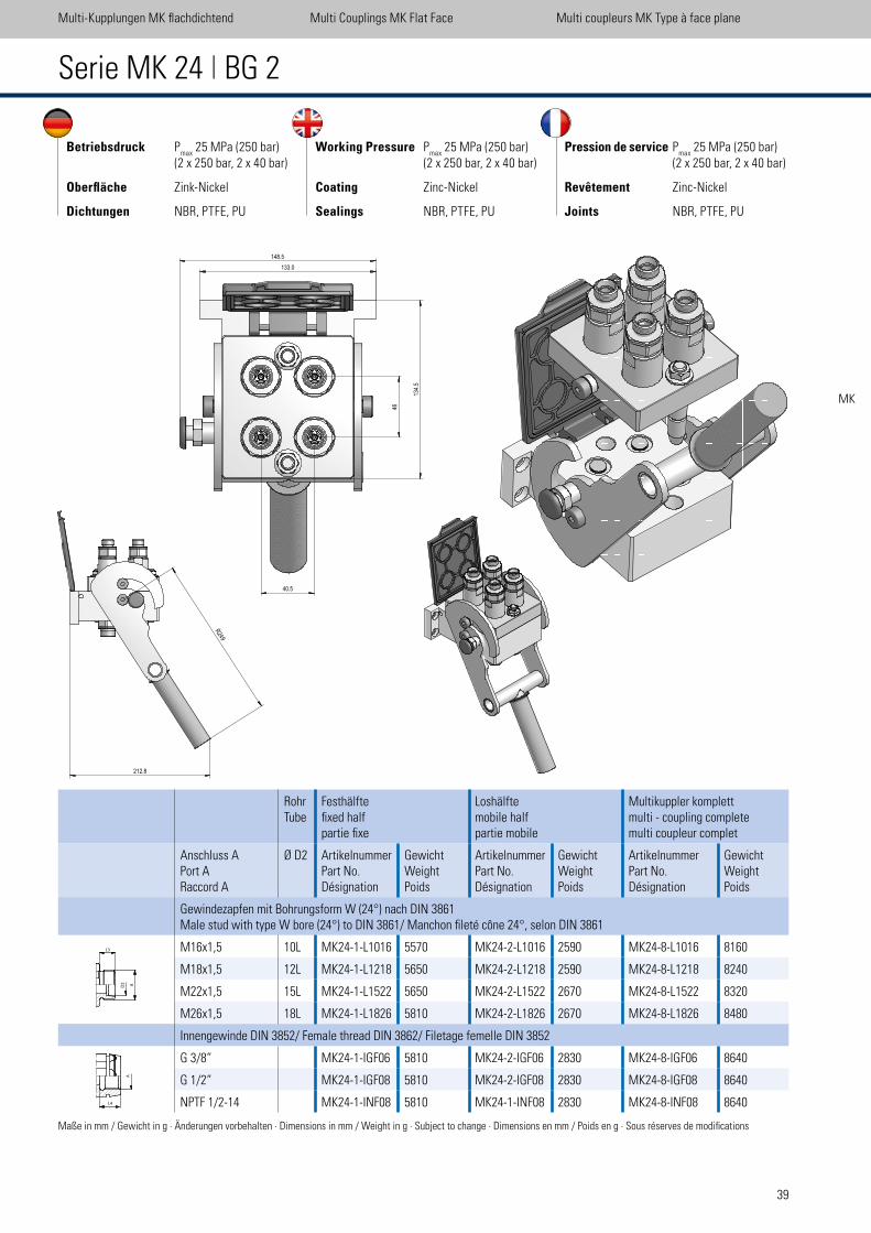
39
RohrTube
Festhälfteixed halfpartie ixe
Loshälftemobile half partie mobile
Multikuppler komplettmulti - coupling completemulti coupleur complet
Anschluss APort ARaccord A
Ø D2 ArtikelnummerPart No.Désignation
GewichtWeightPoids
ArtikelnummerPart No.Désignation
GewichtWeightPoids
ArtikelnummerPart No.Désignation
GewichtWeightPoids
Gewindezapfen mit Bohrungsform W (24°) nach DIN 3861 Male stud with type W bore (24°) to DIN 3861/ Manchon ileté cône 24°, selon DIN 3861
M16x1,5 10L MK24-1-L1016 5570 MK24-2-L1016 2590 MK24-8-L1016 8160
M18x1,5 12L MK24-1-L1218 5650 MK24-2-L1218 2590 MK24-8-L1218 8240
M22x1,5 15L MK24-1-L1522 5650 MK24-2-L1522 2670 MK24-8-L1522 8320
M26x1,5 18L MK24-1-L1826 5810 MK24-2-L1826 2670 MK24-8-L1826 8480
Innengewinde DIN 3852/ Female thread DIN 3862/ Filetage femelle DIN 3852
G 3/8“ MK24-1-IGF06 5810 MK24-2-IGF06 2830 MK24-8-IGF06 8640
G 1/2“ MK24-1-IGF08 5810 MK24-2-IGF08 2830 MK24-8-IGF08 8640
NPTF 1/2-14 MK24-1-INF08 5810 MK24-1-INF08 2830 MK24-8-INF08 8640
Serie MK 24 | BG 2
Multi-Kupplungen MK lachdichtend Multi Couplings MK Flat Face Multi coupleurs MK Type à face plane
MK
Betriebsdruck Pmax
25 MPa (250 bar) (2 x 250 bar, 2 x 40 bar)
Oberfläche Zink-Nickel
Dichtungen NBR, PTFE, PU
Working Pressure Pmax
25 MPa (250 bar) (2 x 250 bar, 2 x 40 bar)
Coating Zinc-Nickel
Sealings NBR, PTFE, PU
Pression de service Pmax
25 MPa (250 bar) (2 x 250 bar, 2 x 40 bar)
Revêtement Zinc-Nickel
Joints NBR, PTFE, PU
Maße in mm / Gewicht in g · Änderungen vorbehalten · Dimensions in mm / Weight in g · Subject to change · Dimensions en mm / Poids en g · Sous réserves de modiications
L4
A
L3
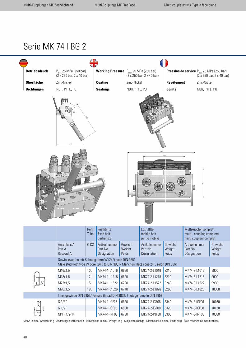
40
RohrTube
Festhälfteixed halfpartie ixe
Loshälftemobile half partie mobile
Multikuppler komplettmulti - coupling completemulti coupleur complet
Anschluss APort ARaccord A
Ø D2 ArtikelnummerPart No.Désignation
GewichtWeightPoids
ArtikelnummerPart No.Désignation
GewichtWeightPoids
ArtikelnummerPart No.Désignation
GewichtWeightPoids
Gewindezapfen mit Bohrungsform W (24°) nach DIN 3861Male stud with type W bore (24°) to DIN 3861/ Manchon ileté cône 24°, selon DIN 3861
M16x1,5 10L MK74-1-L1016 6690 MK74-2-L1016 3210 MK74-8-L1016 9900
M18x1,5 12L MK74-1-L1218 6690 MK74-2-L1218 3210 MK74-8-L1218 9900
M22x1,5 15L MK74-1-L1522 6720 MK74-2-L1522 3240 MK74-8-L1522 9960
M26x1,5 18L MK74-1-L1826 6740 MK74-2-L1826 3260 MK74-8-L1826 10000
Innengewinde DIN 3852/ Female thread DIN 3862/ Filetage femelle DIN 3852
G 3/8“ MK74-1-IGF06 6820 MK74-2-IGF06 3340 MK74-8-IGF06 10160
G 1/2“ MK74-1-IGF08 6800 MK74-2-IGF08 3320 MK74-8-IGF08 10120
NPTF 1/2-14 MK74-1-INF08 6780 MK74-2-INF08 3300 MK74-8-INF08 10080
Serie MK 74 | BG 2
Multi-Kupplungen MK lachdichtend Multi Couplings MK Flat Face Multi coupleurs MK Type à face plane
Betriebsdruck Pmax
25 MPa (250 bar) (2 x 250 bar, 2 x 40 bar)
Oberfläche Zink-Nickel
Dichtungen NBR, PTFE, PU
Working Pressure Pmax
25 MPa (250 bar) (2 x 250 bar, 2 x 40 bar)
Coating Zinc-Nickel
Sealings NBR, PTFE, PU
Pression de service Pmax
25 MPa (250 bar) (2 x 250 bar, 2 x 40 bar)
Revêtement Zinc-Nickel
Joints NBR, PTFE, PU
Maße in mm / Gewicht in g · Änderungen vorbehalten · Dimensions in mm / Weight in g · Subject to change · Dimensions en mm / Poids en g · Sous réserves de modiications
L4
A
L3
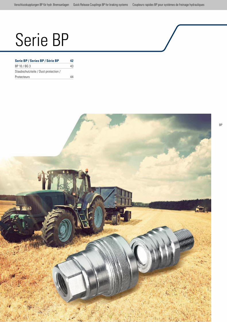
Serie BP / Series BP / Série BP 42
BP 10 / BG 3 43
Staubschutzteile / Dust protection /
Protecteurs 44
Serie BP
Verschlusskupplungen BP für hydr. Bremsanlagen Quick Release Couplings BP for braking systems Coupleurs rapides BP pour systèmes de freinage hydrauliques
BP
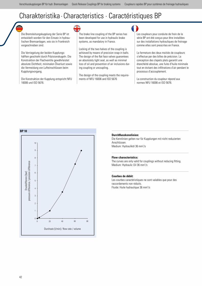
42
Die Bremsleitungskupplung der Serie BP ist entwickelt worden für den Einsatz in hydrau-lischen Bremsanlagen, wie sie in Frankreich vorgeschrieben sind.
Die Verriegelung der beiden Kupplungs-hälften geschieht durch Präzisionskugeln. Die Konstruktion der Flachventile gewährleistet absolute Dichtheit, minimalen Ölverlust sowie die Vermeidung von Lufteinschlüssen beim Kupplungsvorgang.
Die Konstruktion der Kupplung entspricht NFU 16006 und ISO 5676.
Durchflusskennlinien:Die Kennlinien gelten nur für Kupplungen mit nicht reduzierten Anschlüssen. Medium: Hydrauliköl 36 mm2/s
Flow characteristics: The curves are only valid for couplings without reducing itting. Medium: Hydraulic Oil 36 mm2/s
Courbes de débit: Les courbes caractéristiques ne sont valables que pour desraccordements non réduits. Fluide: Huile hydraulique 36 mm2/s
The brake line coupling of the BP series has been developed for use in hydraulic brake systems, as mandatory in France.
Locking of the two halves of the coupling is achieved by means of precision snap-in balls. The design of the lat face valves guarantees an absolutely tight seal, as well as minimal loss of oil and prevention of air inclusions dur-ing coupling or uncoupling.
The design of the coupling meets the require-ments of NFU 16006 and ISO 5676
Les coupleurs pour conduite de frein de la série BP ont été conçus pour être installées sur des installations hydrauliques de freinage comme elles sont prescrites en France.
La fermeture des deux moitiés de coupleurs s’effectue par des billes de précision. La conception des clapets plats garantit une étanchéité absolue, une fuite d’huile minimale tout en évitant des iniltrations d’air pendant le processus d’accouplement.
La construction du coupleur répond aux normes NFU 16006 et ISO 5676.
Charakteristika · Characteristics · Caractéristiques BP
Verschlusskupplungen BP für hydr. Bremsanlagen Quick Release Couplings BP for braking systems Coupleurs rapides BP pour systèmes de freinage hydrauliques
BP 10
Dru
ckdi
ffer
enz
[bar
]pr
essu
re d
iffer
ence
/ p
ress
ion
diff
éren
ce
Durchsatz [l/min] / low rate / volume
00
1
2
3
4
5
6
7
8
9
10
20 40 60 80
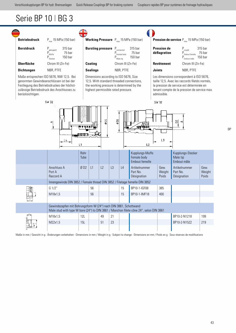
43
Betriebsdruck Pmax
15 MPa (150 bar)
Berstdruck Pgekuppelt
315 bar P
Muffe 75 bar
PStecker
150 bar
Oberfläche Chrom III (Zn-Fe)
Dichtungen NBR, PTFE
Maße entsprechen ISO 5676, NW 12,5. Bei genormten Gewindeanschlüssen ist bei der Festlegung des Betriebsdruckes der höchst-zulässige Betriebsdruck des Anschlusses zu berücksichtigen.
Working Pressure Pmax
15 MPa (150 bar)
Bursting pressure Pconnected
315 bar P
Female body 75 bar
PMale tip
150 bar
Coating Chrom III (Zn-Fe)
Sealings NBR, PTFE
Dimensions according to ISO 5676, Size 12,5. With standard threaded connections, the working pressure is determined by the highest permissible rated pressure.
Pression de service Pmax
15 MPa (150 bar)
Pression de Pcouplé
315 bardéflagration P
Embout femelle 75 bar
PEmbout mâle
150 bar
Revêtement Chrom III (Zn-Fe)
Joints NBR, PTFE
Les dimensions correspondent à ISO 5676, taille 12,5. Avec les raccords iletés normés, la pression de service est déterminée en tenant compte de la pression de service max. admissible.
Serie BP 10 | BG 3
RohrTube
Kupplungs-MuffeFemale bodyEmbout femelle
Kupplungs-SteckerMale tipEmbout mâle
Anschluss APort ARaccord A
Ø D2 L1 L2 L3 L4 ArtikelnummerPart No.Désignation
Gew.WeightPoids
ArtikelnummerPart No.Désignation
Gew.WeightPoids
Innengewinde DIN 3852 / Female thread DIN 3852 / Filetage femelle DIN 3852
G 1/2“ 56 15 BP10-1-IGF08 385
M18x1,5 56 15 BP10-1-IMF18 400
Gewindezapfen mit Bohrungsform W (24°) nach DIN 3861, SchottwandMale stud with type W bore (24°) to DIN 3861 / Manchon ilete cône 24°, selon DIN 3861
M18x1,5 12L 49 21 BP10-2-N1218 199
M22x1,5 15L 51 23 BP10-2-N1522 219
Maße in mm / Gewicht in g · Änderungen vorbehalten · Dimensions in mm / Weight in g · Subject to change · Dimensions en mm / Poids en g · Sous réserves de modiications
Verschlusskupplungen BP für hydr. Bremsanlagen Quick Release Couplings BP for braking systems Coupleurs rapides BP pour systèmes de freinage hydrauliques
BP
L4
A
L3
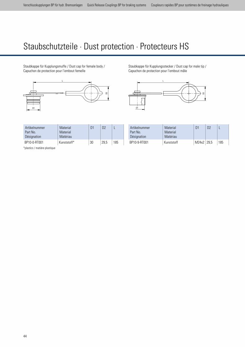
Staubkappe für Kupplungsstecker / Dust cap for male tip /Capuchon de protection pour l‘embout mâle
ArtikelnummerPart No.Désignation
MaterialMaterialMatériau
D1 D2 L
BP10-0-RT001 Kunststoff* 30 29,5 185
Staubkappe für Kupplungsmuffe / Dust cap for female body / Capuchon de protection pour l‘embout femelle
*plastics / matière plastique
ArtikelnummerPart No.Désignation
MaterialMaterialMatériau
D1 D2 L
BP10-9-RT001 Kunststoff M24x2 29,5 185
Staubschutzteile · Dust protection · Protecteurs HS
Verschlusskupplungen BP für hydr. Bremsanlagen Quick Release Couplings BP for braking systems Coupleurs rapides BP pour systèmes de freinage hydrauliques
Staubschutz BP
scale 0.77
Schraffuren bitte unter 45° oder 135° anlegen
D1D2
L
Staubschutz BP
scale 0.77
Schraffuren bitte unter 45° oder 135° anlegen
D2
L
D1
44
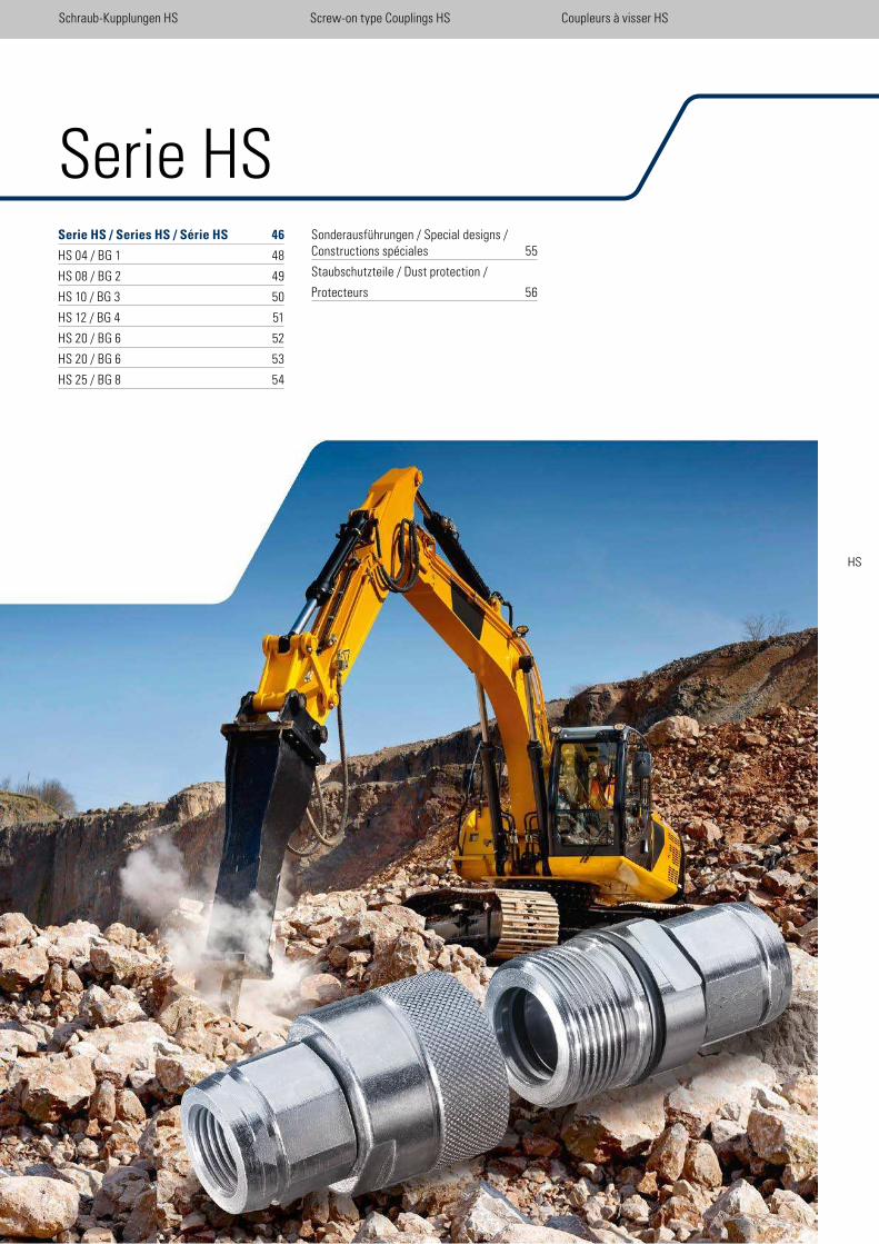
Sonderausführungen / Special designs / Constructions spéciales 55
Staubschutzteile / Dust protection /
Protecteurs 56
Serie HSSerie HS / Series HS / Série HS 46
HS 04 / BG 1 48
HS 08 / BG 2 49
HS 10 / BG 3 50
HS 12 / BG 4 51
HS 20 / BG 6 52
HS 20 / BG 6 53
HS 25 / BG 8 54
Schraub-Kupplungen HS Screw-on type Couplings HS Coupleurs à visser HS
HS
Schraub-Kupplungen HS Screw-on type Couplings HS Coupleurs à visser HS
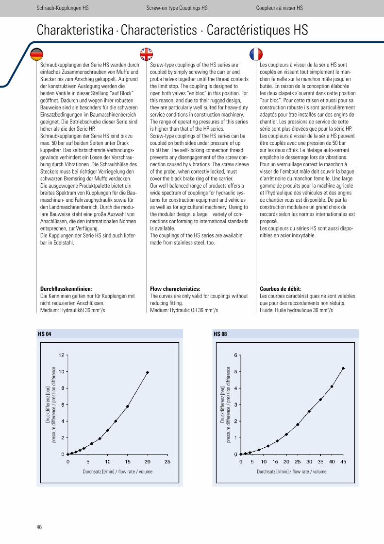
46
Schraub-Kupplungen HS Screw-on type Couplings HS Coupleurs à visser HS
Schraubkupplungen der Serie HS werden durch einfaches Zusammenschrauben von Muffe und Stecker bis zum Anschlag gekuppelt. Aufgrund der konstruktiven Auslegung werden die beiden Ventile in dieser Stellung “auf Block“ geöffnet. Dadurch und wegen ihrer robusten Bauweise sind sie besonders für die schweren Einsatzbedingungen im Baumaschinenbereich geeignet. Die Betriebsdrücke dieser Serie sind höher als die der Serie HP.Schraubkupplungen der Serie HS sind bis zu max. 50 bar auf beiden Seiten unter Druck kuppelbar. Das selbstsichernde Verbindungs-gewinde verhindert ein Lösen der Verschrau-bung durch Vibrationen. Die Schraubhülse des Steckers muss bei richtiger Verriegelung den schwarzen Bremsring der Muffe verdecken.Die ausgewogene Produktpalette bietet ein breites Spektrum von Kupplungen für die Bau-maschinen- und Fahrzeughydraulik sowie für den Landmaschinenbereich. Durch die modu-lare Bauweise steht eine große Auswahl von Anschlüssen, die den internationalen Normen entsprechen, zur Verfügung.Die Kupplungen der Serie HS sind auch liefer-bar in Edelstahl.
Screw-type couplings of the HS series are coupled by simply screwing the carrier and probe halves together until the thread contacts the limit stop. The coupling is designed to open both valves “en bloc“ in this position. For this reason, and due to their rugged design, they are particularly well suited for heavy-duty service conditions in construction machinery. The range of operating pressures of this series is higher than that of the HP series.Screw-type couplings of the HS series can be coupled on both sides under pressure of up to 50 bar. The self-locking connection thread prevents any disengagement of the screw con-nection caused by vibrations. The screw sleeve of the probe, when correctly locked, must cover the black brake ring of the carrier.Our well-balanced range of products offers a wide spectrum of couplings for hydraulic sys-tems for construction equipment and vehicles as well as for agricultural machinery. Owing to the modular design, a large variety of con-nections conforming to international standards is available.The couplings of the HS series are available made from stainless steel, too.
Les coupleurs à visser de la série HS sont couplés en vissant tout simplement le man-chon femelle sur le manchon mâle jusqu’en butée. En raison de la conception élaborée les deux clapets s’ouvrent dans cette position “sur bloc“. Pour cette raison et aussi pour sa construction robuste ils sont particulièrement adaptés pour être installés sur des engins de chantier. Les pressions de service de cette série sont plus élevées que pour la série HP.Les coupleurs à visser de la série HS peuvent être couplés avec une pression de 50 bar sur les deux côtés. Le iletage auto-serrant empêche le desserrage lors de vibrations. Pour un verrouillage correct le manchon à visser de l’embout mâle doit couvrir la bague d’arrêt noire du manchon femelle. Une large gamme de produits pour la machine agricole et l’hydraulique des véhicules et des engins de chantier vous est disponible. De par la construction modulaire un grand choix de raccords selon les normes internationales est proposé.Les coupleurs du séries HS sont aussi dispo-nibles en acier inoxydable.
Charakteristika · Characteristics · Caractéristiques HS
HS 04
Dru
ckdi
ffer
enz
[bar
]pr
essu
re d
iffer
ence
/ p
ress
ion
diff
éren
ce
Durchsatz [l/min] / low rate / volume
Durchflusskennlinien: Die Kennlinien gelten nur für Kupplungen mit nicht reduzierten Anschlüssen. Medium: Hydrauliköl 36 mm2/s
Flow characteristics: The curves are only valid for couplings without reducing itting. Medium: Hydraulic Oil 36 mm2/s
Courbes de débit: Les courbes caractéristiques ne sont valables que pour des raccordements non réduits. Fluide: Huile hydraulique 36 mm2/s
HS 08
Dru
ckdi
ffer
enz
[bar
]pr
essu
re d
iffer
ence
/ p
ress
ion
diff
éren
ce
Durchsatz [l/min] / low rate / volume
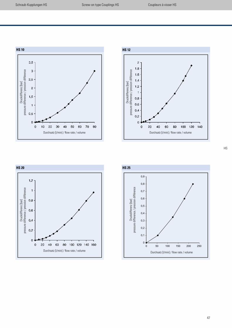
47
Schraub-Kupplungen HS Screw-on type Couplings HS Coupleurs à visser HS
HS 20
Dru
ckdi
ffer
enz
[bar
]pr
essu
re d
iffer
ence
/ p
ress
ion
diff
éren
ce
Durchsatz [l/min] / low rate / volume
HS 10
Dru
ckdi
ffer
enz
[bar
]pr
essu
re d
iffer
ence
/ p
ress
ion
diff
éren
ce
Durchsatz [l/min] / low rate / volume
HS 12
Dru
ckdi
ffer
enz
[bar
]pr
essu
re d
iffer
ence
/ p
ress
ion
diff
éren
ceDurchsatz [l/min] / low rate / volume
HS 25
Dru
ckdi
ffer
enz
[bar
]pr
essu
re d
iffer
ence
/ p
ress
ion
diff
éren
ce
Durchsatz [l/min] / low rate / volume
HS
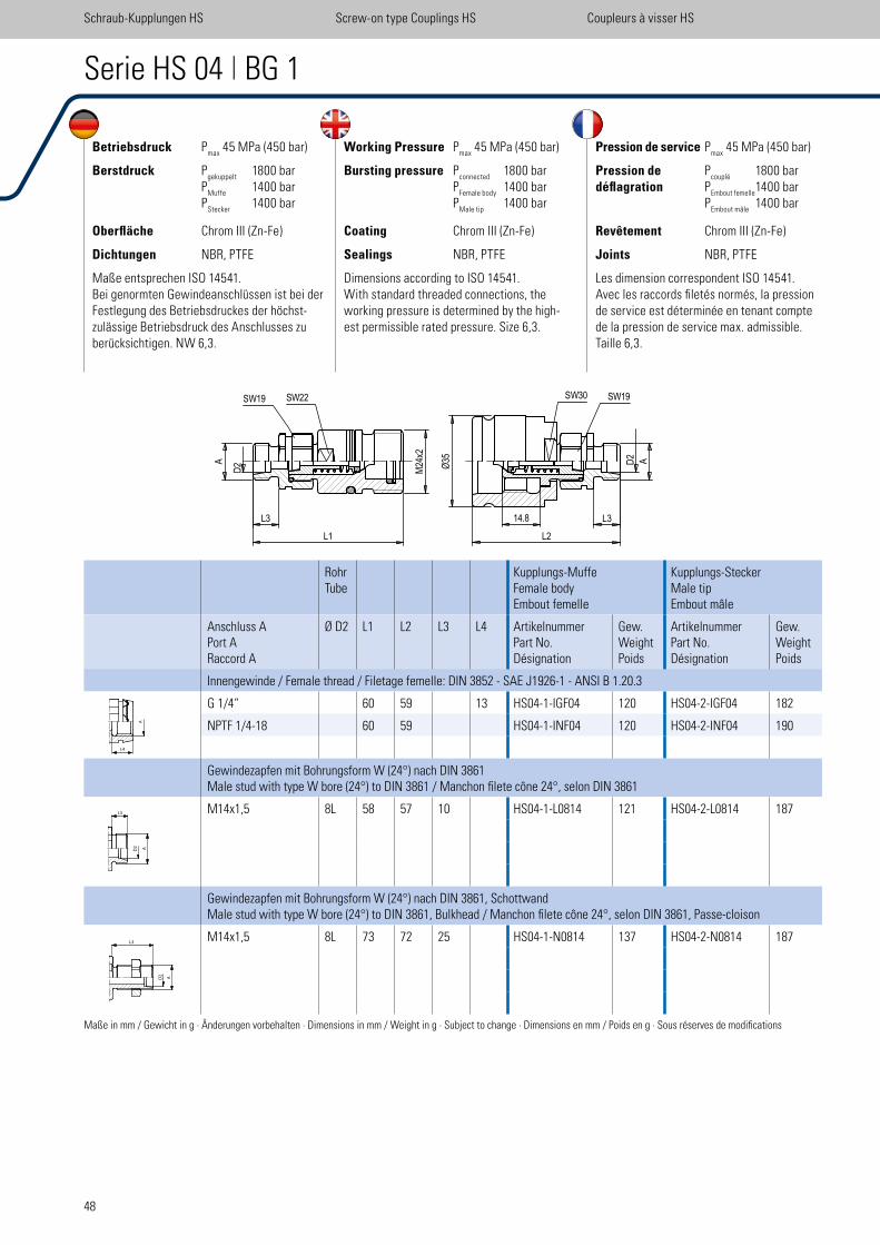
48
Betriebsdruck Pmax
45 MPa (450 bar)
Berstdruck Pgekuppelt
1800 bar P
Muffe 1400 bar
PStecker
1400 bar
Oberfläche Chrom III (Zn-Fe)
Dichtungen NBR, PTFE
Maße entsprechen ISO 14541. Bei genormten Gewindeanschlüssen ist bei der Festlegung des Betriebsdruckes der höchst-zulässige Betriebsdruck des Anschlusses zu berücksichtigen. NW 6,3.
Working Pressure Pmax
45 MPa (450 bar)
Bursting pressure Pconnected
1800 bar P
Female body 1400 bar
PMale tip
1400 bar
Coating Chrom III (Zn-Fe)
Sealings NBR, PTFE
Dimensions according to ISO 14541. With standard threaded connections, the working pressure is determined by the high-est permissible rated pressure. Size 6,3.
Pression de service Pmax
45 MPa (450 bar)
Pression de Pcouplé
1800 bar déflagration P
Embout femelle 1400 bar
PEmbout mâle
1400 bar
Revêtement Chrom III (Zn-Fe)
Joints NBR, PTFE
Les dimension correspondent ISO 14541. Avec les raccords iletés normés, la pression de service est déterminée en tenant compte de la pression de service max. admissible. Taille 6,3.
Serie HS 04 | BG 1
RohrTube
Kupplungs-MuffeFemale bodyEmbout femelle
Kupplungs-SteckerMale tipEmbout mâle
Anschluss APort ARaccord A
Ø D2 L1 L2 L3 L4 ArtikelnummerPart No.Désignation
Gew.WeightPoids
ArtikelnummerPart No.Désignation
Gew.WeightPoids
Innengewinde / Female thread / Filetage femelle: DIN 3852 - SAE J1926-1 - ANSI B 1.20.3
G 1/4“ 60 59 13 HS04-1-IGF04 120 HS04-2-IGF04 182
NPTF 1/4-18 60 59 HS04-1-INF04 120 HS04-2-INF04 190
Gewindezapfen mit Bohrungsform W (24°) nach DIN 3861Male stud with type W bore (24°) to DIN 3861 / Manchon ilete cône 24°, selon DIN 3861
M14x1,5 8L 58 57 10 HS04-1-L0814 121 HS04-2-L0814 187
Gewindezapfen mit Bohrungsform W (24°) nach DIN 3861, SchottwandMale stud with type W bore (24°) to DIN 3861, Bulkhead / Manchon ilete cône 24°, selon DIN 3861, Passe-cloison
M14x1,5 8L 73 72 25 HS04-1-N0814 137 HS04-2-N0814 187
Maße in mm / Gewicht in g · Änderungen vorbehalten · Dimensions in mm / Weight in g · Subject to change · Dimensions en mm / Poids en g · Sous réserves de modiications
Schraub-Kupplungen HS Screw-on type Couplings HS Coupleurs à visser HS
A
L3
L4
HS 04
scale 0,91
L3
L1
D2A 2
4M
x2
SW19 SW22
14.8
L2
35
Ø
L3
AD2
SW30 SW19
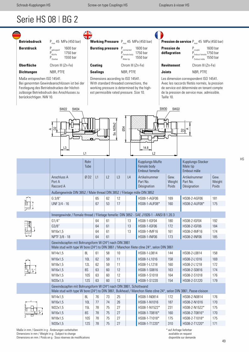
49
Betriebsdruck Pmax
45 MPa (450 bar)
Berstdruck Pgekuppelt
1600 bar P
Muffe 1750 bar
PStecker
1550 bar
Oberfläche Chrom III (Zn-Fe)
Dichtungen NBR, PTFE
Maße entsprechen ISO 14541. Bei genormten Gewindeanschlüssen ist bei der Festlegung des Betriebsdruckes der höchst-zulässige Betriebsdruck des Anschlusses zu berücksichtigen. NW 10.
Working Pressure Pmax
45 MPa (450 bar)
Bursting pressure Pconnected
1600 bar P
Female body 1750 bar
PMale tip
1550 bar
Coating Chrom III (Zn-Fe)
Sealings NBR, PTFE
Dimensions according to ISO 14541. With standard threaded connections, the working pressure is determined by the high-est permissible rated pressure. Size 10.
Pression de service Pmax
45 MPa (450 bar)
Pression de Pcouplé
1600 bar déflagration P
Embout femelle 1750 bar
PEmbout mâle
1550 bar
Revêtement Chrom III (Zn-Fe)
Joints NBR, PTFE
Les dimension correspondent ISO 14541. Avec les raccords iletés normés, la pression de service est déterminée en tenant compte de la pression de service max. admissible. Taille 10.
Serie HS 08 | BG 2
RohrTube
Kupplungs-MuffeFemale bodyEmbout femelle
Kupplungs-SteckerMale tipEmbout mâle
Anschluss APort ARaccord A
Ø D2 L1 L2 L3 L4 ArtikelnummerPart No.Désignation
Gew.WeightPoids
ArtikelnummerPart No.Désignation
Gew.WeightPoids
Außengewinde DIN 3852 / Male thread DIN 3852 / Filetage mâle DIN 3852
G 3/8“ 65 62 12 HS08-1-AGF06 169 HS08-2-AGF06 181
UNF 3/4 - 16 67 53 17 HS08-1-AUF08* 160 HS08-2-AUF08* 175
Innengewinde / Female thread / Filetage femelle: DIN 3852 - SAE J1926-1 - ANSI B 1.20.3
G1/4“ 64 61 13 HS08-1-IGF04 180 HS08-2-IGF04 192
G3/8“ 64 61 13 HS08-1-IGF06 172 HS08-2-IGF06 184
M16x1,5 64 61 13 HS08-1-IMF16 161 HS08-2-IMF16 174
NPTF 3/8 - 18 64 61 HS08-1-INF06 173 HS08-2-INF06 185
Gewindezapfen mit Bohrungsform W (24°) nach DIN 3861Male stud with type W bore (24°) to DIN 3861 / Manchon ilete cône 24°, selon DIN 3861
M14x1,5 8L 61 58 10 HS08-1-L0814 144 HS08-2-L0814 158
M16x1,5 10L 62 59 11 HS08-1-L1016 158 HS08-2-L1016 169
M18x1,5 12L 62 59 11 HS08-1-L1218 160 HS08-2-L1218 172
M16x1,5 8S 63 60 12 HS08-1-S0816 163 HS08-2-S0816 174
M18x1,5 10S 63 60 12 HS08-1-S1018 164 HS08-2-S1018 176
M20x1,5 12S 63 60 12 HS08-1-S1220 154 HS08-2-S1220 179
Gewindezapfen mit Bohrungsform W (24°) nach DIN 3861, SchottwandMale stud with type W bore (24°) to DIN 3861, Bulkhead / Manchon ilete cône 24°, selon DIN 3861, Passe-cloison
M14x1,5 8L 76 73 25 HS08-1-N0814 172 HS08-2-N0814 176
M16x1,5 10L 77 74 26 HS08-1-N1016 187 HS08-2-N1016 170
M22x1,5 15L 78 75 27 HS08-1-N1522* 231 HS08-2-N1522* 175
M16x1,5 8S 78 75 27 HS08-1-T0816* 160 HS08-2-T0816* 170
M18x1,5 10S 78 75 27 HS08-1-T1018* 175 HS08-2-T1018* 175
M20x1,5 12S 78 75 27 HS08-1-T1220* 310 HS08-2-T1220* 171
Maße in mm / Gewicht in g · Änderungen vorbehaltenDimensions in mm / Weight in g · Subject to changeDimensions en mm / Poids en g · Sous réserves de modiications
* auf Anfrage lieferbar available on request disponible sur demande
Schraub-Kupplungen HS Screw-on type Couplings HS Coupleurs à visser HS
HS
A
L3
A
L3
L4
HS 08
scale 0,83
D2
A
L3
L1
28
So. M
x2
SW22 SW24
34
Ø
14.8
L2
D2 A
SW30 SW22
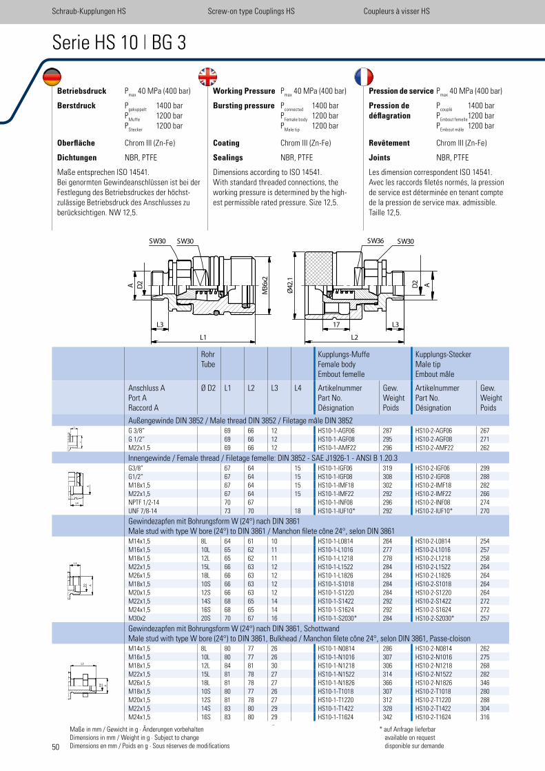
50
Betriebsdruck Pmax
40 MPa (400 bar)
Berstdruck Pgekuppelt
1400 bar P
Muffe 1200 bar
PStecker
1200 bar
Oberfläche Chrom III (Zn-Fe)
Dichtungen NBR, PTFE
Maße entsprechen ISO 14541. Bei genormten Gewindeanschlüssen ist bei der Festlegung des Betriebsdruckes der höchst-zulässige Betriebsdruck des Anschlusses zu berücksichtigen. NW 12,5.
Working Pressure Pmax
40 MPa (400 bar)
Bursting pressure Pconnected
1400 bar P
Female body 1200 bar
PMale tip
1200 bar
Coating Chrom III (Zn-Fe)
Sealings NBR, PTFE
Dimensions according to ISO 14541. With standard threaded connections, the working pressure is determined by the high-est permissible rated pressure. Size 12,5.
Pression de service Pmax
40 MPa (400 bar)
Pression de Pcouplé
1400 bar déflagration P
Embout femelle 1200 bar
PEmbout mâle
1200 bar
Revêtement Chrom III (Zn-Fe)
Joints NBR, PTFE
Les dimension correspondent ISO 14541. Avec les raccords iletés normés, la pression de service est déterminée en tenant compte de la pression de service max. admissible. Taille 12,5.
Serie HS 10 | BG 3
RohrTube
Kupplungs-MuffeFemale bodyEmbout femelle
Kupplungs-SteckerMale tipEmbout mâle
Anschluss APort ARaccord A
Ø D2 L1 L2 L3 L4 ArtikelnummerPart No.Désignation
Gew.WeightPoids
ArtikelnummerPart No.Désignation
Gew.WeightPoids
Außengewinde DIN 3852 / Male thread DIN 3852 / Filetage mâle DIN 3852G 3/8“ 69 66 12 HS10-1-AGF06 287 HS10-2-AGF06 267G 1/2“ 69 66 12 HS10-1-AGF08 295 HS10-2-AGF08 271M22x1,5 69 66 12 HS10-1-AMF22 296 HS10-2-AMF22 262
Innengewinde / Female thread / Filetage femelle: DIN 3852 - SAE J1926-1 - ANSI B 1.20.3G3/8“ 67 64 15 HS10-1-IGF06 319 HS10-2-IGF06 299G1/2“ 67 64 15 HS10-1-IGF08 308 HS10-2-IGF08 288M18x1,5 67 64 15 HS10-1-IMF18 302 HS10-2-IMF18 282M22x1,5 67 64 15 HS10-1-IMF22 292 HS10-2-IMF22 266NPTF 1/2-14 70 67 HS10-1-INF08 296 HS10-2-INF08 274UNF 7/8-14 73 70 18 HS10-1-IUF10* 292 HS10-2-IUF10* 270
Gewindezapfen mit Bohrungsform W (24°) nach DIN 3861Male stud with type W bore (24°) to DIN 3861 / Manchon ilete cône 24°, selon DIN 3861M14x1,5 8L 64 61 10 HS10-1-L0814 264 HS10-2-L0814 254M16x1,5 10L 65 62 11 HS10-1-L1016 277 HS10-2-L1016 257M18x1,5 12L 65 62 11 HS10-1-L1218 278 HS10-2-L1218 258M22x1,5 15L 66 63 12 HS10-1-L1522 284 HS10-2-L1522 264M26x1,5 18L 66 63 12 HS10-1-L1826 284 HS10-2-L1826 264M18x1,5 10S 66 63 12 HS10-1-S1018 284 HS10-2-S1018 264M20x1,5 12S 66 63 12 HS10-1-S1220 284 HS10-2-S1220 264M22x1,5 14S 68 65 14 HS10-1-S1422 292 HS10-2-S1422 272M24x1,5 16S 68 65 14 HS10-1-S1624 292 HS10-2-S1624 272M30x2 20S 70 67 16 HS10-1-S2030* 284 HS10-2-S2030* 257
Gewindezapfen mit Bohrungsform W (24°) nach DIN 3861, SchottwandMale stud with type W bore (24°) to DIN 3861, Bulkhead / Manchon ilete cône 24°, selon DIN 3861, Passe-cloisonM14x1,5 8L 80 77 26 HS10-1-N0814 286 HS10-2-N0814 262M16x1,5 10L 80 77 26 HS10-1-N1016 307 HS10-2-N1016 275M18x1,5 12L 84 81 30 HS10-1-N1218 306 HS10-2-N1218 268M22x1,5 15L 81 78 27 HS10-1-N1522 314 HS10-2-N1522 282M26x1,5 18L 81 78 27 HS10-1-N1826 366 HS10-2-N1826 346M18x1,5 10S 80 77 26 HS10-1-T1018 307 HS10-2-T1018 280M20x1,5 12S 81 78 27 HS10-1-T1220 312 HS10-2-T1220 288M22x1,5 14S 83 80 29 HS10-1-T1422 328 HS10-2-T1422 304M24x1,5 16S 83 80 29 HS10-1-T1624 342 HS10-2-T1624 316
Maße in mm / Gewicht in g · Änderungen vorbehaltenDimensions in mm / Weight in g · Subject to changeDimensions en mm / Poids en g · Sous réserves de modiications
* auf Anfrage lieferbar available on request disponible sur demande
Schraub-Kupplungen HS Screw-on type Couplings HS Coupleurs à visser HS
L3
L1
D2
A 36
Mx2
42.1
Ø
17
L2
L3
D2
A
SW30SW30 SW36 SW30
L4
A
L3
A
L3
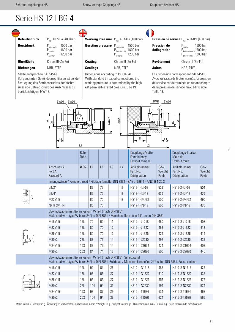
51
Betriebsdruck Pmax
40 MPa (400 bar)
Berstdruck Pgekuppelt
1500 bar P
Muffe 1600 bar
PStecker
1200 bar
Oberfläche Chrom III (Zn-Fe)
Dichtungen NBR, PTFE
Maße entsprechen ISO 14541. Bei genormten Gewindeanschlüssen ist bei der Festlegung des Betriebsdruckes der höchst-zulässige Betriebsdruck des Anschlusses zu berücksichtigen. NW 19.
Working Pressure Pmax
40 MPa (400 bar)
Bursting pressure Pconnected
1500 bar P
Female body 1600 bar
PMale tip
1200 bar
Coating Chrom III (Zn-Fe)
Sealings NBR, PTFE
Dimensions according to ISO 14541. With standard threaded connections, the working pressure is determined by the high-est permissible rated pressure. Size 19.
Pression de service Pmax
40 MPa (400 bar)
Pression de Pcouplé
1500 bar déflagration P
Embout femelle 1600 bar
PEmbout mâle
1200 bar
Revêtement Chrom III (Zn-Fe)
Joints NBR, PTFE
Les dimension correspondent ISO 14541. Avec les raccords iletés normés, la pression de service est déterminée en tenant compte de la pression de service max. admissible. Taille 19.
Serie HS 12 | BG 4
RohrTube
Kupplungs-MuffeFemale bodyEmbout femelle
Kupplungs-SteckerMale tipEmbout mâle
Anschluss APort ARaccord A
Ø D2 L1 L2 L3 L4 ArtikelnummerPart No.Désignation
Gew.WeightPoids
ArtikelnummerPart No.Désignation
Gew.WeightPoids
Innengewinde / Female thread / Filetage femelle: DIN 3852 - SAE J1926-1 - ANSI B 1.20.3
G1/2“ 86 75 19 HS12-1-IGF08 526 HS12-2-IGF08 504
G3/4“ 86 75 19 HS12-1-IGF12 636 HS12-2-IGF12 476
M22x1,5 86 75 19 HS12-1-IMF22 550 HS12-2-IMF22 490
NPTF 3/4-14 86 75 HS12-1-INF12 550 HS12-2-INF12 476
Gewindezapfen mit Bohrungsform W (24°) nach DIN 3861Male stud with type W bore (24°) to DIN 3861 / Manchon ilete cône 24°, selon DIN 3861
M18x1,5 12L 79 69 11 HS12-1-L1218 460 HS12-2-L1218 408
M22x1,5 15L 80 70 12 HS12-1-L1522 466 HS12-2-L1522 413
M26x1,5 18L 80 70 12 HS12-1-L1826 479 HS12-2-L1826 419
M30x2 22L 82 72 14 HS12-1-L2230 492 HS12-2-L2230 431
M24x1,5 16S 82 72 14 HS12-1-S1624 474 HS12-2-S1624 402
M30x2 20S 84 74 16 HS12-1-S2030 500 HS12-2-S2030 440
Gewindezapfen mit Bohrungsform W (24°) nach DIN 3861, SchottwandMale stud with type W bore (24°) to DIN 3861, Bulkhead / Manchon ilete cône 24°, selon DIN 3861, Passe-cloison
M18x1,5 12L 94 84 26 HS12-1-N1218 488 HS12-2-N1218 422
M22x1,5 15L 95 85 27 HS12-1-N1522 510 HS12-2-N1522 438
M26x1,5 18L 95 85 27 HS12-1-N1826 557 HS12-2-N1826 475
M30x2 22L 104 94 36 HS12-1-N2230 594 HS12-2-N2230 524
M24x1,5 16S 97 87 29 HS12-1-T1624 534 HS12-2-T1624 462
M30x2 20S 104 94 36 HS12-1-T2030 624 HS12-2-T2030 565
Maße in mm / Gewicht in g · Änderungen vorbehalten · Dimensions in mm / Weight in g · Subject to change · Dimensions en mm / Poids en g · Sous réserves de modiications
Schraub-Kupplungen HS Screw-on type Couplings HS Coupleurs à visser HS
HS
L3
L1
SW36 SW36
D2A 42
Mx2
L3
L2
48.5
Ø D2 A
21
SW41 SW36
L4
A
L3
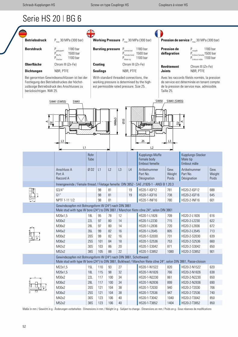
52
Betriebsdruck Pmax
30 MPa (300 bar)
Berstdruck Pgekuppelt
1180 bar P
Muffe 1500 bar
PStecker
1100 bar
Oberfläche Chrom III (Zn-Fe)
Dichtungen NBR, PTFE
Bei genormten Gewindeanschlüssen ist bei der Festlegung des Betriebsdruckes der höchst-zulässige Betriebsdruck des Anschlusses zu berücksichtigen. NW 25.
Working Pressure Pmax
30 MPa (300 bar)
Bursting pressure Pconnected
1180 bar P
Female body 1500 bar
PMale tip
1100 bar
Coating Chrom III (Zn-Fe)
Sealings NBR, PTFE
With standard threaded connections, the working pressure is determined by the high-est permissible rated pressure. Size 25.
Pression de service Pmax
30 MPa (300 bar)
Pression de Pcouplé
1180 bardéflagration P
Embout femelle 1500 bar
PEmbout mâle
1100 bar Revêtement Chrom III (Zn-Fe)Joints NBR, PTFE
Avec les raccords iletés normés, la pression de service est déterminée en tenant compte de la pression de service max. admissible.Taille 25.
Serie HS 20 | BG 6
RohrTube
Kupplungs-MuffeFemale bodyEmbout femelle
Kupplungs-SteckerMale tipEmbout mâle
Anschluss APort ARaccord A
Ø D2 L1 L2 L3 L4 ArtikelnummerPart No.Désignation
Gew.WeightPoids
ArtikelnummerPart No.Désignation
Gew.WeightPoids
Innengewinde / Female thread / Filetage femelle: DIN 3852 - SAE J1926-1 - ANSI B 1.20.3
G3/4“ 98 81 19 HS20-1-IGF12 781 HS20-2-IGF12 688
G1“ 98 81 19 HS20-1-IGF16 738 HS20-2-IGF16 645
NPTF 1-11 1/2 98 81 HS20-1-INF16 780 HS20-2-INF16 601
Gewindezapfen mit Bohrungsform W (24°) nach DIN 3861Male stud with type W bore (24°) to DIN 3861 / Manchon ilete cône 24°, selon DIN 3861
M26x1,5 18L 95 78 12 HS20-1-L1826 709 HS20-2-L1826 616
M30x2 22L 97 80 14 HS20-1-L2230 715 HS20-2-L2230 622
M36x2 28L 97 80 14 HS20-1-L2836 720 HS20-2-L2836 672
M45x2 35L 99 82 16 HS20-1-L3545 805 HS20-2-L3545 713
M30x2 20S 99 82 16 HS20-1-S2030 731 HS20-2-S2030 639
M36x2 25S 101 84 18 HS20-1-S2536 753 HS20-2-S2536 660
M42x2 30S 103 86 20 HS20-1-S3042 871 HS20-2-S3042 650
M52x2 38S 105 88 22 HS20-1-S3852 1080 HS20-2-S3852 901
Gewindezapfen mit Bohrungsform W (24°) nach DIN 3861, SchottwandMale stud with type W bore (24°) to DIN 3861, Bulkhead / Manchon ilete cône 24°, selon DIN 3861, Passe-cloison
M22x1,5 15L 110 93 27 HS20-1-N1522 820 HS20-2-N1522 620
M26x1,5 18L 115 98 32 HS20-1-N1826 766 HS20-2-N1826 638
M30x2 22L 117 100 34 HS20-1-N2230 861 HS20-2-N2230 650
M36x2 28L 117 100 34 HS20-1-N2836 899 HS20-2-N2836 690
M30x2 20S 121 104 38 HS20-1-T2030 940 HS20-2-T2030 706
M36x2 25S 121 104 38 HS20-1-T2536 947 HS20-2-T2536 740
M42x2 30S 123 106 40 HS20-1-T3042 1040 HS20-2-T3042 850
M52x2 38S 123 106 40 HS20-1-T3852 1404 HS20-2-T3852 850
Maße in mm / Gewicht in g · Änderungen vorbehalten · Dimensions in mm / Weight in g · Subject to change · Dimensions en mm / Poids en g · Sous réserves de modiications
Schraub-Kupplungen HS Screw-on type Couplings HS Coupleurs à visser HS
L4
A
L3
L1
A
D2 48
Mx3
SW41 (SW55) SW41
L3 L326
L2
SW50 SW41 (SW55)
55
�
A
D2Ø
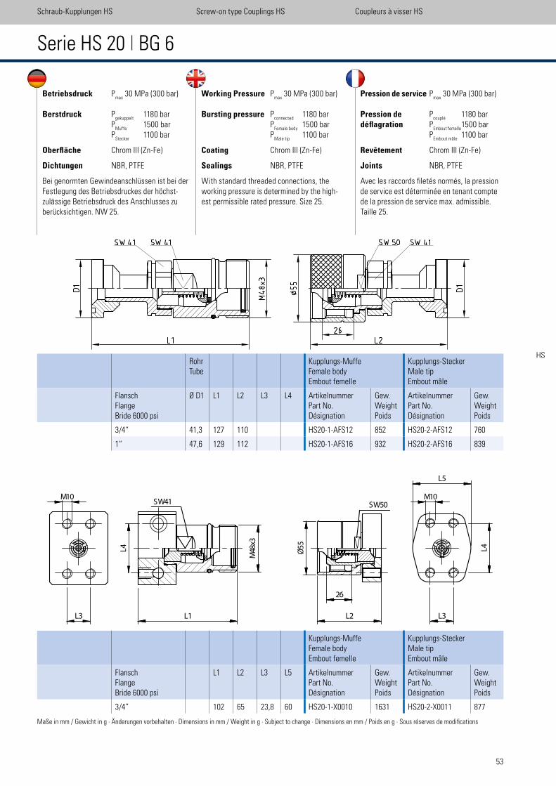
53
Betriebsdruck Pmax
30 MPa (300 bar)
Berstdruck Pgekuppelt
1180 bar P
Muffe 1500 bar
PStecker
1100 bar
Oberfläche Chrom III (Zn-Fe)
Dichtungen NBR, PTFE
Bei genormten Gewindeanschlüssen ist bei der Festlegung des Betriebsdruckes der höchst-zulässige Betriebsdruck des Anschlusses zu berücksichtigen. NW 25.
Working Pressure Pmax
30 MPa (300 bar)
Bursting pressure Pconnected
1180 bar P
Female body 1500 bar
PMale tip
1100 bar
Coating Chrom III (Zn-Fe)
Sealings NBR, PTFE
With standard threaded connections, the working pressure is determined by the high-est permissible rated pressure. Size 25.
Pression de service Pmax
30 MPa (300 bar)
Pression de Pcouplé
1180 bardéflagration P
Embout femelle 1500 bar
PEmbout mâle
1100 bar
Revêtement Chrom III (Zn-Fe)
Joints NBR, PTFE
Avec les raccords iletés normés, la pression de service est déterminée en tenant compte de la pression de service max. admissible.Taille 25.
Serie HS 20 | BG 6
RohrTube
Kupplungs-MuffeFemale bodyEmbout femelle
Kupplungs-SteckerMale tipEmbout mâle
FlanschFlangeBride 6000 psi
Ø D1 L1 L2 L3 L4 ArtikelnummerPart No.Désignation
Gew.WeightPoids
ArtikelnummerPart No.Désignation
Gew.WeightPoids
3/4“ 41,3 127 110 HS20-1-AFS12 852 HS20-2-AFS12 760
1“ 47,6 129 112 HS20-1-AFS16 932 HS20-2-AFS16 839
Maße in mm / Gewicht in g · Änderungen vorbehalten · Dimensions in mm / Weight in g · Subject to change · Dimensions en mm / Poids en g · Sous réserves de modiications
Kupplungs-MuffeFemale bodyEmbout femelle
Kupplungs-SteckerMale tipEmbout mâle
FlanschFlangeBride 6000 psi
L1 L2 L3 L5 ArtikelnummerPart No.Désignation
Gew.WeightPoids
ArtikelnummerPart No.Désignation
Gew.WeightPoids
3/4“ 102 65 23,8 60 HS20-1-X0010 1631 HS20-2-X0011 877
Schraub-Kupplungen HS Screw-on type Couplings HS Coupleurs à visser HS
HS
L3
10M
L4
L1
48
Mx3
55
Ø
26
L2 L3
L5
10M
L4
SW41SW50
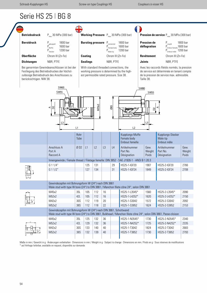
54
Betriebsdruck Pmax
30 MPa (300 bar)
Berstdruck Pgekuppelt
1800 bar P
Muffe 1600 bar
PStecker
1200 bar
Oberfläche Chrom III (Zn-Fe)
Dichtungen NBR, PTFE
Bei genormten Gewindeanschlüssen ist bei der Festlegung des Betriebsdruckes der höchst-zulässige Betriebsdruck des Anschlusses zu berücksichtigen. NW 38.
Working Pressure Pmax
30 MPa (300 bar)
Bursting pressure Pconnected
1800 bar P
Female body 1600 bar
PMale tip
1200 bar
Coating Chrom III (Zn-Fe)
Sealings NBR, PTFE
With standard threaded connections, the working pressure is determined by the high-est permissible rated pressure. Size 38.
Pression de service Pmax
30 MPa (300 bar)
Pression de Pcouplé
1800 bardéflagration P
Embout femelle 1600 bar
PEmbout mâle
1200 bar
Revêtement Chrom III (Zn-Fe)
Joints NBR, PTFE
Avec les raccords iletés normés, la pression de service est déterminée en tenant compte de la pression de service max. admissible.Taille 38.
Serie HS 25 | BG 8
RohrTube
Kupplungs-MuffeFemale bodyEmbout femelle
Kupplungs-SteckerMale tipEmbout mâle
Anschluss APort ARaccord A
Ø D2 L1 L2 L3 L4 ArtikelnummerPart No.Désignation
Gew.WeightPoids
ArtikelnummerPart No.Désignation
Gew.WeightPoids
Innengewinde / Female thread / Filetage femelle: DIN 3852 - SAE J1926-1 - ANSI B 1.20.3
G 1 1/4“ 125 131 29 HS25-1-IGF20 1907 HS25-2-IGF20 2766
G 1 1/2“ 127 134 31 HS25-1-IGF24 1849 HS25-2-IGF24 2708
Gewindezapfen mit Bohrungsform W (24°) nach DIN 3861Male stud with type W bore (24°) to DIN 3861 / Manchon ilete cône 24°, selon DIN 3861
M45x2 35L 105 112 16 HS25-1-L3545* 1560 HS25-2-L3545* 2090
M52x2 42L 105 112 16 HS25-1-L4252* 1620 HS25-2-L4252* 2150
M42x2 30S 112 119 20 HS25-1-S3042 1572 HS25-2-S3042 2092
M52x2 38S 112 118 22 HS25-1-S3852 1624 HS25-2-S3852 2153
Gewindezapfen mit Bohrungsform W (24°) nach DIN 3861, SchottwandMale stud with type W bore (24°) to DIN 3861, Bulkhead / Manchon ilete cône 24°, selon DIN 3861, Passe-cloison
M45x2 35L 125 132 36 HS25-1-N3545* 1730 HS25-2-N3545* 2340
M52x2 42L 129 132 36 HS25-1-N4252* 1725 HS25-2-N4252* 2335
M42x2 30S 133 140 40 HS25-1-T3042 1824 HS25-2-T3042 2683
M52x2 38S 132 139 40 HS25-1-T3852 1730 HS25-2-T3852 2793
Maße in mm / Gewicht in g · Änderungen vorbehalten · Dimensions in mm / Weight in g · Subject to change · Dimensions en mm / Poids en g · Sous réserves de modiications* auf Anfrage lieferbar, available on request, disponible sur demande
Schraub-Kupplungen HS Screw-on type Couplings HS Coupleurs à visser HS
D2A
L3
L1
70
Mx3
85
Ø
L3
L2
A
D2
SW55
SW65 SW80
SW55
L4
A
L3
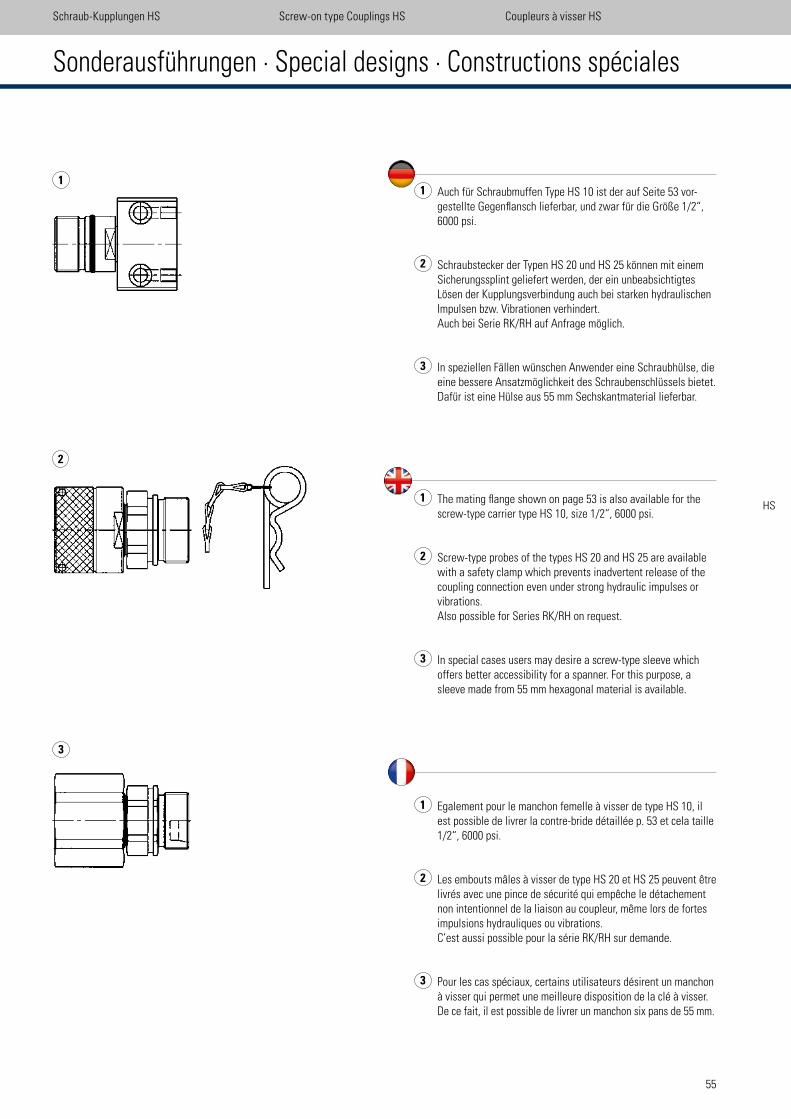
55
1 Auch für Schraubmuffen Type HS 10 ist der auf Seite 53 vor-gestellte Gegenlansch lieferbar, und zwar für die Größe 1/2“, 6000 psi.
2 Schraubstecker der Typen HS 20 und HS 25 können mit einem Sicherungssplint geliefert werden, der ein unbeabsichtigtes Lösen der Kupplungsverbindung auch bei starken hydraulischen Impulsen bzw. Vibrationen verhindert.
Auch bei Serie RK/RH auf Anfrage möglich.
3 In speziellen Fällen wünschen Anwender eine Schraubhülse, die eine bessere Ansatzmöglichkeit des Schraubenschlüssels bietet. Dafür ist eine Hülse aus 55 mm Sechskantmaterial lieferbar.
1 The mating lange shown on page 53 is also available for the screw-type carrier type HS 10, size 1/2“, 6000 psi.
2 Screw-type probes of the types HS 20 and HS 25 are available with a safety clamp which prevents inadvertent release of the coupling connection even under strong hydraulic impulses or vibrations.
Also possible for Series RK/RH on request.
3 In special cases users may desire a screw-type sleeve which offers better accessibility for a spanner. For this purpose, a sleeve made from 55 mm hexagonal material is available.
1 Egalement pour le manchon femelle à visser de type HS 10, il est possible de livrer la contre-bride détaillée p. 53 et cela taille 1/2“, 6000 psi.
2 Les embouts mâles à visser de type HS 20 et HS 25 peuvent être livrés avec une pince de sécurité qui empêche le détachement non intentionnel de la liaison au coupleur, même lors de fortes impulsions hydrauliques ou vibrations. C’est aussi possible pour la série RK/RH sur demande.
3 Pour les cas spéciaux, certains utilisateurs désirent un manchon à visser qui permet une meilleure disposition de la clé à visser. De ce fait, il est possible de livrer un manchon six pans de 55 mm.
Sonderausführungen · Special designs · Constructions spéciales
Schraub-Kupplungen HS Screw-on type Couplings HS Coupleurs à visser HS
1
2
3
HS
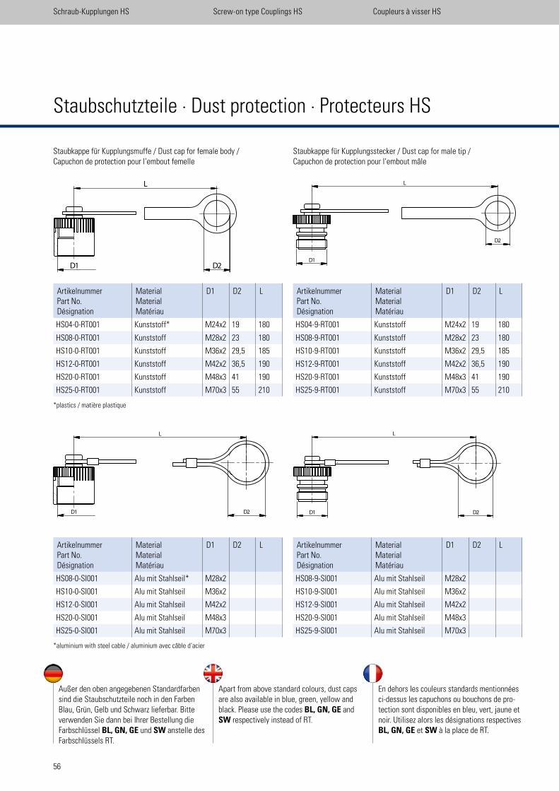
56
Staubkappe für Kupplungsstecker / Dust cap for male tip /Capuchon de protection pour l‘embout mâle
ArtikelnummerPart No.Désignation
MaterialMaterialMatériau
D1 D2 L
HS04-0-RT001 Kunststoff* M24x2 19 180
HS08-0-RT001 Kunststoff M28x2 23 180
HS10-0-RT001 Kunststoff M36x2 29,5 185
HS12-0-RT001 Kunststoff M42x2 36,5 190
HS20-0-RT001 Kunststoff M48x3 41 190
HS25-0-RT001 Kunststoff M70x3 55 210
Staubkappe für Kupplungsmuffe / Dust cap for female body / Capuchon de protection pour l‘embout femelle
*plastics / matière plastique
*aluminium with steel cable / aluminium avec câble d‘acier
ArtikelnummerPart No.Désignation
MaterialMaterialMatériau
D1 D2 L
HS04-9-RT001 Kunststoff M24x2 19 180
HS08-9-RT001 Kunststoff M28x2 23 180
HS10-9-RT001 Kunststoff M36x2 29,5 185
HS12-9-RT001 Kunststoff M42x2 36,5 190
HS20-9-RT001 Kunststoff M48x3 41 190
HS25-9-RT001 Kunststoff M70x3 55 210
Schraub-Kupplungen HS Screw-on type Couplings HS Coupleurs à visser HS
Staubschutzteile · Dust protection · Protecteurs HS
Außer den oben angegebenen Standardfarben sind die Staubschutzteile noch in den Farben Blau, Grün, Gelb und Schwarz lieferbar. Bitte verwenden Sie dann bei Ihrer Bestellung die Farbschlüssel BL, GN, GE und SW anstelle des Farbschlüssels RT.
Apart from above standard colours, dust caps are also available in blue, green, yellow and black. Please use the codes BL, GN, GE and SW respectively instead of RT.
En dehors les couleurs standards mentionnées ci-dessus les capuchons ou bouchons de pro-tection sont disponibles en bleu, vert, jaune et noir. Utilisez alors les désignations respectives BL, GN, GE et SW à la place de RT.
ArtikelnummerPart No.Désignation
MaterialMaterialMatériau
D1 D2 L
HS08-0-SI001 Alu mit Stahlseil* M28x2
HS10-0-SI001 Alu mit Stahlseil M36x2
HS12-0-SI001 Alu mit Stahlseil M42x2
HS20-0-SI001 Alu mit Stahlseil M48x3
HS25-0-SI001 Alu mit Stahlseil M70x3
ArtikelnummerPart No.Désignation
MaterialMaterialMatériau
D1 D2 L
HS08-9-SI001 Alu mit Stahlseil M28x2
HS10-9-SI001 Alu mit Stahlseil M36x2
HS12-9-SI001 Alu mit Stahlseil M42x2
HS20-9-SI001 Alu mit Stahlseil M48x3
HS25-9-SI001 Alu mit Stahlseil M70x3
L
D1 D2
L
D1 D2 D1
L
D2
D1
D2
L
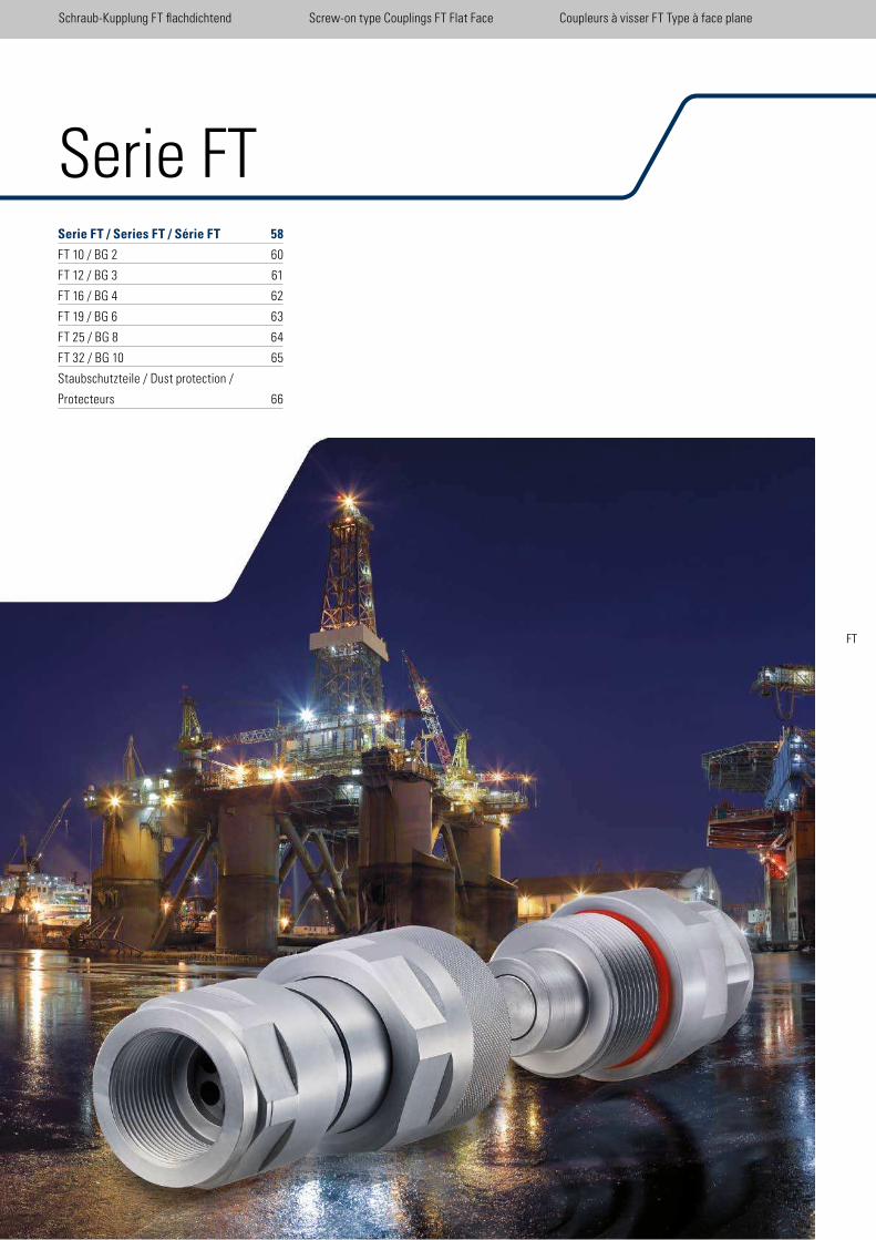
57
Serie FTSerie FT / Series FT / Série FT 58
FT 10 / BG 2 60
FT 12 / BG 3 61
FT 16 / BG 4 62
FT 19 / BG 6 63
FT 25 / BG 8 64
FT 32 / BG 10 65
Staubschutzteile / Dust protection /
Protecteurs 66
Schraub-Kupplung FT lachdichtend Screw-on type Couplings FT Flat Face Coupleurs à visser FT Type à face plane
FT
API 16 D
+ EUB
Directive
#36
58
Charakteristika · Characteristics · Caractéristiques FT
Schraub-Kupplung FT lachdichtend Screw-on type Couplings FT Flat Face Coupleurs à visser FT Type à face plane
Durchflusskennlinien: Die Kennlinien gelten nur für Kupplungen mit nicht reduzierten Anschlüssen. Medium: Hydrauliköl 36 mm2/s
Flow characteristics: The curves are only valid for couplings without reducing itting. Medium: Hydraulic Oil 36 mm2/s
Courbes de débit: Les courbes caractéristiques ne sont valables que pour des raccordements non réduits. Fluide: Huile hydraulique 36 mm2/s
FT 10
Durchsatz [l/min] / low rate / volume
0 100,0
2,0
4,0
6,0
8,0
10,0
20 30 40 50 60 70
Dru
ckdi
ffer
enz
[bar
]pr
essu
re d
iffer
ence
/ p
ress
ion
diff
éren
ce
Durchsatz [l/min] / low rate / volume
00,0
2,0
4,0
6,0
8,0
10,0
40302010 70 80 9050 60 110 120 130100 140
Dru
ckdi
ffer
enz
[bar
]pr
essu
re d
iffer
ence
/ p
ress
ion
diff
éren
ce
FT 12
Die Serie FT ist eine Schraubkupplung für sehr sichere und zuverlässige Kupplungsver-bindungen in kritischen und stark belasteten Anwendungsbereichen. Dieser Typ ist eine Weiterentwicklung unserer lachdichtenden Steckkupplung der Serie FH und verbindet die Vorteile der FH-Serie, wie z.B. die Zink-Nickel Oberläche und die umweltfreundliche Konstruktion der glatten - lachen Ventileinheiten. Dadurch ist die Kupplung äußerst leckagearm.Extreme Drücke bis 550 bar (Betriebsdruck abhängig von der Größe) können mit dieser FT Serie übertragen werden. Auch unter hohem Restdruck ist die FT-Kupplung kuppelbar.
Haupteinsatzgebiete der FT-Kupplung sind:• Öl - und Gas Industrie
> Blowout Preventer BOP• mobile und stationäre Bohranlagen• Baumaschinen• Hochdruckhydraulik
getestet nach API 16 D und EUB Directive # 36
The FT series is a screw-on type coupling for safety and reliable connections for applica-tions in critical and strong areas. This type represents the further development of our lat face FH series and combined all the advantages of the FH quick release coupling. For example the Zinc-Nickel surface and the environment-friendly construction of the lat-designed valve unit. Thereby the coupling has extremely small leakage. Operation is possible at extreme pressures up to 550 bars (working pressure depends on size). The FT series can be coupled with a high residual pressure.
The main applications of the FT-series are:• Oil- and Gas Industry
> Blowout Preventer BOP• Mobile and stationary boring installations • construction machines • High pressure hydraulic
tested acc. API 16 D and acc. EUB Directive # 36
Les coupleurs á visser de la Serie FT ont été développés pour assurer des connec-tions sûres et iables dans des conditions d´utilisations sévéres voire extremesCette série est l´évolution de notre coupleur enichable á surface plane de la Série FH et dispose des qualités de cette derniere comme par exemple le traitement de surface zinc-nickel, et sa conception respectueuse de l´environnement grace notamment á son unité de soupape á surface plane. Des pressions extremes peuvent etre suppor-tées par ce raccord de la Série FT ( jusqu´á 55 MPa-550 bar ) qui de surcroit ne tolere que de tres faibles fuites.Ce raccord á visser offre par ailleur un confort d´ utilisation optimal grace á son iletage et permet un vissage manuel même sous une pression résiduelle élevée.
Les principaux secteurs d´activités concernés:• Industrie pétroliére et gaziére > Blowout Preventer BOP• Unités de forages statiques et mobiles• Machines de construction• Domaines de l´hydraulique haute pression
Testé selon la norme API 16 D et selon la directive EUB nr 36
59
Durchsatz [l/min] / low rate / volume
00,0
1,0
2,0
3,0
4,0
Dru
ckdi
ffer
enz
[bar
]pr
essu
re d
iffer
ence
/ p
ress
ion
diff
éren
ce
FT 16
50 100 150 200 250
Schraub-Kupplung FT lachdichtend Screw-on type Couplings FT Flat Face Coupleurs à visser FT Type à face plane
FT
Durchsatz [l/min] / low rate / volume
00,0
1,0
2,0
3,0
4,0
Dru
ckdi
ffer
enz
[bar
]pr
essu
re d
iffer
ence
/ p
ress
ion
diff
éren
ce
FT 19
40302010 70 80 9050 60 110 120 130100 140 150
Durchsatz [l/min] / low rate / volume
0 24020016012080400,0
1,0
2,0
3,0
4,0
5,0
6,0
Dru
ckdi
ffer
enz
[bar
]pr
essu
re d
iffer
ence
/ p
ress
ion
diff
éren
ce
FT 25
Durchsatz [l/min] / low rate / volume
0 5004003001000,0
1,0
2,0
3,0
4,0
5,0
6,0
Dru
ckdi
ffer
enz
[bar
]pr
essu
re d
iffer
ence
/ p
ress
ion
diff
éren
ce
FT 32
200 600 700 800 900
7,0
8,0
9,0
10,0
11,0
60
Serie FT 10 | BG 2
Betriebsdruck Pmax
55 MPa (550 bar)
Berstdruck Pgekuppelt
1400 bar P
Muffe 1100 bar
PStecker
1400 bar
Oberfläche Zink-Nickel
Dichtungen NBR, PTFE
Durch die Schraubhülse können keine Kugel- eindrücke entstehen und seitliche Belastung wirkt nicht auf die Dichtelemente. Auch Rest- leckage beim entkuppeln entfällt durch die Flat-Face Ausführung. NW 10.
Working Pressure Pmax
55 MPa (550 bar)
Bursting pressure Pconnected
1400 bar P
Female body 1100 bar
PMale tip
1400 bar
Coating Zinc-Nickel
Sealings NBR, PTFE
Due to the screw sleeve design no brinelling is possible and the coupling can accommo-date some side loading. By reason of the lat-face design there is no leakage during the disconnection. Size 10.
Pression de service Pmax
55 MPa (550 bar)
Pression de Pcouplé
1400 bardéflagration P
Embout femelle 1100 bar
PEmbout mâle
1400 bar
Revêtement Zinc-Nickel
Joints NBR, PTFE
Par le manchon à visser aucun procès Brinell est possible. De plus la charge latérale ne produit pas de l’effet sur les joints. Il n’ y a pasla fuite lors du désaccouplement en raison de la construction à garniture plate. Taille 10.
Schraub-Kupplung FT lachdichtend Screw-on type Couplings FT Flat Face Coupleurs à visser FT Type à face plane
Maße in mm / Gewicht in g · Änderungen vorbehalten · Dimensions in mm / Weight in g · Subject to change · Dimensions en mm / Poids en g · Sous réserves de modiications
SW30�
SW38���
A�
L1�
L4�
L2�
M3
3x2
Ø4
2�
Ø1
9.8
�
M3
3x2
Ø3
7.8
�
17.5��� L5��
A
SW30����
Kupplungs-MuffeFemale bodyEmbout femelle
Kupplungs-SteckerMale tipEmbout mâle
Anschluss APort ARaccord A
L1 L2 L3 L4 L5 ArtikelnummerPart No.Désignation
Gew.WeightPoids
ArtikelnummerPart No.Désignation
Gew.WeightPoids
Innengewinde / Female thread / Filetage femelle: DIN 3852 - SAE J1926-1 - ANSI B 1.20.3
G 3/8“ 70 87 12,5 15 FT10-1-IGF06 360 FT10-2-IGF06 384
G 1/2“ 75 90 14 18 FT10-1-IGF08 365 FT10-2-IGF08 379
NPTF 3/8-18 75 90 FT10-1-INF06 383 FT10-2-INF06 397
NPTF 1/2-14 75 90 FT10-1-INF08 369 FT10-2-INF08 385
UNF 3/4-16 75 87 14 16 FT10-1-IUF08 373 FT10-2-IUF08 375
A�
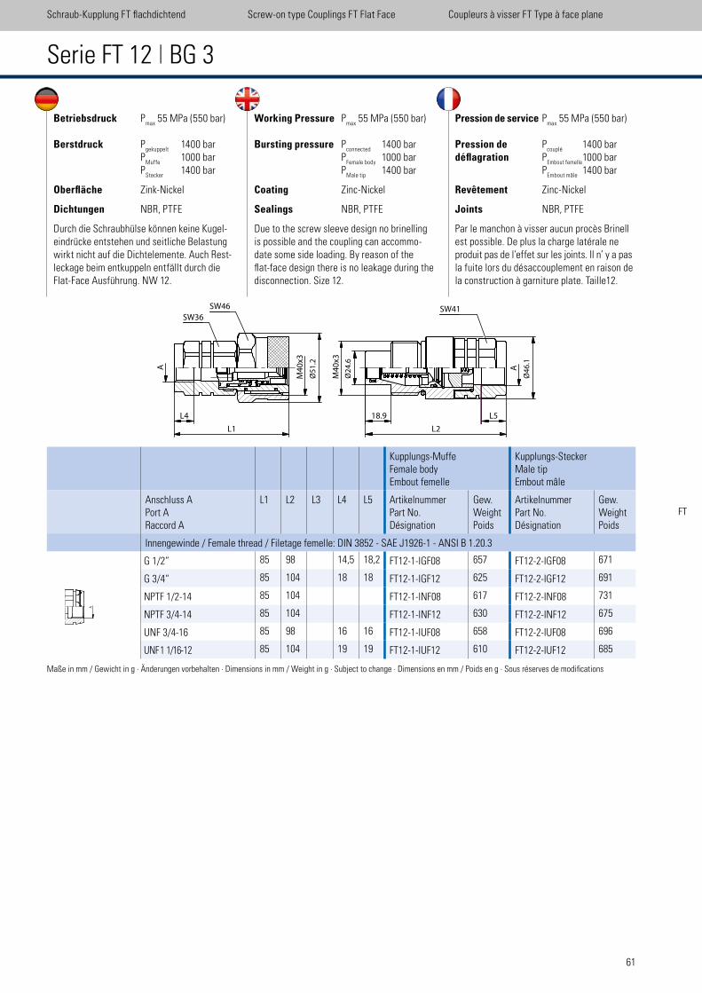
61
Betriebsdruck Pmax
55 MPa (550 bar)
Berstdruck Pgekuppelt
1400 bar P
Muffe 1000 bar
PStecker
1400 bar
Oberfläche Zink-Nickel
Dichtungen NBR, PTFE
Durch die Schraubhülse können keine Kugel- eindrücke entstehen und seitliche Belastung wirkt nicht auf die Dichtelemente. Auch Rest- leckage beim entkuppeln entfällt durch die Flat-Face Ausführung. NW 12.
Working Pressure Pmax
55 MPa (550 bar)
Bursting pressure Pconnected
1400 bar P
Female body 1000 bar
PMale tip
1400 bar
Coating Zinc-Nickel
Sealings NBR, PTFE
Due to the screw sleeve design no brinelling is possible and the coupling can accommo-date some side loading. By reason of the lat-face design there is no leakage during the disconnection. Size 12.
Pression de service Pmax
55 MPa (550 bar)
Pression de Pcouplé
1400 bardéflagration P
Embout femelle 1000 bar
PEmbout mâle
1400 bar
Revêtement Zinc-Nickel
Joints NBR, PTFE
Par le manchon à visser aucun procès Brinell est possible. De plus la charge latérale ne produit pas de l’effet sur les joints. Il n’ y a pas la fuite lors du désaccouplement en raison de la construction à garniture plate. Taille12.
Serie FT 12 | BG 3
Schraub-Kupplung FT lachdichtend Screw-on type Couplings FT Flat Face Coupleurs à visser FT Type à face plane
FT
Maße in mm / Gewicht in g · Änderungen vorbehalten · Dimensions in mm / Weight in g · Subject to change · Dimensions en mm / Poids en g · Sous réserves de modiications
Ø2
4.6
M4
0x3
Ø4
6.1
18.9L4 L5
L2
SW41
L1
M4
0x3
Ø5
1.2
SW46���
SW36
AA
Kupplungs-MuffeFemale bodyEmbout femelle
Kupplungs-SteckerMale tipEmbout mâle
Anschluss APort ARaccord A
L1 L2 L3 L4 L5 ArtikelnummerPart No.Désignation
Gew.WeightPoids
ArtikelnummerPart No.Désignation
Gew.WeightPoids
Innengewinde / Female thread / Filetage femelle: DIN 3852 - SAE J1926-1 - ANSI B 1.20.3
G 1/2” 85 98 14,5 18,2 FT12-1-IGF08 657 FT12-2-IGF08 671
G 3/4“ 85 104 18 18 FT12-1-IGF12 625 FT12-2-IGF12 691
NPTF 1/2-14 85 104 FT12-1-INF08 617 FT12-2-INF08 731
NPTF 3/4-14 85 104 FT12-1-INF12 630 FT12-2-INF12 675
UNF 3/4-16 85 98 16 16 FT12-1-IUF08 658 FT12-2-IUF08 696
UNF 1 1/16-12 85 104 19 19 FT12-1-IUF12 610 FT12-2-IUF12 685
A�
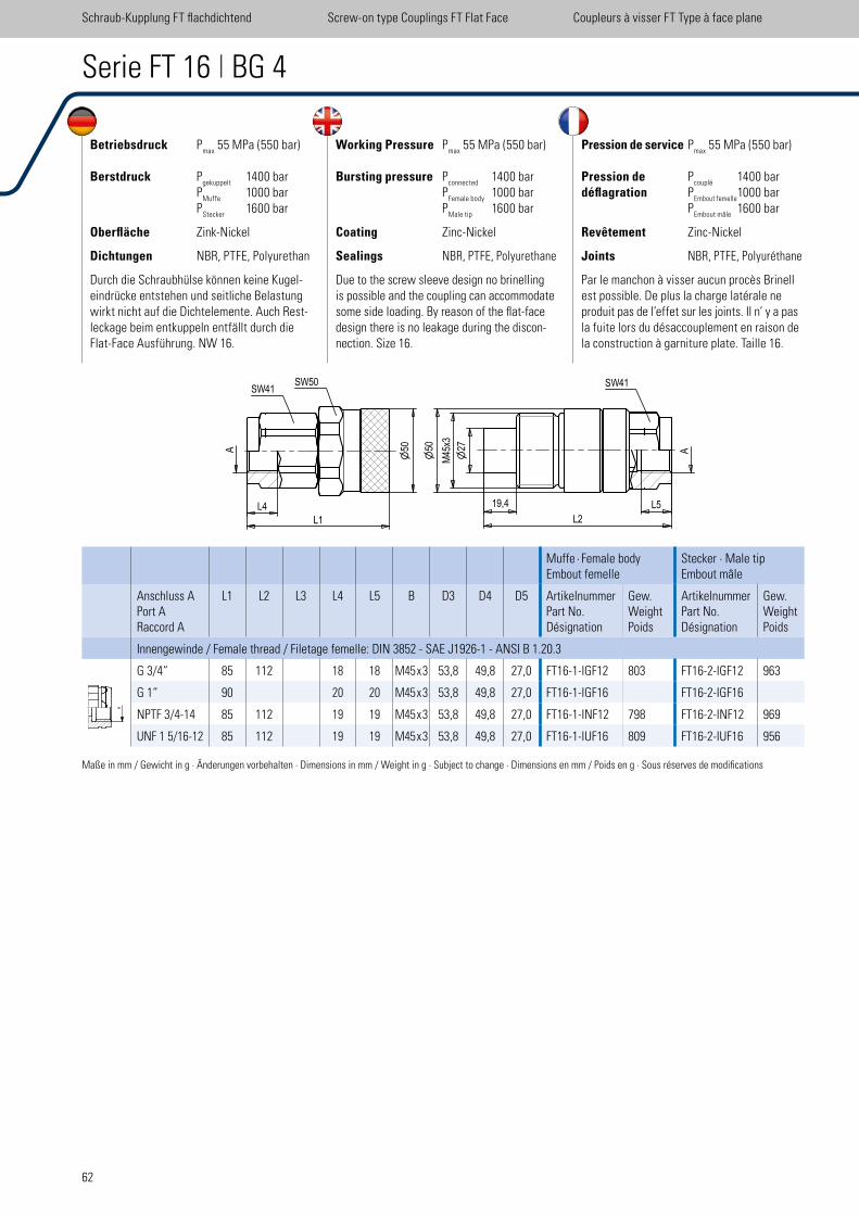
62
FT16
scale 0.55
L4
L1
SW41SW50
A 50
L5
L2
A27
M45x3
19,4
SW41
50
Betriebsdruck Pmax
55 MPa (550 bar)
Berstdruck Pgekuppelt
1400 bar P
Muffe 1000 bar
PStecker
1600 bar
Oberfläche Zink-Nickel
Dichtungen NBR, PTFE, Polyurethan
Durch die Schraubhülse können keine Kugel- eindrücke entstehen und seitliche Belastung wirkt nicht auf die Dichtelemente. Auch Rest- leckage beim entkuppeln entfällt durch die Flat-Face Ausführung. NW 16.
Working Pressure Pmax
55 MPa (550 bar)
Bursting pressure Pconnected
1400 bar P
Female body 1000 bar
PMale tip
1600 bar
Coating Zinc-Nickel
Sealings NBR, PTFE, Polyurethane
Due to the screw sleeve design no brinelling is possible and the coupling can accommodate some side loading. By reason of the lat-face design there is no leakage during the discon-nection. Size 16.
Pression de service Pmax
55 MPa (550 bar)
Pression de Pcouplé
1400 bardéflagration P
Embout femelle 1000 bar
PEmbout mâle
1600 bar
Revêtement Zinc-Nickel
Joints NBR, PTFE, Polyuréthane
Par le manchon à visser aucun procès Brinell est possible. De plus la charge latérale ne produit pas de l’effet sur les joints. Il n’ y a pas la fuite lors du désaccouplement en raison de la construction à garniture plate. Taille 16.
Serie FT 16 | BG 4
Schraub-Kupplung FT lachdichtend Screw-on type Couplings FT Flat Face Coupleurs à visser FT Type à face plane
Maße in mm / Gewicht in g · Änderungen vorbehalten · Dimensions in mm / Weight in g · Subject to change · Dimensions en mm / Poids en g · Sous réserves de modiications
Muffe · Female body Embout femelle
Stecker · Male tip Embout mâle
Anschluss APort ARaccord A
L1 L2 L3 L4 L5 B D3 D4 D5 ArtikelnummerPart No.Désignation
Gew. Weight Poids
ArtikelnummerPart No.Désignation
Gew. Weight Poids
Innengewinde / Female thread / Filetage femelle: DIN 3852 - SAE J1926-1 - ANSI B 1.20.3
G 3/4“ 85 112 18 18 M45 x 3 53,8 49,8 27,0 FT16-1-IGF12 803 FT16-2-IGF12 963
G 1“ 90 20 20 M45 x 3 53,8 49,8 27,0 FT16-1-IGF16 FT16-2-IGF16
NPTF 3/4-14 85 112 19 19 M45 x 3 53,8 49,8 27,0 FT16-1-INF12 798 FT16-2-INF12 969
UNF 1 5/16-12 85 112 19 19 M45 x 3 53,8 49,8 27,0 FT16-1-IUF16 809 FT16-2-IUF16 956
A�
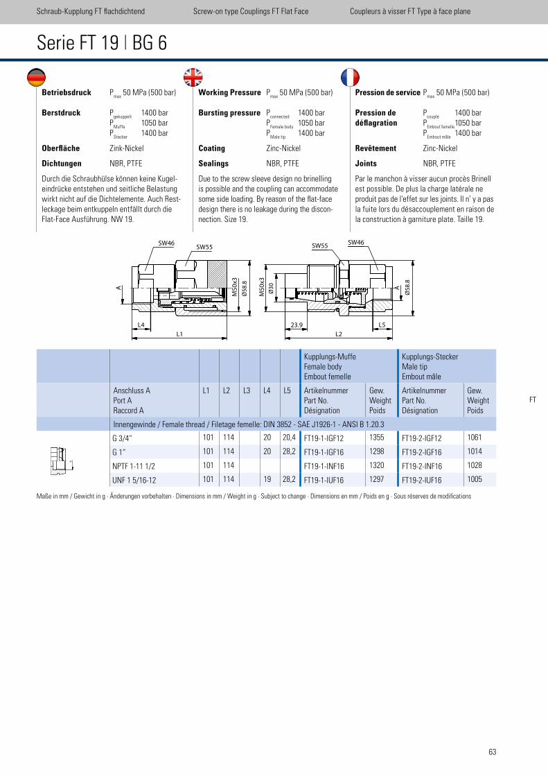
63
Betriebsdruck Pmax
50 MPa (500 bar)
Berstdruck Pgekuppelt
1400 bar P
Muffe 1050 bar
PStecker
1400 bar
Oberfläche Zink-Nickel
Dichtungen NBR, PTFE
Durch die Schraubhülse können keine Kugel- eindrücke entstehen und seitliche Belastung wirkt nicht auf die Dichtelemente. Auch Rest- leckage beim entkuppeln entfällt durch die Flat-Face Ausführung. NW 19.
Working Pressure Pmax
50 MPa (500 bar)
Bursting pressure Pconnected
1400 bar P
Female body 1050 bar
PMale tip
1400 bar
Coating Zinc-Nickel
Sealings NBR, PTFE
Due to the screw sleeve design no brinelling is possible and the coupling can accommodate some side loading. By reason of the lat-face design there is no leakage during the discon-nection. Size 19.
Pression de service Pmax
50 MPa (500 bar)
Pression de Pcouplé
1400 bardéflagration P
Embout femelle 1050 bar
PEmbout mâle
1400 bar
Revêtement Zinc-Nickel
Joints NBR, PTFE
Par le manchon à visser aucun procès Brinell est possible. De plus la charge latérale ne produit pas de l’effet sur les joints. Il n’ y a pas la fuite lors du désaccouplement en raison de la construction à garniture plate. Taille 19.
Serie FT 19 | BG 6
Maße in mm / Gewicht in g · Änderungen vorbehalten · Dimensions in mm / Weight in g · Subject to change · Dimensions en mm / Poids en g · Sous réserves de modiications
Schraub-Kupplung FT lachdichtend Screw-on type Couplings FT Flat Face Coupleurs à visser FT Type à face plane
A
L1
M5
0x3
Ø5
8.8
SW46SW55
SW46
A
Ø3
0
M5
0x3
23.9
L2
SW55
Ø5
8.8
L5L4
FT
Kupplungs-MuffeFemale bodyEmbout femelle
Kupplungs-SteckerMale tipEmbout mâle
Anschluss APort ARaccord A
L1 L2 L3 L4 L5 ArtikelnummerPart No.Désignation
Gew.WeightPoids
ArtikelnummerPart No.Désignation
Gew.WeightPoids
Innengewinde / Female thread / Filetage femelle: DIN 3852 - SAE J1926-1 - ANSI B 1.20.3
G 3/4“ 101 114 20 20,4 FT19-1-IGF12 1355 FT19-2-IGF12 1061
G 1“ 101 114 20 28,2 FT19-1-IGF16 1298 FT19-2-IGF16 1014
NPTF 1-11 1/2 101 114 FT19-1-INF16 1320 FT19-2-INF16 1028
UNF 1 5/16-12 101 114 19 28,2 FT19-1-IUF16 1297 FT19-2-IUF16 1005
A�
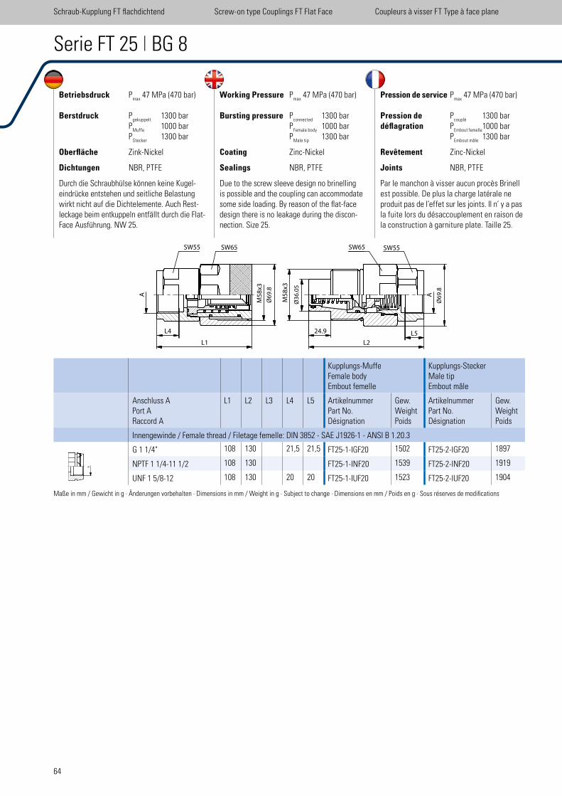
64
Betriebsdruck Pmax
47 MPa (470 bar)
Berstdruck Pgekuppelt
1300 bar P
Muffe 1000 bar
PStecker
1300 bar
Oberfläche Zink-Nickel
Dichtungen NBR, PTFE
Durch die Schraubhülse können keine Kugel- eindrücke entstehen und seitliche Belastung wirkt nicht auf die Dichtelemente. Auch Rest- leckage beim entkuppeln entfällt durch die Flat-Face Ausführung. NW 25.
Working Pressure Pmax
47 MPa (470 bar)
Bursting pressure Pconnected
1300 bar P
Female body 1000 bar
PMale tip
1300 bar
Coating Zinc-Nickel
Sealings NBR, PTFE
Due to the screw sleeve design no brinelling is possible and the coupling can accommodate some side loading. By reason of the lat-face design there is no leakage during the discon-nection. Size 25.
Pression de service Pmax
47 MPa (470 bar)
Pression de Pcouplé
1300 bardéflagration P
Embout femelle 1000 bar
PEmbout mâle
1300 bar
Revêtement Zinc-Nickel
Joints NBR, PTFE
Par le manchon à visser aucun procès Brinell est possible. De plus la charge latérale ne produit pas de l’effet sur les joints. Il n’ y a pas la fuite lors du désaccouplement en raison de la construction à garniture plate. Taille 25.
Serie FT 25 | BG 8
Schraub-Kupplung FT lachdichtend Screw-on type Couplings FT Flat Face Coupleurs à visser FT Type à face plane
Maße in mm / Gewicht in g · Änderungen vorbehalten · Dimensions in mm / Weight in g · Subject to change · Dimensions en mm / Poids en g · Sous réserves de modiications
SW55 SW65
A
24.9
L2L1
Ø3
6.0
5
M5
8x3
Ø6
9.8
A
SW65 SW55
M5
8x3
Ø6
9.8
L5L4
Kupplungs-MuffeFemale bodyEmbout femelle
Kupplungs-SteckerMale tipEmbout mâle
Anschluss APort ARaccord A
L1 L2 L3 L4 L5 ArtikelnummerPart No.Désignation
Gew.WeightPoids
ArtikelnummerPart No.Désignation
Gew.WeightPoids
Innengewinde / Female thread / Filetage femelle: DIN 3852 - SAE J1926-1 - ANSI B 1.20.3
G 1 1/4" 108 130 21,5 21,5 FT25-1-IGF20 1502 FT25-2-IGF20 1897
NPTF 1 1/4-11 1/2 108 130 FT25-1-INF20 1539 FT25-2-INF20 1919
UNF 1 5/8-12 108 130 20 20 FT25-1-IUF20 1523 FT25-2-IUF20 1904
A�
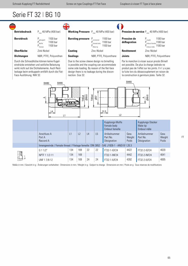
65
Betriebsdruck Pmax
40 MPa (400 bar)
Berstdruck Pgekuppelt
1100 bar P
Muffe 1100 bar
PStecker
1100 bar
Oberfläche Zink-Nickel
Dichtungen NBR, PTFE, Polyurethan
Durch die Schraubhülse können keine Kugel- eindrücke entstehen und seitliche Belastung wirkt nicht auf die Dichtelemente. Auch Rest- leckage beim entkuppeln entfällt durch die Flat-Face Ausführung. NW 32.
Working Pressure Pmax
40 MPa (400 bar)
Bursting pressure Pconnected
1100 bar P
Female body 1100 bar
PMale tip
1100 bar
Coating Zinc-Nickel
Sealings NBR, PTFE, Polyurethane
Due to the screw sleeve design no brinelling is possible and the coupling can accommodate some side loading. By reason of the lat-face design there is no leakage during the discon-nection. Size 32.
Pression de service Pmax
40 MPa (400 bar)
Pression de Pcouplé
1100 bardéflagration P
Embout femelle 1100 bar
PEmbout mâle
1100 bar
Revêtement Zinc-Nickel
Joints NBR, PTFE, Polyuréthane
Par le manchon à visser aucun procès Brinell est possible. De plus la charge latérale ne produit pas de l’effet sur les joints. Il n’ y a pas la fuite lors du désaccouplement en raison de la construction à garniture plate. Taille 32.
Serie FT 32 | BG 10
Schraub-Kupplung FT lachdichtend Screw-on type Couplings FT Flat Face Coupleurs à visser FT Type à face plane
Maße in mm / Gewicht in g · Änderungen vorbehalten · Dimensions in mm / Weight in g · Subject to change · Dimensions en mm / Poids en g · Sous réserves de modiications
FT
Kupplungs-MuffeFemale bodyEmbout femelle
Kupplungs-SteckerMale tipEmbout mâle
Anschluss APort ARaccord A
L1 L2 L4 L5 ArtikelnummerPart No.Désignation
Gew.WeightPoids
ArtikelnummerPart No.Désignation
Gew.WeightPoids
Innengewinde / Female thread / Filetage femelle: DIN 3852 - SAE J1926-1 - ANSI B 1.20.3
G 1 1/2" 134 169 22 22 FT32-1-IGF24 4422 FT32-2-IGF24 4020
NPTF 1 1/2-11 134 169 FT32-1-INF24 4442 FT32-2-INF24 4041
UNF 1 7/8-12 134 169 24 24 FT32-1-IUF24 4392 FT32-2-IUF24 4005
A�
B-B ( 0,33 )
B
FT 32
scale 0,33
SW80 SW85T
r80x4
89.8
L1
A 57
Tr8
0x4
31.5
L2
A 89.8
SW65
L4
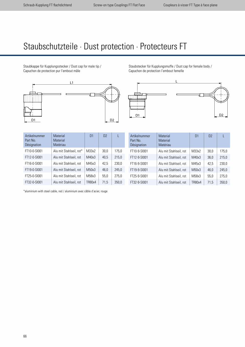
66
Staubschutzteile · Dust protection · Protecteurs FT
Staubkappe für Kupplungsstecker / Dust cap for male tip /Capuchon de protection pur l‘embout mâle
Staubstecker für Kupplungsmuffe / Dust cap for female body /Capuchon de protection l‘embout femelle
ArtikelnummerPart No.Désignation
MaterialMaterialMatériau
D1 D2 L
FT10-0-SI001 Alu mit Stahlseil, rot* M33x2 30,0 175,0
FT12-0-SI001 Alu mit Stahlseil, rot M40x3 40,5 215,0
FT16-0-SI001 Alu mit Stahlseil, rot M45x3 42,5 230,0
FT19-0-SI001 Alu mit Stahlseil, rot M50x3 46,0 245,0
FT25-0-SI001 Alu mit Stahlseil, rot M58x3 55,0 275,0
FT32-0-SI001 Alu mit Stahlseil, rot TR80x4 71,5 350,0
ArtikelnummerPart No.Désignation
MaterialMaterialMatériau
D1 D2 L
FT10-9-SI001 Alu mit Stahlseil, rot M33x2 30,0 175,0
FT12-9-SI001 Alu mit Stahlseil, rot M40x3 36,0 215,0
FT16-9-SI001 Alu mit Stahlseil, rot M45x3 42,5 230,0
FT19-9-SI001 Alu mit Stahlseil, rot M50x3 46,0 245,0
FT25-9-SI001 Alu mit Stahlseil, rot M58x3 55,0 275,0
FT32-9-SI001 Alu mit Stahlseil, rot TR80x4 71,5 350,0
*aluminium with steel cable, red / aluminium avec câble d‘acier, rouge
D1 D2
L1�
D1 D2
L�
Schraub-Kupplung FT lachdichtend Screw-on type Couplings FT Flat Face Coupleurs à visser FT Type à face plane
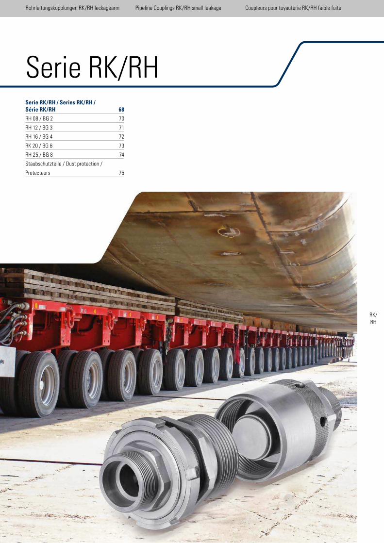
67
Serie RK/RH / Series RK/RH / Série RK/RH 68
RH 08 / BG 2 70
RH 12 / BG 3 71
RH 16 / BG 4 72
RK 20 / BG 6 73
RH 25 / BG 8 74
Staubschutzteile / Dust protection /
Protecteurs 75
Serie RK/RH
Rohrleitungskupplungen RK/RH leckagearm Pipeline Couplings RK/RH small leakage Coupleurs pour tuyauterie RK/RH faible fuite
RK/RH
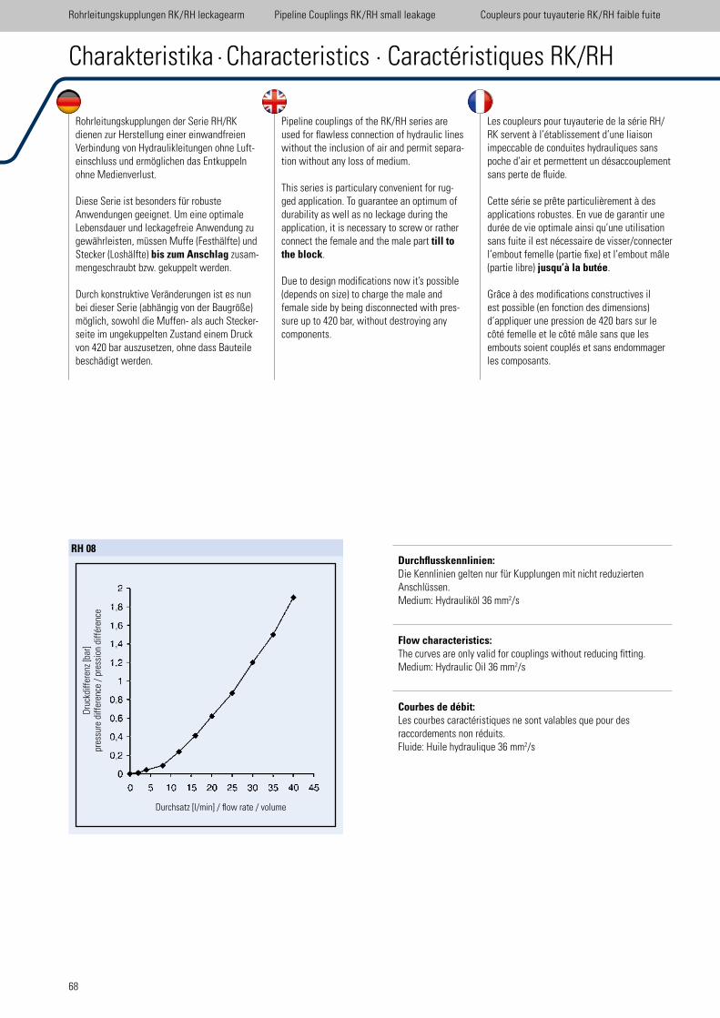
68
Rohrleitungskupplungen RK/RH leckagearm Pipeline Couplings RK/RH small leakage Coupleurs pour tuyauterie RK/RH faible fuite
Rohrleitungskupplungen der Serie RH/RK dienen zur Herstellung einer einwandfreien Verbindung von Hydraulikleitungen ohne Luft-einschluss und ermöglichen das Entkuppeln ohne Medienverlust.
Diese Serie ist besonders für robuste Anwendungen geeignet. Um eine optimale Lebensdauer und leckagefreie Anwendung zu gewährleisten, müssen Muffe (Festhälfte) und Stecker (Loshälfte) bis zum Anschlag zusam-mengeschraubt bzw. gekuppelt werden.
Durch konstruktive Veränderungen ist es nun bei dieser Serie (abhängig von der Baugröße) möglich, sowohl die Muffen- als auch Stecker-seite im ungekuppelten Zustand einem Druck von 420 bar auszusetzen, ohne dass Bauteile beschädigt werden.
Pipeline couplings of the RK/RH series are used for lawless connection of hydraulic lines without the inclusion of air and permit separa-tion without any loss of medium.
This series is particulary convenient for rug-ged application. To guarantee an optimum of durability as well as no leckage during the application, it is necessary to screw or rather connect the female and the male part till to the block.
Due to design modiications now it’s possible (depends on size) to charge the male and female side by being disconnected with pres-sure up to 420 bar, without destroying any components.
Les coupleurs pour tuyauterie de la série RH/RK servent à l’établissement d’une liaison impeccable de conduites hydrauliques sans poche d’air et permettent un désaccouplement sans perte de luide.
Cette série se prête particulièrement à des applications robustes. En vue de garantir une durée de vie optimale ainsi qu’une utilisation sans fuite il est nécessaire de visser/connecter l’embout femelle (partie ixe) et l’embout mâle (partie libre) jusqu’à la butée.
Grâce à des modiications constructives il est possible (en fonction des dimensions) d’appliquer une pression de 420 bars sur le côté femelle et le côté mâle sans que les embouts soient couplés et sans endommager les composants.
Charakteristika · Characteristics · Caractéristiques RK/RH
Durchflusskennlinien:Die Kennlinien gelten nur für Kupplungen mit nicht reduzierten Anschlüssen. Medium: Hydrauliköl 36 mm2/s
Flow characteristics: The curves are only valid for couplings without reducing itting. Medium: Hydraulic Oil 36 mm2/s
Courbes de débit: Les courbes caractéristiques ne sont valables que pour desraccordements non réduits. Fluide: Huile hydraulique 36 mm2/s
RH 08
Dru
ckdi
ffer
enz
[bar
]pr
essu
re d
iffer
ence
/ p
ress
ion
diff
éren
ce
Durchsatz [l/min] / low rate / volume
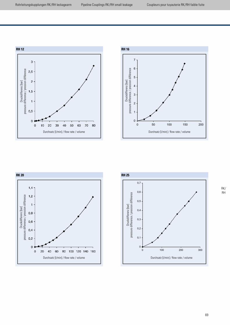
69
Rohrleitungskupplungen RK/RH leckagearm Pipeline Couplings RK/RH small leakage Coupleurs pour tuyauterie RK/RH faible fuite
RH 12
Dru
ckdi
ffer
enz
[bar
]pr
essu
re d
iffer
ence
/ p
ress
ion
diff
éren
ce
Durchsatz [l/min] / low rate / volume
RK 20
Dru
ckdi
ffer
enz
[bar
]pr
essu
re d
iffer
ence
/ p
ress
ion
diff
éren
ce
Durchsatz [l/min] / low rate / volume
RH 16
Dru
ckdi
ffer
enz
[bar
]pr
essu
re d
iffer
ence
/ p
ress
ion
diff
éren
ceDurchsatz [l/min] / low rate / volume
RH 25
Dru
ckdi
ffer
enz
[bar
]pr
essu
re d
iffer
ence
/ p
ress
ion
diff
éren
ce
Durchsatz [l/min] / low rate / volume
RK/RH
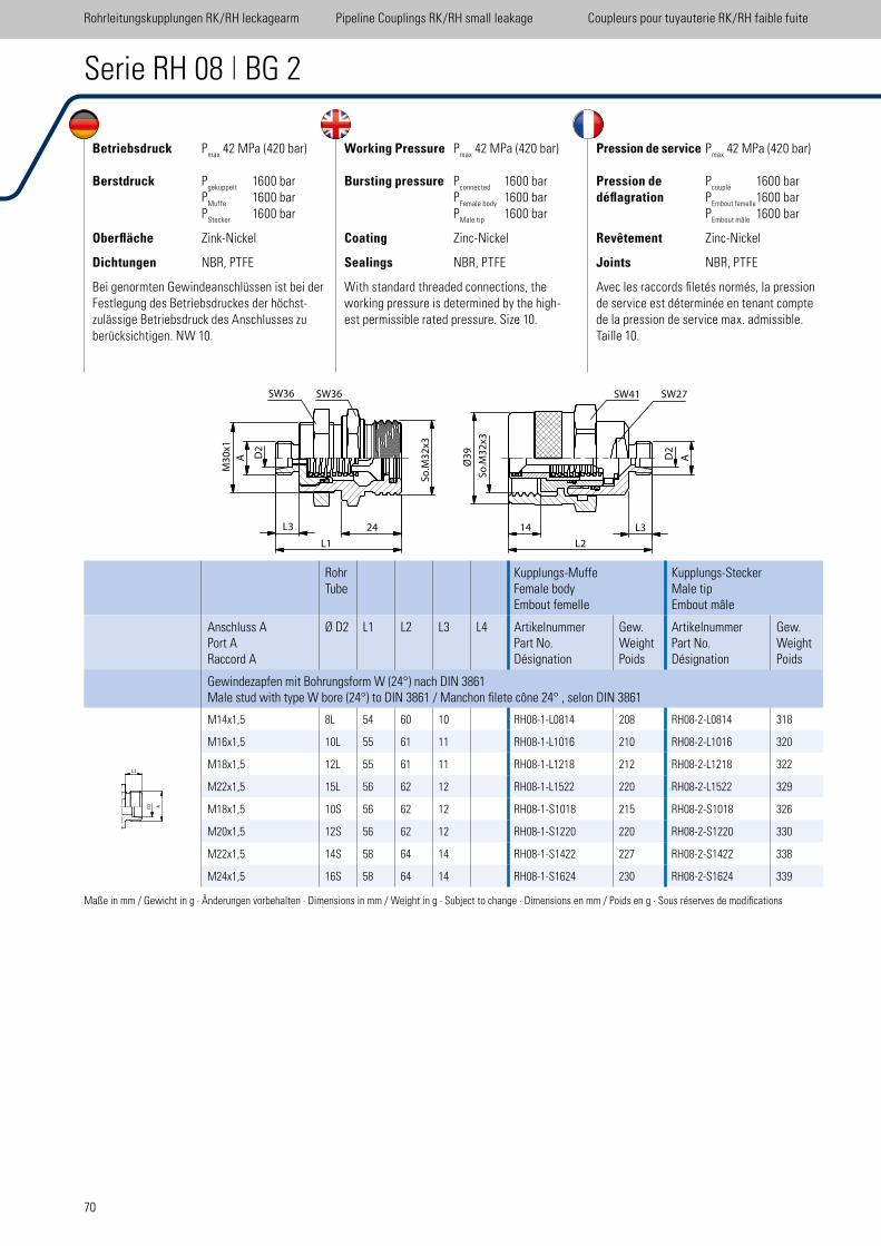
70
Betriebsdruck Pmax
42 MPa (420 bar)
Berstdruck Pgekuppelt
1600 bar P
Muffe 1600 bar
PStecker
1600 bar
Oberfläche Zink-Nickel
Dichtungen NBR, PTFE
Bei genormten Gewindeanschlüssen ist bei der Festlegung des Betriebsdruckes der höchst-zulässige Betriebsdruck des Anschlusses zu berücksichtigen. NW 10.
Working Pressure Pmax
42 MPa (420 bar)
Bursting pressure Pconnected
1600 bar P
Female body 1600 bar
PMale tip
1600 bar
Coating Zinc-Nickel
Sealings NBR, PTFE
With standard threaded connections, the working pressure is determined by the high-est permissible rated pressure. Size 10.
Pression de service Pmax
42 MPa (420 bar)
Pression de Pcouplé
1600 bardéflagration P
Embout femelle 1600 bar
PEmbout mâle
1600 bar
Revêtement Zinc-Nickel
Joints NBR, PTFE
Avec les raccords iletés normés, la pression de service est déterminée en tenant compte de la pression de service max. admissible.Taille 10.
Serie RH 08 | BG 2
RohrTube
Kupplungs-MuffeFemale bodyEmbout femelle
Kupplungs-SteckerMale tipEmbout mâle
Anschluss APort ARaccord A
Ø D2 L1 L2 L3 L4 ArtikelnummerPart No.Désignation
Gew.WeightPoids
ArtikelnummerPart No.Désignation
Gew.WeightPoids
Gewindezapfen mit Bohrungsform W (24°) nach DIN 3861Male stud with type W bore (24°) to DIN 3861 / Manchon ilete cône 24° , selon DIN 3861
M14x1,5 8L 54 60 10 RH08-1-L0814 208 RH08-2-L0814 318
M16x1,5 10L 55 61 11 RH08-1-L1016 210 RH08-2-L1016 320
M18x1,5 12L 55 61 11 RH08-1-L1218 212 RH08-2-L1218 322
M22x1,5 15L 56 62 12 RH08-1-L1522 220 RH08-2-L1522 329
M18x1,5 10S 56 62 12 RH08-1-S1018 215 RH08-2-S1018 326
M20x1,5 12S 56 62 12 RH08-1-S1220 220 RH08-2-S1220 330
M22x1,5 14S 58 64 14 RH08-1-S1422 227 RH08-2-S1422 338
M24x1,5 16S 58 64 14 RH08-1-S1624 230 RH08-2-S1624 339
Maße in mm / Gewicht in g · Änderungen vorbehalten · Dimensions in mm / Weight in g · Subject to change · Dimensions en mm / Poids en g · Sous réserves de modiications
Rohrleitungskupplungen RK/RH leckagearm Pipeline Couplings RK/RH small leakage Coupleurs pour tuyauterie RK/RH faible fuite
A
L3
L2
14 L3
AD2
Ø3
9
So
.M3
2x3
So
.M3
2x3
L3
L1
M3
0x1
�
A D2
SW36SW36 SW36 SW27
26
SW41
24
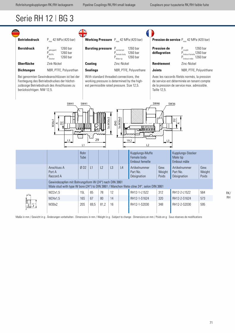
71
Betriebsdruck Pmax
42 MPa (420 bar)
Berstdruck Pgekuppelt
1260 bar P
Muffe 1260 bar
PStecker
1260 bar
Oberfläche Zink-Nickel
Dichtungen NBR, PTFE, Polyurethan
Bei genormten Gewindeanschlüssen ist bei der Festlegung des Betriebsdruckes der höchst-zulässige Betriebsdruck des Anschlusses zu berücksichtigen. NW 12,5.
Working Pressure Pmax
42 MPa (420 bar)
Bursting pressure Pconnected
1260 bar P
Female body 1260 bar
PMale tip
1260 bar
Coating Zinc-Nickel
Sealings NBR, PTFE, Polyurethane
With standard threaded connections, the working pressure is determined by the high-est permissible rated pressure. Size 12,5.
Pression de service Pmax
42 MPa (420 bar)
Pression de Pcouplé
1260 bardéflagration P
Embout femelle 1260 bar
PEmbout mâle
1260 bar
Revêtement Zinc-Nickel
Joints NBR, PTFE, Polyuréthane
Avec les raccords iletés normés, la pression de service est déterminée en tenant compte de la pression de service max. admissible.Taille 12,5.
Serie RH 12 | BG 3
RohrTube
Kupplungs-MuffeFemale bodyEmbout femelle
Kupplungs-SteckerMale tipEmbout mâle
Anschluss APort ARaccord A
Ø D2 L1 L2 L3 L4 ArtikelnummerPart No.Désignation
Gew.WeightPoids
ArtikelnummerPart No.Désignation
Gew.WeightPoids
Gewindezapfen mit Bohrungsform W (24°) nach DIN 3861Male stud with type W bore (24°) to DIN 3861 / Manchon ilete cône 24°, selon DIN 3861
M22x1,5 15L 65 78 12 RH12-1-L1522 312 RH12-2-L1522 564
M24x1,5 16S 67 80 14 RH12-1-S1624 320 RH12-2-S1624 573
M30x2 20S 69,5 81,2 16 RH12-1-S2030 348 RH12-2-S2030 595
Maße in mm / Gewicht in g · Änderungen vorbehalten · Dimensions in mm / Weight in g · Subject to change · Dimensions en mm / Poids en g · Sous réserves de modiications
Rohrleitungskupplungen RK/RH leckagearm Pipeline Couplings RK/RH small leakage Coupleurs pour tuyauterie RK/RH faible fuite
RK/RH
SW41
M3
6x1
�
L3
L1
A D2
SW41
So
.M3
6x3
L2
19.2 L3
Ø4
5
So
.M3
6x3
SW46 SW36
D2
A
��29
A
L3
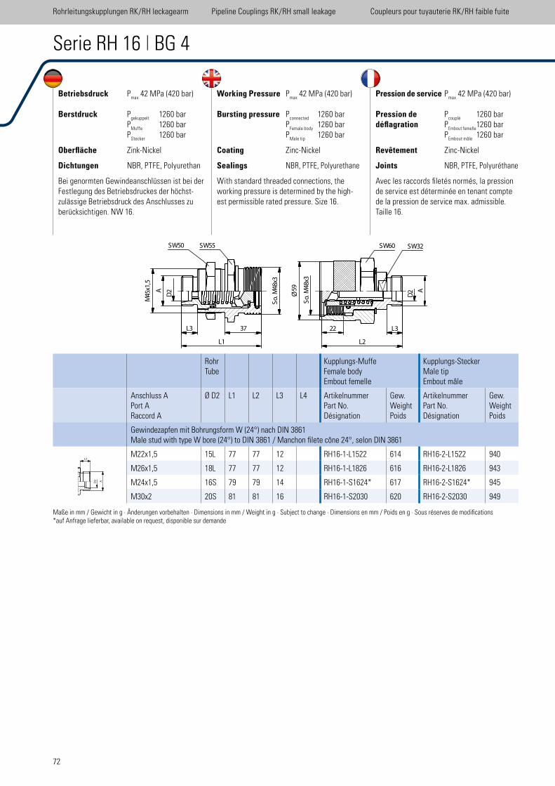
72
Serie RH 16 | BG 4
RohrTube
Kupplungs-MuffeFemale bodyEmbout femelle
Kupplungs-SteckerMale tipEmbout mâle
Anschluss APort ARaccord A
Ø D2 L1 L2 L3 L4 ArtikelnummerPart No.Désignation
Gew.WeightPoids
ArtikelnummerPart No.Désignation
Gew.WeightPoids
Gewindezapfen mit Bohrungsform W (24°) nach DIN 3861Male stud with type W bore (24°) to DIN 3861 / Manchon ilete cône 24°, selon DIN 3861
M22x1,5 15L 77 77 12 RH16-1-L1522 614 RH16-2-L1522 940
M26x1,5 18L 77 77 12 RH16-1-L1826 616 RH16-2-L1826 943
M24x1,5 16S 79 79 14 RH16-1-S1624* 617 RH16-2-S1624* 945
M30x2 20S 81 81 16 RH16-1-S2030 620 RH16-2-S2030 949
Maße in mm / Gewicht in g · Änderungen vorbehalten · Dimensions in mm / Weight in g · Subject to change · Dimensions en mm / Poids en g · Sous réserves de modiications*auf Anfrage lieferbar, available on request, disponible sur demande
Betriebsdruck Pmax
42 MPa (420 bar)
Berstdruck Pgekuppelt
1260 bar P
Muffe 1260 bar
PStecker
1260 bar
Oberfläche Zink-Nickel
Dichtungen NBR, PTFE, Polyurethan
Bei genormten Gewindeanschlüssen ist bei der Festlegung des Betriebsdruckes der höchst-zulässige Betriebsdruck des Anschlusses zu berücksichtigen. NW 16.
Working Pressure Pmax
42 MPa (420 bar)
Bursting pressure Pconnected
1260 bar P
Female body 1260 bar
PMale tip
1260 bar
Coating Zinc-Nickel
Sealings NBR, PTFE, Polyurethane
With standard threaded connections, the working pressure is determined by the high-est permissible rated pressure. Size 16.
Pression de service Pmax
42 MPa (420 bar)
Pression de Pcouplé
1260 bardéflagration P
Embout femelle 1260 bar
PEmbout mâle
1260 bar
Revêtement Zinc-Nickel
Joints NBR, PTFE, Polyuréthane
Avec les raccords iletés normés, la pression de service est déterminée en tenant compte de la pression de service max. admissible.Taille 16.
Rohrleitungskupplungen RK/RH leckagearm Pipeline Couplings RK/RH small leakage Coupleurs pour tuyauterie RK/RH faible fuite
D2A
45
Mx1
,5
48
So
. M
x3
L3
L1
SW50 SW55
22
L2
L3
A
D2
SW60 SW32
59
�
So
. M
48
x3
37
Ø
A
L3
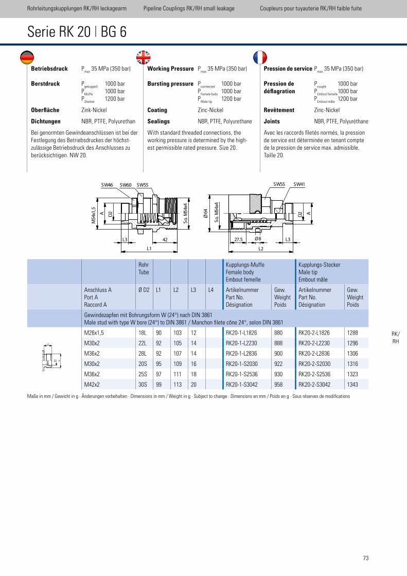
73
Serie RK 20 | BG 6
RohrTube
Kupplungs-MuffeFemale bodyEmbout femelle
Kupplungs-SteckerMale tipEmbout mâle
Anschluss APort ARaccord A
Ø D2 L1 L2 L3 L4 ArtikelnummerPart No.Désignation
Gew.WeightPoids
ArtikelnummerPart No.Désignation
Gew.WeightPoids
Gewindezapfen mit Bohrungsform W (24°) nach DIN 3861Male stud with type W bore (24°) to DIN 3861 / Manchon ilete cône 24°, selon DIN 3861
M26x1,5 18L 90 103 12 RK20-1-L1826 880 RK20-2-L1826 1288
M30x2 22L 92 105 14 RK20-1-L2230 888 RK20-2-L2230 1296
M36x2 28L 92 107 14 RK20-1-L2836 900 RK20-2-L2836 1306
M30x2 20S 95 109 16 RK20-1-S2030 922 RK20-2-S2030 1316
M36x2 25S 97 111 18 RK20-1-S2536 930 RK20-2-S2536 1323
M42x2 30S 99 113 20 RK20-1-S3042 958 RK20-2-S3042 1343
Maße in mm / Gewicht in g · Änderungen vorbehalten · Dimensions in mm / Weight in g · Subject to change · Dimensions en mm / Poids en g · Sous réserves de modiications
Betriebsdruck Pmax
35 MPa (350 bar)
Berstdruck Pgekuppelt
1000 bar P
Muffe 1000 bar
PStecker
1200 bar
Oberfläche Zink-Nickel
Dichtungen NBR, PTFE, Polyurethan
Bei genormten Gewindeanschlüssen ist bei der Festlegung des Betriebsdruckes der höchst-zulässige Betriebsdruck des Anschlusses zu berücksichtigen. NW 20.
Working Pressure Pmax
35 MPa (350 bar)
Bursting pressure Pconnected
1000 bar P
Female body 1000 bar
PMale tip
1200 bar
Coating Zinc-Nickel
Sealings NBR, PTFE, Polyurethane
With standard threaded connections, the working pressure is determined by the high-est permissible rated pressure. Size 20.
Pression de service Pmax
35 MPa (350 bar)
Pression de Pcouplé
1000 bardéflagration P
Embout femelle 1000 bar
PEmbout mâle
1200 bar
Revêtement Zinc-Nickel
Joints NBR, PTFE, Polyuréthane
Avec les raccords iletés normés, la pression de service est déterminée en tenant compte de la pression de service max. admissible.Taille 20.
Rohrleitungskupplungen RK/RH leckagearm Pipeline Couplings RK/RH small leakage Coupleurs pour tuyauterie RK/RH faible fuite
RK/RH
SW46 SW60 SW55 SW55 SW41
D2A
54
x1,5
L3
L1
64
�
54
So
. M
x4
So
. M
54
x4
27.5 8� L3
L2
D2 A
42
Ø
M
Ø
A
L3
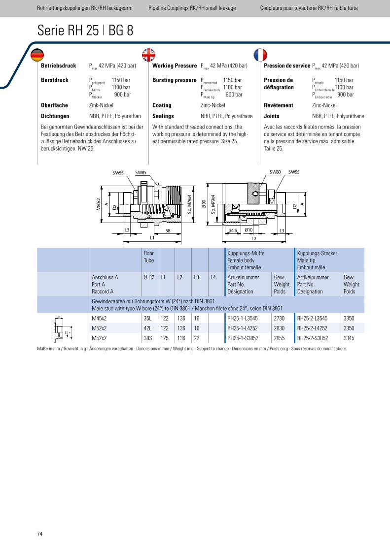
74
Serie RH 25 | BG 8
RohrTube
Kupplungs-MuffeFemale bodyEmbout femelle
Kupplungs-SteckerMale tipEmbout mâle
Anschluss APort ARaccord A
Ø D2 L1 L2 L3 L4 ArtikelnummerPart No.Désignation
Gew.WeightPoids
ArtikelnummerPart No.Désignation
Gew.WeightPoids
Gewindezapfen mit Bohrungsform W (24°) nach DIN 3861Male stud with type W bore (24°) to DIN 3861 / Manchon ilete cône 24°, selon DIN 3861
M45x2 35L 122 136 16 RH25-1-L3545 2730 RH25-2-L3545 3350
M52x2 42L 122 136 16 RH25-1-L4252 2830 RH25-2-L4252 3350
M52x2 38S 125 136 22 RH25-1-S3852 2855 RH25-2-S3852 3345
Maße in mm / Gewicht in g · Änderungen vorbehalten · Dimensions in mm / Weight in g · Subject to change · Dimensions en mm / Poids en g · Sous réserves de modiications
Betriebsdruck Pmax
42 MPa (420 bar)
Berstdruck Pgekuppelt
1150 bar P
Muffe 1100 bar
PStecker
900 bar
Oberfläche Zink-Nickel
Dichtungen NBR, PTFE, Polyurethan
Bei genormten Gewindeanschlüssen ist bei der Festlegung des Betriebsdruckes der höchst-zulässige Betriebsdruck des Anschlusses zu berücksichtigen. NW 25.
Working Pressure Pmax
42 MPa (420 bar)
Bursting pressure Pconnected
1150 bar P
Female body 1100 bar
PMale tip
900 bar
Coating Zinc-Nickel
Sealings NBR, PTFE, Polyurethane
With standard threaded connections, the working pressure is determined by the high-est permissible rated pressure. Size 25.
Pression de service Pmax
42 MPa (420 bar)
Pression de Pcouplé
1150 bardéflagration P
Embout femelle 1100 bar
PEmbout mâle
900 bar
Revêtement Zinc-Nickel
Joints NBR, PTFE, Polyuréthane
Avec les raccords iletés normés, la pression de service est déterminée en tenant compte de la pression de service max. admissible. Taille 25.
Rohrleitungskupplungen RK/RH leckagearm Pipeline Couplings RK/RH small leakage Coupleurs pour tuyauterie RK/RH faible fuite
SW55 SW85
80
Mx2
A
D2
L3
L1
79
So
. M
x4
90
�
So
. M
79
x4
10�34.5 L3
L2
A
D2
SW80 SW55
58
Ø
Ø
A
L3
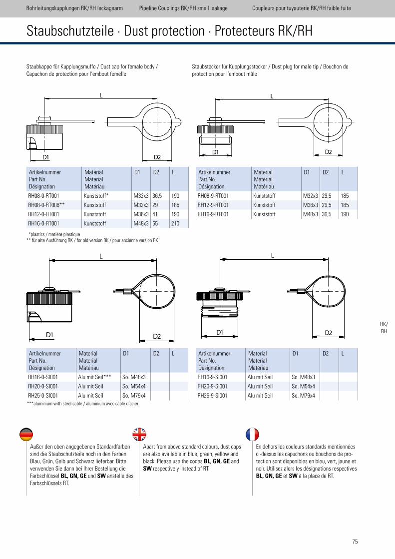
75
Staubstecker für Kupplungsstecker / Dust plug for male tip / Bouchon de protection pour l‘embout mâle
ArtikelnummerPart No.Désignation
MaterialMaterialMatériau
D1 D2 L
RH08-0-RT001 Kunststoff* M32x3 36,5 190
RH08-0-RT006** Kunststoff M32x3 29 185
RH12-0-RT001 Kunststoff M36x3 41 190
RH16-0-RT001 Kunststoff M48x3 55 210
ArtikelnummerPart No.Désignation
MaterialMaterialMatériau
D1 D2 L
RH16-0-SI001 Alu mit Seil*** So. M48x3
RH20-0-SI001 Alu mit Seil So. M54x4
RH25-0-SI001 Alu mit Seil So. M79x4
Staubkappe für Kupplungsmuffe / Dust cap for female body / Capuchon de protection pour l‘embout femelle
ArtikelnummerPart No.Désignation
MaterialMaterialMatériau
D1 D2 L
RH08-9-RT001 Kunststoff M32x3 29,5 185
RH12-9-RT001 Kunststoff M36x3 29,5 185
RH16-9-RT001 Kunststoff M48x3 36,5 190
ArtikelnummerPart No.Désignation
MaterialMaterialMatériau
D1 D2 L
RH16-9-SI001 Alu mit Seil So. M48x3
RH20-9-SI001 Alu mit Seil So. M54x4
RH25-9-SI001 Alu mit Seil So. M79x4
Rohrleitungskupplungen RK/RH leckagearm Pipeline Couplings RK/RH small leakage Coupleurs pour tuyauterie RK/RH faible fuite
Staubschutzteile · Dust protection · Protecteurs RK/RH
Außer den oben angegebenen Standardfarben sind die Staubschutzteile noch in den Farben Blau, Grün, Gelb und Schwarz lieferbar. Bitte verwenden Sie dann bei Ihrer Bestellung die Farbschlüssel BL, GN, GE und SW anstelle des Farbschlüssels RT.
Apart from above standard colours, dust caps are also available in blue, green, yellow and black. Please use the codes BL, GN, GE and SW respectively instead of RT.
En dehors les couleurs standards mentionnées ci-dessus les capuchons ou bouchons de pro-tection sont disponibles en bleu, vert, jaune et noir. Utilisez alors les désignations respectives BL, GN, GE et SW à la place de RT.
*plastics / matière plastique ** für alte Ausführung RK / for old version RK / pour ancienne version RK
***aluminium with steel cable / aluminium avec câble d‘acier
RK/RH
L
D2D1
L
D2D1
D1 D2
L
D1 D2
L

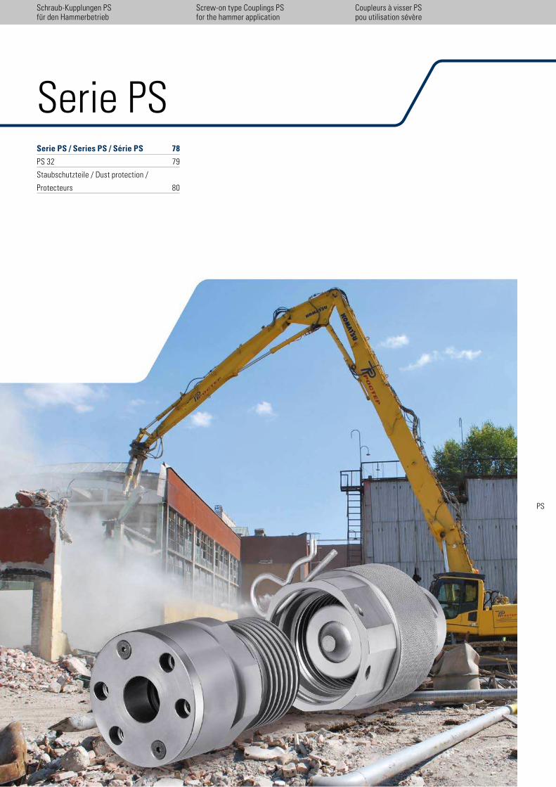
77
Serie PSSerie PS / Series PS / Série PS 78
PS 32 79
Staubschutzteile / Dust protection /
Protecteurs 80
Schraub-Kupplungen PS für den Hammerbetrieb
Coupleurs à visser PS pou utilisation sévère
Screw-on type Couplings PSfor the hammer application
PS
patented
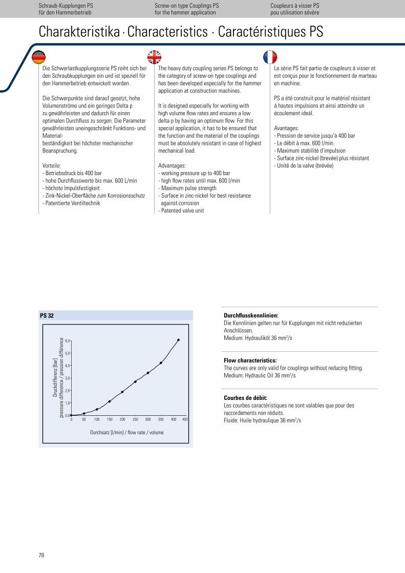
78
Durchsatz [l/min] / low rate / volume
0 450400350300250200150100500,0
2,0
1,0
3,0
5,0
4,0
6,0
Dru
ckdi
ffer
enz
[bar
]pr
essu
re d
iffer
ence
/ p
ress
ion
diff
éren
ce
PS 32
Die Schwerlastkupplungsserie PS reiht sich bei den Schraubkupplungen ein und ist speziell für den Hammerbetrieb entwickelt worden.
Die Schwerpunkte sind darauf gesetzt, hohe Volumenströme und ein geringes Delta p zu gewährleisten und dadurch für einen optimalen Durchluss zu sorgen. Die Parameter gewährleisten uneingeschränkt Funktions- und Material- beständigkeit bei höchster mechanischer Beanspruchung.
Vorteile:- Betriebsdruck bis 400 bar- hohe Durchlusswerte bis max. 600 L/min- höchste Impulsfestigkeit- Zink-Nickel-Oberläche zum Korrosionsschutz- Patentierte Ventiltechnik
The heavy duty coupling series PS belongs to the category of screw-on type couplings and has been developed especially for the hammer application at construction machines.
It is designed especially for working with high volume low rates and ensures a low delta p by having an optimum low. For this special application, it has to be ensured that the function and the material of the couplings must be absolutely resistant in case of highest mechanical load.
Advantages:- working pressure up to 400 bar- high low rates until max. 600 l/min- Maximum pulse strength- Surface in zinc-nickel for best resistance against corrosion- Patented valve unit
La série PS fait partie de coupleurs à visser et est conçus pour le fonctionnement de marteauen machine.
PS a été construit pour le matériel résistant à hautes impulsions et ainsi atteindre un écoulement ideál.
Avantages:- Pression de service jusqu’à 400 bar- Le débit à max. 600 l/min.- Maximum stabilité d’impulsion- Surface zinc-nickel (brevée) plus résistant- Unité de la valve (brévée)
Charakteristika · Characteristics · Caractéristiques PS
Schraub-Kupplungen PS für den Hammerbetrieb
Coupleurs à visser PS pou utilisation sévère
Screw-on type Couplings PSfor the hammer application
Durchflusskennlinien:Die Kennlinien gelten nur für Kupplungen mit nicht reduzierten Anschlüssen. Medium: Hydrauliköl 36 mm2/s
Flow characteristics: The curves are only valid for couplings without reducing itting. Medium: Hydraulic Oil 36 mm2/s
Courbes de débit: Les courbes caractéristiques ne sont valables que pour desraccordements non réduits. Fluide: Huile hydraulique 36 mm2/s
patented
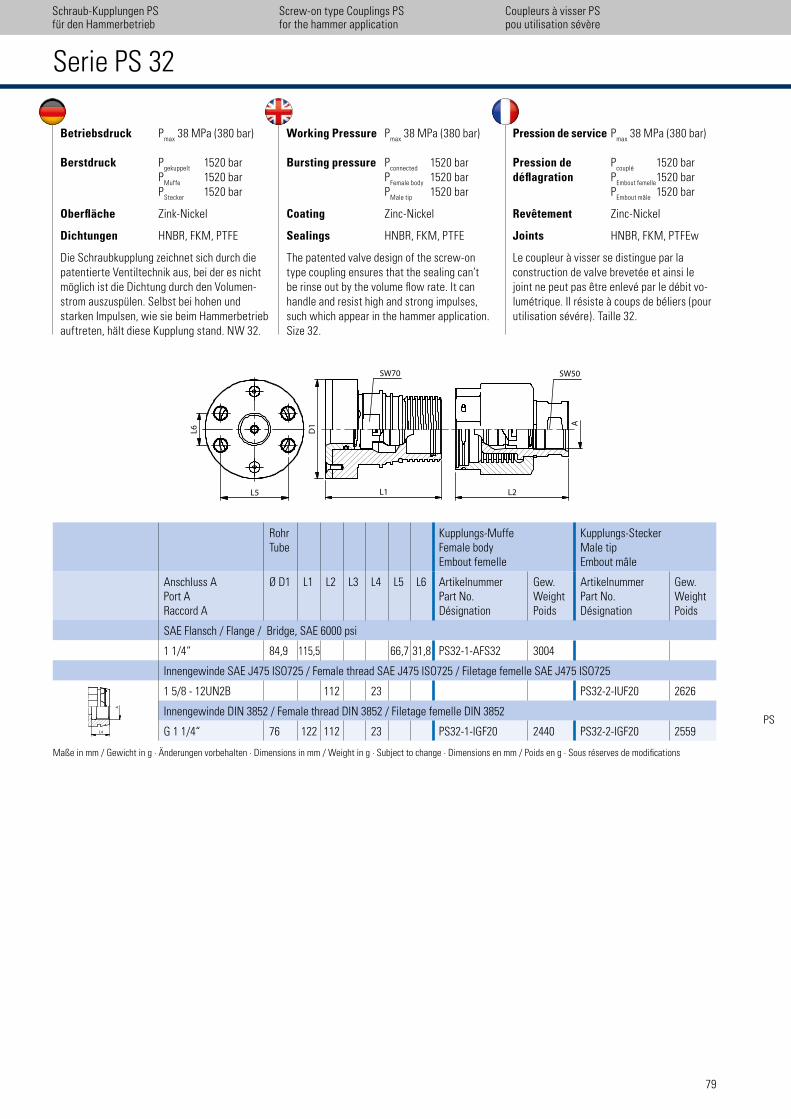
79
Schraub-Kupplungen PS für den Hammerbetrieb
Coupleurs à visser PS pou utilisation sévère
Screw-on type Couplings PSfor the hammer application
Serie PS 32
RohrTube
Kupplungs-MuffeFemale bodyEmbout femelle
Kupplungs-SteckerMale tipEmbout mâle
Anschluss APort ARaccord A
Ø D1 L1 L2 L3 L4 L5 L6 ArtikelnummerPart No.Désignation
Gew.WeightPoids
ArtikelnummerPart No.Désignation
Gew.WeightPoids
SAE Flansch / Flange / Bridge, SAE 6000 psi
1 1/4“ 84,9 115,5 66,7 31,8 PS32-1-AFS32 3004
Innengewinde SAE J475 ISO725 / Female thread SAE J475 ISO725 / Filetage femelle SAE J475 ISO725
1 5/8 - 12UN2B 112 23 PS32-2-IUF20 2626
Innengewinde DIN 3852 / Female thread DIN 3852 / Filetage femelle DIN 3852
G 1 1/4“ 76 122 112 23 PS32-1-IGF20 2440 PS32-2-IGF20 2559
Maße in mm / Gewicht in g · Änderungen vorbehalten · Dimensions in mm / Weight in g · Subject to change · Dimensions en mm / Poids en g · Sous réserves de modiications
Betriebsdruck Pmax
38 MPa (380 bar)
Berstdruck Pgekuppelt
1520 bar P
Muffe 1520 bar
PStecker
1520 bar
Oberfläche Zink-Nickel
Dichtungen HNBR, FKM, PTFE
Die Schraubkupplung zeichnet sich durch die patentierte Ventiltechnik aus, bei der es nicht möglich ist die Dichtung durch den Volumen-strom auszuspülen. Selbst bei hohen und starken Impulsen, wie sie beim Hammerbetrieb auftreten, hält diese Kupplung stand. NW 32.
Working Pressure Pmax
38 MPa (380 bar)
Bursting pressure Pconnected
1520 bar P
Female body 1520 bar
PMale tip
1520 bar
Coating Zinc-Nickel
Sealings HNBR, FKM, PTFE
The patented valve design of the screw-on type coupling ensures that the sealing can’t be rinse out by the volume low rate. It can handle and resist high and strong impulses, such which appear in the hammer application. Size 32.
Pression de service Pmax
38 MPa (380 bar)
Pression de Pcouplé
1520 bardéflagration P
Embout femelle 1520 bar
PEmbout mâle
1520 bar
Revêtement Zinc-Nickel
Joints HNBR, FKM, PTFEw
Le coupleur à visser se distingue par la construction de valve brevetée et ainsi le joint ne peut pas être enlevé par le débit vo-lumétrique. Il résiste à coups de béliers (pour utilisation sévére). Taille 32.
PS
L2L1
A
SW70 SW50
L6
L5�
D1
L4
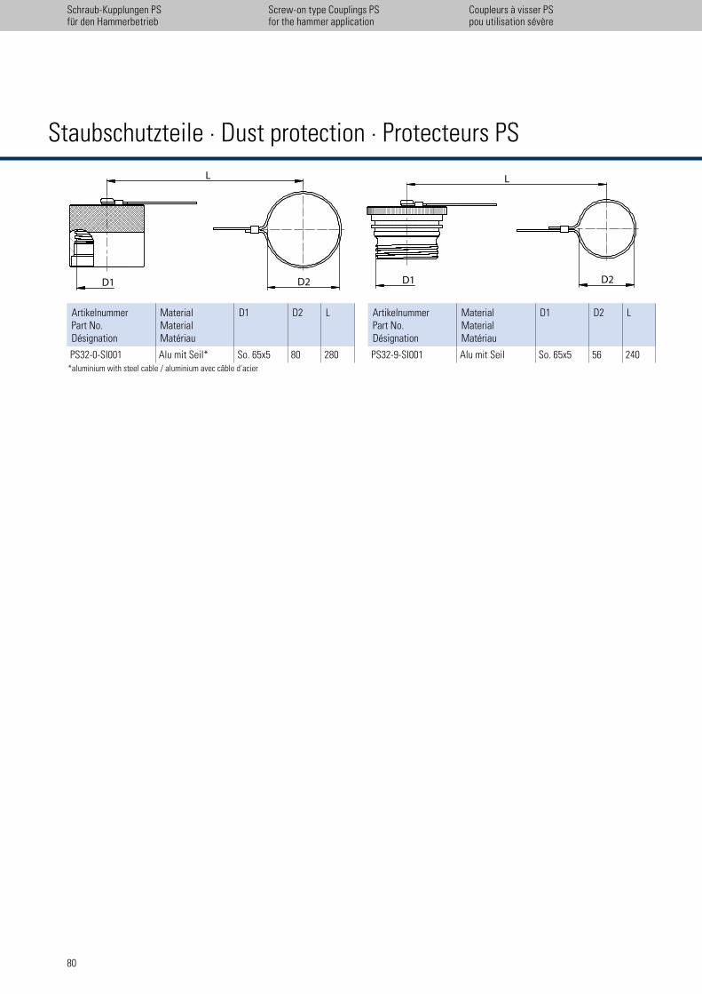
L�
D2D1
�L
D2D1
ArtikelnummerPart No.Désignation
MaterialMaterialMatériau
D1 D2 L
PS32-0-SI001 Alu mit Seil* So. 65x5 80 280
ArtikelnummerPart No.Désignation
MaterialMaterialMatériau
D1 D2 L
PS32-9-SI001 Alu mit Seil So. 65x5 56 240*aluminium with steel cable / aluminium avec câble d‘acier
Staubschutzteile · Dust protection · Protecteurs PS
80
Schraub-Kupplungen PS für den Hammerbetrieb
Coupleurs à visser PS pou utilisation sévère
Screw-on type Couplings PSfor the hammer application
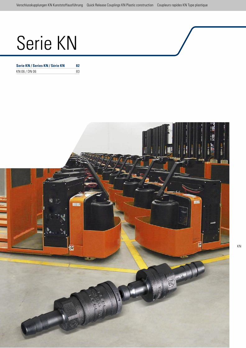
Serie KN / Series KN / Série KN 82
KN 06 / DN 06 83
Verschlusskupplungen KN Kunststoffausführung Quick Release Couplings KN Plastic construction Coupleurs rapides KN Type plastique
Serie KN
KN
Verschlusskupplungen KN Kunststoffausführung Quick Release Couplings KN Plastic construction Coupleurs rapides KN Type plastique
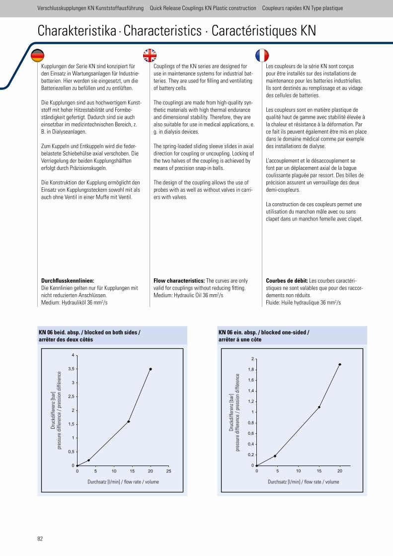
82
Durchflusskennlinien: Die Kennlinien gelten nur für Kupplungen mit nicht reduzierten Anschlüssen. Medium: Hydrauliköl 36 mm2/s
Flow characteristics: The curves are only valid for couplings without reducing itting. Medium: Hydraulic Oil 36 mm2/s
Courbes de débit: Les courbes caractéri-stiques ne sont valables que pour des raccor-dements non réduits. Fluide: Huile hydraulique 36 mm2/s
KN 06 beid. absp. / blocked on both sides / arrêter des deux côtés
Dru
ckdi
ffer
enz
[bar
]pr
essu
re d
iffer
ence
/ p
ress
ion
diff
éren
ce
Durchsatz [l/min] / low rate / volume
KN 06 ein. absp. / blocked one-sided / arrêter á une côte
Durchsatz [l/min] / low rate / volume
Dru
ckdi
ffer
enz
[bar
]pr
essu
re d
iffer
ence
/ p
ress
ion
diff
éren
ce
Kupplungen der Serie KN sind konzipiert für den Einsatz in Wartungsanlagen für Industrie-batterien. Hier werden sie eingesetzt, um die Batteriezellen zu befüllen und zu entlüften.
Die Kupplungen sind aus hochwertigem Kunst-stoff mit hoher Hitzestabilität und Formbe-ständigkeit gefertigt. Dadurch sind sie auch einsetzbar im medizintechnischen Bereich, z. B. in Dialyseanlagen.
Zum Kuppeln und Entkuppeln wird die feder-belastete Schiebehülse axial verschoben. Die Verriegelung der beiden Kupplungshälften erfolgt durch Präzisionskugeln.
Die Konstruktion der Kupplung ermöglicht den Einsatz von Kupplungssteckern sowohl mit als auch ohne Ventil in einer Muffe mit Ventil.
Couplings of the KN series are designed for use in maintenance systems for industrial bat-teries. They are used for illing and ventilating of battery cells.
The couplings are made from high-quality syn-thetic materials with high thermal endurance and dimensional stability. Therefore, they are also suitable for use in medical applications, e. g. in dialysis devices.
The spring-loaded sliding sleeve slides in axial direction for coupling or uncoupling. Locking of the two halves of the coupling is achieved by means of precision snap-in balls.
The design of the coupling allows the use of probes with as well as without valves in carri-ers with valves.
Les coupleurs de la série KN sont conçus pour être installés sur des installations de maintenance pour les batteries industrielles. Ils sont destinés au remplissage et au vidage des cellules de batteries.
Les coupleurs sont en matière plastique de qualité haut de gamme avec stabilité élevée à la chaleur et résistance à la déformation. Par ce fait ils peuvent également être mis en place dans le domaine médical comme par exemple des installations de dialyse.
L’accouplement et le désaccouplement se font par un déplacement axial de la bague coulissante plaguée par ressort. Des billes de précision assurent un verrouillage des deux demi-coupleurs.
La construction de ces coupleurs permet une utilisation du manchon mâle avec ou sans clapet dans un manchon femelle avec clapet.
Charakteristika · Characteristics · Caractéristiques KN
Verschlusskupplungen KN Kunststoffausführung Quick Release Couplings KN Plastic construction Coupleurs rapides KN Type plastique
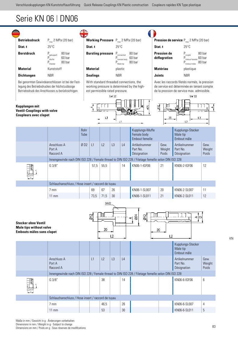
83
Verschlusskupplungen KN Kunststoffausführung Quick Release Couplings KN Plastic construction Coupleurs rapides KN Type plastique
RohrTube
Kupplungs-MuffeFemale bodyEmbout femelle
Kupplungs-SteckerMale tipEmbout mâle
Anschluss APort ARaccord A
Ø D2 L1 L2 L3 L4 ArtikelnummerPart No.Désignation
Gew.WeightPoids
ArtikelnummerPart No.Désignation
Gew.WeightPoids
Innengewinde nach DIN ISO 228 / Female thread to DIN ISO 228 / Filetage femelle selon DIN ISO 228
G 3/8“ 57,5 55,5 14 KN06-1-IGF06 21 KN06-2-IGF06 12
Schlauchanschluss / Hose insert / raccord de tuyau
7 mm 69 67 26 KN06-1-SL007 20 KN06-2-SL007 11
11 mm 73,5 71,5 30 KN06-1-SL011 21 KN06-2-SL011 12
Betriebsdruck Pmax
2 MPa (20 bar)
Stat. t 25°C
Berstdruck Pgekuppelt
80 bar P
Muffe 60 bar
PStecker
80 bar
Material Kunststoff
Dichtungen NBR
Bei genormten Gewindeanschlüssen ist bei der Fest-legung des Betriebsdruckes der höchstzulässige Betriebsdruck des Anschlusses zu berücksichtigen.
Working Pressure Pmax
2 MPa (20 bar)
Stat. t 25°C
Bursting pressure Pconnected
80 bar P
Female body 60 bar
PMale tip
80 bar
Material plastic
Sealings NBR
With standard threaded connections, the working pressure is determined by the high-est permissible rated pressure.
Pression de service Pmax
2 MPa (20 bar)
Stat. t 25°C
Pression de Pcouplé
80 bardéflagration P
Embout femelle 60 bar
PEmbout mâle
80 bar
Matériau plastique
Joints NBR
Avec les raccords iletés normés, la pression de service est déterminée en tenant compte de la pression de service max. admissible.
Kupplungs-SteckerMale tipEmbout mâle
Anschluss APort ARaccord A
L1 L2 L3 L4 ArtikelnummerPart No.Désignation
Gew.WeightPoids
Innengewinde nach DIN ISO 228 / Female thread to DIN ISO 228 / Filetage femelle selon DIN ISO 228
G 3/8“ 38 14 KN06-6-IGF06 6
Schlauchanschluss / Hose insert / raccord de tuyau
7 mm 46,5 26 KN06-6-SL007 4
11 mm 53 30 KN06-6-SL011 5
Kupplungen mitVentil-Couplings with valveCoupleurs avec clapet
Stecker ohne VentilMale tips without valveEmbouts mâles sans clapet
Maße in mm / Gewicht in g · Änderungen vorbehaltenDimensions in mm / Weight in g · Subject to change Dimensions en mm / Poids en g · Sous réserves de modiications
Serie KN 06 | DN06
KN
L4
L4

Sonderapplikationen
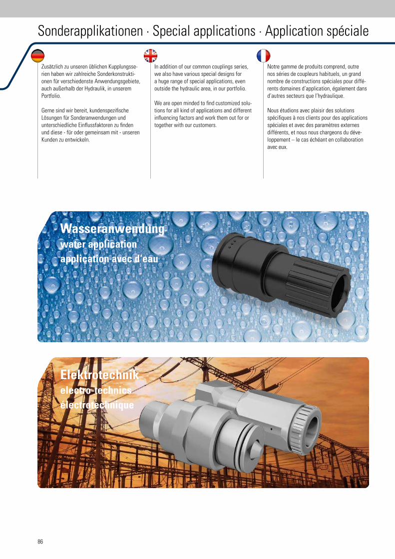
86
Zusätzlich zu unseren üblichen Kupplungsse-rien haben wir zahlreiche Sonderkonstrukti-onen für verschiedenste Anwendungsgebiete, auch außerhalb der Hydraulik, in unserem Portfolio.
Gerne sind wir bereit, kundenspeziische Lösungen für Sonderanwendungen und unterschiedliche Einlussfaktoren zu inden und diese - für oder gemeinsam mit - unseren Kunden zu entwickeln.
In addition of our common couplings series, we also have various special designs for a huge range of special applications, even outside the hydraulic area, in our portfolio.
We are open minded to ind customized solu-tions for all kind of applications and different inluencing factors and work them out for or together with our customers.
Notre gamme de produits comprend, outre nos séries de coupleurs habituels, un grand nombre de constructions spéciales pour diffé-rents domaines d’application, également dans d’autres secteurs que l’hydraulique.
Nous étudions avec plaisir des solutions spéciiques à nos clients pour des applications spéciales et avec des paramètres externes différents, et nous nous chargeons du déve-loppement – le cas échéant en collaboration avec eux.
Wasseranwendungwater application
application avec d‘eau
Elektrotechnikelectro-technics
électrotechnique
Sonderapplikationen · Special applications · Application spéciale
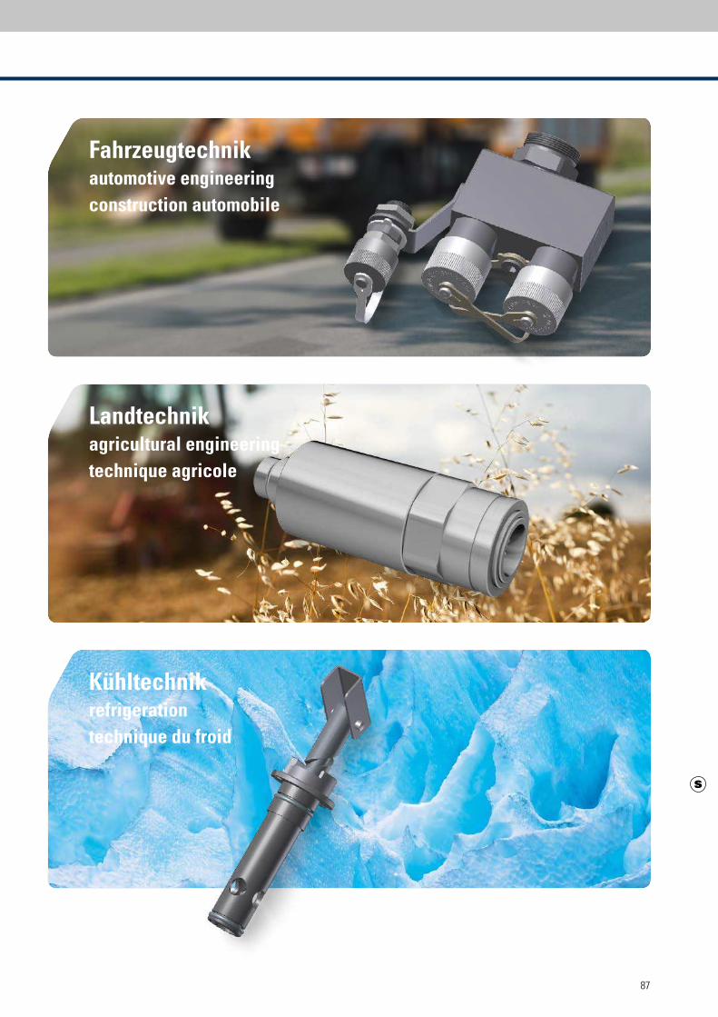
87
Landtechnikagricultural engineering
technique agricole
Fahrzeugtechnikautomotive engineering
construction automobile
Kühltechnikrefrigeration
technique du froid

Zubehör
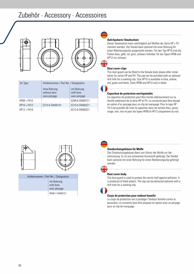
90
Aufclipsbarer StaubschutzDieser Staubschutz kann nachträglich auf Muffen der Serie HP + FH montiert werden. Der Deckel kann optional mit einer Bohrung für einen Markierungsclip ausgerüstet werden. Für den Typ HP10 sind die Farben blau, gelb, rot, grün, schwarz lieferbar, für die Typen HP08 und HP12 nur schwarz.
Dust cover clipsThis dust guard can be itted to the female body sleeve after instal-lation for series HP and FH. The cap can be provided with an optional drill hole for a marking clip. Size HP10 is available in blue, yellow, red, green and black. Sizes HP08 and HP12 only in black.
Capuchon de protection encliquetableCe capuchon de protection peut être monté ultérieurement sur la douille extérieure de la série HP et FH. Le couvercle peut être équipé en option d’un perçage pour un clip de marquage. Pour le type HP 10 il est possible de livrer le capuchon dans les teintes bleu, jaune, rouge, vert, noir et pour les types HP08 et HP12 uniquement du noir.
für Type Artikelnummer / Part No. / Designation
ohne Bohrungwithout boresans perçage
mit Bohrungwith boreavec perçage
HP08 + FH10 SZ08-6-SW001C1
HP10 + FH12 SZ10-6-SW001A1 SZ10-6-SW002C1
HP12 + FH19 SZ12-6-SW002C1
Zubehör · Accessory · Accessoires
Staubschutzgehäuse für MuffeDas Staubschutzgehäuse dient zum Schutz der Muffe vor Ver-schmutzung. Es ist aus schwarzem Kunststoff gefertigt. Der Deckel kann optional mit einer Bohrung für einen Markierungsclip gefertigt werden.
Dust cover bodyThe dust guard is used to protect the carrier half against pollution. It is produced of black plastic. The cap can be delivered optional with a drill hole for a marking clip.
Corps de protection pour embout femelleLe corps de protection sert à protéger l’embout femelle contre la poussière. Le couvercle peut être proposé en option avec un perçage pour un clip de marquage.
Artikelnummer / Part No. / Designation
mit Bohrungwith boreavec perçage
RH08-7-SW001C1
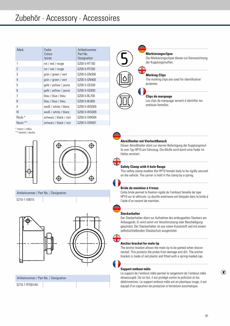
91
MarkierungsclipseDie Markierungsclipse dienen zur Kennzeichnung der Kupplungsmuffen.
Marking ClipsThe marking clips are used for identiication purposes.
Clips de marquageLes clips de marquage servent à identiier les embouts femelles.
Abreißhalter mit VierlochflanschDieser Abreißhalter dient zur starren Befestigung der Kupplungsmuf-fe vom Typ HP10 am Fahrzeug. Die Muffe wird durch eine Feder im Halter arretiert.
Safety Clamp with 4-hole flangeThis safety clamp enables the HP10 female body to be rigidly secured on the vehicle. The carrier is held in the clamp by a spring.
Bride de maintien à 4 trousCette bride permet la ixation rigide de l’embout femelle de type HP10 sur le véhicule. La douille extérieure est bloquée dans la bride à l’aide d’un ressort de maintien.
SteckerhalterDer Steckerhalter dient zur Aufnahme des entkuppelten Steckers am Anbaugerät. Er wird somit vor Verschmutzung oder Beschädigung geschützt. Der Steckerhalter ist aus rotem Kunststoff und mit einem selbstschließenden Staubschutz ausgerüstet.
Anchor bracket for male tipThe anchor bracket allows the male tip to be parked when discon-nected. This protects the probe from damage and dirt. The anchor bracket is made of red plastic and itted with a spring-loaded cap.
Support embout mâleLe support de l’embout mâle permet le rangement de l’embout mâle désaccouplé. De ce fait, il est protégé contre la pollution et les détériorations. Le support embout mâle est en plastique rouge, il est équipé d’un capuchon de protection à fermeture automatique.
Mark. FarbeColourteinte
ArtikelnummerPart No.Designation
1 rot / red / rouge SZ00-5-RT100
2 rot / red / rouge SZ00-5-RT200
3 grün / green / vert SZ00-5-GN300
4 grün / green / vert SZ00-5-GN400
5 gelb / yellow / jaune SZ00-5-GE500
6 gelb / yellow / jaune SZ00-5-GE600
7 blau / blue / bleu SZ00-5-BL700
8 blau / blue / bleu SZ00-5-BL800
II weiß / white / blanc SZ00-5-WS005
III weiß / white / blanc SZ00-5-WS009
Rückl.* schwarz / black / noir SZ00-5-SW004
Neutr.** schwarz / black / noir SZ00-5-SW001
Artikelnummer / Part No. / Designation
SZ10-1-V0015
Artikelnummer / Part No. / Designation
SZ10-1-RT001A0
Zubehör · Accessory · Accessoires
* return / relux** neutral / neutre
92
Dichtsätze · Seal Kit · Joint remplacement
Dichtsätze / seal kit / joint remplacement Inhalt pro Beutel / capacity per bag / capacité par sac
Typ / Type / Type Artikelnummer / Part No. / Désignation Bezeichnung / Description Désignation Menge / Amount / Quantité
für Muffe / for female body / pour embout femelle
HP04 HP04-1DICHTSATZ O-Ring1 25
Stützring2 25
HP08 HP08-1DICHTSATZ O-Ring 25
Stützring 25
HP08A HP08A1DICHTSATZ O-Ring 20
Stützring 20
HP10 HP10-1DICHTSATZ O-Ring 50
HP12 HP12-1DICHTSATZ O-Ring 25
Stützring 25
HP20 HP20-1DICHTSATZ O-Ring 25
Stützring 25
für Stecker / for male tip / pour embout mâle
FH06 FH06-2DICHTSATZ O-Ring 25
PTFE-Ring3 25
FH10 FH10-2DICHTSATZ O-Ring 25
Proildichtung4 25
FH12 FH12-2DICHTSATZ O-Ring 25
Proildichtung 25
FH16 FH16-2DICHTSATZ O-Ring 25
PTFE-Ring 25
FH19 FH19-2DICHTSATZ O-Ring 25
Proildichtung 25
FH25 FH25-2DICHTSATZ O-Ring 10
PTFE-Ring 10
für Muffe / for female body / pour embout femelle
HS04 HS04-1DICHTSATZ O-Ring 25
Stützring 25
Bremsring5 25
HS08 HS08-1DICHTSATZ O-Ring 25
Stützring 25
Bremsring 25
HS10 HS10-1DICHTSATZ O-Ring 50
Stützring 50
Bremsring 50
HS12 HS12-1DICHTSATZ O-Ring 25
Stützring 25
Bremsring 25
HS20 HS20-1DICHTSATZ O-Ring 25
Stützring 25
Bremsring 25
HS25 HS25-1DICHTSATZ O-Ring 10
Stützring 10
Bremsring 10
93
Dichtsätze · Seal Kit · Joint remplacement
Dichtsätze / seal kit / joint remplacement Inhalt pro Beutel / capacity per bag / capacité par sac
Typ / Type / Type Artikelnummer / Part No. / Désignation Bezeichnung / Description Désignation Menge / Amount / Quantité
für Stecker / for male tip / pour embout mâle
FT10 FT10-2DICHTSATZ O-Ring 10
Proildichtring 10
O-Ring 10
FT12 FT12-2DICHTSATZ O-Ring 10
Proildichtring 10
O-Ring 10
FT16 FT16-2DICHTSATZ O-Ring 10
Proildichtring 10
O-Ring 10
FT19 FT19-2DICHTSATZ O-Ring 10
Proildichtring 10
O-Ring 10
FT32 FT32-2DICHTSATZ O-Ring 10
Proildichtring 10
O-Ring 10
für Muffe / for female body / pour embout femelle
PS32 PS32-1DICHTSATZ Stützring 5
O-Ring 5
O-Ring 5
für Muffe / for female body / pour embout femelle
RH08 RH08-1DICHTSATZ O-Ring 25
Stützring 25
RH12 RH12-1DICHTSATZ O-Ring 25
Stützring 25
RH16 RH16-1DICHTSATZ O-Ring 10
Stützring 10
RK20 RK20-1DICHTSATZ O-Ring 10
Stützring 10
RH25 RH25-1DICHTSATZ O-Ring 10
Stützring 10
1 O-ring / Joint torique 2 Back up ring / Bague d‘appui 3 PTFE ring / PTFE joint torique
4 Proile packing / Proilé joint 5 Arrest ring / Bague d‘arrêt
Hinweis: Jegliche Demontage der Kupplung führt zum Erlöschen des Garantieanspruches
Advice: Any disconnection of the coupling leads up to the exipiration of the guarantee
Note: Tout démontage du coupleurs entraîne la perte des droits de garantie!
94
BG DN DN
BenennungDescriptionDésignation
CharakteristikaCharacteristicsCaractéristiques
SerieSeriesSérie
ZollInchPouce
metrischISO 4397
Steck-Kupplung
Quick release coupling
Coupleur enichable
Push-Pull-AusführungAbreißfunktionPush-pull-typeBreakaway functionType push-pull / Fonction de rupture
HP04HP08HP10HP12HP20
12346
1/4“3/8“1/2“3/4“1“
6,3 1012,5 19 (20) 25
Flachdichtende Kupplungen
Flat face coupling
Type à face plan
entspricht ISO 16028
acc. to ISO 16028
selon à ISO 16028
Stecker unter Druck kuppelbarMale part connect under pressureembout mâle peu être couplé sous pression
FH06FH10FH12FH16FH19FH25FX32
FU10FU12FU19
123468
10
236
1/4“3/8“1/2“5/8“3/4“1“1 1/4“
3/8“1/2“3/4“
6,3 10 12,5 16 19 25 31,5
10 12,5 19
Flachdichtende KupplungenFlat face couplingType à face plan
Edelstahl, entspricht ISO 16028Stainless steel, accc. to ISO 16028acier afine, selon ISO 16028
FH10 VAFH12 VAFH19 VA
236
3/8“1/2“3/4“
10 12,5 19
Bremsleitungs-KupplungCoupling for tractor braking systemCoupleur pour freinage hydraulique
Leckarme Flachdichtung entspr. ISO 5676Small leakage acc. to ISO 5676Faible fuite selon à ISO 5676
BP10 3 1/2“ 12,5
Schraubkupplung
Screw-on type coupling
Coupleur à visser
Kuppelbar unter Druckohne / mit WerkzeugConnect under pressurewithout / with toolPouvant être couplé sous pressionsans / avec outil
HS04HS08HS10HS12HS20HS25
123468
1/4“3/8“1/2“3/4“1“1 1/2“
6,3 10 12,5 19 25 38
SchraubkupplungScrew-on type couplingCoupleur à visser
Flachdichtende Schraub-KupplungFlat face screw coupling Coupleurs à visser à garniture plate
FT10FT12 FT16FT19FT25FT32
23 468
10
3/8“1/2“ 5/8“3/4“1“ 1 1/4“
10 12,5 16 19 25 31,5
Rohrleitungs-KupplungPipeline couplingCoupleur por tuyauterie
Flachdichtende Schraub-KupplungFlat face screw coupling Coupleurs à visser à garniture plate
RH08RH12RH16RK20RH25
23468
3/8“1/2“5/8“3/4“1“
10 12,5 16 19 25
SchraubkupplungScrew-on type couplingCoupleur à visser
für den Hammerbetrieb, for hammer application, pour utilisation sévère
PS 32 8 1 1/4“ 31,5
Kunststoff-KupplungPlastic couplingCoupleur plastique
Auch ohne VentileAlso without valvesEgalement sans clapet
KN06 1 1/4“
Übersicht Kupplungen · Couplings Selector Guide · Table de sélection
* Kurzzeitig möglich / Short term possible 1 Serie / Series / Série FH Operating pressure Court terme possible
95
Amin
Qmax
Betriebs-druckWorking-pressurePressionde service1
Berstdruck / bursting pressure / Pression de délagration
LeckölLeakageFuite
gekuppeltconnectedcouplé
MuffeFemalebodyEmboutfemelle
SteckerMaletipEmboutmâle
metrischISO 4397
mm2 l/min bar bar bar bar ml
244576
130256
204080
120160
250250250250250
10001000100010001000
10001000100010001000
100010001000700700
0,81,21,78,0
12,0
2963
147127156251350
63147156
4080
120140180260600
80120180
400350350350350260300
350350350
17001500120012001450
8001000
170015001600
12201050100011001050
8001000
15001100105011001050800
1000
150014001600
0,010,015
0,020,02
0,0320,03
0,0150,02
0,032
63147156
80120180
250250250
130013001300
750750750
100010001000
0,015 0,02
0,032
70 150 315 75 150
244576
130256660
204080
120160220
450450400400300300
180016001400150011801800
140017501200160015001600
140015501200120011001200
63147 139156 251 506
80120 140180 260 600
550550 550500470400
14001400 1400140013001100
11001000 1000105010001100
14001400 1600140013001100
0,04 0,025
0,018 0,06
55105160285620
4070
105120500
420420420350420
16001260126010001150
16001260126010001100
1600126012601200
900
0,08
467 660 (1000)* 380 1520 1520 1520 27,0
26,4 20 20 80 60 80
96
Wichtig !Falsche Auswahl oder falsche und unsachge-mäße Handhabung von Verschlusskupplungen und Zubehör kann zu Sach- und Personenschä-den führen.
• Austreten von Hydrauliklüssigkeiten unter hohem Druck
• Explosion oder Entlammen des verwende-ten Fluids
• Zusammenstoß mit sich in Bewegung setzenden oder absinkenden Bauteilen, verursacht durch den Ausfall des Hydraulik-kreislaufs
• Gefährliches Ausschlagen der Hydraulik-schlauchleitung (sogenannter Peitschenef-fekt)
• Verletzungsgefahr durch den Kontakt mit dem heißen, kalten oder aus anderen Gründen gefährlichen Fluid
Bevor Sie eine Schnellverschlusskupplung oder das entsprechende Zubehör auswählen und einsetzen, sollten Sie unbedingt die folgenden Anweisungen befolgen.
1 Allgemeine Hinweise
1.1 AllgemeinesDieser Abschnitt enthält Anweisungen zur Auswahl und Handhabung (Einbau, Ein-und Auskuppelvorgang und Wartung). Dies ist als zusätzlicher Sicherheitshinweis zu verstehen und muss beim Einsatz der Produkte berücksich-tigt werden.
1.2 SicherheitsvorkehrungenVerschlusskupplungen können unter Umständen unvorhergesehen ausfallen. Berücksichtigen Sie dies bei der Planung des Systems oder Anlage durch Sicherheitseinrichtungen.
1.3 Information für den AnwenderGeben Sie diese Sicherheitshinweise an die Personen weiter, die für die Auswahl oder Handhabung verantwortlich sind. Setzen Sie die Verschlusskupplungen nur ein, nachdem Sie die produktspeziischen Informationen erhalten bzw. verstanden haben.
Sicherheitshinweise
1.4 Verantwortlichkeit des AnwendersAufgrund der vielseitigen Anwendungsmöglich-keiten von Verschlusskupplungen kann nicht jeder Anwendungsfall und jedes technische Detail berücksichtigt werden.
Der Anwender ist verantwortlich für - die Endauswahl des Produkts- die Erfüllung der Anforderungen durch den
Betreiber - die Sicherheit der Personen und Anlage - die Sicherheitsvorkehrungen, die beim Ein-
satz der Verschlusskupplungen erforderlich sind
Bei weiteren Fragen wenden Sie sich bitte an unseren Vertrieb.
2 Hinweise für die richtige Kupplungsauswahl
2.1 DruckbereichDie Auswahl der Verschlusskupplung muss so getroffen werden, dass der maximal zulässige Betriebsdruck der Kupplung größer oder gleich dem Systemdruck ist. Druckspitzen im System, die oberhalb des Betriebsdrucks liegen, verrin-gern die Lebensdauer der Kupplung und müssen deshalb bei der Auswahl berücksichtigt werden.
2.2 MedienbeständigkeitDie Dichtungswerkstoffe in den Verschluss-kupplungen sind für eine Vielzahl von Druckme-dien geeignet.Informationen über die Verträglichkeit des Fluids erfragen Sie beim Produktmanager.
2.3 EinsatztemperaturDie Angaben zu den Einsatztemperaturen in den Speziikationen sind Maximalwerte. Diese Wer-te sind im stehenden und ließenden Kreislauf nicht zu überschreiten. Bei der Betätigung ist die natürliche Erwärmung der Verschlusskupp-lung zu beachten.
2.4 BaugrößeDie Auswahl der Baugröße und der An-schlussform ist abhängig von der geforderten Leistungsübertragung. Hierzu sind die entspre-chenden Diagramme zu verwenden.Durchlussmenge, Druckverlust und Strömungs-geschwindigkeit sind bei der Auswahl der richtigen Baugröße zu beachten .Werden diese Werte im Betrieb überschritten, kann es zu Funktionsstörungen innerhalb der Verschlusskupplung kommen.
2.5 Mechanische VerbindungDas Verbinden der Kupplungshälften erfolgt je nach Bauart.Hierbei ist auf das vollständige Einrasten bei Steckkupplungen bzw. auf die vollständige Verschraubung der Schraubhülse bis Anschlag zu achten.Das gewaltsame und nicht sachgemäße Tren-nen der Verschlusskupplung führt zu Funktions-störungen.
2.6 Thermische BelastungDurch starke Erwärmung über die empfohlene Einsatztemperatur hinaus, wie durch Schwei-ßen oder Löten an den Kupplungen, können gefährliche Gase entstehen. Außerdem wird der Oberlächenschutz (Verzinkung) beschädigt. Die Funktionsfähigkeit kann dadurch gestört werden.
2.7 RichtlinienDie für den Einsatzbereich geltenden Spe-ziikationen, Standards und Normen sowie technische Regeln sind bei der Auswahl einzuhalten.
Sicherheitshinweise für die Handhabung von Schnellverschlusskupplungen
und dem entsprechenden Zubehör
97
Important !Incorrect selection or incorrect and inexpert handling of couplings and accessories may result in property damage or personal injury.
• High velocity luid discharge• Explosion or combustion of the conveyed
luid• Collision with moving or dropping com-
ponents, caused by failure of a hydraulic circuit
• Dangerous whipping of hydraulic hoses• Risk of injury through contacting hot, cold
or otherwise dangerous luids
Read and observe the following instructions prior to selecting and using a snap-in coupling or associated accessories.
1 General Notes
1.1 GeneralThis section contains instructions on selec-tion and handling (installation, coupling and uncoupling and maintenance). This is to be understood as additional safety notes and must be taken into consideration in the use and ap-plication of the products.
1.2 Safety MeasuresCouplings may possibly fail without prior warn-ing. Take this into consideration when planning the safety devices of your system or plant.
1.3 Information for the UserForward these safety notes to the persons responsible for the selection and handling of couplings. Use only couplings for which you have received and understood product-speciic information.
Safety Regulations
1.4 Responsibility of the UserDue to the versatile range of applications of couplings, not every application case and every technical detail can be dealt with in this document.
The user is responsible for: - inal selection of the product- fulilment or requirements by the operator - safety of operating personnel and plant - safety measures necessary in the use of
couplings
Should you have any further questions, please contact our sales department.
2 Correct Selection of Couplings
2.1 Pressure RangeThe coupling to be used must be selected so that the maximum permissible operating pres-sure is equal to or higher than the system pres-sure. Pressure peaks in the system in excess of the operating pressure reduce the service life of the couplings and therefore should be taken into consideration when making the selection.
2.2 Resistance to MediaThe sealing materials in the couplings are suitable for a large variety of pressure media. Information on the compatibility of a particular type of luid are available upon request from product manager.
2.3 Operating TemperatureThe indication of operating temperatures in the technical speciications represents maximum values. These values may not be exceeded in standing or lowing circuits. For actuation the natural warming of the coupling must also be taken into consideration.
2.4 SizeThe selection of the size and type of connection depends on the required transmission of forces. For this purpose, refer to the corresponding diagrams. Flow volume, pressure loss and low speed should be taken into consideration when selecting the correct size of a coupling. Should these values be exceeded, malfunctions within the coupling may occur.
2.5 Mechanical ConnectionThe connection of the two halves of a coupling is achieved depending on the type. It is impor-tant to observe the positive engagement of plug-type couplings and the secure tightening of screw-type couplings to the limit stop of the thread. Forced or improper separation will result in malfunction of the coupling.
2.6 Thermal StressExcessive warming of the coupling above the recommended operating temperature, for instance due to welding or soldering, can cause the formation of dangerous gases. In addition, the protective surface inish (galvanization) will be damaged and the function of the coupling may be impaired.
2.7 GuidelinesApplicable speciications, standards and regula-tions as well as technical rules must be taken into consideration in the selection of couplings.�
Safety Regulations for Handling of Quick Release Couplings
and Accessories
98
Attention !Un mauvais choix et une manipulation par un personnel non qualiié des coupleurs rapides et leurs accessoires peuvent conduire à des dommages matériels et personnels.
• émergence de luides hydrauliques sous haute pression
• explosion ou inlammation du luide utilisé• chocs avec des éléments en mouvement
provoquant une panne du circuit hydrauli-que
• décrochage dangereux de la conduite hydraulique (effet coup de fouet)
• danger dû au contact avec un luide chaud, froid ou dangereux.
Avant de choisir et installer un coupleur rapide ou l‘accessoire correspondant, vous devez impérativement vous reporter aux indications suivantes.
1 Indications générales
1.1 GénéralitésCe paragraphe renferme des indications pour le choix et la manipulation (montage, procé-dure de couplage et découplage ainsi que la maintenance). Ce sont des conseils qui doivent impérativement être pris en compte lors de l‘utilisation de ces produits.
1.2 Précautions de sécuritéIl peut arriver qu’il y ait un dysfonctionnement des coupleurs pour une raison indéterminée. Veuillez en tenir compte lors de la conception du système ou de la centrale en prévoyant un mécanisme de sûreté.
1.3 Informations destinées à l‘utilisateurTransmettez ces informations aux personnes responsables du choix ou de la manipulation. Ne montez que les coupleurs pour lesquels vous avez reçu et assimilés les informations spéciiques.
Consignes de sécurité
1.4 Responsabilité de l‘utilisateurEtant donné les multiples possibilités d‘utili-sation du coupleur on ne peut tenir compte de chaque cas d‘utilisation et de chaque détail technique.
L‘utilisateur est responsable- du choix inal du produit- du respect des consignes par l‘opérateur- de la sécurité des personnes et de la
centrale- des précautions de sécurité nécessaires
lors de l‘utilisation des coupleurs
Pour de plus amples informations, veuillez vous adresser à notre service commercial.
2 Indications pour le choix du bon coupleur
2.1 Plage de pressionLe choix du coupleur doit être faite de telle manière que la pression de fonctionnement admissible max. du coupleur, soit supérieure ou égale à la pression du système. Des pointes de pression du système, supérieures à la pression de fonctionnement, réduisent la durée de vie du coupleur et doivent par conséquent être prises en compte lors des critères de sélection.
2.2 Compatibilité aux fluidesLes matériaux des joints des coupleurs convien-nent à un grand nombre de luides.Vous recevrez des informations relatives à la compatibilité au luide en vous adressant au responsable produit.
2.3 Température d‘utilisationLes données concernant les températures d‘utilisation qui se trouvent dans les spéciica-tions sont des valeurs maximales. Ces valeurs ne doivent être dépassées, ni en statique ni en dynamique. Veuillez faire attention, lors de la mise en service, au réchauffement naturel du coupleur.
2.4 TailleLe choix de la taille et de la forme de raccord dépend des performances souhaitées. Utilisez à cet effet les diagrammes correspondants. Les débits, pertes de charge et vitesses du luide doivent être prises en compte lors de la sélection.Si ces vitesses sont dépassées, des dysfonc-tionnements peuvent survenir à l‘intérieur du coupleur.
2.5 Liaison mécaniqueLa liaison de chaque partie du coupleur se fait selon le type de construction.A cette effet, il faut impérativement visser ou encliqueter les coupleurs jusqu’en butée. Une séparation du coupleur effectuée avec force, ou par tout autre moyen peut provoquer des dysfonctionnements.
2.6 Charge thermiqueDes gaz dangereux peuvent être produits à cause d‘un fort réchauffement au delà de la température d‘utilisation recommandée, ou à cause de soudage au niveau des coupleurs.Outre cela, la protection de surface (zingage) peut être endommagée.Le fonctionnement peut alors être mis en cause.
2.7 DirectivesLes spéciications, standards et normes vala-bles pour le domaine d‘utilisation, ainsi que les règles techniques doivent être respectées lors du choix du coupleur.
Consignes de sécurité concernant la manipulation des coupleurs rapides
et accessoires correspondants
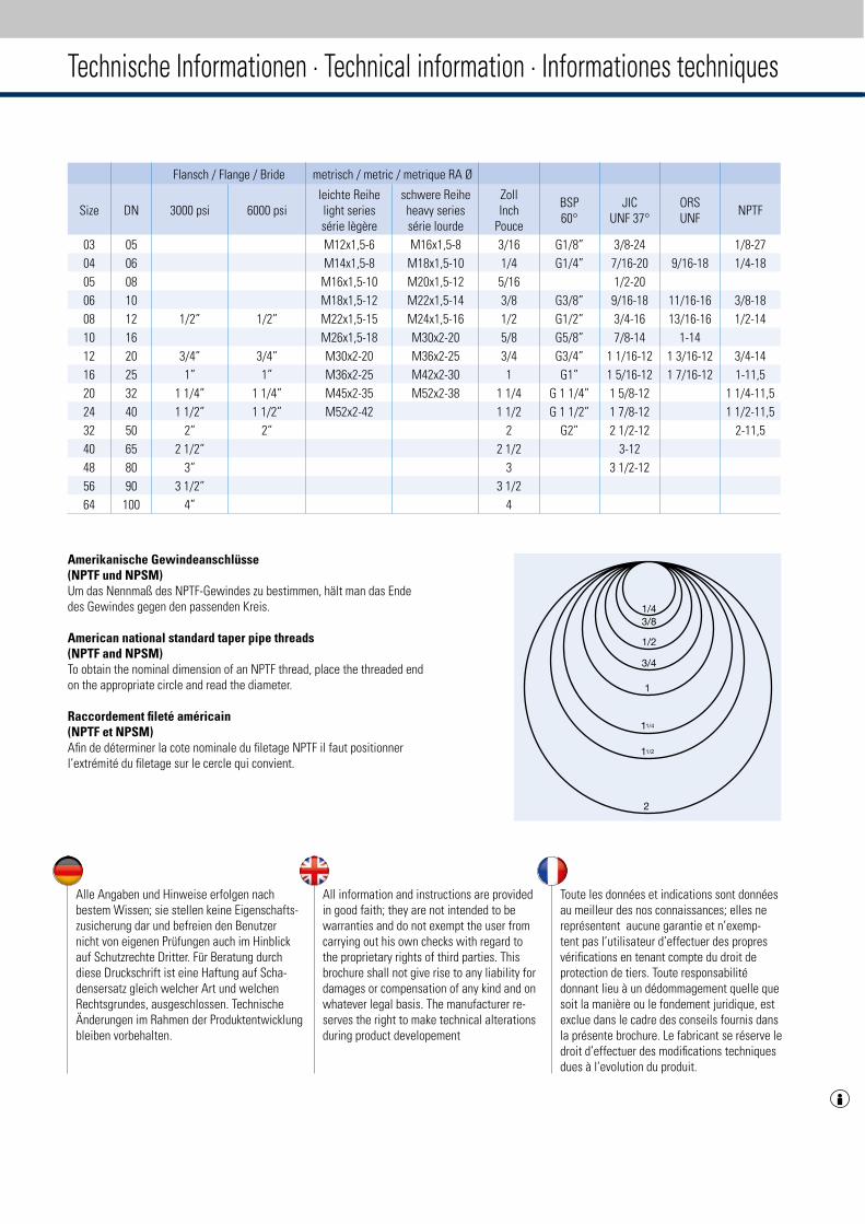
Technische Informationen · Technical information · Informationes techniques
Alle Angaben und Hinweise erfolgen nach bestem Wissen; sie stellen keine Eigenschafts-zusicherung dar und befreien den Benutzer nicht von eigenen Prüfungen auch im Hinblick auf Schutzrechte Dritter. Für Beratung durch diese Druckschrift ist eine Haftung auf Scha-densersatz gleich welcher Art und welchen Rechtsgrundes, ausgeschlossen. Technische Änderungen im Rahmen der Produktentwicklung bleiben vorbehalten.
All information and instructions are provided in good faith; they are not intended to be warranties and do not exempt the user from carrying out his own checks with regard to the proprietary rights of third parties. This brochure shall not give rise to any liability for damages or compensation of any kind and on whatever legal basis. The manufacturer re-serves the right to make technical alterations during product developement
Toute les données et indications sont données au meilleur des nos connaissances; elles ne représentent aucune garantie et n’exemp-tent pas l’utilisateur d’effectuer des propres vérifications en tenant compte du droit de protection de tiers. Toute responsabilité donnant lieu à un dédommagement quelle que soit la manière ou le fondement juridique, est exclue dans le cadre des conseils fournis dans la présente brochure. Le fabricant se réserve le droit d’effectuer des modifications techniques dues à l’evolution du produit.
Amerikanische Gewindeanschlüsse (NPTF und NPSM)Um das Nennmaß des NPTF-Gewindes zu bestimmen, hält man das Ende des Gewindes gegen den passenden Kreis.
American national standard taper pipe threads (NPTF and NPSM)To obtain the nominal dimension of an NPTF thread, place the threaded end on the appropriate circle and read the diameter.
Raccordement fileté américain(NPTF et NPSM)Afin de déterminer la cote nominale du filetage NPTF il faut positionner l’extrémité du filetage sur le cercle qui convient.
Flansch / Flange / Bride metrisch / metric / metrique RA Ø
Size DN 3000 psi 6000 psileichte Reihelight seriessérie lègère
schwere Reiheheavy seriessérie lourde
ZollInch
Pouce
BSP60°
JICUNF 37°
ORSUNF
NPTF
03 05 M12x1,5-6 M16x1,5-8 3/16 G1/8” 3/8-24 1/8-27
04 06 M14x1,5-8 M18x1,5-10 1/4 G1/4” 7/16-20 9/16-18 1/4-18
05 08 M16x1,5-10 M20x1,5-12 5/16 1/2-20
06 10 M18x1,5-12 M22x1,5-14 3/8 G3/8” 9/16-18 11/16-16 3/8-18
08 12 1/2” 1/2” M22x1,5-15 M24x1,5-16 1/2 G1/2” 3/4-16 13/16-16 1/2-14
10 16 M26x1,5-18 M30x2-20 5/8 G5/8” 7/8-14 1-14
12 20 3/4” 3/4” M30x2-20 M36x2-25 3/4 G3/4” 1 1/16-12 1 3/16-12 3/4-14
16 25 1” 1” M36x2-25 M42x2-30 1 G1” 1 5/16-12 1 7/16-12 1-11,5
20 32 1 1/4” 1 1/4” M45x2-35 M52x2-38 1 1/4 G 1 1/4” 1 5/8-12 1 1/4-11,5
24 40 1 1/2” 1 1/2” M52x2-42 1 1/2 G 1 1/2” 1 7/8-12 1 1/2-11,5
32 50 2” 2” 2 G2” 2 1/2-12 2-11,5
40 65 2 1/2” 2 1/2 3-12
48 80 3” 3 3 1/2-12
56 90 3 1/2” 3 1/2
64 100 4” 4

Voswinkel GmbHNeugrünenthal · D-58540 Meinerzhagen · Germany Phone: +49 (0) 23 54 / 705-0 · Fax: +49 (0) 23 54 / 705-150www.voswinkel.net KA
TALO
G-K
-14/
1506
/201
6