Embed Size (px)
Citation preview
LRTB GVTG
MULTILEDData SheetVersion 1.2
2018-03-29 1
Das Bauteil ist speziell für den Einsatz in Vollfarb-Videoleinwänden entwickelt worden. Die 6-lead Technologie läßt eine unahängige Ansteuerung aller Chips zu und bietet dadurch eine additive Farbmischung.
Merkmale• Gehäusetyp: weißes PLCC-6 Gehäuse, diffuser
Silikon Verguss, Kontrasterhöhung durch schwarze Oberfläche
• Farbe: Rot/True Grün/Blau, 625 nm (rot), 528 nm (true grün), 470 nm (blau)
• Abstrahlwinkel: Lambertscher Strahler (120°)• Lötmethode: Reflow lötbar• Vorbehandlung: nach JEDEC Level 4• ESD-Festigkeit: ESD -sensitives Bauteil
Hauptanwendungen• Videoleinwände• Vollfarb-Displays
This device is especially designed for full color video walls. The 6-lead technology admits an additive mixture of color stimuli by independent driving of each chip.
Features• package: white PLCC-6 package, diffused
silicone resin, higher contrast by a black surface
• color: red/true green/ blue, 625 nm (red), 528 nm (true green), 470 nm (blue)
• viewing angle: Lambertian Emitter (120°)• soldering methods: reflow solderable• preconditioning: acc. to JEDEC Level 4• ESD-withstand voltage: ESD sensitive device
Main Applications• video walls• full color displays
2018-03-29 2
LRTB GVTG
Anm: Die oben genannten Typbezeichnungen umfassen die bestellbaren Selektionen. Diese bestehen aus wenigenHelligkeitsgruppen (siehe Seite 7 für nähere Informationen). Es wird nur eine einzige Helligkeitsgruppe pro Gurtgeliefert. Z.B.: LRTB GVTG-U5V5-1+A5B5-29+S9T9-49 bedeutet, dass auf dem Gurt nur eine der HelligkeitsgruppenU5, U7, U9, V oder V5 enthalten ist.Um die Liefersicherheit zu gewährleisten, können einzelne Helligkeitsgruppen nicht bestellt werden.
Gleiches gilt für die Farben, bei denen Wellenlängengruppen gemessen und gruppiert werden. Pro Gurt wird nur eineWellenlängengruppe geliefert. Z.B.: LRTB GVTG-U5V5-1+A5B5-29+S9T9-49 bedeutet, dass auf dem Gurt nur eine derWellenlängengruppen -2, -3, -4, -5, -6, -7, -8 oder -9 enthalten ist (siehe Seite 8 für nähere Information). Z.B.:LRTB GVTG-U5V5-1+A5B5-29+S9T9-49 bedeutet, dass das Bauteil innerhalb der auf Seite 4 spezifizierten Grenzengeliefert wird.Um die Liefersicherheit zu gewährleisten, können einzelne Wellenlängengruppen nicht bestellt werden.
Anm: The above Type Numbers represent the order groups which include only a few brightness groups (see page 7 forexplanation). Only one group will be shipped on each reel (there will be no mixing of two groups on each reel). E.g.LRTB GVTG-U5V5-1+A5B5-29+S9T9-49 means that only one group U5, U7, U9, V or V5 will be shippable for any onereel.In order to ensure availability, single brightness groups will not be orderable.
In a similar manner for colors where wavelength groups are measured and binned, single wavelength groups will beshipped on any one reel. E.g. LRTB GVTG-U5V5-1+A5B5-29+S9T9-49 means that only 1 wavelength group -2, -3, -4,-5, -6, -7, -8 or -9 will be shippable (see page 8 for explanation). E.g. LRTB GVTG-U5V5-1+A5B5-29+S9T9-49 meansthat the device will be shiped within the specified limits as stated on page 4.In order to ensure availability, single wavelength groups will not be orderable..
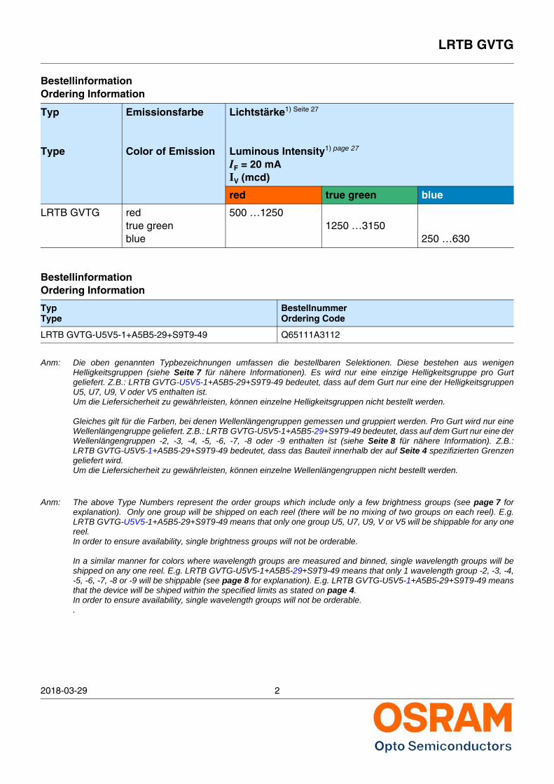
BestellinformationOrdering Information
Typ
Type
Emissionsfarbe
Color of Emission
Lichtstärke1) Seite 27
Luminous Intensity1) page 27
IF = 20 mAIV (mcd)
red true green blue
LRTB GVTG redtrue greenblue
500 …12501250 …3150
250 …630
BestellinformationOrdering Information
TypType
BestellnummerOrdering Code
LRTB GVTG-U5V5-1+A5B5-29+S9T9-49 Q65111A3112
LRTB GVTG
2018-03-29 3
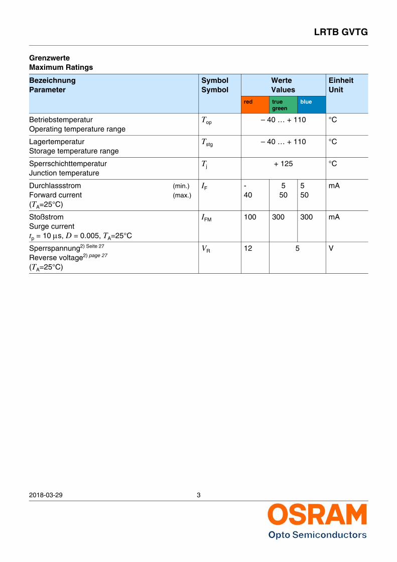
GrenzwerteMaximum Ratings
BezeichnungParameter
SymbolSymbol
WerteValues
EinheitUnit
red true green
blue
BetriebstemperaturOperating temperature range
Top – 40 … + 110 °C
LagertemperaturStorage temperature range
Tstg – 40 … + 110 °C
SperrschichttemperaturJunction temperature
Tj + 125 °C
Durchlassstrom (min.)Forward current (max.)(TA=25°C)
IF -40
550
550
mA
StoßstromSurge currenttp = 10 s, D = 0.005, TA=25°C
IFM 100 300 300 mA
Sperrspannung2) Seite 27
Reverse voltage2) page 27
(TA=25°C)
VR 12 5 V
2018-03-29 4
LRTB GVTG
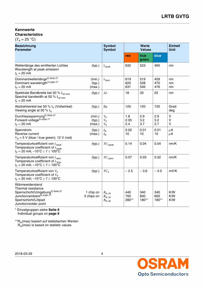
KennwerteCharacteristics(TA = 25 °C)
BezeichnungParameter
SymbolSymbol
WerteValues
EinheitUnit
red true green
blue
Wellenlänge des emittierten Lichtes (typ.)Wavelength at peak emissionIF = 20 mA
peak 632 523 465 nm
Dominantwellenlänge4) Seite 27 (min.)Dominant wavelength4) page 27 (typ.)IF = 20 mA (max.)
dom 619625631
519528546
459470476
nmnmnm
Spektrale Bandbreite bei 50 % Irel max (typ.)Spectral bandwidth at 50 % Irel maxIF = 20 mA
18 33 25 nm
Abstrahlwinkel bei 50 % IV (Vollwinkel) (typ.)Viewing angle at 50 % IV
2 120 120 120 Graddeg.
Durchlassspannung5) Seite 27 (min.)Forward voltage5) page 27 (typ.)IF = 20 mA (max.)
VFVFVF
1.82.052.4
2.93.23.7
2.93.23.7
VVV
Sperrstrom (typ.)Reverse current (max.)VR = 5 V (blue / true green); 12 V (red)
IRIR
0.0210
0.0110
0.0110
AA
Temperaturkoeffizient von peak (typ.)Temperature coefficient of peakIF = 20 mA; –10°C T 100°C
TCpeak 0.14 0.04 0.04 nm/K
Temperaturkoeffizient von dom (typ.)Temperature coefficient of domIF = 20 mA; –10°C T 100°C
TCdom 0.07 0.03 0.02 nm/K
Temperaturkoeffizient von VF (typ.)Temperature coefficient of VFIF = 20 mA; –10°C T 100°C
TCV – 2.5 – 3.6 – 4.0 mV/K
WärmewiderstandThermal resistanceSperrschicht/Umgebung3) Seite 27 1 chip onJunction/ambient3) page 27 3 chips onSperrschicht/LötpadJunction/solder point
Rth JARth JARth JS
440700280**
340600180**
340600180**
K/WK/WK/W
* Einzelgruppen siehe Seite 8Individual groups on page 8
**Rth(max) basiert auf statistischen WertenRth(max) is based on statistic values
LRTB GVTG
2018-03-29 5
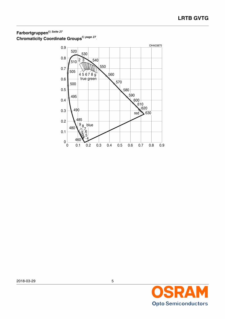
Farbortgruppen6) Seite 27
Chromaticity Coordinate Groups6) page 27 7
OHA03875
520530
540
550
560
570
580590
600610
620630
00
0.1
0.2
0.3
0.4
0.5
0.6
0.7
0.8
0.9
0.1 0.2 0.3 0.4 0.5 0.6 0.7 0.8 0.9
510
505
500
495
490
485
480
460
true green
9 blue
red
4 5 6
76
7
2 3
8 9
8
54
2018-03-29 6
LRTB GVTG
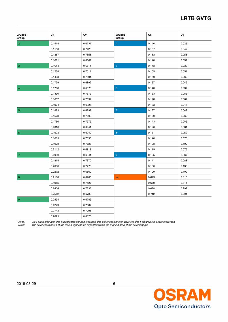
Gruppe Group
Cx Cy Gruppe Group
Cx Cy
2 0.1518 0.6731 4 0.146 0.029
0.1150 0.7420 0.157 0.047
0.1367 0.7558 0.153 0.056
0.1691 0.6862 0.140 0.037
3 0.1614 0.6811 5 0.143 0.033
0.1268 0.7511 0.155 0.051
0.1498 0.7591 0.150 0.062
0.1799 0.6892 0.137 0.042
4 0.1708 0.6879 6 0.140 0.037
0.1390 0.7573 0.153 0.056
0.1637 0.7599 0.148 0.069
0.1904 0.6928 0.133 0.048
5 0.1823 0.6892 7 0.137 0.042
0.1523 0.7599 0.150 0.062
0.1786 0.7573 0.143 0.083
0.2016 0.6941 0.126 0.061
6 0.1923 0.6940 8 0.131 0.052
0.1665 0.7598 0.146 0.073
0.1938 0.7527 0.138 0.100
0.2142 0.6912 0.119 0.078
7 0.2039 0.6941 9 0.125 0.067
0.1814 0.7570 0.141 0.088
0.2090 0.7476 0.130 0.130
0.2272 0.6869 0.109 0.109
8 0.2168 0.6906 red 0.693 0.310
0.1965 0.7527 0.679 0.311
0.2404 0.7336 0.698 0.292
0.2542 0.6738 0.712 0.291
9 0.2434 0.6789
0.2279 0.7387
0.2743 0.7096
0.2825 0.6573
Anm.: Die Farbkoordinaten des Mischlichtes können innerhalb des gekennzeichneten Bereichs des Farbdreiecks erwartet werden.Note: The color coordinates of the mixed light can be expected within the marked area of the color triangle
LRTB GVTG
2018-03-29 7
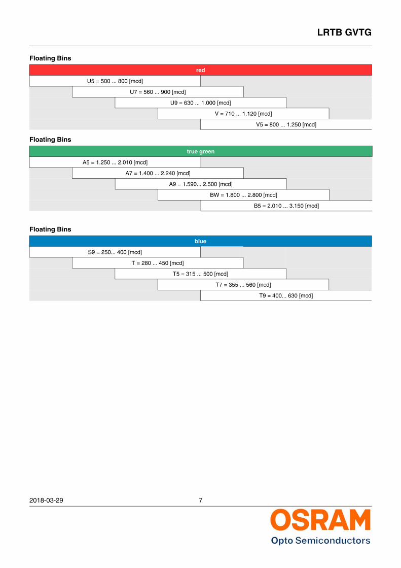
Floating Bins
red
U5 = 500 ... 800 [mcd]
U7 = 560 ... 900 [mcd]
U9 = 630 ... 1.000 [mcd]
V = 710 ... 1.120 [mcd]
V5 = 800 ... 1.250 [mcd]
Floating Bins
true green
A5 = 1.250 ... 2.010 [mcd]
A7 = 1.400 ... 2.240 [mcd]
A9 = 1.590... 2.500 [mcd]
BW = 1.800 ... 2.800 [mcd]
B5 = 2.010 ... 3.150 [mcd]
Floating Bins
blue
S9 = 250... 400 [mcd]
T = 280 ... 450 [mcd]
T5 = 315 ... 500 [mcd]
T7 = 355 ... 560 [mcd]
T9 = 400... 630 [mcd]
2018-03-29 8
LRTB GVTG
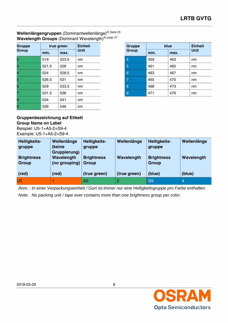
Wellenlängengruppen (Dominantwellenlänge)4) Seite 25
Wavelength Groups (Dominant Wavelength)4) page 27
GruppeGroup
true green EinheitUnit
GruppeGroup
blue EinheitUnit
min. max. min. max.
2 519 523.5 nm 4 459 463 nm
3 521.5 526 nm 5 461 465 nm
4 524 528.5 nm 6 463 467 nm
5 526.5 531 nm 7 465 470 nm
6 529 533.5 nm 8 468 473 nm
7 531.5 536 nm 9 471 476 nm
8 534 541 nm
9 539 546 nm
Gruppenbezeichnung auf EtikettGroup Name on LabelBeispiel: U5-1+A5-2+S9-4Example: U5-1+A5-2+S9-4
Helligkeits-gruppe
Brightness Group
(red)
Wellenlänge(keine Gruppierung)Wavelength(no grouping)
(red)
Helligkeits-gruppe
Brightness Group
(true green)
Wellenlänge
Wavelength
(true green)
Helligkeits-gruppe
Brightness Group
(blue)
Wellenlänge
Wavelength
(blue)
U5 1 A5 2 S9 4
Anm.: In einer Verpackungseinheit / Gurt ist immer nur eine Helligkeitsgruppe pro Farbe enthalten.
Note: No packing unit / tape ever contains more than one brightness group per color.
LRTB GVTG
2018-03-29 9
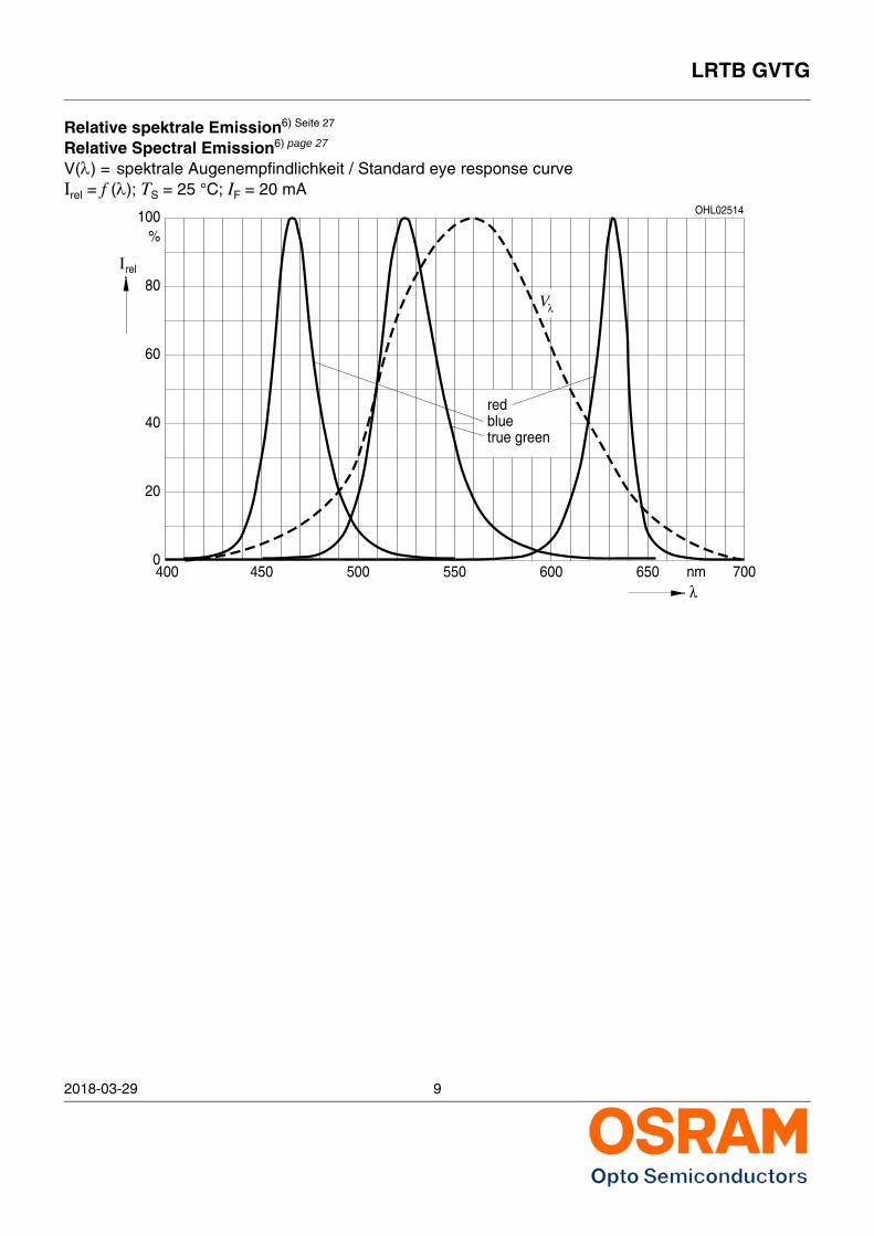
Relative spektrale Emission6) Seite 27
Relative Spectral Emission6) page 27
V() = spektrale Augenempfindlichkeit / Standard eye response curveIrel = f (); TS = 25 °C; IF = 20 mA
40
0400
20
60
80relI
100%
nmλ
OHL02514
Vλ
450 500 550 600 650 700
bluetrue green
red
2018-03-29 10
LRTB GVTG
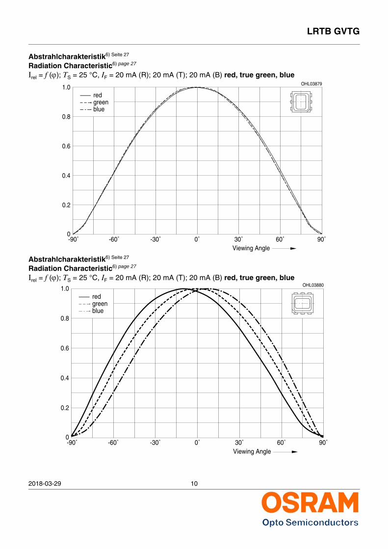
Abstrahlcharakteristik6) Seite 27
Radiation Characteristic6) page 27
Irel = f (); TS = 25 °C, IF = 20 mA (R); 20 mA (T); 20 mA (B) red, true green, blue
Abstrahlcharakteristik6) Seite 27
Radiation Characteristic6) page 27
Irel = f (); TS = 25 °C, IF = 20 mA (R); 20 mA (T); 20 mA (B) red, true green, blue
-90˚0
0.2
0.4
0.6
0.8
1.0OHL03879
Viewing Angle-60˚ -30˚ 0˚ 30˚ 60˚ 90˚
greenblue
red
red
bluegreen
0.2
0-90˚
0.6
0.4
0.8
Viewing Angle-60˚ -30˚ 0˚ 30˚ 60˚ 90˚
1.0OHL03880
LRTB GVTG
2018-03-29 11
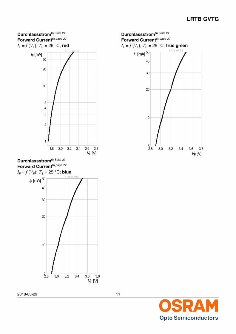
Durchlassstrom6) Seite 27
Forward Current6) page 27
IF = f (VF); TS = 25 °C; red
Durchlassstrom6) Seite 27
Forward Current6) page 27
IF = f (VF); TS = 25 °C; blue
Durchlassstrom6) Seite 27
Forward Current6) page 27
IF = f (VF); TS = 25 °C; true greenLRTB GVTG
1,8 2,0 2,2 2,4 2,6 2,8VF [V]
1
2
3
45
10
20
30IF [mA]
LRTB GVTG
2,8 3,0 3,2 3,4 3,6 3,8VF [V]
5
10
20
30
40
50IF [mA]
LRTB GVTG
2,8 3,0 3,2 3,4 3,6 3,8VF [V]
5
10
20
30
40
50IF [mA]
LRTB GVTG
2018-03-29 12
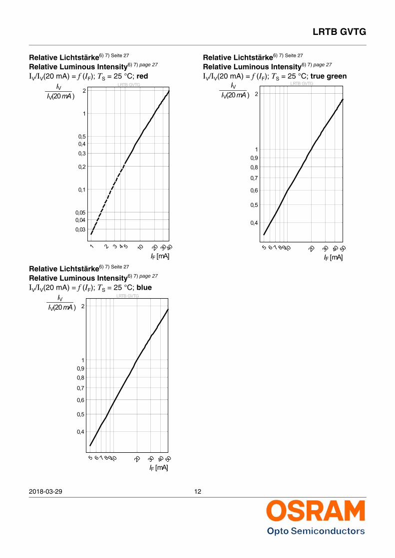
Relative Lichtstärke6) 7) Seite 27
Relative Luminous Intensity6) 7) page 27
IV/IV(20 mA) = f (IF); TS = 25 °C; red
Relative Lichtstärke6) 7) Seite 27
Relative Luminous Intensity6) 7) page 27
IV/IV(20 mA) = f (IF); TS = 25 °C; blue
Relative Lichtstärke6) 7) Seite 27
Relative Luminous Intensity6) 7) page 27
IV/IV(20 mA) = f (IF); TS = 25 °C; true greenLRTB GVTG
1 2 3 4 5 10 20 30 40IF [mA]
0,03
0,040,05
0,1
0,2
0,3
0,40,5
1
2IV
IV(20mA )
LRTB GVTG
5 6 7 8 910 20 30 40 50IF [mA]
0,4
0,5
0,6
0,7
0,80,9
1
2IV
IV(20mA )
LRTB GVTG
5 6 7 8 910 20 30 40 50IF [mA]
0,4
0,5
0,6
0,7
0,80,9
1
2IV
IV(20mA )
LRTB GVTG
2018-03-29 13
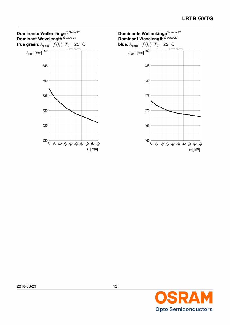
Dominante Wellenlänge6) Seite 27
Dominant Wavelength6) page 27
true green, dom = f (IF); TS = 25 °C
Dominante Wellenlänge6) Seite 27
Dominant Wavelength6) page 27
blue, dom = f (IF); TS = 25 °CLRTB GVTG
5 10 15 20 25 30 35 40 45 50IF [mA]
520
525
530
535
540
545
550λ dom [nm]LRTB GVTG
5 10 15 20 25 30 35 40 45 50IF [mA]
460
465
470
475
480
485
490λ dom [nm]
LRTB GVTG
2018-03-29 14
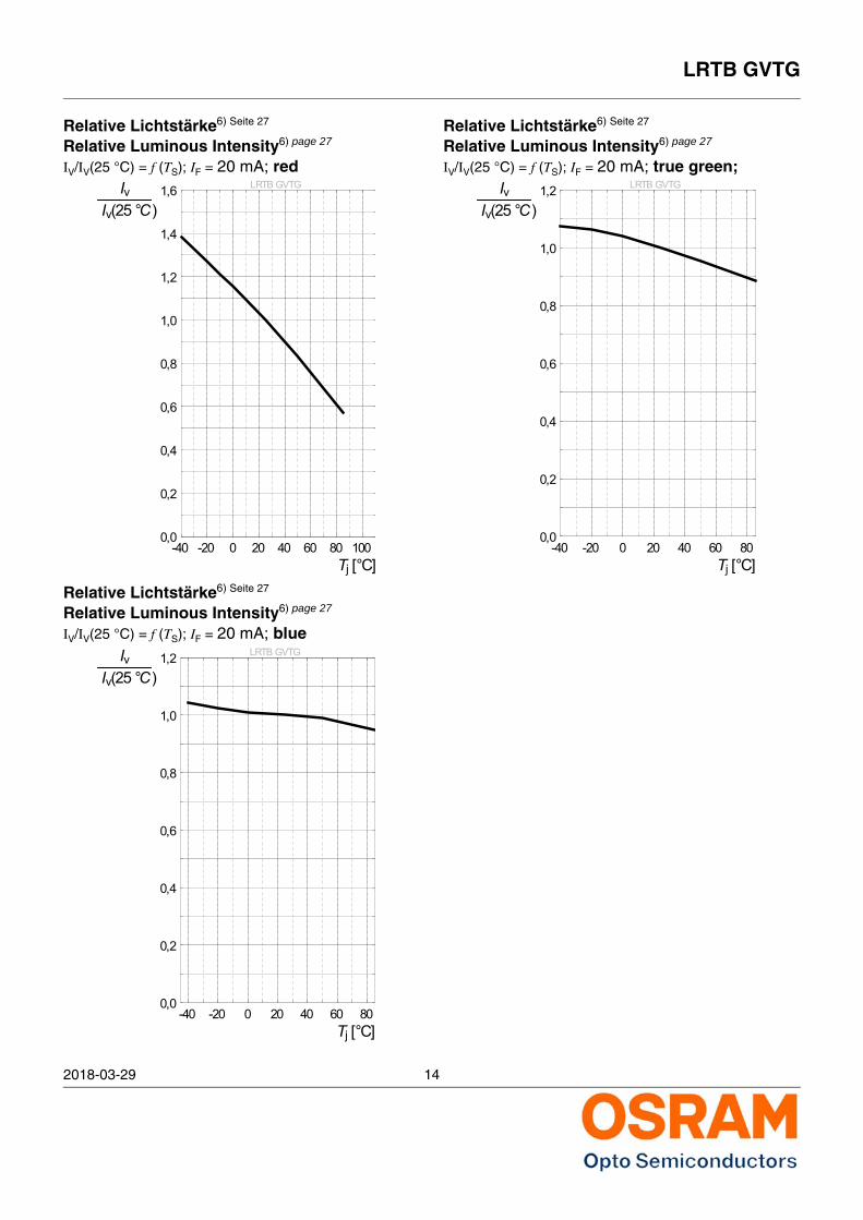
Relative Lichtstärke6) Seite 27
Relative Luminous Intensity6) page 27
IV/IV(25 °C) = f (TS); IF = 20 mA; red
Relative Lichtstärke6) Seite 27
Relative Luminous Intensity6) page 27
IV/IV(25 °C) = f (TS); IF = 20 mA; blue
Relative Lichtstärke6) Seite 27
Relative Luminous Intensity6) page 27
IV/IV(25 °C) = f (TS); IF = 20 mA; true green;LRTB GVTG
-40 -20 0 20 40 60 80 100Tj [°C]
0,0
0,2
0,4
0,6
0,8
1,0
1,2
1,4
1,6Iv Iv(25 °C)
LRTB GVTG
-40 -20 0 20 40 60 80Tj [°C]
0,0
0,2
0,4
0,6
0,8
1,0
1,2Iv Iv(25 °C)
LRTB GVTG
-40 -20 0 20 40 60 80Tj [°C]
0,0
0,2
0,4
0,6
0,8
1,0
1,2Iv Iv(25 °C)
LRTB GVTG
2018-03-29 15
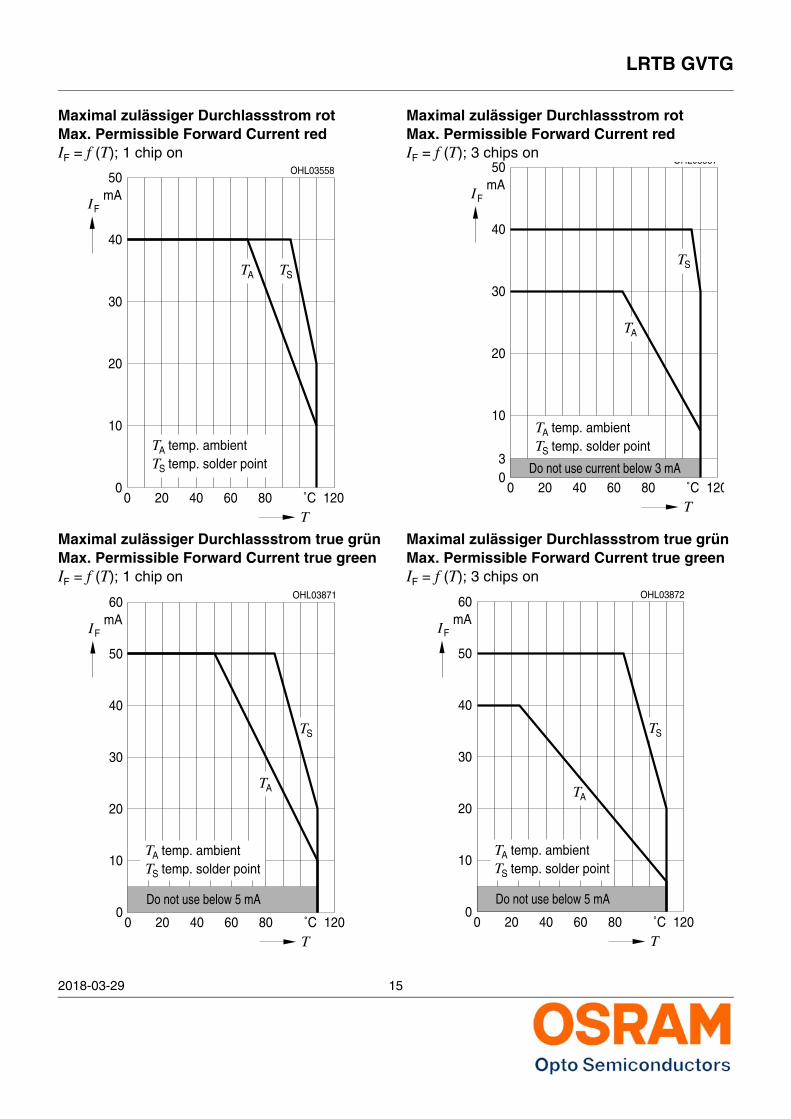
Maximal zulässiger Durchlassstrom rotMax. Permissible Forward Current redIF = f (T); 1 chip on
Maximal zulässiger Durchlassstrom true grünMax. Permissible Forward Current true greenIF = f (T); 1 chip on
Maximal zulässiger Durchlassstrom rotMax. Permissible Forward Current redIF = f (T); 3 chips on
Maximal zulässiger Durchlassstrom true grünMax. Permissible Forward Current true greenIF = f (T); 3 chips on
00
˚CT
IFmA
OHL03558
20 40 60 80 120
10
20
30
40
50
TSTA
temp. ambientTtemp. solder pointST
A
30
00
10
20
Do not use below 5 mA
temp. solder point
604020
temp. ambientTS
TA
12080 ˚CT
TA
40
FI
50
mA60
S
OHL03871
T
Do not use current below 3 mA0
0
10
20
1208020 40 60 ˚CT
T temp. solder pointS
T temp. ambientA
AT
30
IF
40
mA50
TS
OHL03557
3
30
00
10
20
temp. solder point
Do not use below 5 mA
604020
temp. ambientTS
TA
AT
12080 ˚CT
40
FI
50
mA60
S
OHL03872
T
LRTB GVTG
2018-03-29 16
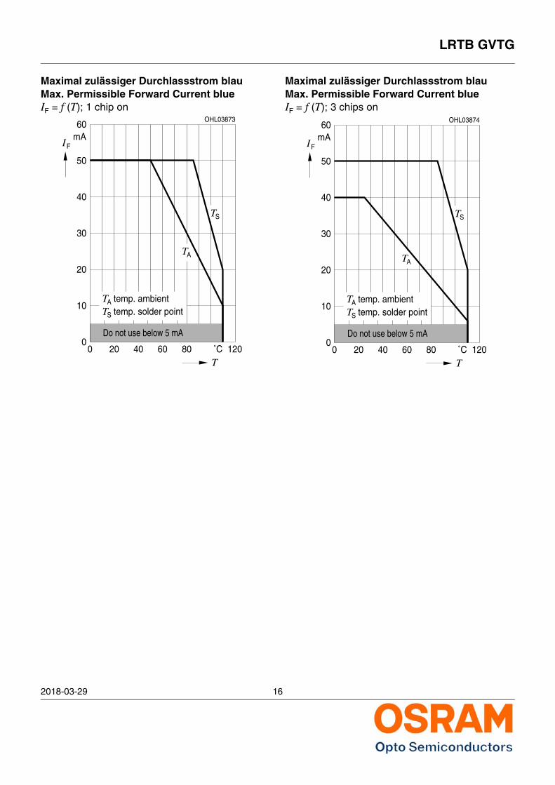
Maximal zulässiger Durchlassstrom blauMax. Permissible Forward Current blueIF = f (T); 1 chip on
Maximal zulässiger Durchlassstrom blauMax. Permissible Forward Current blueIF = f (T); 3 chips on
30
00
10
20
temp. solder point
Do not use below 5 mA
604020
temp. ambientTS
TA
12080 ˚CT
TA
40
FI
50
mA60
S
OHL03873
T
30
00
10
20
Do not use below 5 mA
temp. solder point
604020
temp. ambientTS
TA
AT
12080 ˚CT
40
FI
50
mA60
S
OHL03874
T
LRTB GVTG
2018-03-29 17
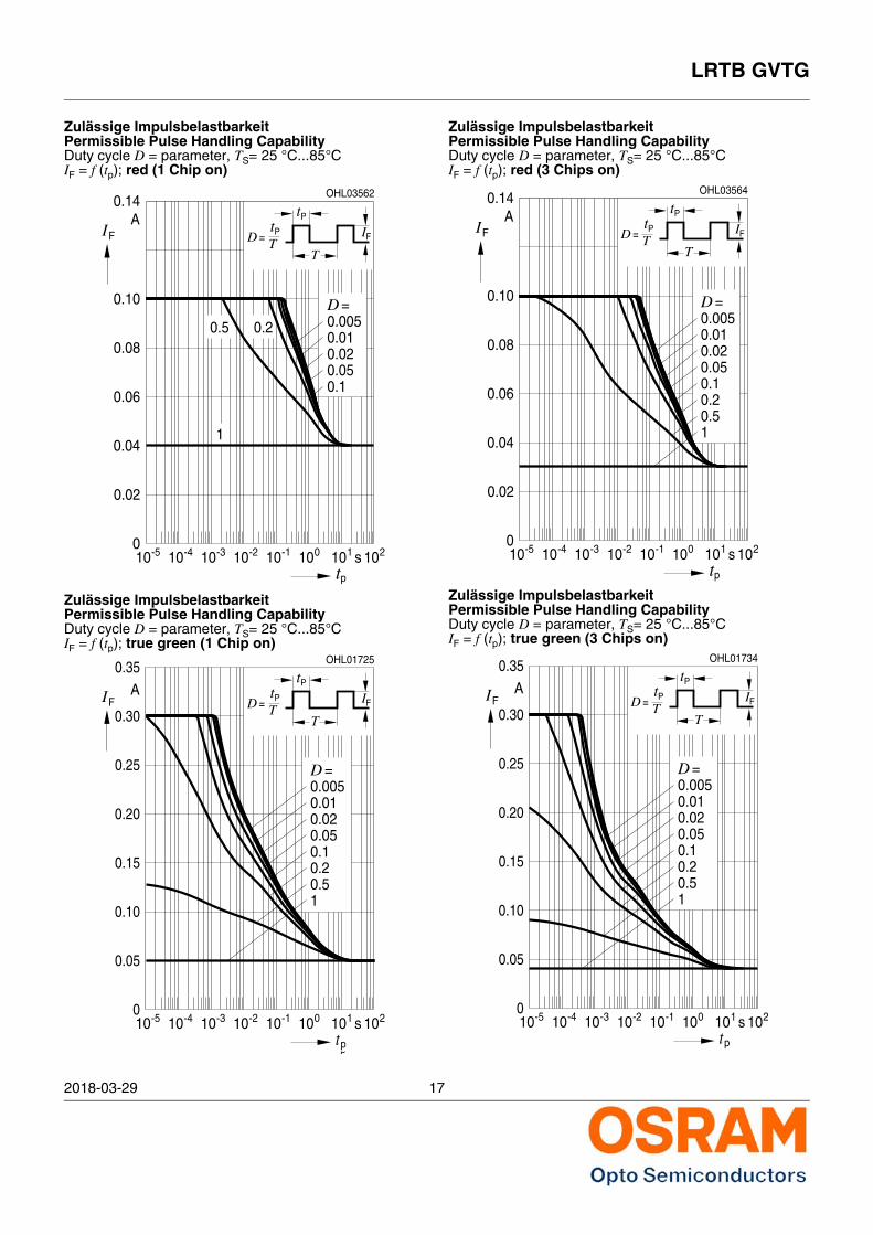
Zulässige Impulsbelastbarkeit Permissible Pulse Handling CapabilityDuty cycle D = parameter, TS= 25 °C...85°CIF = f (tp); red (1 Chip on)
Zulässige Impulsbelastbarkeit Permissible Pulse Handling CapabilityDuty cycle D = parameter, TS= 25 °C...85°CIF = f (tp); true green (1 Chip on)
Zulässige Impulsbelastbarkeit Permissible Pulse Handling CapabilityDuty cycle D = parameter, TS= 25 °C...85°CIF = f (tp); red (3 Chips on)
Zulässige ImpulsbelastbarkeitPermissible Pulse Handling CapabilityDuty cycle D = parameter, TS= 25 °C...85°CIF = f (tp); true green (3 Chips on)
0-5
FIA
tp
s
OHL03562
-410 -310 -210 -110 010 110 21010
0.01
0.1
0.020.05
0.005D =
0.20.5
1
0.02
0.04
0.06
0.08
0.10
0.14
T
tTD = P
PtIF
0-5
FIA
tp
s
OHL03566
-410 -310 -210 -110 010 110 21010
0.01
0.1
0.020.05
0.005D =
0.20.5
1
0.02
0.04
0.06
0.08
0.10
0.14
T
tTD = P
PtIF
10100
-2-3-4-5 1010 10
FI APt=D T
210-1 10tp
10 s 10
OHL01725
T
tP
IF
0.05
0.10
0.15
0.20
0.25
0.35
0.02
0.50.2
0.050.1
D =0.0050.01
1
0.30
0-5
FIA
tp
s
OHL03564
-410 -310 -210 -110 010 110 21010
0.01
0.1
0.020.05
0.005D =
0.02
0.04
0.06
0.08
0.10
0.14
T
tTD = P
PtIF
0.20.51
0-5
FIA
tp
s
OHL03568
-410 -310 -210 -110 010 110 21010
0.01
0.1
0.020.05
0.005D =
0.02
0.04
0.06
0.08
0.10
0.14
T
tTD = P
PtIF
0.20.51
1010 -2-3-4-5 1010 10
FI Pt=D T
210-1 10tp
10 s 10
OHL01734
T
tP
IF
0
0.05
0.10
0.15
0.20
0.25
0.30
0.35
A
0.05
10.5
0.10.2
0.010.005
=
0.02
D
LRTB GVTG
2018-03-29 18
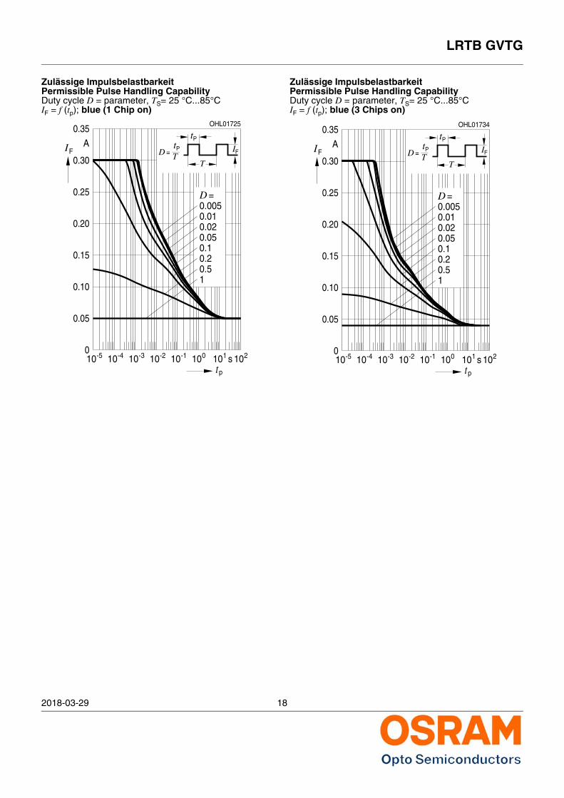
Zulässige Impulsbelastbarkeit Permissible Pulse Handling CapabilityDuty cycle D = parameter, TS= 25 °C...85°CIF = f (tp); blue (1 Chip on)
Zulässige Impulsbelastbarkeit Permissible Pulse Handling CapabilityDuty cycle D = parameter, TS= 25 °C...85°CIF = f (tp); blue (3 Chips on)
0-5
FIA
tp
s
OHL03570
-410 -310 -210 -110 010 110 21010
0.01
0.1
0.020.05
0.005D =
0.02
0.04
0.06
0.08
0.10
0.14
T
tTD = P
PtIF
0.20.51
10100
-2-3-4-5 1010 10
FI APt=D T
210-1 10tp
10 s 10
OHL01725
T
tP
IF
0.05
0.10
0.15
0.20
0.25
0.35
0.02
0.50.2
0.050.1
D =0.0050.01
1
0.30
0-5
FIA
tp
s
OHL03572
-410 -310 -210 -110 010 110 21010
0.01
0.1
0.020.05
0.005D =
0.02
0.04
0.06
0.08
0.10
0.14
T
tTD = P
PtIF
0.20.51
1010 -2-3-4-5 1010 10
FI Pt=D T
210-1 10tp
10 s 10
OHL01734
T
tP
IF
0
0.05
0.10
0.15
0.20
0.25
0.30
0.35
A
0.05
10.5
0.10.2
0.010.005
=
0.02
D
LRTB GVTG
2018-03-29 19
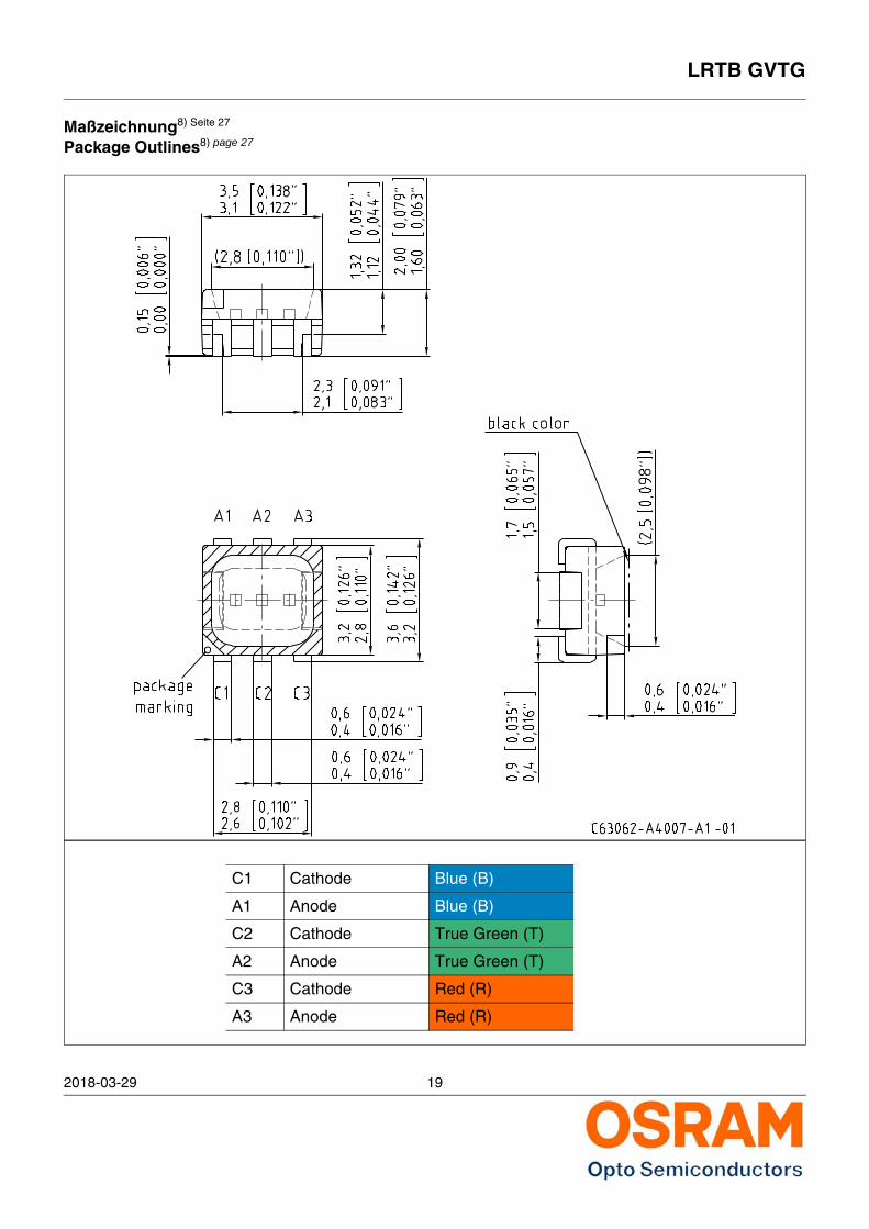
Maßzeichnung8) Seite 27
Package Outlines8) page 27
C1 Cathode Blue (B)
A1 Anode Blue (B)
C2 Cathode True Green (T)
A2 Anode True Green (T)
C3 Cathode Red (R)
A3 Anode Red (R)
2018-03-29 20
LRTB GVTG
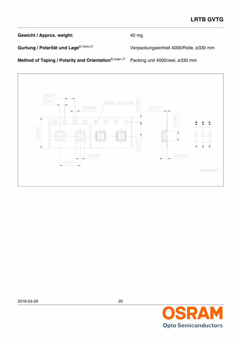
Gewicht / Approx. weight: 40 mg
Gurtung / Polarität und Lage8) Seite 27 Verpackungseinheit 4000/Rolle, ø330 mm
Method of Taping / Polarity and Orientation8) page 27 Packing unit 4000/reel, ø330 mm
LRTB GVTG
2018-03-29 21
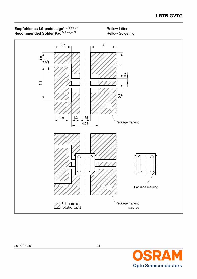
Empfohlenes Lötpaddesign8) 9) Seite 27 Reflow LötenRecommended Solder Pad8) 9) page 27 Reflow Soldering
OHPY3868
Package marking
Package markingSolder resist(Lötstop Lack)
2.7 41.
8
0.4
5.1
4
0.4
0.7
1.651.32.3
4.25
Package marking
2018-03-29 22
LRTB GVTG
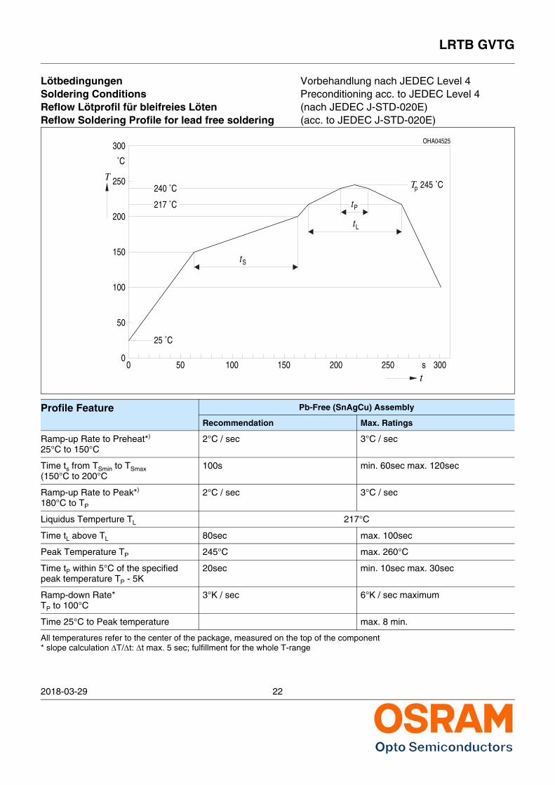
Lötbedingungen Vorbehandlung nach JEDEC Level 4Soldering Conditions Preconditioning acc. to JEDEC Level 4Reflow Lötprofil für bleifreies Löten (nach JEDEC J-STD-020E)Reflow Soldering Profile for lead free soldering (acc. to JEDEC J-STD-020E)
Profile Feature Pb-Free (SnAgCu) Assembly
Recommendation Max. Ratings
Ramp-up Rate to Preheat*)
25°C to 150°C2°C / sec 3°C / sec
Time ts from TSmin to TSmax(150°C to 200°C
100s min. 60sec max. 120sec
Ramp-up Rate to Peak*)
180°C to TP
2°C / sec 3°C / sec
Liquidus Temperture TL 217°C
Time tL above TL 80sec max. 100sec
Peak Temperature TP 245°C max. 260°C
Time tP within 5°C of the specified peak temperature TP - 5K
20sec min. 10sec max. 30sec
Ramp-down Rate*TP to 100°C
3°K / sec 6°K / sec maximum
Time 25°C to Peak temperature max. 8 min.
All temperatures refer to the center of the package, measured on the top of the component* slope calculation T/t: t max. 5 sec; fulfillment for the whole T-range
00
s
OHA04525
50
100
150
200
250
300
50 100 150 200 250 300t
T
˚C
St
t
Pt
Tp240 ˚C
217 ˚C
245 ˚C
25 ˚C
L
LRTB GVTG
2018-03-29 23
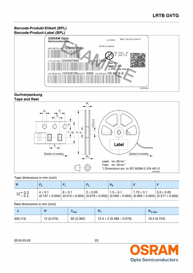
Barcode-Produkt-Etikett (BPL)Barcode-Product-Label (BPL)
GurtverpackungTape and Reel
Tape dimensions in mm (inch)
W P0 P1 P2 D0 E F
4 0.1(0.157 0.004)
8 0.1(0.315 0.004)
2 0.05(0.079 0.002)
1.5 0.1(0.059 0.004)
1.75 0.1(0.069 0.004)
5.5 0.05(0.217 0.002)
Reel dimensions in mm (inch)
A W Nmin W1 W2 max
330 (13) 12 (0.472) 60 (2.362) 12.4 + 2 (0.488 0.079) 18.4 (0.724)
Sample
OHA32043
(G) GROUP:
Lot Number(1T) LOT NO: (9D) D/C: Date Code
(X) PROD NO: Product Code
(6P) BATCH NO: Batch Number
Lxxx xxxx
Product Name
RoHS Compliant
Bin1: Bin Information Color 1Bin2: Bin Information Color 2Bin3: Bin Information Color 3
ML2
Temp ST245 C RT
Additional TEXT
R077 DEMY
PACKVAR: Packing Type
Product Quantity per Reel(Q)QTY:
SemiconductorsOSRAM Opto
Wavelength Group
Forward Voltage Group
Brightness Group
X-X-X+X-X-X+X-X-XColor 1 Color 2 Color 3
Bar Code
Bar Code
Bar CodeOHA04563
(G) GROUP:
1234567890(1T) LOT NO: (9D) D/C: 1234
(X) PROD NO: 123456789
(6P) BATCH NO: 1234567890
LX XXXX
RoHS Compliant
BIN1: XX-XX-X-XXX-X
MLX
Temp STXXX °C X
Pack: RXX
DEMY XXX
X_X123_1234.1234 X
9999(Q)QTY:
SemiconductorsOSRAM Opto
XX-XX-X-XLEXXPLELLXX
234.1234 X
X-X-XLLLLLLPLXXXXXX
12123
XXXX
MPLXX
X
X_X123_1
XX-XX
MPLPack: RXPack: RX
DEMY DEMY
MP4MPAMPMMMAMMAMMD) D/CD) D/C 234234MMMMM3PLPack: R
DEMY
AMMMAMAMD/MPMMM: 123AMAMAAM(9D
XAAAXAAXAXXAXEXAEXEXEXXXXAXXEXEXX78907890EXXXXXXEXEXAEEEXEXEEXXEEXEEXEXEX: 1234567
rEEEEEEEEENO:NO: 234234EXorsorsXAX890
X
RX
DEMY
12
D) D/C: 234(
7890NO: 234
p o
XXX
_123
XX-
Pack: R
DEMY
tors
D0
2P
P0
1P
WFE
Direction of unreeling
N
W1
2W
A
OHAY0324
Label
Leader:Trailer:
13.0
Direction of unreeling
±0.2
5
min. 160 mm *min. 400 mm *
*) Dimensions acc. to IEC 60286-3; EIA 481-D
12+ 0.3– 0.1
2018-03-29 24
LRTB GVTG
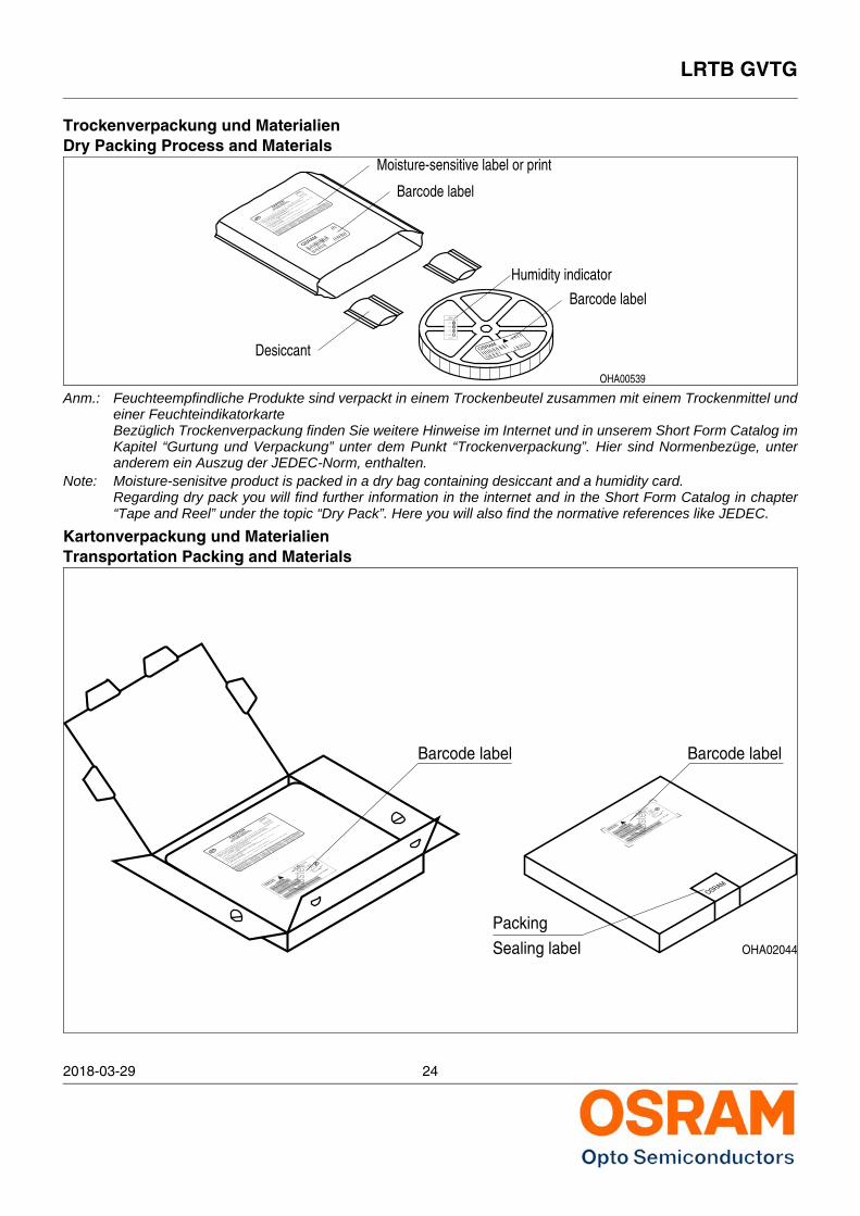
Trockenverpackung und MaterialienDry Packing Process and Materials
Anm.: Feuchteempfindliche Produkte sind verpackt in einem Trockenbeutel zusammen mit einem Trockenmittel undeiner FeuchteindikatorkarteBezüglich Trockenverpackung finden Sie weitere Hinweise im Internet und in unserem Short Form Catalog imKapitel “Gurtung und Verpackung” unter dem Punkt “Trockenverpackung”. Hier sind Normenbezüge, unteranderem ein Auszug der JEDEC-Norm, enthalten.
Note: Moisture-senisitve product is packed in a dry bag containing desiccant and a humidity card.Regarding dry pack you will find further information in the internet and in the Short Form Catalog in chapter“Tape and Reel” under the topic “Dry Pack”. Here you will also find the normative references like JEDEC.
Kartonverpackung und MaterialienTransportation Packing and Materials
OHA00539
OSRAM
Moisture-sensitive label or print
Barcode label
Desiccant
Humidity indicator
Barcode label
OSRAM
Please check the HIC immidiately afterbag opening.
Discard if circles overrun.Avoid metal contact.
WET
Do not eat.
Comparatorcheck dot
parts still adequately dry.
examine units, if necessary
examine units, if necessary
5%
15%
10%bake units
bake units
If wet,
change desiccant
If wet,
Humidity IndicatorMIL-I-8835
If wet,
Mois
ture
Level 3
Flo
or tim
e 168 H
ours
Mois
ture
Level 6
Floor
time
6 H
ours
a) H
umid
ity In
dicato
r C
ard is
> 1
0% w
hen read a
t 23 ˚
C ±
5 ˚C
, or
reflo
w, v
apor-phase re
flow
, or equiv
alent p
rocessin
g (peak p
ackage
2. Afte
r th
is b
ag is o
pened, devic
es that w
ill b
e subje
cted to
infra
red
1. Shelf
life in
seale
d bag: 2
4 month
s at <
40 ˚
C a
nd < 9
0% re
lativ
e hum
idity
(R
H).
Mois
ture
Level 5
a
at facto
ry c
onditions o
f
(if b
lank, s
eal date
is id
entical w
ith d
ate c
ode).
a) M
ounted w
ithin
b) Sto
red a
t
body te
mp.
3. Devic
es require
bakin
g, befo
re m
ounting, i
f:
Bag s
eal date
Mois
ture
Level 1
Mois
ture
Level 2
Mois
ture
Level 2
a4. I
f bakin
g is requir
ed,
b) 2a o
r 2b is
not m
et.
Date
and ti
me o
pened:
refe
rence IP
C/J
ED
EC
J-S
TD
-033 fo
r bake p
roce
dure.
Flo
or tim
e see b
elow
If bla
nk, see b
ar code la
bel
Flo
or tim
e > 1
Year
Flo
or tim
e 1
Year
Floor
time
4 W
eeks10%
RH
.
_<
Mois
ture
Level 4
Mois
ture
Level 5
˚C).
OPTO S
EMIC
ONDUCTO
RS
MO
ISTURE S
ENSITIV
E
This b
ag conta
ins
CAUTION
Flo
or tim
e 72 H
ours
Flo
or tim
e 48 H
ours
Flo
or tim
e 24 H
ours
30 ˚C
/60%
RH
.
_<
LE
VE
L
If bla
nk, see
bar code la
bel
OHA02044
PACKVAR:
R077Additional TEXT
P-1+Q-1
Multi TOPLED
Muste
r
OSRAM Opto
Semiconductors
(6P) BATCH NO:
(X) PROD NO:
10
(9D) D/C:
11(1T) LOT NO:
210021998
123GH1234
024 5
(Q)QTY: 2000
0144
(G) GROUP:
260 C RT240 C R
3
220 C R
MLBin3:Bin2: Q
-1-20
Bin1: P-1-20
LSY T6762
2a
Temp ST
R18DEMY
PACKVAR:
R077Additional TEXT
P-1+Q-1
Multi TOPLED
Muste
r
OSRAM Opto
Semiconductors
(6P) BATCH NO:
(X) PROD NO:
10
(9D) D/C:
11(1T) LOT NO:
210021998
123GH1234
024 5
(Q)QTY: 2000
0144
(G) GROUP:
260 C RT240 C R
3
220 C R
MLBin3:Bin2: Q
-1-20
Bin1: P-1-20
LSY T6762
2a
Temp ST
R18DEMY
OSRAM
Packing
Sealing label
Barcode label
Mois
ture
Level 3
Flo
or tim
e 168 H
ours
Mois
ture
Level 6
Flo
or tim
e 6
Hours
a) H
umid
ity In
dicato
r C
ard is
> 1
0% w
hen read a
t 23 ˚
C ±
5 ˚C
, or
reflo
w, v
apor-phase r
eflow
, or e
quivale
nt pro
cessing (p
eak package
2. Afte
r th
is b
ag is o
pened,
devices th
at will
be s
ubjecte
d to in
frare
d
1. Shelf
life in
seale
d bag: 2
4 month
s at <
40 ˚
C a
nd < 9
0% rela
tive h
umid
ity (R
H).
Mois
ture
Level 5
a
at facto
ry c
onditions o
f
(if b
lank, s
eal date
is id
entical w
ith d
ate c
ode).
a) M
ounted w
ithin
b) S
tore
d at
body te
mp.
3. Devic
es require
bakin
g, befo
re m
ounting, i
f:
Bag s
eal date
Mois
ture
Level 1
Mois
ture
Level 2
Mois
ture
Level 2
a4. If b
aking is
require
d,
b) 2a o
r 2b is
not m
et.
Date
and ti
me o
pened:
refe
rence IP
C/J
ED
EC
J-S
TD
-033 fo
r bake p
rocedure
.
Floor
time s
ee belo
w
If bla
nk, see b
ar code la
bel
Flo
or tim
e > 1
Year
Floor
time
1 Y
ear
Flo
or tim
e 4
Weeks10%
RH
.
_<
Mois
ture
Level 4
Mois
ture
Level 5
˚C).
OPTO
SEM
ICONDUCTO
RS
MO
ISTURE S
ENSITIV
E
This b
ag conta
ins
CAUTION
Flo
or tim
e 72 H
ours
Flo
or tim
e 48 H
ours
Flo
or tim
e 24 H
ours
30 ˚C
/60%
RH
.
_<
LE
VE
L
If bla
nk, see
bar code la
bel
Barcode label
LRTB GVTG
2018-03-29 25
Augensicherheitsbewertung
Wegen der Streichung der LED aus der IEC 60825 erfolgt die Bewertung der Augensicherheit nach demStandard IEC 62471:2006 ("photobiological safety of lamps and lamp systems")Im Risikogruppensystem dieser CIE- Norm erfüllen die in diesem Datenblatt angegebenen LED die"exempt"- Gruppe (die die sich im "sichtbaren" Spektralbereich auf eine Expositionsdauer von 10000 sbezieht). Unter realen Umständen (für Expositionsdauer, Augenpupille, Betrachtungsabstand) gehtdamit von diesen Bauelementen keinerlei Augengefährdung aus. Grundsätzlich sollte jedoch erwähnt werden, dass intensive Lichtquellen durch ihre Blendwirkung einhohes sekundäres Gefahrenpotenzial besitzen. Wie nach dem Blick in andere helle Lichtquellen (z.B.Autoscheinwerfer) auch, können temporär eingeschränktes Sehvermögen und Nachbilder je nachSituation zu Irritationen, Belästigungen, Beeinträchtigungen oder sogar Unfällen führen.
Eye safety advice
Due to the cancellation of the LED from IEC 60825, the evaluation of eye safety occurs according to thestandard IEC 62471:2006 ("photobiological safety of lamps and lamp systems").Within the risk grouping system of this CIE standard, the LEDs specified in this data sheet fall into the"exempt" group (relating to devices in the visible spectrum with an exposure time of 10000 s). Under realcircumstances (for exposure time, eye pupils, observation distance), it is assumed that noendangerment to the eye exists from these devices.
As a matter of principle, however, it should be mentioned that intense light sources have a highsecondary exposure potential due to their blinding effect. As is also true when viewing other bright lightsources (e.g. headlights), temporary reduction in visual acuity and afterimages can occur, leading toirritation, annoyance, visual impairment, and even accidents, depending on the situation.
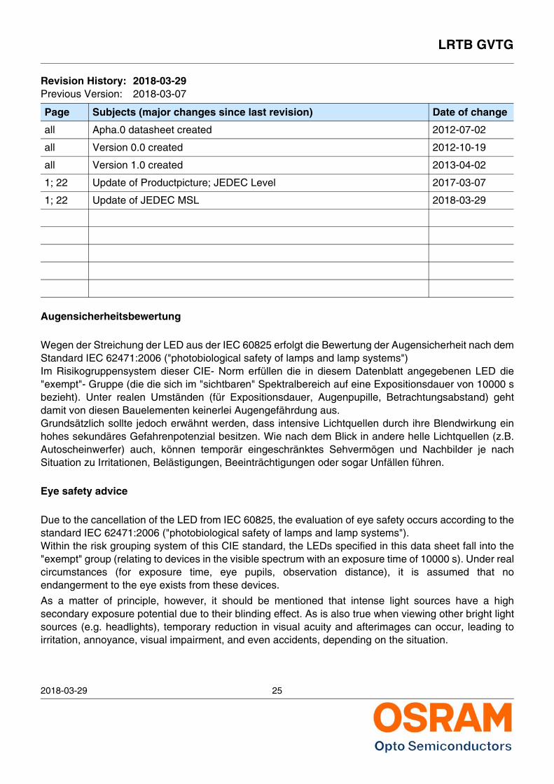
Revision History: 2018-03-29Previous Version: 2018-03-07
Page Subjects (major changes since last revision) Date of change
all Apha.0 datasheet created 2012-07-02
all Version 0.0 created 2012-10-19
all Version 1.0 created 2013-04-02
1; 22 Update of Productpicture; JEDEC Level 2017-03-07
1; 22 Update of JEDEC MSL 2018-03-29
LRTB GVTG
2018-03-29 26
Disclaimer
Bitte beachten!Lieferbedingungen und Änderungen im Designvorbehalten. Aufgrund technischer Anforderungenkönnen die Bauteile Gefahrstoffe enthalten. Fürweitere Informationen zu gewünschten Bauteilen,wenden Sie sich bitte an unseren Vertrieb.FallsSie diese Datenblatt ausgedruckt oderheruntergeladen haben, finden Sie die aktuellsteVersion im Internet.
VerpackungBenutzen Sie bitte die Ihnen bekanntenRecyclingwege. Wenn diese nicht bekannt seinsollten, wenden Sie sich bitte an dasnächstgelegene Vertriebsbüro. Wir nehmen dasVerpackungsmaterial zurück, falls dies vereinbartwurde und das Material sortiert ist. Sie tragen dieTransportkosten. Für Verpackungsmaterial, dasunsortiert an uns zurückgeschickt wird oder daswir nicht annehmen müssen, stellen wir Ihnen dieanfallenden Kosten in Rechnung.
Bauteile, die in lebenserhaltenden Apparatenund Systemen eingesetzt werden, müssen fürdiese Zwecke ausdrücklich zugelassen sein!Kritische Bauteile* dürfen in lebenserhaltendenApparaten und Systemen nur dann eingesetztwerden, wenn ein schriftliches Einverständnis vonOSRAM OS vorliegt.
*) Ein kritisches Bauteil ist ein Bauteil, das inlebenserhaltenden Apparaten oder Systemeneingesetzt wird und dessen Defekt voraussichtlichzu einer Fehlfunktion dieses lebenserhaltendenApparates oder Systems führen wird oder dieScherheit oder Effektivität dieses Apparates oderSystems beeinträchtigt.**) Lebenserhaltende Apparate oder Systeme sindfür (a) die Implantierung in den menschlichenKörper oder (b) für die Lebenserhaltung bestimmt.Falls Sie versagen, kann davon ausgegangenwerden, dass die Gesundheit und das Leben desPatienten in Gefahr ist.
Disclaimer
Attention please!The information describes the type of componentand shall not be considered as assuredcharacteristics.Terms of delivery and rights to change designreserved. Due to technical requirementscomponents may contain dangerous substances. For information on the types in question pleasecontact our Sales Organization.If printed or downloaded, please find the latestversion in the Internet.PackingPlease use the recycling operators known to you.We can also help you – get in touch with yournearest sales office. By agreement we will take packing material back,if it is sorted. You must bear the costs of transport.For packing material that is returned to usunsorted or which we are not obliged to accept, weshall have to invoice you for any costs incurred.Components used in life-support devices orsystems must be expressly authorized for suchpurpose!Critical components* may only be used inlife-support devices** or systems with theexpress written approval of OSRAM OS.
*) A critical component is a component used in alife-support device or system whose failure canreasonably be expected to cause the failure of thatlife-support device or system, or to affect its safetyor the effectiveness of that device or system.
**) Life support devices or systems are intended(a)to be implanted in the human body,or(b) to supportand/or maintain and sustain human life.If they fail,it is reasonable to assume that the health and thelife of the user may be endangered.
LRTB GVTG
2018-03-29 27
Fußnoten:1) Helligkeitswerte werden während eines Strompulses einer
typischen Dauer von 25 ms, mit einer internenReproduzierbarkeit von +/- 8 % und einer erweitertenMessunsicherheit von +/- 11 % gemessen (gemäß GUMmit Erweiterungsfaktor k = 3).
2) Die LED kann kurzzeitig in Sperrichtung betrieben werden.3) RthJA ergibt sich bei Montage auf PC-Board FR 4
(Padgröße 16 mm2 je Pad)4) Die dominante Wellenlänge wird während eines
Strompulses einer typischen Dauer von 25 ms, mit einerinternen Reproduzierbarkeit von +/- 0,5 nm und einererweiterten Messunsicherheit von +/- 1 nm gemessen(gemäß GUM mit Erweiterungsfaktor k = 3).
5) Vorwärtsspannungen werden während eines Strompulseseiner typischen Dauer von 8 ms, mit einer internenReproduzierbarkeit von +/- 0,05 V und einer erweitertenMessunsicherheit von +/- 0,1 V gemessen (gemäß GUMmit Erweiterungsfaktor k=3)..
6) Wegen der besonderen Prozessbedingungen bei derHerstellung von LED können typische oder abgeleitetetechnische Parameter nur aufgrund statistischer Wertewiedergegeben werden. Diese stimmen nichtnotwendigerweise mit den Werten jedes einzelnenProduktes überein, dessen Werte sich von typischen undabgeleiteten Werten oder typischen Kennlinienunterscheiden können. Falls erforderlich, z.B. aufgrundtechnischer Verbesserungen, werden diese typischenWerte ohne weitere Ankündigung geändert.
7) Im gestrichelten Bereich der Kennlinien muss mit erhöhtenHelligkeitsunterschieden zwischen Leuchtdiodeninnerhalb einer Verpackungseinheit gerechnet werden.Dimmverhältnis im Gleichstrom-Betrieb max. 5:1 für red
8) Maße werden wie folgt angegeben: mm (inch)9) Gehäuse hält TTW-Löthitze aus nach CECC 00802
Published by OSRAM Opto Semiconductors GmbH Leibnizstraße 4, D-93055 Regensburgwww.osram-os.com© All Rights Reserved.
Remarks:1) Brightness values are measured during a current pulse of
typical 25 ms, with an internal reproducibility of +/- 8 % andan expanded uncertainty of +/- 11 % (acc. to GUM with acoverage factor of k = 3).
2) Driving the LED in reverse direction is suitable for shortterm application.
3) RthJA results from mounting on PC board FR 4(pad size 16 mm2 per pad)
4) The dominant wavelength is measured at a current pulseof typical 25 ms, with an internal reproducibility of +/- 0,5nm and an expanded uncertainty of +/- 1 nm (acc. to GUMwith a coverage factor of k=3).
5) The forward voltage is measured during a current pulse oftypical 8 ms, with an internal reproducibility of +/- 0,05 Vand an expanded uncertainty of +/- 0,1 V (acc. to GUM witha coverage factor of k=3).
6) Due to the special conditions of the manufacturingprocesses of LED, the typical data or calculatedcorrelations of technical parameters can only reflectstatistical figures. These do not necessarily correspond tothe actual parameters of each single product, which coulddiffer from the typical data and calculated correlations orthe typical characteristic line. If requested, e.g. because oftechnical improvements, these typ. data will be changedwithout any further notice.
7) In the range where the line of the graph is broken, youmust expect higher brightness differences between singleLEDs within one packing unit. Dimming range for direct current mode max. 5:1 for red
8) Dimensions are specified as follows: mm (inch)9) Package able to withstand TTW-soldering heat acc. to
CECC 00802