Embed Size (px)
Citation preview
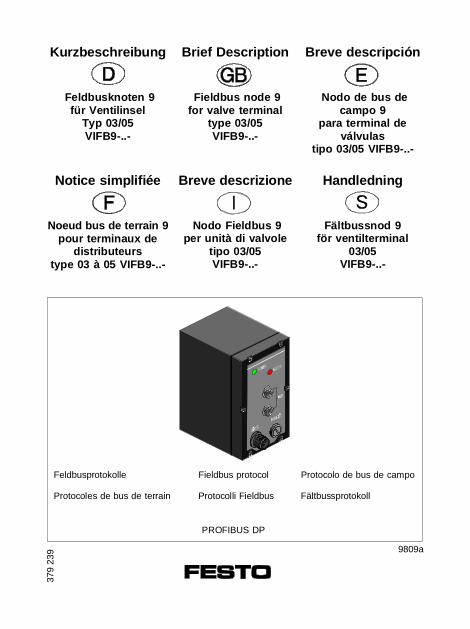
Kurzbeschreibung
Feldbusknoten 9für Ventilinsel
Typ 03/05VIFB9-..-
Brief Description
Fieldbus node 9for valve terminal
type 03/05VIFB9-..-
Notice simplifiée
Noeud bus de terrain 9pour terminaux de
distributeurstype 03 à 05 VIFB9 -..-
Breve descrizione
Nodo Fieldbus 9per unità di valvole
tipo 03/05VIFB9-..-
Handledning
Fältbussnod 9för ventilterminal
03/05VIFB9-..-
Breve descripción
Nodo de bus decampo 9
para terminal deválvulas
tipo 03/05 VIFB9 -..-
379
239
PROFIBUS DP
9809a
Feldbusprotokolle Fieldbus protocol Protocolo de bus de campo
Protocoles de bus de terrain Protocolli Fieldbus Fältbussprotokoll
Deutsch . . . . . . . . . . . . . . . . . . . . . . . . . . . . . . . . . . . . . . 3
English . . . . . . . . . . . . . . . . . . . . . . . . . . . . . . . . . . . . . . . 11
Español . . . . . . . . . . . . . . . . . . . . . . . . . . . . . . . . . . . . . 19
Français . . . . . . . . . . . . . . . . . . . . . . . . . . . . . . . . . . . . . 27
Italiano . . . . . . . . . . . . . . . . . . . . . . . . . . . . . . . . . . . . . . 35
Svenska . . . . . . . . . . . . . . . . . . . . . . . . . . . . . . . . . . . . . 43
(Festo AG & Co., D-73726 Esslingen, 1998)
VIFB9 - 03/05
9809a 2
1 Benutzerhinweise
Der Feldbusknoten 9 für die Ventilinseln Typ 03..05 ist aus-schließlich für den Einsatz als Teilnehmer am PROFIBUS DPbestimmt. Hierbei sind die angegebenen Grenzwerte der techni-schen Daten einzuhalten.
Ausführliche Informationen finden Sie in den Pneumatik-Be-schreibungen P.BE MIDI/MAXI-... und P.BE ISO-... und derElektronik-Beschreibung P.BE VIFB9-03/05....
WARNUNG:• Schalten Sie die Spannung aus, bevor Sie Steckverbinder
zusammenstecken oder trennen (Funktionsschädigung).• Verwenden Sie nur Netzteile, die eine sichere elektrische
Trennung der Betriebsspannung nach IEC 742/EN 60742/VDE 0551 mit mindestens 4 kV Isolationsfestigkeit gewährleisten (Protected Extra-Low Voltage, PELV, siehe nebenstehendes Zeichen). Schaltnetzteile sind zulässig, wenn sie die sichere Trennungim Sinne der EN 60950/VDE 0805 gewährleisten.
• Schließen Sie einen Erdleiter mit ausreichendem Leitungs-querschnitt an den mit gekennzeichneten Anschluß an, wenn die Ventilinsel nicht auf einem geerdeten Maschinengestell montiert ist.
HINWEIS:Nehmen Sie nur eine komplett montierte und verdrahteteVentilinsel in Betrieb.
Deu
tsch
VIFB9 - 03/05
9809a 3
2 Konfiguration
HINWEIS:Beim Öffnen des Knotens: Verbindende Kabel verhinderndas komplette Abheben des Deckels.
VORSICHT:Die Komponenten der Ventilinsel enthalten elektronisch ge-fährdete Bauelemente. Berühren der Kontaktflächen anSteckverbindungen und Mißachtung der Handhabungsvor-schriften für elektrostatisch gefährdete Bauelemente könnendie Komponenten zerstören.
Gehen Sie beim Konfigurieren wie folgt vor:1. Betriebsspannung abschalten.2. Knoten öffnen (Schrauben sind verlierbar).3. Feldbusadresse einstellen.4. Protokoll einstellen.5. Knoten schließen.6. Ist die Ventilinsel letzter Feldbusteilnehmer, muß der
Abschlußwiderstand zugeschaltet werden.
Feldbusbaudrate
Die Festo-Ventilinsel Typ 03/05 stellt sich automatisch auf dierichtige Baudrate ein.
Deu
tsch
VIFB9 - 03/05
4 9809a
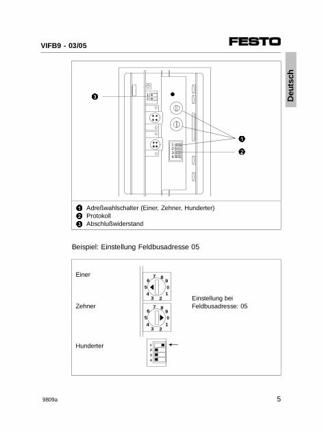
1
2
3
Adreßwahlschalter (Einer, Zehner, Hunderter)ProtokollAbschlußwiderstand
Beispiel: Einstellung Feldbusadresse 05
Einer
Einstellung bei
Zehner Feldbusadresse: 05
Hunderter
AAAAAAAA
AAAAAA
AAAAAA
AAAAAA
1234
AAAA
AAAA
12
1
2
3
12
3
4
65
2
7 8
01
34
9
65
2
7 8
01
34
9
Deu
tsch
VIFB9 - 03/05
9809a 5
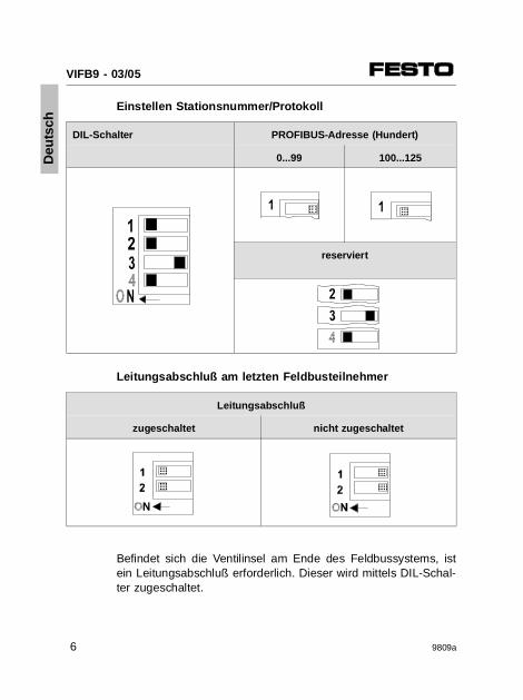
Einstellen Stationsnummer/Protokoll
DIL-Schalter PROFIBUS-Adresse (Hundert)
0...99 100...125
reserviert
Leitungsabschluß am letzten Feldbusteilnehmer
Leitungsabschluß
zugeschaltet nicht zugeschaltet
Befindet sich die Ventilinsel am Ende des Feldbussystems, istein Leitungsabschluß erforderlich. Dieser wird mittels DIL-Schal-ter zugeschaltet.
AAAAAA
AAAAAAAA
AAA
AAAAAA
AAAAAAAAA
AAAA
AAAA
Deu
tsch
VIFB9 - 03/05
6 9809a
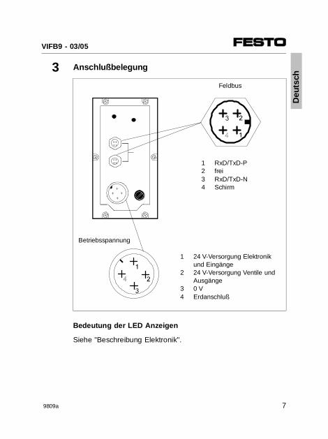
3 Anschlußbelegung
Feldbus
1 RxD/TxD-P2 frei3 RxD/TxD-N4 Schirm
Betriebsspannung
1
2
34
24 V-Versorgung Elektronikund Eingänge24 V-Versorgung Ventile undAusgänge0 VErdanschluß
Bedeutung der LED Anzeigen
Siehe "Beschreibung Elektronik".
Deu
tsch
VIFB9 - 03/05
9809a 7
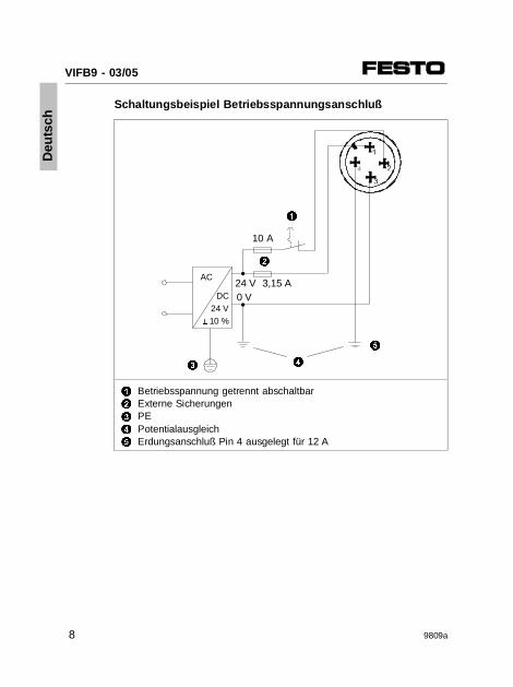
Schaltungsbeispiel Betriebsspannungsanschluß
1
2
3
4
5
Betriebsspannung getrennt abschaltbarExterne SicherungenPE Potentialausgleich Erdungsanschluß Pin 4 ausgelegt für 12 A
24 V 3,15 AAC
DC 24 V± 10 %
2
1
0 V
4
5
3
10 A
Deu
tsch
VIFB9 - 03/05
8 9809a
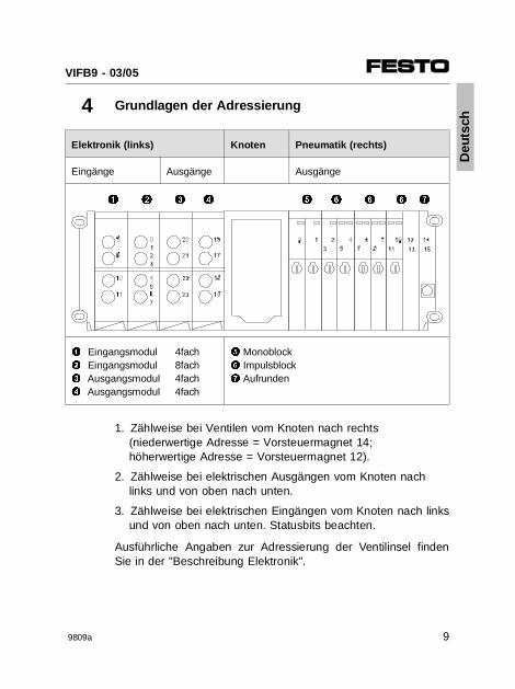
4 Grundlagen der Adressierung
Elektronik (links) Knoten Pneumatik (rechts)
Eingänge Ausgänge Ausgänge
1 Eingangsmodul 4fach2 Eingangsmodul 8fach3 Ausgangsmodul 4fach4 Ausgangsmodul 4fach
5 Monoblock6 Impulsblock7 Aufrunden
1. Zählweise bei Ventilen vom Knoten nach rechts(niederwertige Adresse = Vorsteuermagnet 14;höherwertige Adresse = Vorsteuermagnet 12).
2. Zählweise bei elektrischen Ausgängen vom Knoten nachlinks und von oben nach unten.
3. Zählweise bei elektrischen Eingängen vom Knoten nach linksund von oben nach unten. Statusbits beachten.
Ausführliche Angaben zur Adressierung der Ventilinsel findenSie in der "Beschreibung Elektronik".
1 2 3 4 5 6 76 6
Deu
tsch
VIFB9 - 03/05
9809a 9
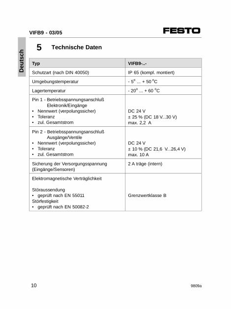
5 Technische Daten
Typ VIFB9-..-
Schutzart (nach DIN 40050) IP 65 (kompl. montiert)
Umgebungstemperatur - 5o ... + 50 oC
Lagertemperatur - 20o ... + 60 oC
Pin 1 - Betriebsspannungsanschluß Elektronik/Eingänge
• Nennwert (verpolungssicher)• Toleranz• zul. Gesamtstrom
DC 24 V± 25 % (DC 18 V...30 V)max. 2,2 A
Pin 2 - BetriebsspannungsanschlußAusgänge/Ventile
• Nennwert (verpolungssicher)• Toleranz• zul. Gesamtstrom
DC 24 V± 10 % (DC 21,6 V...26,4 V)max. 10 A
Sicherung der Versorgungsspannung (Eingänge/Sensoren)
2 A träge (intern)
Elektromagnetische Verträglichkeit
Störaussendung• geprüft nach EN 55011Störfestigkeit• geprüft nach EN 50082-2
Grenzwertklasse B
Deu
tsch
VIFB9 - 03/05
10 9809a
1 User instructions
The fieldbus node 9 for valve terminals type 03..05 is designedexclusively for use as a slave on the PROFIBUS DP. The limitvalues of the technical specifications must be observed.
Please refer to the "Pneumatics manuals" P.BE MIDI/MAXI-...and P.BE ISO-... and the "Electronics manual" P.BE VIFB9-03/05... for detailed information.
WARNING• Switch off the power supply before you connect or
disconnect plugs (danger of functional damage).• Use only power units which guarantee reliable isolation
of the operating voltages as per IEC 742/EN 60742/ VDE 0551 with at least 4 kV isolation resistance (protectedextra low voltage, PELV, see adjacent designation). Switch power packs are permitted if they guarantee reliable isolation in accordance with EN 60950/VDE 0805.
• Connect an earth conductor with sufficient cross section to the connection marked with , if the valve terminal is not fitted on an earthed machine stand.
PLEASE NOTEOnly operate a valve terminal which is completely fitted andelectrically wired.
Eng
lish
VIFB9 - 03/05
9809a 11
2 Configuration
PLEASE NOTEThe cover is connected to the internal PC boards via theoperating voltage cable. It cannot therefore be removed completely.
CAUTIONThe components of the valve terminal contain elementswhich are liable to damage by electrostatic charges. Thecomponents can also be destroyed if the contact surfaces ofplug connectors are touched, or if the regulations for hand-ling electrostatically vulnerable components are not observed.
Please observe the following when configuring:1. Switch off the operating voltage.2. Open node (screws are liable to be lost).3. Set fieldbus address.4. Set protocol.5. Close node.6. If the valve terminal to be connected is at the end of a
fieldbus line, the terminating resistor must be switched on.
Fieldbus baud rate
The Festo valve terminals type 03/05 set themselves auto-matically to the correct baud rate.
Eng
lish
VIFB9 - 03/05
12 9809a
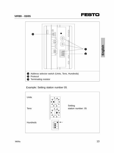
1
2
3
Address selector switch (Units, Tens, Hundreds)ProtocolTerminating resistor
Example: Setting station number 05
Units
Setting
Tens station number: 05
Hundreds
AAAAAAAA
AAAAAA
AAAAAA
AAAAAA
1234
AAAA
AAAA
12
1
2
3
12
3
4
65
2
7 8
01
34
9
65
2
7 8
01
34
9
Eng
lish
VIFB9 - 03/05
9809a 13
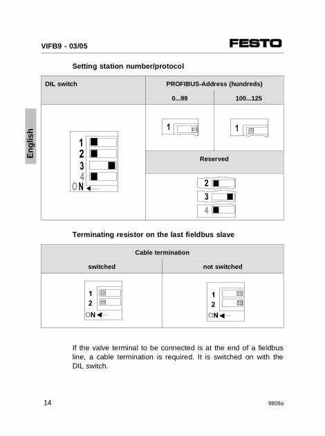
Setting station number/protocol
DIL switch PROFIBUS-Addr ess (hundreds)
0...99 100...125
Reserved
Terminating resistor on the last fieldbus slave
Cable termination
switched not switched
If the valve terminal to be connected is at the end of a fieldbusline, a cable termination is required. It is switched on with theDIL switch.
AAAAAAAAA
AAAAAA AA
AA
AAA
AAAAAA
AAAA
AAAAAA
AAAAAAAAA
Eng
lish
VIFB9 - 03/05
14 9809a
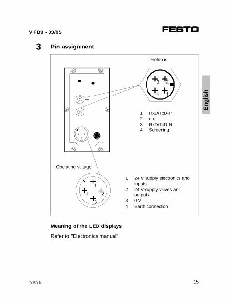
3 Pin assignment
Fieldbus
1 RxD/TxD-P2 n.c.3 RxD/TxD-N4 Screening
Operating voltage
1
2
34
24 V supply electronics andinputs24 V-supply valves and outputs0 VEarth connection
Meaning of the LED displays
Refer to "Electronics manual".
Eng
lish
VIFB9 - 03/05
9809a 15
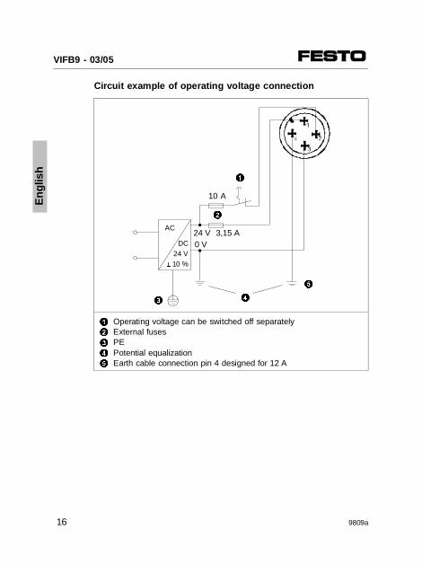
Circuit example of operating voltage connection
1
2
3
4
5
Operating voltage can be switched off separatelyExternal fusesPEPotential equalizationEarth cable connection pin 4 designed for 12 A
24 V 3,15 AAC
DC 24 V± 10 %
2
1
0 V
4
5
3
10 A
Eng
lish
VIFB9 - 03/05
16 9809a
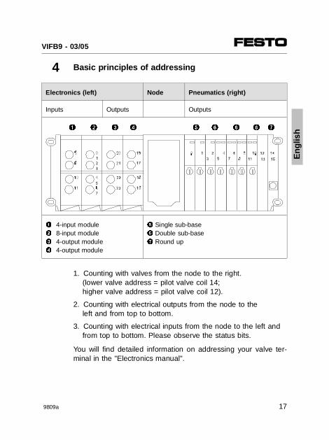
4 Basic principles of addressing
Electronics (left) Node Pneumatics (right)
Inputs Outputs Outputs
1 4-input module 2 8-input module 3 4-output module 4 4-output module
5 Single sub-base6 Double sub-base7 Round up
1. Counting with valves from the node to the right.(lower valve address = pilot valve coil 14;higher valve address = pilot valve coil 12).
2. Counting with electrical outputs from the node to theleft and from top to bottom.
3. Counting with electrical inputs from the node to the left andfrom top to bottom. Please observe the status bits.
You will find detailed information on addressing your valve ter-minal in the "Electronics manual".
1 2 3 4 5 6 76 6
Eng
lish
VIFB9 - 03/05
9809a 17
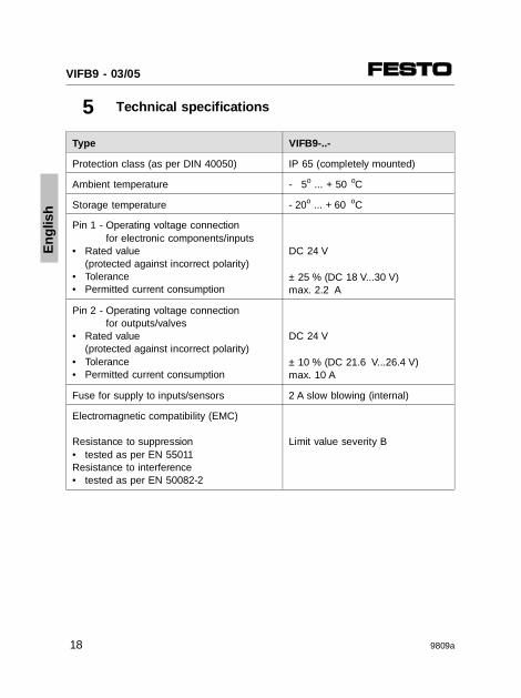
5 Technical specifications
Type VIFB9-..-
Protection class (as per DIN 40050) IP 65 (completely mounted)
Ambient temperature - 5o ... + 50 oC
Storage temperature - 20o ... + 60 oC
Pin 1 - Operating voltage connection for electronic components/inputs
• Rated value (protected against incorrect polarity)• Tolerance• Permitted current consumption
DC 24 V
± 25 % (DC 18 V...30 V)max. 2.2 A
Pin 2 - Operating voltage connection for outputs/valves
• Rated value (protected against incorrect polarity)• Tolerance• Permitted current consumption
DC 24 V
± 10 % (DC 21.6 V...26.4 V)max. 10 A
Fuse for supply to inputs/sensors 2 A slow blowing (internal)
Electromagnetic compatibility (EMC)
Resistance to suppression• tested as per EN 55011Resistance to interference• tested as per EN 50082-2
Limit value severity B
Eng
lish
VIFB9 - 03/05
18 9809a
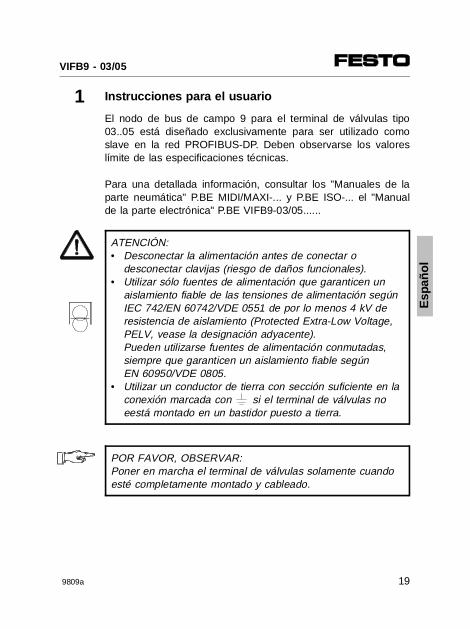
1 Instrucciones para el usuario
El nodo de bus de campo 9 para el terminal de válvulas tipo03..05 está diseñado exclusivamente para ser utilizado comoslave en la red PROFIBUS-DP. Deben observarse los valoreslímite de las especificaciones técnicas.
Para una detallada información, consultar los "Manuales de laparte neumática" P.BE MIDI/MAXI-... y P.BE ISO-... el "Manualde la parte electrónica" P.BE VIFB9-03/05......
ATENCIÓN:• Desconectar la alimentación antes de conectar o
desconectar clavijas (riesgo de daños funcionales).• Utilizar sólo fuentes de alimentación que garanticen un
aislamiento fiable de las tensiones de alimentación segúnIEC 742/EN 60742/VDE 0551 de por lo menos 4 kV de resistencia de aislamiento (Protected Extra-Low Voltage,PELV, vease la designación adyacente).Pueden utilizarse fuentes de alimentación conmutadas, siempre que garanticen un aislamiento fiable según EN 60950/VDE 0805.
• Utilizar un conductor de tierra con sección suficiente en laconexión marcada con si el terminal de válvulas no eestá montado en un bastidor puesto a tierra.
POR FAVOR, OBSERVAR:Poner en marcha el terminal de válvulas solamente cuandoesté completamente montado y cableado.
Esp
añol
VIFB9 - 03/05
9809a 19
2 Configuración
POR FAVOR, OBSERVAR:La tapa está conectada a los circuitos impresos internos através del cable de alimentación. Por ello no puede retirarsecompletamente.
PRECAUCIÓNLos componentes del terminal de válvulas contienen elemen-tos que son susceptibles de dañarse por descargas electros-táticas. Los componentes también pueden destruirse si setocan las superficies de contacto de los conectores o si nose observan las normas para la manipulación de componen-tes sensibles a las descargas electrostáticas.
Observar lo siguiente al configurar:1. Desconectar la tensión de alimentación.2. Abrir el nodo (cuidar de no perder los tornillos).3. Establecer la dirección del bus.4. Establecer el protocolo del bus de campo.5. Cerrar el nodo.6. Si el terminal se halla conectado al final de una línea
de bus, debe activarse la resistencia de terminación.
Velocidad de transmisión del bus
Los terminales de válvulas Festo 03/05 se ajustan por sí mis-mos automáticamente al valor de velocidad de transmisión co-rrecto.
Esp
añol
VIFB9 - 03/05
20 9809a
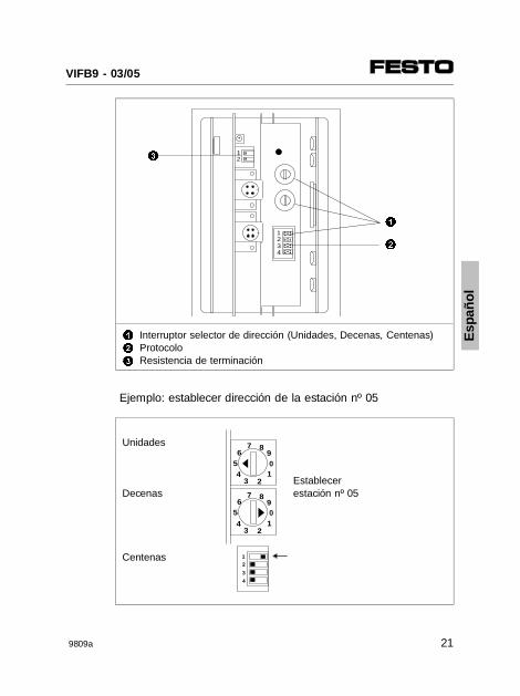
1
2
3
Interruptor selector de dirección (Unidades, Decenas, Centenas)ProtocoloResistencia de terminación
Ejemplo: establecer dirección de la estación nº 05
Unidades
Establecer
Decenas estación nº 05
Centenas
AAAAAAAA
AAAAAA
AAAAAA
AAAAAA
1234
AAAA
AAAA
12
1
2
3
12
3
4
65
2
7 8
01
34
9
65
2
7 8
01
34
9
Esp
añol
VIFB9 - 03/05
9809a 21
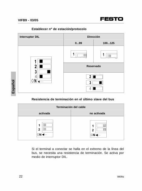
Establecer nº de estación/protocolo
Interruptor DIL Dirección
0...99 100...125
Reservado
Resistencia de terminación en el último slave del bus
Terminación del cable
activada no activada
Si el terminal a conectar se halla en el extremo de la línea delbus, se necesita una resistencia de terminación. Se activa pormedio de interruptor DIL.
AAAAAAAAA
AAAAAA AA
AA
AAA
AAAAAAAAA
AAAAAA
AAAAAA
AAAAAAAAA
Esp
añol
VIFB9 - 03/05
22 9809a
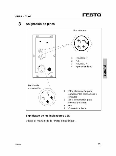
3 Asignación de pines
Bus de campo
1 RxD/TxD-P2 n.c.3 RxD/TxD-N4 Apantallamiento
Tensión de alimentación
1
2
34
24 V alimentación paracomponentes electrónicos yentradas24 V-alimentación paraválvulas y salidas0 VConexión a tierra
Significado de los indicadores LED
Véase el manual de la "Parte electrónica".
Esp
añol
VIFB9 - 03/05
9809a 23
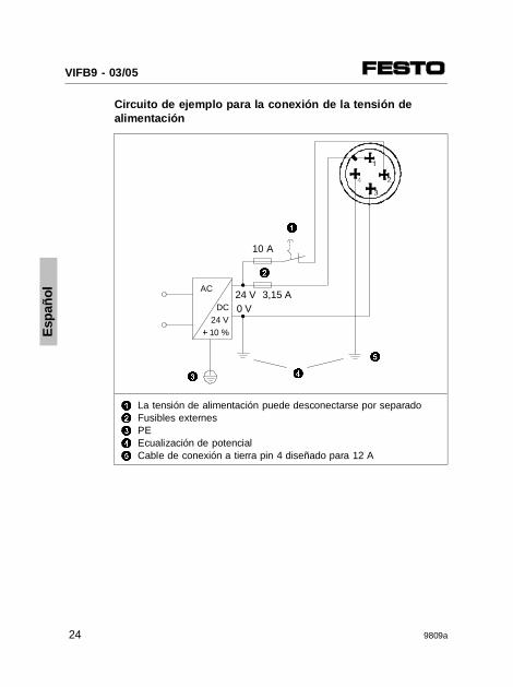
Circuito de ejemplo para la conexión de la tensión dealimentación
1
2
3
4
5
La tensión de alimentación puede desconectarse por separadoFusibles externesPEEcualización de potencialCable de conexión a tierra pin 4 diseñado para 12 A
24 V 3,15 AAC
DC 24 V± 10 %
2
1
0 V
4
5
3
10 A
Esp
añol
VIFB9 - 03/05
24 9809a
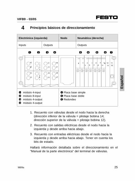
4 Principios básicos de direccionamiento
Electrónica (izquierda) Nodo Neumática (derecha)
Inputs Outputs Outputs
1 módulo 4-input2 módulo 8-input3 módulo 4-output4 módulo 4-output
5 Placa base simple6 Placa base doble7 Redondeo
1. Recuento con válvulas desde el nodo hacia la derecha(dirección inferior de la válvula = pilotaje bobina 14;dirección superior de la válvula = pilotaje bobina 12).
2. Recuento con salidas eléctricas desde el nodo hacia la izquierda y desde arriba hacia abajo.
3. Recuento con entradas eléctricas desde el nodo hacia la izquierda y desde arriba hacia abajo. Tener en cuenta losbits de estado.
Hallará información detallada sobre el direccionamiento en el"Manual de la parte electrónica" del terminal de válvulas.
1 2 3 4 5 6 76 6
Esp
añol
VIFB9 - 03/05
9809a 25
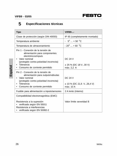
5 Especificaciones técnicas
Tipo VIFB9-..-
Clase de protección (según DIN 40050) IP 65 (completamente montado)
Temperatura ambiente - 5o ... + 50 oC
Temperatura de almacenamiento - 20o ... + 60 oC
Pin 1 - Conexión de la tensión de alimentación para componentes electrónicos/inputs
• Valor nominal(protegido contra polaridad incorrecta)
• Tolerancia• Consumo de corriente permitido
DC 24 V
± 25 % (DC 18 V...30 V)máx. 2,2 A
Pin 2 - Conexión de la tensión de alimentación para outputs/válvulas
• Valor nominal(protegido contra polaridad incorrecta)
• Tolerancia• Consumo de corriente permitido
DC 24 V
± 10 % (DC 21,6 V...26,4 V)máx. 10 A
Fusible para alimentación a inputs/sensores 2 A lento (interno)
Compatibilidad electromagnética (EMC)
Resistencia a la supresión• verificada según EN 55011Resistencia a interferencias• verificada según EN 50082-2
Valor límite severidad B
Esp
añol
VIFB9 - 03/05
26 9809a
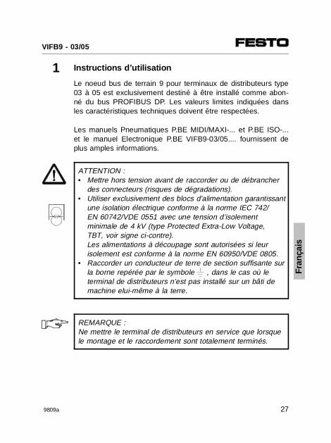
1 Instructions d’utilisation
Le noeud bus de terrain 9 pour terminaux de distributeurs type03 à 05 est exclusivement destiné à être installé comme abon-né du bus PROFIBUS DP. Les valeurs limites indiquées dansles caractéristiques techniques doivent être respectées.
Les manuels Pneumatiques P.BE MIDI/MAXI-... et P.BE ISO-...et le manuel Electronique P.BE VIFB9-03/05.... fournissent deplus amples informations.
ATTENTION :• Mettre hors tension avant de raccorder ou de débrancher
des connecteurs (risques de dégradations).• Utiliser exclusivement des blocs d’alimentation garantissant
une isolation électrique conforme à la norme IEC 742/EN 60742/VDE 0551 avec une tension d’isolement minimale de 4 kV (type Protected Extra-Low Voltage, TBT, voir signe ci-contre). Les alimentations à découpage sont autorisées si leur isolement est conforme à la norme EN 60950/VDE 0805.
• Raccorder un conducteur de terre de section suffisante surla borne repérée par le symbole , dans le cas où le terminal de distributeurs n’est pas installé sur un bâti de machine elui-même à la terre.
REMARQUE :Ne mettre le terminal de distributeurs en service que lorsquele montage et le raccordement sont totalement terminés.
Fra
nçai
s
VIFB9 - 03/05
9809a 27
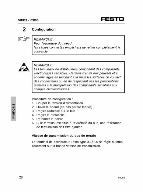
2 Configuration
REMARQUE :Pour l’ouverture du noeud : les câbles connectés empêchent de retirer complètement lecouvercle.
REMARQUE :Les terminaux de distributeurs comportent des composantsélectroniques sensibles. Certains d’entre eux peuvent êtreendommagés en touchant à la main les surfaces de contactdes connecteurs ou en ne respectant pas les prescriptionsrelatives à la manipulation des composants sensibles auxcharges électrostatiques.
Procédure de configuration :1. Couper la tension d’alimentation. 2. Ouvrir le noeud (ne pas perdre les vis). 3. Régler l’adresse sur le bus. 4. Régler le protocole.5. Refermer le noeud.6. Si le terminal est situé à l’extrémité du bus, une résistance
de terminaison doit être ajoutée.
Vitesse de transmission du bus de terrain
Le terminal de distributeur Festo type 03 à 05 se règle automa-tiquement sur la bonne vitesse de transmission.
Fra
nçai
s
VIFB9 - 03/05
28 9809a
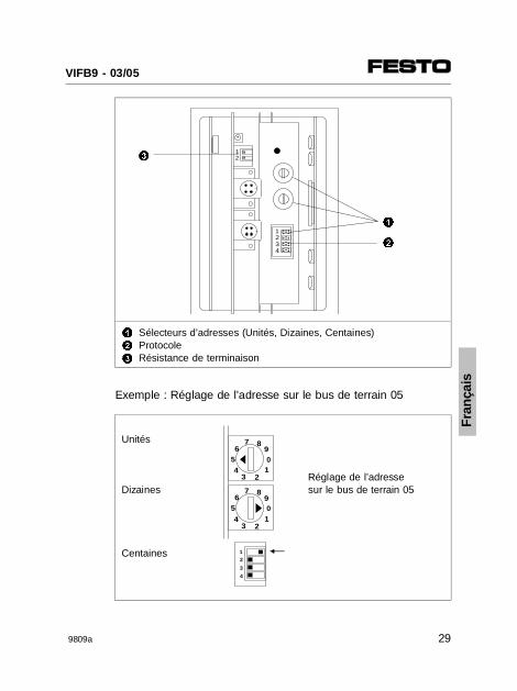
1
2
3
Sélecteurs d’adresses (Unités, Dizaines, Centaines)ProtocoleRésistance de terminaison
Exemple : Réglage de l’adresse sur le bus de terrain 05
Unités
Réglage de l’adresse
Dizaines sur le bus de terrain 05
Centaines
AAAAAAAA
AAAAAA
AAAAAA
AAAAAA
1234
AAAA
AAAA
12
1
2
3
12
3
4
65
2
7 8
01
34
9
65
2
7 8
01
34
9
Fra
nçai
s
VIFB9 - 03/05
9809a 29
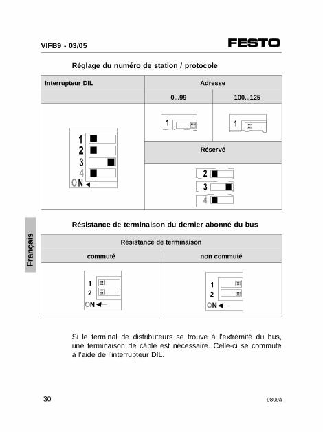
Réglage du numéro de station / protocole
Interrupteur DIL Adresse
0...99 100...125
Réservé
Résistance de terminaison du dernier abonné du bus
Résistance de terminaison
commuté non commuté
Si le terminal de distributeurs se trouve à l’extrémité du bus,une terminaison de câble est nécessaire. Celle-ci se commuteà l’aide de l’interrupteur DIL.
AAAAAAAAA
AAAAAA AA
AA
AAA
AAAAAA
AAAA
AAAAAA
AAAAAAAAA
Fra
nçai
s
VIFB9 - 03/05
30 9809a
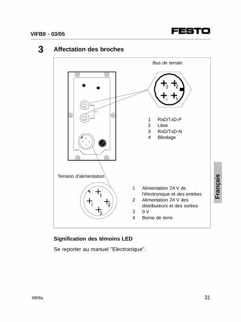
3 Affectation des broches
Bus de terrain
1 RxD/TxD-P2 Libre3 RxD/TxD-N4 Blindage
Tension d’alimentation
1
2
34
Alimentation 24 V del’électronique et des entrées Alimentation 24 V desdistributeurs et des sorties 0 VBorne de terre
Signification des témoins LED
Se reporter au manuel "Electronique".
Fra
nçai
s
VIFB9 - 03/05
9809a 31
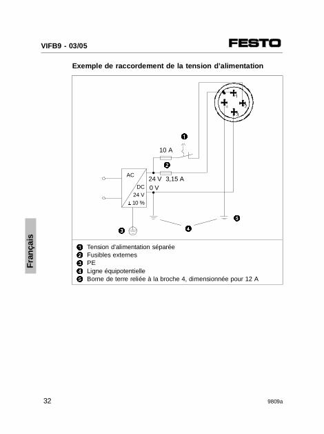
Exemple de raccordement de la tension d’alimentation
1
2
3
4
5
Tension d’alimentation séparéeFusibles externesPELigne équipotentielleBorne de terre reliée à la broche 4, dimensionnée pour 12 A
24 V 3,15 AAC
DC 24 V± 10 %
2
1
0 V
4
5
3
10 A
Fra
nçai
s
VIFB9 - 03/05
32 9809a
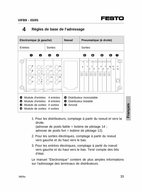
4 Règles de base de l’adressage
Electronique (à gauche) Noeud Pneumatique (à droite)
Entrées Sorties Sorties
1 Module d’entrées 4 entrées2 Module d’entrées 8 entrées3 Module de sorties 4 sorties4 Module de sorties 4 sorties
5 Distributeur monostable6 Distributeur bistable7 Arrondi
1. Pour les distributeurs, comptage à partir du noeud et vers ladroite.(adresse de poids faible = bobine de pilotage 14 ;adresse de poids fort = bobine de pilotage 12).
2. Pour les sorties électriques, comptage à partir du noeudvers gauche et du haut vers le bas.
3. Pour les entrées électriques, comptage à partir du noeudvers gauche et du haut vers le bas. Tenir compte des bitsd’état.
Le manuel "Electronique" contient de plus amples informationssur l’adressage des terminaux de distributeurs.
1 2 3 4 5 6 76 6
Fra
nçai
s
VIFB9 - 03/05
9809a 33
5 Caractéristiques techniques
Type VIFB9-..-
Indice de protection (selon DIN 40050) IP 65 (montage terminé)
Température ambiante - 5o ... + 50 oC
Température de stockage - 20o ... + 60 oC
Broche 1 - du connecteur d’alimentation electronique/entrées
• Tension nom. (protégé contre l’inversion de polarité)
• Tolérance• Courant total max.
DC 24 V
± 25 % (DC 18 V...30 V)2,2 A max.
Broche 2 - du connecteur d’alimentationdistributeurs/sorties
• Tension nom. (protégé contre l’inversion de polarité)
• Tolérance• Courant total max.
DC 24 V
± 10 % (DC 21,6 V...26,4 V)2,2 A max.
Fusible de la tension d’alimentation (entrées/capteurs)
2 A retardé (interne)
Compatibilité électromagnétique
Emission de perturbations• selon la norme EN 55011 Immunité aux perturbations• selon la norme EN 55011
Classe B
Fra
nçai
s
VIFB9 - 03/05
34 9809a
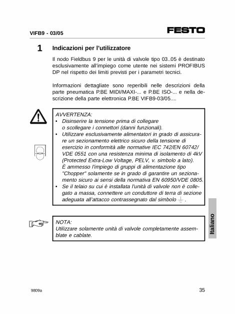
1 Indicazioni per l’utilizzatore
Il nodo Fieldbus 9 per le unità di valvole tipo 03..05 è destinatoesclusivamente all’impiego come utente nei sistemi PROFIBUSDP nel rispetto dei limiti previsti per i parametri tecnici.
Informazioni dettagliate sono reperibili nelle descrizioni dellaparte pneumatica P.BE MIDI/MAXI-... e P.BE ISO-... e nella de-scrizione della parte elettronica P.BE VIFB9-03/05....
AVVERTENZA:• Disinserire la tensione prima di collegare
o scollegare i connettori (danni funzionali).• Utilizzare esclusivamente alimentatori in grado di assicura-
re un sezionamento elettrico sicuro della tensione di esercizio in conformità alle normative IEC 742/EN 60742/VDE 0551 con una resistenza minima di isolamento di 4kV(Protected Extra-Low Voltage, PELV, v. simbolo a lato). È ammesso l’impiego di gruppi di alimentazione tipo "Chopper" solamente se in grado di garantire un seziona-mento sicuro ai sensi della normativa EN 60950/VDE 0805.
• Se il telaio su cui è installata l’unità di valvole non è colle-gato a massa, connettere un conduttore di terra di sezioneadeguata all’attacco contrassegnato dal simbolo .
NOTA:Utilizzare solamente unità di valvole completamente assem-blate e cablate. Ita
liano
VIFB9 - 03/05
9809a 35
2 Configurazione
NOTA:All’apertura del nodo, i cavi di collegamento impediscono dirimuoverne completamente il coperchio.
ATTENZIONE:I componenti dell’unità di valvole contengono elementi elet-tronici sensibili. Toccando le superfici di contatto dei connet-tori a innesto e non rispettando le norme per la manipolazio-ne degli elementi sensibili alle cariche elettrostatiche, si puòprovocare la distruzione dei componenti.
Per la configurazione procedere come segue:1. Disinserire la tensione di esercizio.2. Aprire il nodo (le viti non sono fissate).3. Impostare l’indirizzo Fieldbus.4. Impostare il protocollo.5. Richiudere il nodo.6. Se l’unità di valvole è l’ultimo utente Fieldbus, è necessario
collegare una resistenza terminale.
Baudrate Fieldbus
L’unità di valvole Festo tipo 03/05 si regola automaticamentesul baudrate corretto.
Italia
no
VIFB9 - 03/05
36 9809a
1
2
3
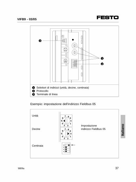
Selettori di indirizzi (unità, decine, centinaia)ProtocolloTerminale di linea
Esempio: impostazione dell’indirizzo Fieldbus 05
Unità
Impostazione
Decine indirizzo Fieldbus 05
Centinaia
AAAAAAAA
AAAAAA
AAAAAA
AAAAAA
1234
AAAA
AAAA
12
1
2
3
12
3
4
65
2
7 8
01
34
9
65
2
7 8
01
34
9
Italia
no
VIFB9 - 03/05
9809a 37
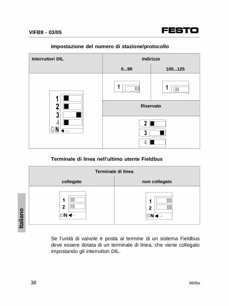
Impostazione del numero di stazione/protocollo
Interruttori DIL Indirizzo
0...99 100...125
Riservato
Terminale di linea nell’ultimo utente Fieldbus
Terminale di linea
collegato non collegato
Se l’unità di valvole è posta al termine di un sistema Fieldbusdeve essere dotata di un terminale di linea, che viene collegatoimpostando gli interruttori DIL.
AAAAAAAAA
AAAAAA AA
AA
AAA
AAAA
AAAA
AAAAAAAAA
AAAAAA
Italia
no
VIFB9 - 03/05
38 9809a
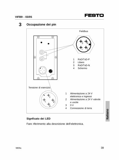
3 Occupazione dei pin
Fieldbus
1 RxD/TxD-P2 Libero3 RxD/TxD-N4 Schermo
Tensione di esercizio
1
2
34
Alimentazione a 24 Velettronica e ingressiAlimentazione a 24 V valvolee uscite0 VConnessione di terra
Signficato dei LED
Fare riferimento alla descrizione dell’elettronica.
Italia
no
VIFB9 - 03/05
9809a 39
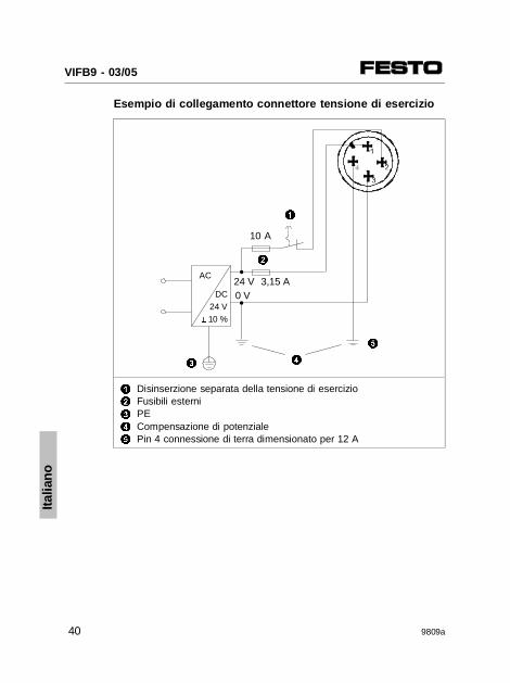
Esempio di collegamento connettore tensione di esercizio
1
2
3
4
5
Disinserzione separata della tensione di esercizioFusibili esterniPECompensazione di potenzialePin 4 connessione di terra dimensionato per 12 A
10 A
24 V 3,15 AAC
DC 24 V± 10 %
2
1
0 V
4
5
3
Italia
no
VIFB9 - 03/05
40 9809a
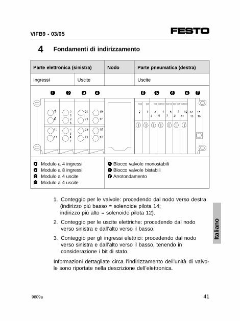
4 Fondamenti di indirizzamento
Parte elettronica (sinistra) Nodo Parte pneumatica (destra)
Ingressi Uscite Uscite
1 Modulo a 4 ingressi2 Modulo a 8 ingressi3 Modulo a 4 uscite4 Modulo a 4 uscite
5 Blocco valvole monostabili6 Blocco valvole bistabili7 Arrotondamento
1. Conteggio per le valvole: procedendo dal nodo verso destra(indirizzo più basso = solenoide pilota 14;indirizzo più alto = solenoide pilota 12).
2. Conteggio per le uscite elettriche: procedendo dal nodo verso sinistra e dall’alto verso il basso.
3. Conteggio per gli ingressi elettrici: procedendo dal nodo verso sinistra e dall’alto verso il basso, tenendo in considerazione i bit di stato.
Informazioni dettagliate circa l’indirizzamento dell’unità di valvo-le sono riportate nella descrizione dell’elettronica.
1 2 3 4 5 6 76 6
Italia
no
VIFB9 - 03/05
9809a 41
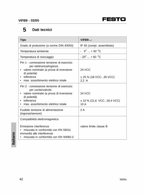
5 Dati tecnici
Tipo VIFB9-..-
Grado di protezione (a norme DIN 40050) IP 65 (compl. assemblato)
Temperatura ambiente - 5o ... + 50 oC
Temperatura di stoccaggio - 20o ... + 60 oC
Pin 1 - connessione tensione di esercizioper elettronica/ingressi
• valore nominale (a prova di inversione di polarità)
• tolleranza• max. assorbimento elettrico totale
24 VCC
± 25 % (18 VCC...30 VCC)2,2 A
Pin 2 - connessione tensione di esercizioper uscite/valvole
• valore nominale (a prova di inversione di polarità)
• tolleranza• max. assorbimento elettrico totale
24 VCC
± 10 % (21,6 VCC...26,4 VCC)10 A
Fusibile tensione di alimentazione (ingressi/sensori)
2 A
Compatibilità elettromagnetica
Emissione interferenze • misurata in conformità con EN 55011Immunità alle interferenze • misurata in conformità con EN 50082-2
valore limite classe B
Italia
no
VIFB9 - 03/05
42 9809a
1 Anvisningar
Fältbussnod 9 för ventilterminalerna 03..05 är avsedd enbart föranvändning som slav på PROFIBUS DP. Därvid ska de angivnagränsvärdena för tekniska data respekteras.
Utförlig information finns i pneumatikmanualerna P.BE MIDI/MAXI-... och P.BE ISO-... samt i elektronikmanualen P.BEVIFB9-03/05....
VARNING:• Koppla från spänningen innan kontakter ansluts
eller dras ur (funktionsskador).• Använd endast nätdelar som garanterar en säker elektrisk
frånkoppling av driftspänningen enligt IEC 742/EN 60742/VDE 0551 med minst 4 kV isolationsmotstånd (Protected Extra-Low Voltage, PELV, se vidstående tecken). Kopplingsnätdelar tillåts om de garanterar en sker frånkoppling enligt EN 60950/VDE 0805.
• Anslut en jordsledning med tillräcklig kabelarea tillden med märkta anslutningen om ventilterminaleninte monterats på ett jordat maskinunderred
ANMÄRKNING:Ta endast en komplett monterad och elektriskt ansluten ven-tilterminal i drift.
Sve
nska
VIFB9 - 03/05
9809a 43
2 Konfiguration
ANMÄRKNING:När noden öppnas, tänk pt att anslutningen för driftspän-ningen har förbindelsekablar till kretskorten i noden. Därförkan locket inte lyftas av helt.
SE UPP:Ventilterminalens komponenter innehåller elektroniskt känsli-ga komponenter. Beröring av kontaktytor på kontakterna ochhantering som strider mot användningsföreskrifterna för elek-trostatiskt känsliga komponenter kan medföra att komponen-terna förstörs.
Gå till väga enligt följande vid konfiguration:1. Koppla från driftspänningen.2. Öppna noden (tappa inte skruvarna).3. Ställ in fältbussadressen.4. Ställ in protokollet.5. Stäng noden.6. Om ventilterminalen är sista fältbusslaven, måste
en terminator aktiveras.
Fältbussöverföringshastighet
Festo ventilterminal 03/05 ställer automatiskt in sig på rätt över-föringshastighet.
Sve
nska
VIFB9 - 03/05
44 9809a
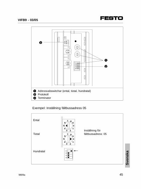
1
2
3
Adressvalsswitchar (ental, tiotal, hundratal)ProtokollTerminator
Exempel: Inställning fältbussadress 05
Ental
Inställning för
Tiotal fältbussadress: 05
Hundratal
AAAAAAAA
AAAAAA
AAAAAA
AAAAAA
1234
AAAA
AAAA
12
1
2
3
12
3
4
65
2
7 8
01
34
9
65
2
7 8
01
34
9
Sve
nska
VIFB9 - 03/05
9809a 45
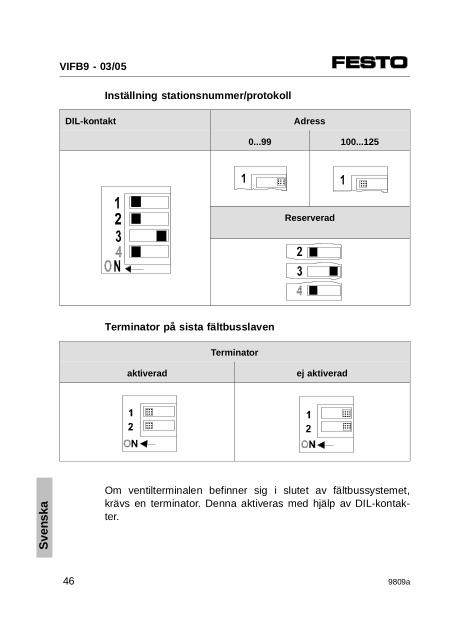
Inställning stationsnummer/protokoll
DIL-kontakt Adress
0...99 100...125
Reserverad
Terminator på sista fältbusslaven
Terminator
aktiverad ej aktiverad
Om ventilterminalen befinner sig i slutet av fältbussystemet,krävs en terminator. Denna aktiveras med hjälp av DIL-kontak-ter.
AAAAAAAAA
AAAAAA AA
AA
AAA
AAAAAA
AAAA
AAAAAA
AAAAAAAAA
Sve
nska
VIFB9 - 03/05
46 9809a
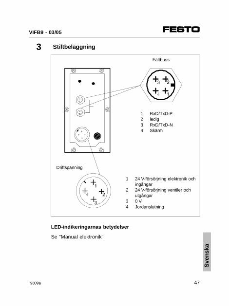
3 Stiftbeläggning
Fältbuss
1 RxD/TxD-P2 ledig3 RxD/TxD-N4 Skärm
Driftspänning
1
2
34
24 V-försörjning elektronik ochingångar24 V-försörjning ventiler ochutgångar0 VJordanslutning
LED-indikeringarnas betydelser
Se "Manual elektronik".
Sve
nska
VIFB9 - 03/05
9809a 47
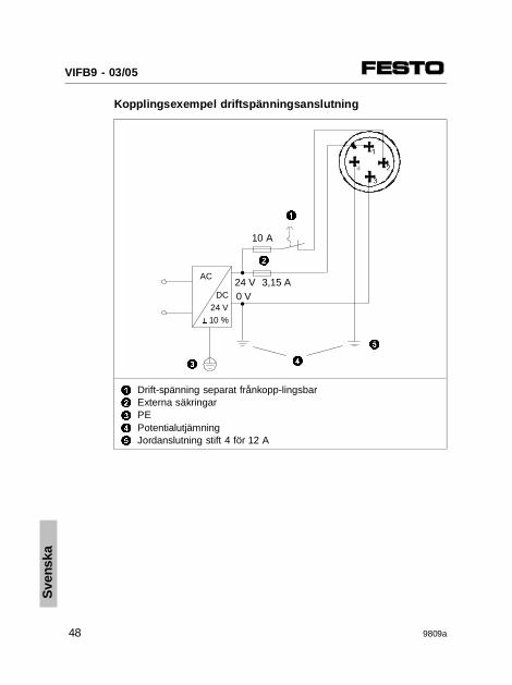
Kopplingsexempel driftspänningsanslutning
1
2
3
4
5
Drift-spänning separat frånkopp-lingsbarExterna säkringarPEPotentialutjämningJordanslutning stift 4 för 12 A
24 V 3,15 AAC
DC 24 V± 10 %
2
1
0 V
4
5
3
10 A
Sve
nska
VIFB9 - 03/05
48 9809a
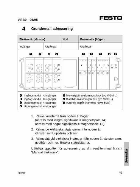
4 Grunderna i adressering
Elektronik (vänster) Nod Pneumatik (höger)
Ingångar Utgångar Utgångar
1 Ingångsmodul 4 ingångar2 Ingångsmodul 8 ingångar3 Utgångsmodul 4 utgångar4 Utgångsmodul 4 utgångar
5 Monostabilt anslutningsblock (typ VIGM-...)6 Bistabilt anslutningsblock (typ VIGI-...)7 Avrunda uppåt (närmsta halva byte)
1. Räkna ventilerna från noden åt höger(adress med längre signifikans = magnetspole 14;adress med högre signifikans = magnetspole 12).
2. Räkna de elektriska utgångarna från noden åtvänster samt uppifrån och ner.
3. Räknesätt vid elektriska ingångar från noden åt vänster samtuppifrån och ner. Beakta statusbitarna.
Utförliga uppgifter för adressering av din ventilterminal finns i"Manual elektronik".
1 2 3 4 5 6 76 6
Sve
nska
VIFB9 - 03/05
9809a 49
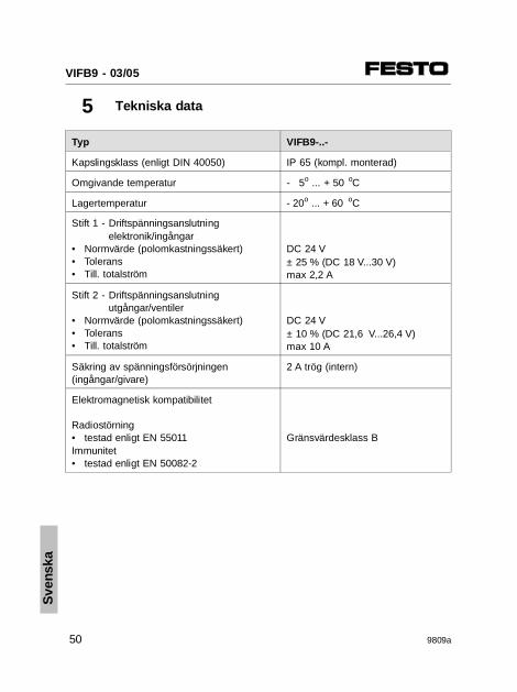
5 Tekniska data
Typ VIFB9-..-
Kapslingsklass (enligt DIN 40050) IP 65 (kompl. monterad)
Omgivande temperatur - 5o ... + 50 oC
Lagertemperatur - 20o ... + 60 oC
Stift 1 - Driftspänningsanslutning elektronik/ingångar
• Normvärde (polomkastningssäkert)• Tolerans• Till. totalström
DC 24 V± 25 % (DC 18 V...30 V)max 2,2 A
Stift 2 - Driftspänningsanslutning utgångar/ventiler
• Normvärde (polomkastningssäkert)• Tolerans• Till. totalström
DC 24 V± 10 % (DC 21,6 V...26,4 V)max 10 A
Säkring av spänningsförsörjningen(ingångar/givare)
2 A trög (intern)
Elektromagnetisk kompatibilitet
Radiostörning• testad enligt EN 55011Immunitet• testad enligt EN 50082-2
Gränsvärdesklass B
Sve
nska
VIFB9 - 03/05
50 9809a