Embed Size (px)
Citation preview
SIMOVERT MASTERDRIVES BetriebsanleitungOperating Instructions
SLS – SIMOLINK Switch
Ausgabe / Edition: AA GWE-477 762 4070.76 J

Weitergabe sowie Vervielfältigung dieser Unterlage, Verwertung undMitteilung ihres Inhalts nicht gestattet, soweit nicht ausdrücklichzugestanden. Zuwiderhandlungen verpflichten zu Schadenersatz.Alle Rechte vorbehalten, insbesondere für den Fall derPatenterteilung oder GM-Eintragung.
Wir haben den Inhalt der Druckschrift auf Übereinstimmung mit derbeschriebenen Hard- und Software überprüft. Dennoch könnenAbweichungen nicht ausgeschlossen werden, so daß wir für dievollständige Übereinstimmung keine Garantie übernehmen. DieAngaben in dieser Druckschrift werden jedoch regelmäßig überprüftund notwendige Korrekturen sind in den nachfolgenden Auflagenenthalten. Für Verbesserungsvorschläge sind wir dankbar SIMOVERT ist ein Warenzeichen von Siemens
The reproduction, transmission or use of this document or its con-tents is not permitted without express written authority. Offenders willbe liable for damages. All rights, including rights created by patentgrant or registration of a utility model or design, are reserved.
We have checked the contents of this document to ensure that theycoincide with the described hardware and software. However,differences cannot be completely excluded, so that we do not acceptany guarantee for complete conformance. However, the informationin this document is regularly checked and necessary corrections willbe included in subsequent editions. We are grateful for anyrecommendations for improvement. SIMOVERT Registered Trade Mark
Siemens AG 2001 All rights reserved
Änderungen von Funktionen, technischen Daten, Normen, Zeichnungen und Parametern vorbehalten.
We reserve the right to make changes to functions, technical data, standards, drawings and parameters.
SIMOLINK Switch 02.2001 Contents
Siemens AG GWE-477 762 4070.76 JSIMOVERT MASTERDRIVES Operating Instructions 1
Contents
1 DEFINITIONS AND WARNINGS......................................................................1-1
2 DESCRIPTION..................................................................................................2-1
2.1 Operating principle ............................................................................................2-1
2.2 Example configuration.......................................................................................2-2
3 TECHNICAL DATA...........................................................................................3-1
4 INSTALLATION ................................................................................................4-1
4.1 EMC measures..................................................................................................4-1
4.2 Housing .............................................................................................................4-1
5 CONNECTIONS................................................................................................5-1
5.1 Connector X1.....................................................................................................5-1
5.2 Fiber-optic cable connections CH1 to CH4 .......................................................5-2
6 START-UP ........................................................................................................6-1
6.1 SIMOLINK Switch mode....................................................................................6-1
6.2 Operating information........................................................................................6-4
6.3 Diagnostics ........................................................................................................6-4

SIMOLINK Switch 02.2001 Definitions and Warnings
Siemens AG GWE-477 762 4070.76 JSIMOVERT MASTERDRIVES Operating Instructions 1-1
1 Definitions and Warnings
For the purpose of this documentation and the product warning labels,a "Qualified person" is someone who is familiar with the installation,mounting, start-up, operation and maintenance of the product. He orshe must have the following qualifications:
♦ Trained or authorized to energize, de-energize, ground and tagcircuits and equipment in accordance with established safetyprocedures.
♦ Trained or authorized in the proper care and use of protectiveequipment in accordance with established safety procedures.
♦ Trained in rendering first aid.
indicates an imminently hazardous situation which, if not avoided, willresult in death, serious injury and considerable damage to property.
indicates a potentially hazardous situation which, if not avoided, couldresult in death, serious injury and considerable damage to property.
used with the safety alert symbol indicates a potentially hazardoussituation which, if not avoided, may result in minor or moderate injury.
used without safety alert symbol indicates a potentially hazardoussituation which, if not avoided, may result in property damage.
NOTICE used without the safety alert symbol indicates a potentialsituation which, if not avoided, may result in an undesirable result orstate.
For the purpose of this documentation, "Note" indicates importantinformation about the product or about the respective part of thedocumentation which is essential to highlight.
Qualified personnel
DANGER
WARNING
CAUTION
CAUTION
NOTICE
NOTE
Definitions and Warnings 02.2001 SIMOLINK Switch
GWE-477 762 4070.76 J Siemens AG1-2 Operating Instructions SIMOVERT MASTERDRIVES
Hazardous voltages are present in this electrical equipment duringoperation.
Non-observance of the warnings can thus result in severe personalinjury or property damage.
Only qualified personnel should work on or around the equipment
This personnel must be thoroughly familiar with all warning andmaintenance procedures contained in this documentation.
The successful and safe operation of this equipment is dependent oncorrect transport, proper storage and installation as well as carefuloperation and maintenance.
This documentation does not purport to cover all details on all types ofthe product, nor to provide for every possible contingency to be met inconnection with installation, operation or maintenance.
Should further information be desired or should particular problemsarise which are not covered sufficiently for the purchaser’s purposes,the matter should be referred to the local SIEMENS sales office.
The contents of this documentation shall not become part of or modifyany prior or existing agreement, commitment or relationship. The salescontract contains the entire obligation of SIEMENS AG. The warrantycontained in the contract between the parties is the sole warranty ofSIEMENS AG. Any statements contained herein do not create newwarranties or modify the existing warranty.
WARNING
NOTE
SIMOLINK Switch 02.2001 Definitions and Warnings
Siemens AG GWE-477 762 4070.76 JSIMOVERT MASTERDRIVES Operating Instructions 1-3
Components which can be destroyed by electrostatic discharge (ESD)
The board contains components which can be destroyed byelectrostatic discharge. These components can be easily destroyed ifnot carefully handled. If you have to handle electronic boards, pleaseobserve the following:
Electronic boards should only be touched when absolutely necessary.
The human body must be electrically discharged before touching anelectronic board.
Boards must not come into contact with highly insulating materials - e.g.plastic parts, insulated desktops, articles of clothing manufactured fromman-made fibers.
Boards must only be placed on conductive surfaces.
Boards and components should only be stored and transported inconductive packaging (e.g. metalized plastic boxes or metalcontainers).
If the packing material is not conductive, the boards must be wrappedwith a conductive packaging material, e.g. conductive foam rubber orhousehold aluminium foil.
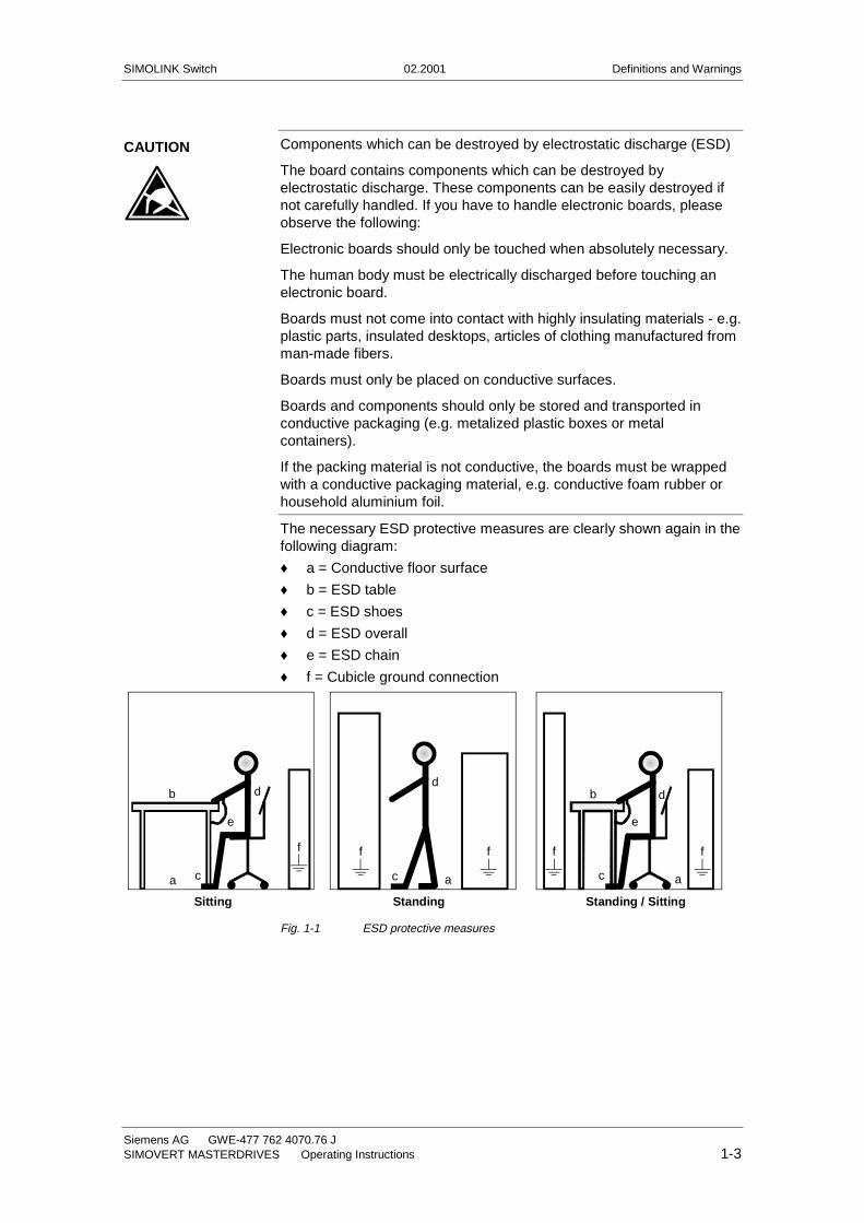
The necessary ESD protective measures are clearly shown again in thefollowing diagram:
♦ a = Conductive floor surface
♦ b = ESD table
♦ c = ESD shoes
♦ d = ESD overall
♦ e = ESD chain
♦ f = Cubicle ground connection
StandingSitting Standing / Sitting
a
b
e
d
c
d
ac
db
c a
e
ff f f f
Fig. 1-1 ESD protective measures
CAUTION

SIMOLINK Switch 02.2001 Description
Siemens AG GWE-477 762 4070.76 JSIMOVERT MASTERDRIVES Operating Instructions 2-1
2 Description
To replace the "line shaft" by a drive system containing several singledrives, these individual drive units must be synchronized with oneanother. This synchronization functionality is provided by SIMOLINK,which also supports distribution of setpoints and internode datacommunication. It may be necessary, for example, when a master fails,to assign its slave drives to another master, or to adjust the topology ofthe SIMOLINK ring to a changing application using a signal "switch".
This is the function of the SIMOLINK Switch (SLS). It allows several (upto 4) SIMOLINK rings to be flexibly interconnected.
The SIMOLINK transmission medium is a fiber-optic cable. Fiber opticsmade of glass or plastic may be used. SIMOLINK has a ring-shapedstructure, with each node in the ring acting as a signal amplifier. Amaximum of 201 active nodes can be interconnected on the SIMOLINKring.
For further information about SIMOLINK, please refer to Chapter"Communication / SIMOLINK“ of the SIMOVERT MASTERDRIVESCompendium Motion Control, Order No.: 6SE7087-6QX50.
2.1 Operating principle
The incoming optical signals carried by the fiber-optic cable areconverted to electrical signals on fiber-optic receiver modules in theSIMOLINK Switch. The control logic determines which input is switchedthrough to which output. One input can only be connected to oneoutput. The electrical output signals of the switching matrix areconverted back to optical signals via fiber-optic transmission modules.The SIMOLINK Switch has 4 ports (channels), each comprising a fiber-optic receiver and transmitter module.
The dead times resulting from the opto-electrical conversion arecalculated as the SIMOLINK system is booting and compensated whenthe SIMOLINK nodes are active. The SIMOLINK Switch is a passivenode in the SIMOLINK ring. It does not have a node address and isexcluded from the dead-time calculation. These factors must be takeninto account as regards the position of the SIMOLINK Switch in theSIMOLINK ring.
The appropriate connections between the input and output signal canbe selected via a DIL switch (local) or binary inputs (remote). Thesettings on the DIL switches have higher priority.
The selected position of the SIMOLINK Switch is displayed by means of5 green LEDs in the front panel. Two LEDs indicate whether theSIMOLINK Switch mode is selected via the DIL switches (Local) or noswitch mode is selected (OFF).
NOTE
Description 02.2001 SIMOLINK Switch
GWE-477 762 4070.76 J Siemens AG2-2 Operating Instructions SIMOVERT MASTERDRIVES
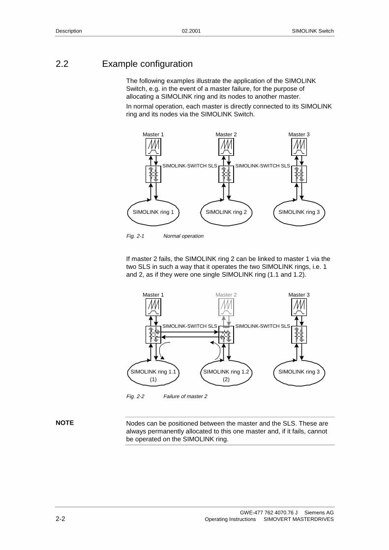
2.2 Example configuration
The following examples illustrate the application of the SIMOLINKSwitch, e.g. in the event of a master failure, for the purpose ofallocating a SIMOLINK ring and its nodes to another master.
In normal operation, each master is directly connected to its SIMOLINKring and its nodes via the SIMOLINK Switch.
Master 1 Master 2 Master 3
SIMOLINK ring 1 SIMOLINK ring 2 SIMOLINK ring 3
SIMOLINK-SWITCH SLSSIMOLINK-SWITCH SLS
Fig. 2-1 Normal operation
If master 2 fails, the SIMOLINK ring 2 can be linked to master 1 via thetwo SLS in such a way that it operates the two SIMOLINK rings, i.e. 1and 2, as if they were one single SIMOLINK ring (1.1 and 1.2).
Master 1 Master 2 Master 3
SIMOLINK ring 1.1(1)
SIMOLINK ring 1.2(2)
SIMOLINK ring 3
SIMOLINK-SWITCH SLSSIMOLINK-SWITCH SLS
Fig. 2-2 Failure of master 2
Nodes can be positioned between the master and the SLS. These arealways permanently allocated to this one master and, if it fails, cannotbe operated on the SIMOLINK ring.
NOTE
SIMOLINK Switch 02.2001 Description
Siemens AG GWE-477 762 4070.76 JSIMOVERT MASTERDRIVES Operating Instructions 2-3
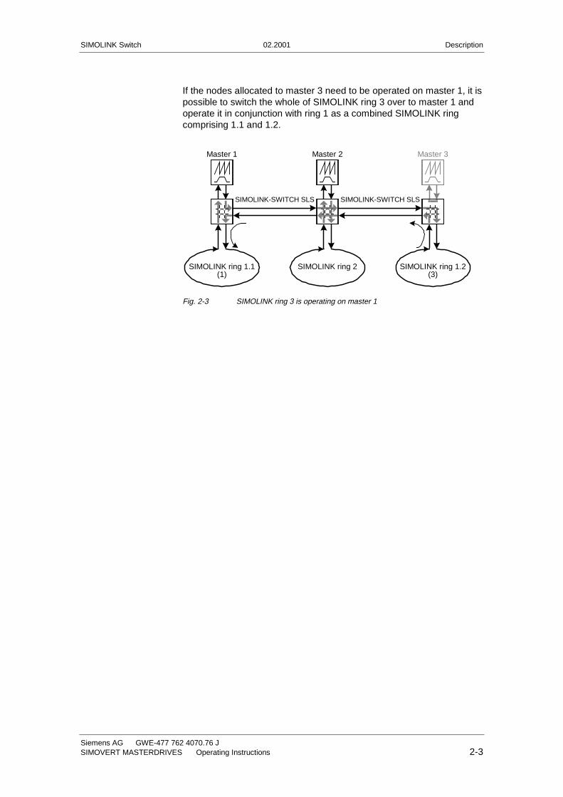
If the nodes allocated to master 3 need to be operated on master 1, it ispossible to switch the whole of SIMOLINK ring 3 over to master 1 andoperate it in conjunction with ring 1 as a combined SIMOLINK ringcomprising 1.1 and 1.2.
Master 1 Master 2 Master 3
SIMOLINK ring 1.1(1)
SIMOLINK ring 2 SIMOLINK ring 1.2(3)
SIMOLINK-SWITCH SLSSIMOLINK-SWITCH SLS
Fig. 2-3 SIMOLINK ring 3 is operating on master 1

SIMOLINK Switch 02.2001 Technical Data
Siemens AG GWE-477 762 4070.76 JSIMOVERT MASTERDRIVES Operating Instructions 3-1
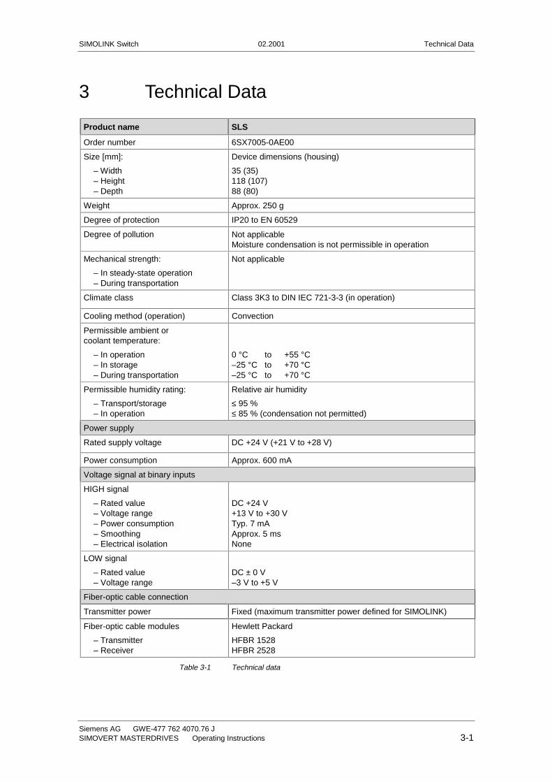
3 Technical Data
Product name SLS
Order number 6SX7005-0AE00
Size [mm]:
– Width– Height– Depth
Device dimensions (housing)
35 (35)118 (107)88 (80)
Weight Approx. 250 g
Degree of protection IP20 to EN 60529
Degree of pollution Not applicableMoisture condensation is not permissible in operation
Mechanical strength:
– In steady-state operation– During transportation
Not applicable
Climate class Class 3K3 to DIN IEC 721-3-3 (in operation)
Cooling method (operation) Convection
Permissible ambient orcoolant temperature:
– In operation– In storage– During transportation
0 °C to +55 °C–25 °C to +70 °C–25 °C to +70 °C
Permissible humidity rating:
– Transport/storage– In operation
Relative air humidity
≤ 95 %≤ 85 % (condensation not permitted)
Power supply
Rated supply voltage DC +24 V (+21 V to +28 V)
Power consumption Approx. 600 mA
Voltage signal at binary inputs
HIGH signal
– Rated value– Voltage range– Power consumption– Smoothing– Electrical isolation
DC +24 V+13 V to +30 VTyp. 7 mAApprox. 5 msNone
LOW signal
– Rated value– Voltage range
DC ± 0 V–3 V to +5 V
Fiber-optic cable connection
Transmitter power Fixed (maximum transmitter power defined for SIMOLINK)
Fiber-optic cable modules
– Transmitter– Receiver
Hewlett Packard
HFBR 1528HFBR 2528
Table 3-1 Technical data

SIMOLINK Switch 02.2001 Installation
Siemens AG GWE-477 762 4070.76 JSIMOVERT MASTERDRIVES Operating Instructions 4-1
4 Installation
The SIMOLINK Switch module is snapped onto an EN 50022-compliantTS 35 top-hat rail. The requisite mechanical mounting elements arefitted in the housing.
4.1 EMC measures
The module is connected to ground via the top-hat rail. The groundconnection between the rail and the equipotential bonding conductormust be made by the end-user during installation.
For further information, please refer to Chapter "Instructions for Designof Drives in Conformance with EMC Regulations" of the SIMOVERTMASTERDRIVES Compendium Motion Control, Order No.:6SE7087-6QX50.
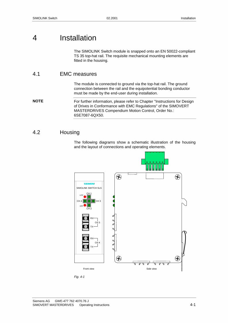
4.2 Housing
The following diagrams show a schematic illustration of the housingand the layout of connections and operating elements.
SIMOLINK SWITCH SLS
CH 1
CH 2
CH 3CH 4
LOC
OFF
RX
TX
RX
TX
CH 3
CH 4
�
Front view Side view
Fig. 4-1
NOTE
Installation 02.2001 SIMOLINK Switch
GWE-477 762 4070.76 J Siemens AG4-2 Operating Instructions SIMOVERT MASTERDRIVES
RX
TX
RX
TX
CH 1
CH 2
OFF ONCH 1
CH 4
CH 2CH 3
CH 1
CH 2
CH 3
CH 4
M
+24 V
View from below Plan view
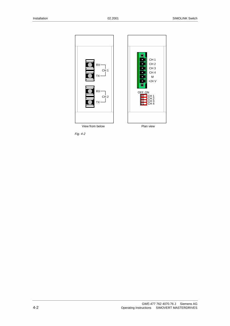
Fig. 4-2
SIMOLINK Switch 02.2001 Connections
Siemens AG GWE-477 762 4070.76 JSIMOVERT MASTERDRIVES Operating Instructions 5-1
5 Connections
The SIMOLINK Switch features
♦ a connector for supplying the module power and mode activation viabinary inputs
♦ four SIMOLINK fiber-optic cable connections, each with one transmitand one receive socket.
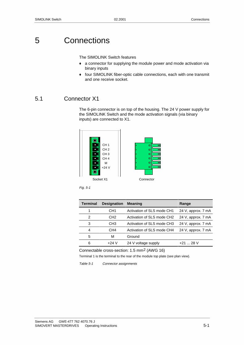
5.1 Connector X1
The 6-pin connector is on top of the housing. The 24 V power supply forthe SIMOLINK Switch and the mode activation signals (via binaryinputs) are connected to X1.
CH 1
CH 2
CH 3
CH 4
M
+24 V
ConnectorSocket X1
Fig. 5-1
Terminal Designation Meaning Range
1 CH1 Activation of SLS mode CH1 24 V, approx. 7 mA
2 CH2 Activation of SLS mode CH2 24 V, approx. 7 mA
3 CH3 Activation of SLS mode CH3 24 V, approx. 7 mA
4 CH4 Activation of SLS mode CH4 24 V, approx. 7 mA
5 M Ground
6 +24 V 24 V voltage supply +21 ... 28 V
Connectable cross-section: 1.5 mm2 (AWG 16)Terminal 1 is the terminal to the rear of the module top plate (see plan view).
Table 5-1 Connector assignments
Connections 02.2001 SIMOLINK Switch
GWE-477 762 4070.76 J Siemens AG5-2 Operating Instructions SIMOVERT MASTERDRIVES
5.2 Fiber-optic cable connections CH1 to CH4
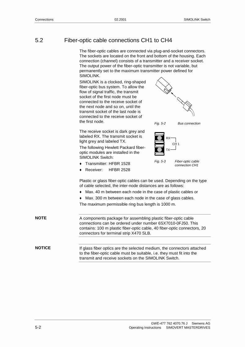
The fiber-optic cables are connected via plug-and-socket connectors.The sockets are located on the front and bottom of the housing. Eachconnection (channel) consists of a transmitter and a receiver socket.The output power of the fiber-optic transmitter is not variable, butpermanently set to the maximum transmitter power defined forSIMOLINK.
SIMOLINK is a clocked, ring-shapedfiber-optic bus system. To allow theflow of signal traffic, the transmitsocket of the first node must beconnected to the receive socket ofthe next node and so on, until thetransmit socket of the last node isconnected to the receive socket ofthe first node.
The receive socket is dark grey andlabeled RX. The transmit socket islight grey and labeled TX.
The following Hewlett Packard fiber-optic modules are installed in theSIMOLINK Switch:
♦ Transmitter: HFBR 1528
♦ Receiver: HFBR 2528
Plastic or glass fiber-optic cables can be used. Depending on the typeof cable selected, the inter-node distances are as follows:
♦ Max. 40 m between each node in the case of plastic cables or
♦ Max. 300 m between each node in the case of glass cables.
The maximum permissible ring bus length is 1000 m.
A components package for assembling plastic fiber-optic cableconnections can be ordered under number 6SX7010-0FJ50. Thiscontains: 100 m plastic fiber-optic cable, 40 fiber-optic connectors, 20connectors for terminal strip X470 SLB.
If glass fiber optics are the selected medium, the connectors attachedto the fiber-optic cable must be suitable, i.e. they must fit into thetransmit and receive sockets on the SIMOLINK Switch.
NOTE
NOTICE
Fig. 5-2 Bus connection
RX
TX
CH 1
Fig. 5-3 Fiber-optic cableconnection CH1
SIMOLINK Switch 02.2001 Connections
Siemens AG GWE-477 762 4070.76 JSIMOVERT MASTERDRIVES Operating Instructions 5-3
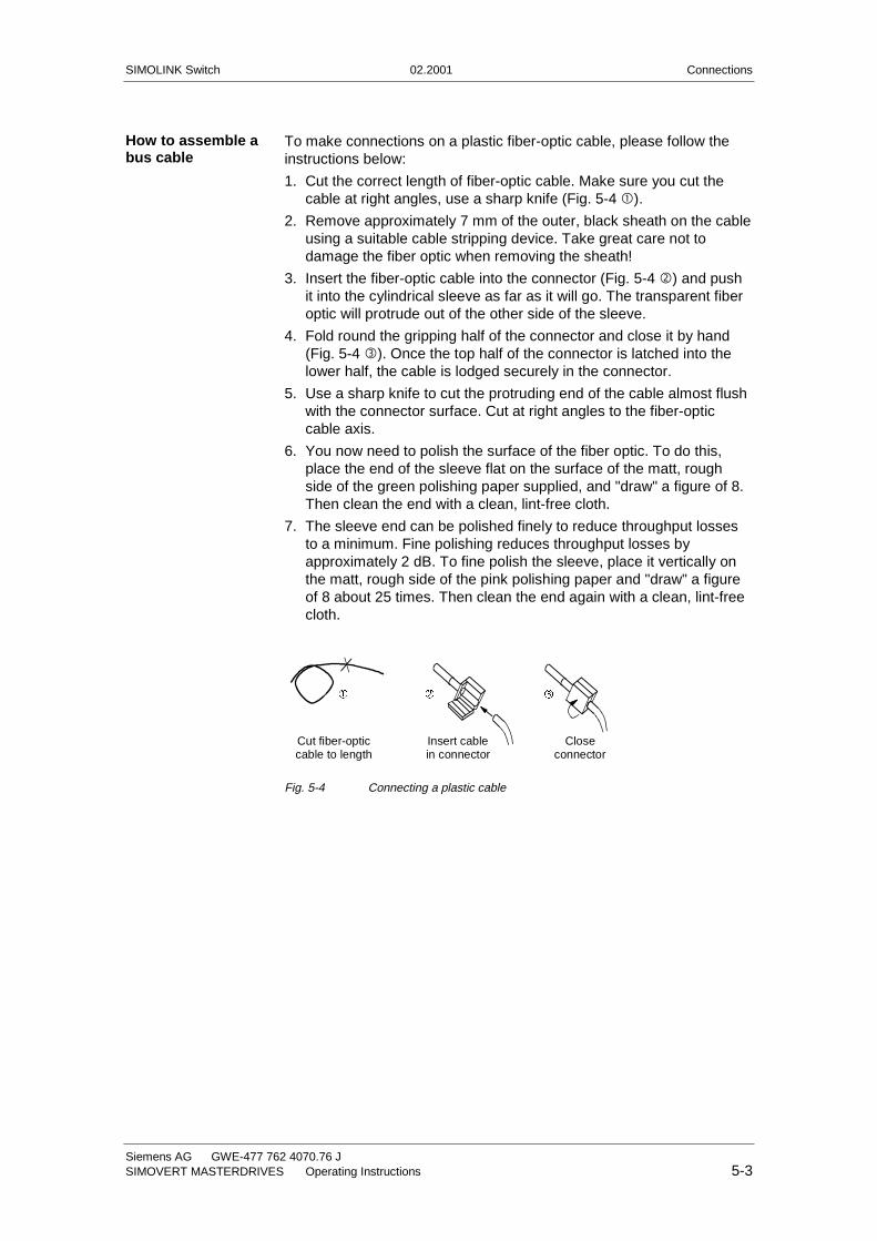
To make connections on a plastic fiber-optic cable, please follow theinstructions below:
1. Cut the correct length of fiber-optic cable. Make sure you cut thecable at right angles, use a sharp knife (Fig. 5-4 �).
2. Remove approximately 7 mm of the outer, black sheath on the cableusing a suitable cable stripping device. Take great care not todamage the fiber optic when removing the sheath!
3. Insert the fiber-optic cable into the connector (Fig. 5-4 ó) and pushit into the cylindrical sleeve as far as it will go. The transparent fiberoptic will protrude out of the other side of the sleeve.
4. Fold round the gripping half of the connector and close it by hand(Fig. 5-4 ì). Once the top half of the connector is latched into thelower half, the cable is lodged securely in the connector.
5. Use a sharp knife to cut the protruding end of the cable almost flushwith the connector surface. Cut at right angles to the fiber-opticcable axis.
6. You now need to polish the surface of the fiber optic. To do this,place the end of the sleeve flat on the surface of the matt, roughside of the green polishing paper supplied, and "draw" a figure of 8.Then clean the end with a clean, lint-free cloth.
7. The sleeve end can be polished finely to reduce throughput lossesto a minimum. Fine polishing reduces throughput losses byapproximately 2 dB. To fine polish the sleeve, place it vertically onthe matt, rough side of the pink polishing paper and "draw" a figureof 8 about 25 times. Then clean the end again with a clean, lint-freecloth.
Cut fiber-opticcable to length
Insert cablein connector
Closeconnector
ì� ó
Fig. 5-4 Connecting a plastic cable
How to assemble abus cable

SIMOLINK Switch 02.2001 Start-Up
Siemens AG GWE-477 762 4070.76 JSIMOVERT MASTERDRIVES Operating Instructions 6-1
6 Start-Up
6.1 SIMOLINK Switch mode
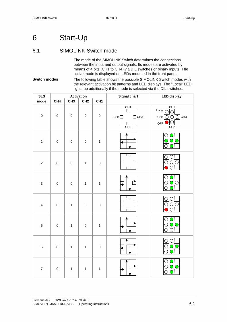
The mode of the SIMOLINK Switch determines the connectionsbetween the input and output signals. Its modes are activated bymeans of 4 bits (CH1 to CH4) via DIL switches or binary inputs. Theactive mode is displayed on LEDs mounted in the front panel.
The following table shows the possible SIMOLINK Switch modes withthe relevant activation bit patterns and LED displays. The "Local" LEDlights up additionally if the mode is selected via the DIL switches.
SLS Activation Signal chart LED displaymode CH4 CH3 CH2 CH1
0 0 0 0 0
CH1
CH2
CH4 CH3
CH1
CH2
CH4 CH3
Local
OFF
1 0 0 0 1
2 0 0 1 0
3 0 0 1 1
4 0 1 0 0
5 0 1 0 1
6 0 1 1 0
7 0 1 1 1
Switch modes
Start-Up 02.2001 SIMOLINK Switch
GWE-477 762 4070.76 J Siemens AG6-2 Operating Instructions SIMOVERT MASTERDRIVES
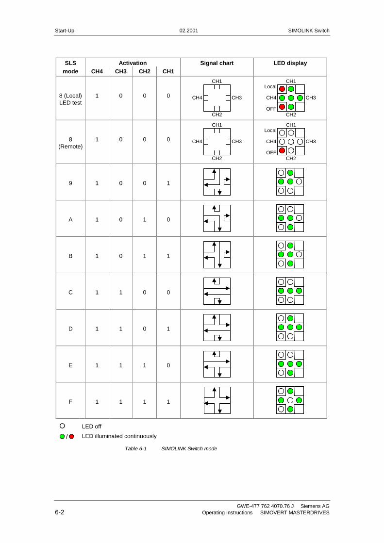
SLS Activation Signal chart LED displaymode CH4 CH3 CH2 CH1
8 (Local)LED test
1 0 0 0
CH1
CH2
CH4 CH3
CH1
CH2
CH4 CH3
Local
OFF
8(Remote)
1 0 0 0
CH1
CH2
CH4 CH3
CH1
CH2
CH4 CH3
Local
OFF
9 1 0 0 1
A 1 0 1 0
B 1 0 1 1
C 1 1 0 0
D 1 1 0 1
E 1 1 1 0
F 1 1 1 1
� LED off
/ LED illuminated continuously
Table 6-1 SIMOLINK Switch mode
SIMOLINK Switch 02.2001 Start-Up
Siemens AG GWE-477 762 4070.76 JSIMOVERT MASTERDRIVES Operating Instructions 6-3
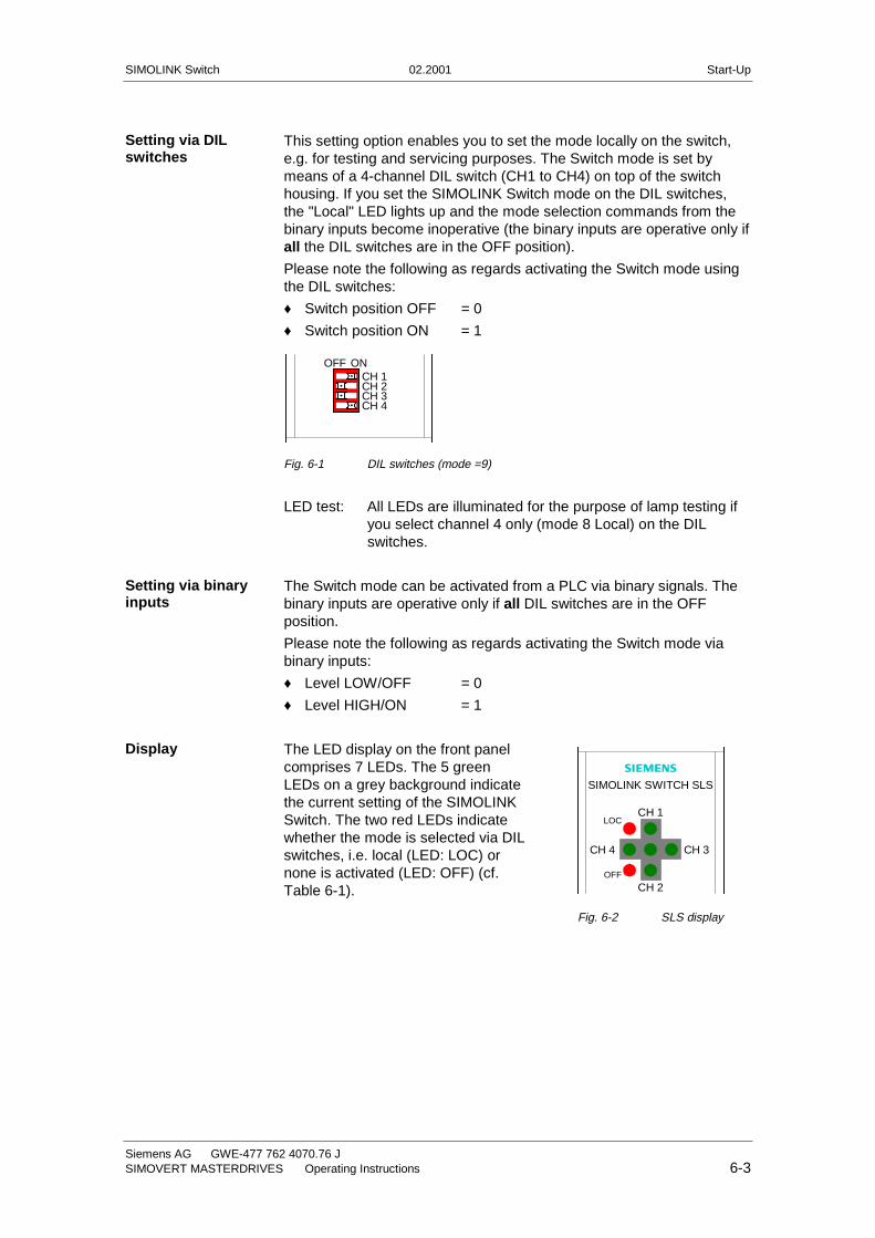
This setting option enables you to set the mode locally on the switch,e.g. for testing and servicing purposes. The Switch mode is set bymeans of a 4-channel DIL switch (CH1 to CH4) on top of the switchhousing. If you set the SIMOLINK Switch mode on the DIL switches,the "Local" LED lights up and the mode selection commands from thebinary inputs become inoperative (the binary inputs are operative only ifall the DIL switches are in the OFF position).
Please note the following as regards activating the Switch mode usingthe DIL switches:
♦ Switch position OFF = 0
♦ Switch position ON = 1
OFF ONCH 1
CH 4
CH 2CH 3
Fig. 6-1 DIL switches (mode =9)
LED test: All LEDs are illuminated for the purpose of lamp testing ifyou select channel 4 only (mode 8 Local) on the DILswitches.
The Switch mode can be activated from a PLC via binary signals. Thebinary inputs are operative only if all DIL switches are in the OFFposition.
Please note the following as regards activating the Switch mode viabinary inputs:
♦ Level LOW/OFF = 0
♦ Level HIGH/ON = 1
The LED display on the front panelcomprises 7 LEDs. The 5 greenLEDs on a grey background indicatethe current setting of the SIMOLINKSwitch. The two red LEDs indicatewhether the mode is selected via DILswitches, i.e. local (LED: LOC) ornone is activated (LED: OFF) (cf.Table 6-1).
Setting via DILswitches
Setting via binaryinputs
Display�
SIMOLINK SWITCH SLS
CH 1
CH 2
CH 3CH 4
LOC
OFF
Fig. 6-2 SLS display
Start-Up 02.2001 SIMOLINK Switch
GWE-477 762 4070.76 J Siemens AG6-4 Operating Instructions SIMOVERT MASTERDRIVES
6.2 Operating information
If the SIMOLINK Switch mode is changed while the switch istransmitting, the incoming signals (converted from optical to electrical)are switched over to the new outputs. This is performed bit by bit,resulting in destruction of the telegram structure. The telegrams arethen transmitted via a new signal route through the modified ringstructure (switchover does not take place at telegram limits). Transmitoperation cannot be interrupted or ended in dispatcher mode. For thisreason, the SLS mode is always changed while the switch istransmitting in dispatcher mode. In order to ensure that all nodes canreliably detect an interruption in transmit operation and the SIMOLINKmaster and dispatcher can execute a proper bus runup, the SIMOLINKSwitch mode must be changed over via OFF mode (mode 0 or 8).
OFF mode must remain selected in dispatcher mode for a periodequaling at least the set telegram failure time of the master before thenew switch mode can be activated. All nodes switch to SIMOLINK errorstatus during runup at the latest and must be acknowledged.
The bus runup operation is required to allow calculation andcompensation of the dead times in SIMOLINK polling caused bypropagation delays. The signal propagation delay is dependent on theSIMOLINK ring topology.
The dead time of a signal throughput (optical to electrical back tooptical from any input to any output) in the SIMOLINK Switch isapproximately 273 ns (3 bit times from 11 Mbit/s transmission speed).
6.3 Diagnostics
Diagnostic LEDs are mounted in the front panel. They indicate thecurrent SIMOLINK Switch mode, whether it has been activated via DILswitches or binary inputs or whether no mode is selected. If onlychannel 4 is selected via the DIL switches, all LEDs light up for lamptesting purposes (Table 6-1).
NOTICE
NOTE
Group: Automation and Drives (A&D)Division: Variable-Speed Drive SystemsPostfach 3269, D-91050 Erlangen
Siemens Aktiengesellschaft Subject to change GWE-477 762 4070.76Printed in the Federal Republic of Germany02.2001
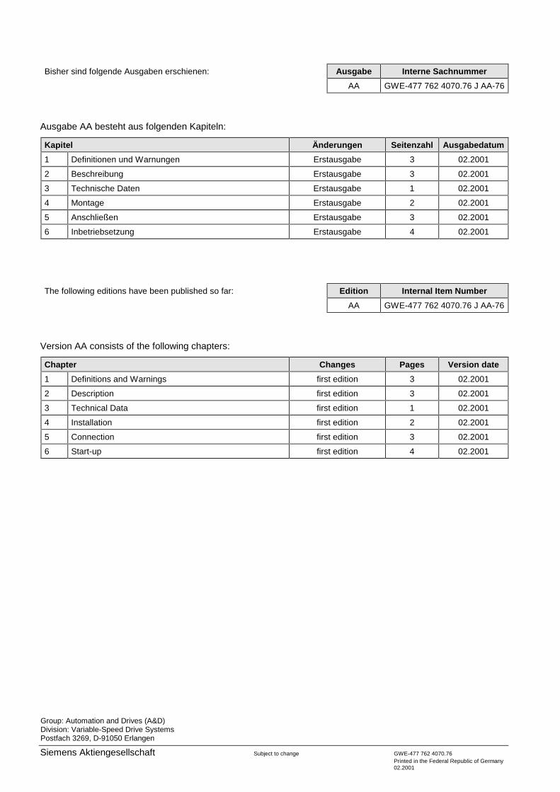
Bisher sind folgende Ausgaben erschienen: Ausgabe Interne Sachnummer
AA GWE-477 762 4070.76 J AA-76
Ausgabe AA besteht aus folgenden Kapiteln:
Kapitel Änderungen Seitenzahl Ausgabedatum
1 Definitionen und Warnungen Erstausgabe 3 02.2001
2 Beschreibung Erstausgabe 3 02.2001
3 Technische Daten Erstausgabe 1 02.2001
4 Montage Erstausgabe 2 02.2001
5 Anschließen Erstausgabe 3 02.2001
6 Inbetriebsetzung Erstausgabe 4 02.2001
The following editions have been published so far: Edition Internal Item Number
AA GWE-477 762 4070.76 J AA-76
Version AA consists of the following chapters:
Chapter Changes Pages Version date
1 Definitions and Warnings first edition 3 02.2001
2 Description first edition 3 02.2001
3 Technical Data first edition 1 02.2001
4 Installation first edition 2 02.2001
5 Connection first edition 3 02.2001
6 Start-up first edition 4 02.2001


![21 의학유전체 검사의뢰서 [Converted] [Converted] · 2017. 10. 19. · Abortus, AF, H.W, QF-21 QF-21, 18, 13 QF-21, 18, 13, XY f 18 f 21 f Cri du chat syn. f DiGeorge 1 (22q11)](https://img.pdfslide.org/doc/110x75/60ac0d45b64b383e4a62786f/21-oe-eeoe-converted-converted-2017-10-19-abortus.jpg)