Embed Size (px)
DESCRIPTION
Sthil trimeri
Citation preview

STIH)
STIHL Series 4180 Powerhead 2005-12
HL 100HT 100HT 101KM 90KM 100KM 110KM 130
FC 90FC 95FC 100FC 110FS 90FS 100FS 110FS 130
www.mymowerparts.com Call 606-678-9623 or 606-561-4983
www.mymowerparts.com Stihl
q© ANDREAS STIHL AG & Co. KG, 2006
Contents
1. Introduction 2
2. Safety Precautions 3
3. Specifications 4
3.1 Engine 43.2 Spark Plug 43.3 Fuel System 43.4 Tightening Torques 5
4. Troubleshooting 7
4.1 Clutch 74.2 Rewind Starter 84.3 Ignition System 94.4 Carburetor 104.5 Engine 12
5. Rewind Starter/Shroud 14
5.1 General 145.2 Removing and
Installing 145.3 Rope Rotor 145.4 Starter Rope 165.4.1 Tensioning 175.5 Pawl 185.6 Replacing the
Rewind Spring 185.7 Removing the Shroud 18
6. Fuel System 19
6.1 Air Filter 196.2 Carburetor 206.2.1 Leakage Test 206.2.2 Removing and
Installing 216.2.3 Manual Fuel Pump 216.2.4 Metering Diaphragm 226.2.5 Inlet Needle 236.2.6 Fixed Jet 236.2.7 Pump Diaphragm 236.3 Accelerator Pump 256.4 Adjusting Idle Speed 256.4.1 Basic Setting 26
Series 4180 Powerhead
6.5 Tank Vent 276.5.1 Checking Operation 276.5.2 Replacing Tank Vent 286.6 Fuel Supply 296.6.1 Cleaning the
Fuel Tank 296.6.2 Fuel Hoses and
Pickup Body 296.6.3 Fuel Tank 31
7. Engine 31
7.1 Compression Pressure 32
7.2 Checking / Adjusting Valve Clearance 32
7.3 Rocker Arms /Pushrods 34
7.4 Cam Followers, Cam Gear 35
7.4.1 Decompression System 36
7.5 Muffler / Spark Arresting Screen 36
7.6 Clutch 377.6.1 Removing and
Disassembling 377.6.2 Assembling and
Installing 387.6.3 Clutch Drum and
Bearing 397.7 Flywheel 407.8 Crankshaft 417.8.1 Replacing the
Oil Seals 417.8.2 Crankcase,
Lower Half 437.8.3 Crankshaft 447.8.4 Piston 457.8.5 Piston Rings 477.9 Valves / Valve Springs 487.10 Upper Half of
Crankcase with Cylinder 49
7.11 Leakage Test 49
8. Ignition System 51
8.1 Spark Plug Boot 518.2 Ignition Module 528.2.1 Ignition Timing 528.2.2 Removing and
Installing 528.3 Testing the
Ignition System 548.4 Ignition System
Troubleshooting 55
9. Throttle Control 58
9.1 Throttle Trigger,Interlock Lever 58
9.2 Tensioner 599.3 Adjusting Throttle
Cable 599.3.1 Control Handle
with Slide 599.3.2 Control Handle
without Slide 609.3.3 Checking Adjustment 619.4 Slide Control 61
10. AV System 62
11. Special Servicing Tools 63
12. Special Accessories 64
1
This service manual contains detailed descriptions of all repair and servicing procedures specific to this powerhead.
You should make use of the illustrated parts lists while carrying out repair work. They show the installed positions of the individual components and assemblies.
Refer to the latest edition of the relevant parts list to check the part numbers of any replacement parts.
Refer to the “Technical Information” bulletins for engineering changes which have been introduced since publication of this service manual. Technical information bulletins also supplement the parts list until a
revised edition is issued.The special servicing tools mentioned in the descriptions are listed in the last chapter of this manual. Use the part numbers to identify the tools in the "STIHL Special Tools” manual.
2
Symbols are included in the text and pictures for greater clarity.The meanings are as follows:
In the descriptions:
: = Action to be taken as shown in the illustration (above the text)
– = Action to be taken that is not shown in the illustration (above the text)
b 4.2 = Reference to another chapter, i.e. chapter 4.2 in this example
+= Situation applies fromserial No.
*= Situation applies up toserial No.
In the illustrations:
A Pointer
aDirection of movement
Service manuals and technical information bulletins are intended exclusively for the use of properly equipped repair shops. They must not be passed to third parties.
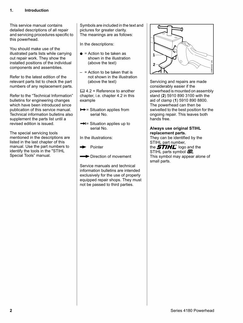
Servicing and repairs are made considerably easier if the powerhead is mounted on assembly stand (2) 5910 890 3100 with the aid of clamp (1) 5910 890 8800.The powerhead can then be swivelled to the best position for the ongoing repair. This leaves both
VA
249R
A!6
32
1
hands free.
Always use original STIHL replacement parts.They can be identified by theSTIHL part number,the STIH) logo and the STIHL parts symbol (This symbol may appear alone of small parts.
1. Introduction
Series 4180 Powerhead
If the engine is started up in the course of repairs or maintenance work, observe all local and country-specific safety regulations as well as the safety precautions and warnings in the instruction manual.
Gasoline is an extremely flammable fuel and can be explosive in certain conditions.
Improper handling may result in burns or other serious injuries.
If parts are heated during servicing work, always wear suitable protective gloves.
Do not bring any fire, flame, spark or other source of heat near the fuel. All work with fuel must be performed
outdoors only. Spilled fuel must be wiped away immediately.Check for leaks after performing any work on the fuel system or engine.
Series 4180 Powerhead
2. Safety Precautions
3
3. Specifications
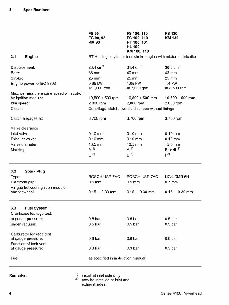
Remarks: 1) install at inlet side only2) may be installed at inlet and
exhaust sides
FS 90FC 90, 95KM 90
FS 100, 110FC 100, 110HT 100, 101HL 100KM 100, 110
FS 130KM 130
3.1 Engine STIHL single cylinder four-stroke engine with mixture lubrication
Displacement: 28.4 cm3 31.4 cm3 36.3 cm3
Bore: 38 mm 40 mm 43 mmStroke: 25 mm 25 mm 25 mmEngine power to ISO 8893 0.95 kW
at 7,000 rpm1.05 kWat 7,000 rpm
1.4 kWat 8,500 rpm
Max. permissible engine speed with cut-off by ignition module: 10,500 ± 500 rpm 10,500 ± 500 rpm 10,500 ± 500 rpmIdle speed: 2,800 rpm 2,800 rpm 2,800 rpmClutch: Centrifugal clutch, two clutch shoes without linings
Clutch engages at: 3,700 rpm 3,700 rpm 3,700 rpm
Valve clearanceInlet valve: 0.10 mm 0.10 mm 0.10 mmExhaust valve: 0.10 mm 0.10 mm 0.10 mmValve diameter: 13.5 mm 13.5 mm 15.5 mmMarking: A 1) A 1) B or : 1)
E 2) E 2) I 2)
3.2 Spark PlugType: BOSCH USR 7AC BOSCH USR 7AC NGK CMR 6HElectrode gap: 0.5 mm 0.5 mm 0.7 mmAir gap between ignition module and fanwheel: 0.15 ... 0.30 mm 0.15 ... 0.30 mm 0.15 ... 0.30 mm
3.3 Fuel SystemCrankcase leakage test:at gauge pressure: 0.5 bar 0.5 bar 0.5 barunder vacuum: 0.5 bar 0.5 bar 0.5 bar
Carburetor leakage test at gauge pressure: 0.8 bar 0.8 bar 0.8 barFunction of tank ventat gauge pressure: 0.3 bar 0.3 bar 0.3 bar
Fuel: as specified in instruction manual
4 Series 4180 Powerhead
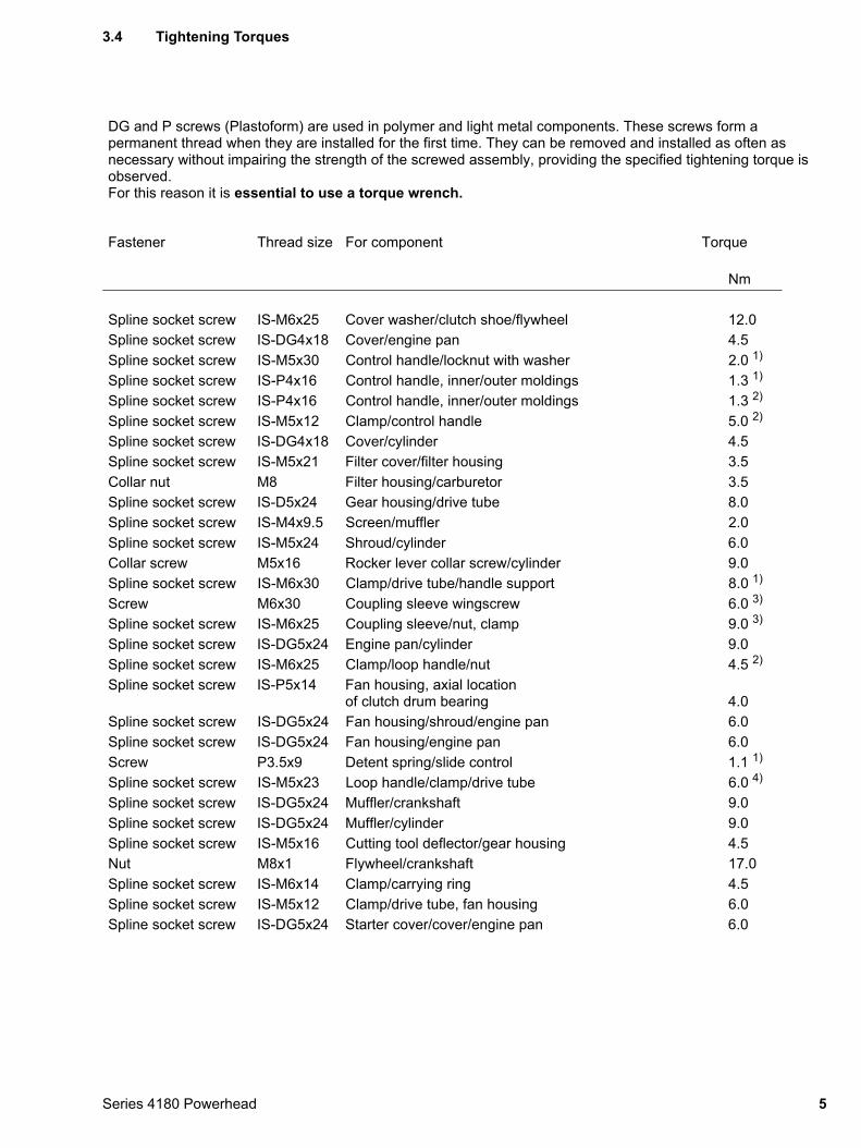
3.4 Tightening Torques
DG and P screws (Plastoform) are used in polymer and light metal components. These screws form a permanent thread when they are installed for the first time. They can be removed and installed as often as necessary without impairing the strength of the screwed assembly, providing the specified tightening torque is observed.For this reason it is essential to use a torque wrench.
Fastener Thread size For component Torque
Nm
Spline socket screw IS-M6x25 Cover washer/clutch shoe/flywheel 12.0Spline socket screw IS-DG4x18 Cover/engine pan 4.5Spline socket screw IS-M5x30 Control handle/locknut with washer 2.0 1)
Spline socket screw IS-P4x16 Control handle, inner/outer moldings 1.3 1)
Spline socket screw IS-P4x16 Control handle, inner/outer moldings 1.3 2)
Spline socket screw IS-M5x12 Clamp/control handle 5.0 2)
Spline socket screw IS-DG4x18 Cover/cylinder 4.5Spline socket screw IS-M5x21 Filter cover/filter housing 3.5Collar nut M8 Filter housing/carburetor 3.5Spline socket screw IS-D5x24 Gear housing/drive tube 8.0Spline socket screw IS-M4x9.5 Screen/muffler 2.0Spline socket screw IS-M5x24 Shroud/cylinder 6.0Collar screw M5x16 Rocker lever collar screw/cylinder 9.0Spline socket screw IS-M6x30 Clamp/drive tube/handle support 8.0 1)
Screw M6x30 Coupling sleeve wingscrew 6.0 3)
Spline socket screw IS-M6x25 Coupling sleeve/nut, clamp 9.0 3)
Spline socket screw IS-DG5x24 Engine pan/cylinder 9.0Spline socket screw IS-M6x25 Clamp/loop handle/nut 4.5 2)
Spline socket screw IS-P5x14 Fan housing, axial location of clutch drum bearing 4.0
Spline socket screw IS-DG5x24 Fan housing/shroud/engine pan 6.0Spline socket screw IS-DG5x24 Fan housing/engine pan 6.0Screw P3.5x9 Detent spring/slide control 1.1 1)
Spline socket screw IS-M5x23 Loop handle/clamp/drive tube 6.0 4)
Spline socket screw IS-DG5x24 Muffler/crankshaft 9.0Spline socket screw IS-DG5x24 Muffler/cylinder 9.0Spline socket screw IS-M5x16 Cutting tool deflector/gear housing 4.5Nut M8x1 Flywheel/crankshaft 17.0Spline socket screw IS-M6x14 Clamp/carrying ring 4.5Spline socket screw IS-M5x12 Clamp/drive tube, fan housing 6.0Spline socket screw IS-DG5x24 Starter cover/cover/engine pan 6.0
5Series 4180 Powerhead
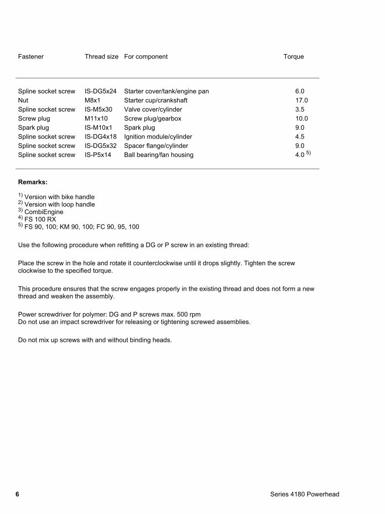
Fastener Thread size For component Torque
Spline socket screw IS-DG5x24 Starter cover/tank/engine pan 6.0Nut M8x1 Starter cup/crankshaft 17.0Spline socket screw IS-M5x30 Valve cover/cylinder 3.5Screw plug M11x10 Screw plug/gearbox 10.0Spark plug IS-M10x1 Spark plug 9.0Spline socket screw IS-DG4x18 Ignition module/cylinder 4.5Spline socket screw IS-DG5x32 Spacer flange/cylinder 9.0Spline socket screw IS-P5x14 Ball bearing/fan housing 4.0 5)
Remarks:
1) Version with bike handle2) Version with loop handle3) CombiEngine4) FS 100 RX5) FS 90, 100; KM 90, 100; FC 90, 95, 100
Use the following procedure when refitting a DG or P screw in an existing thread:
Place the screw in the hole and rotate it counterclockwise until it drops slightly. Tighten the screw clockwise to the specified torque.
This procedure ensures that the screw engages properly in the existing thread and does not form a new thread and weaken the assembly.
Power screwdriver for polymer: DG and P screws max. 500 rpmDo not use an impact screwdriver for releasing or tightening screwed assemblies.
Do not mix up screws with and without binding heads.
6 Series 4180 Powerhead
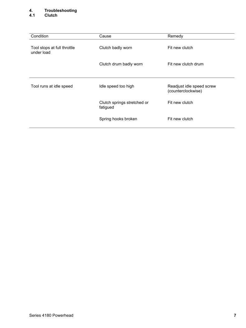
4. Troubleshooting4.1 Clutch
Condition Cause Remedy
Tool stops at full throttle under load
Clutch badly worn Fit new clutch
Clutch drum badly worn Fit new clutch drum
Tool runs at idle speed Idle speed too high Readjust idle speed screw (counterclockwise)
Clutch springs stretched or fatigued
Fit new clutch
Spring hooks broken Fit new clutch
7Series 4180 Powerhead
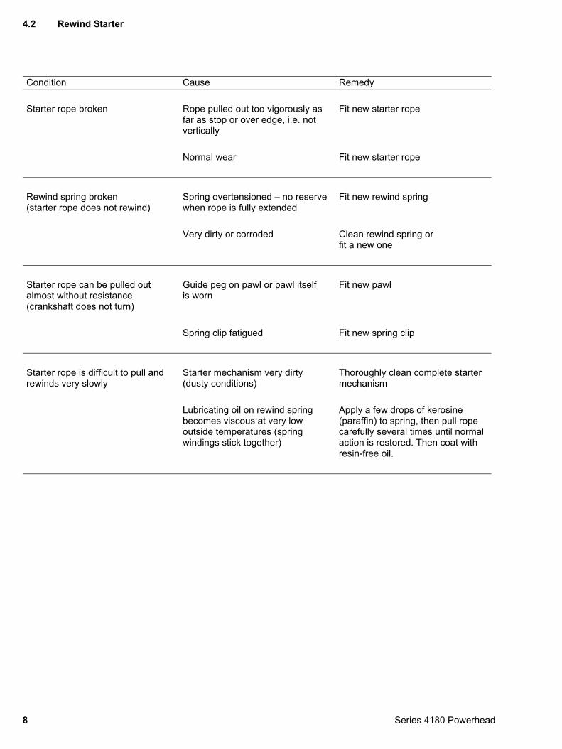
4.2 Rewind Starter
Condition Cause Remedy
Starter rope broken Rope pulled out too vigorously as far as stop or over edge, i.e. not vertically
Fit new starter rope
Normal wear Fit new starter rope
Rewind spring broken (starter rope does not rewind)
Spring overtensioned – no reserve when rope is fully extended
Fit new rewind spring
Very dirty or corroded Clean rewind spring orfit a new one
Starter rope can be pulled out almost without resistance (crankshaft does not turn)
Guide peg on pawl or pawl itself is worn
Fit new pawl
Spring clip fatigued Fit new spring clip
Starter rope is difficult to pull and rewinds very slowly
Starter mechanism very dirty (dusty conditions)
Thoroughly clean complete starter mechanism
Lubricating oil on rewind spring becomes viscous at very low outside temperatures (spring windings stick together)
Apply a few drops of kerosine (paraffin) to spring, then pull rope carefully several times until normal action is restored. Then coat with resin-free oil.
8 Series 4180 Powerhead
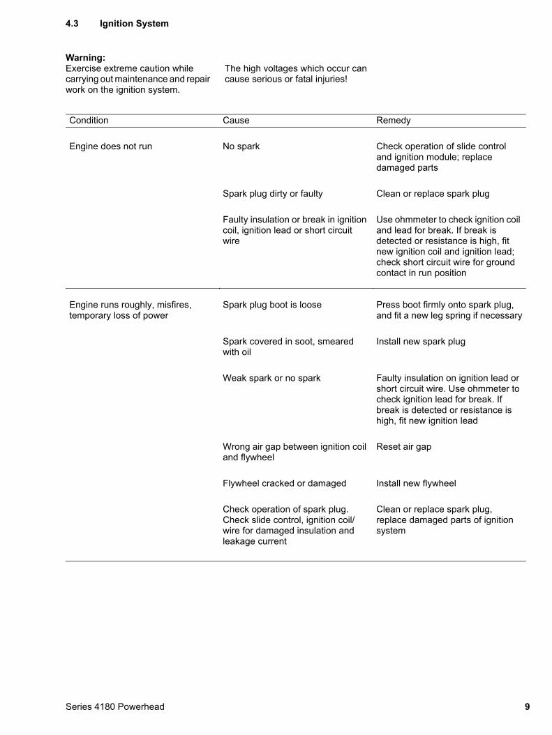
4.3 Ignition System
Warning:
Exercise extreme caution while carrying out maintenance and repair work on the ignition system.The high voltages which occur can cause serious or fatal injuries!
Condition Cause Remedy
Engine does not run No spark Check operation of slide control and ignition module; replace damaged parts
Spark plug dirty or faulty Clean or replace spark plug
Faulty insulation or break in ignition coil, ignition lead or short circuit wire
Use ohmmeter to check ignition coil and lead for break. If break is detected or resistance is high, fit new ignition coil and ignition lead; check short circuit wire for ground contact in run position
Engine runs roughly, misfires, temporary loss of power
Spark plug boot is loose Press boot firmly onto spark plug, and fit a new leg spring if necessary
Spark covered in soot, smeared with oil
Install new spark plug
Weak spark or no spark Faulty insulation on ignition lead or short circuit wire. Use ohmmeter to check ignition lead for break. If break is detected or resistance is high, fit new ignition lead
Wrong air gap between ignition coil and flywheel
Reset air gap
Flywheel cracked or damaged Install new flywheel
Check operation of spark plug. Check slide control, ignition coil/wire for damaged insulation and leakage current
Clean or replace spark plug, replace damaged parts of ignition system
9Series 4180 Powerhead
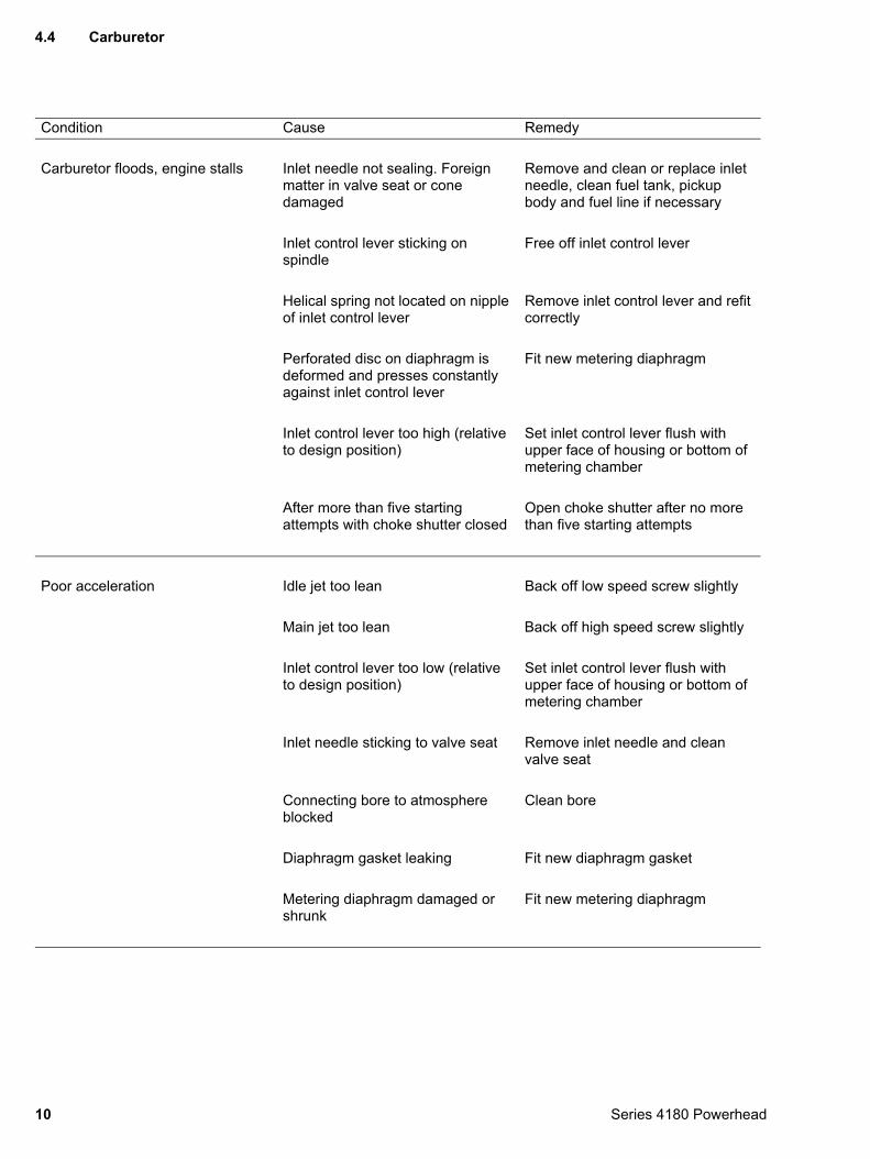
4.4 Carburetor
Condition Cause Remedy
Carburetor floods, engine stalls Inlet needle not sealing. Foreign matter in valve seat or cone damaged
Remove and clean or replace inlet needle, clean fuel tank, pickup body and fuel line if necessary
Inlet control lever sticking on spindle
Free off inlet control lever
Helical spring not located on nipple of inlet control lever
Remove inlet control lever and refit correctly
Perforated disc on diaphragm is deformed and presses constantly against inlet control lever
Fit new metering diaphragm
Inlet control lever too high (relative to design position)
Set inlet control lever flush with upper face of housing or bottom of metering chamber
After more than five starting attempts with choke shutter closed
Open choke shutter after no more than five starting attempts
Poor acceleration Idle jet too lean Back off low speed screw slightly
Main jet too lean Back off high speed screw slightly
Inlet control lever too low (relative to design position)
Set inlet control lever flush with upper face of housing or bottom of metering chamber
Inlet needle sticking to valve seat Remove inlet needle and clean valve seat
Connecting bore to atmosphere blocked
Clean bore
Diaphragm gasket leaking Fit new diaphragm gasket
Metering diaphragm damaged or shrunk
Fit new metering diaphragm
10 Series 4180 Powerhead
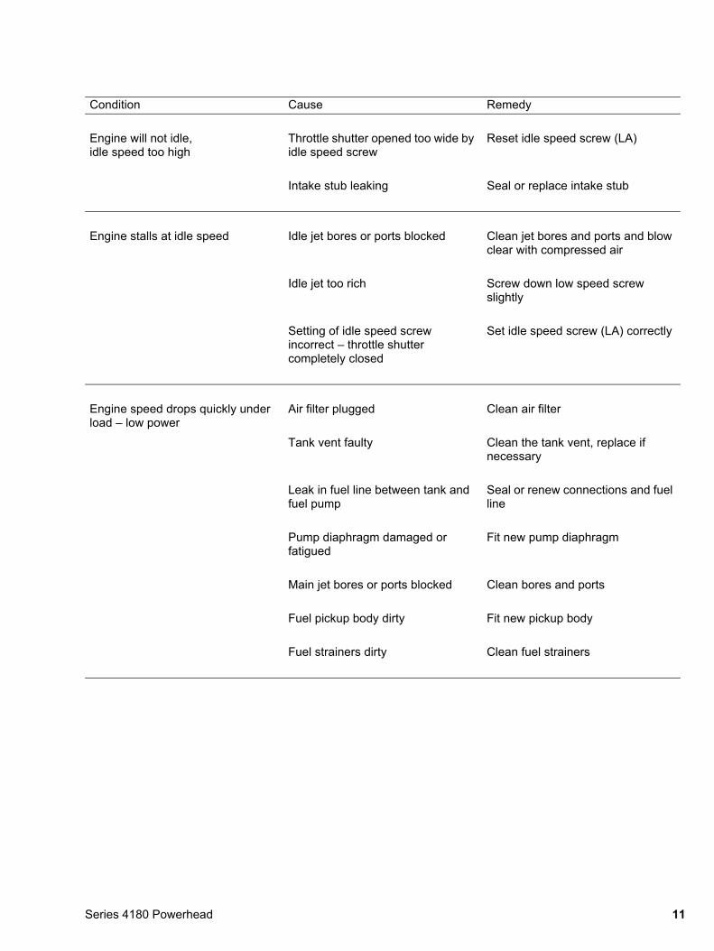
Condition Cause Remedy
Engine will not idle, idle speed too high
Throttle shutter opened too wide by idle speed screw
Reset idle speed screw (LA)
Intake stub leaking Seal or replace intake stub
Engine stalls at idle speed Idle jet bores or ports blocked Clean jet bores and ports and blow clear with compressed air
Idle jet too rich Screw down low speed screw slightly
Setting of idle speed screw incorrect – throttle shutter completely closed
Set idle speed screw (LA) correctly
Engine speed drops quickly under load – low power
Air filter plugged Clean air filter
Tank vent faulty Clean the tank vent, replace if necessary
Leak in fuel line between tank and fuel pump
Seal or renew connections and fuel line
Pump diaphragm damaged or fatigued
Fit new pump diaphragm
Main jet bores or ports blocked Clean bores and ports
Fuel pickup body dirty Fit new pickup body
Fuel strainers dirty Clean fuel strainers
11Series 4180 Powerhead
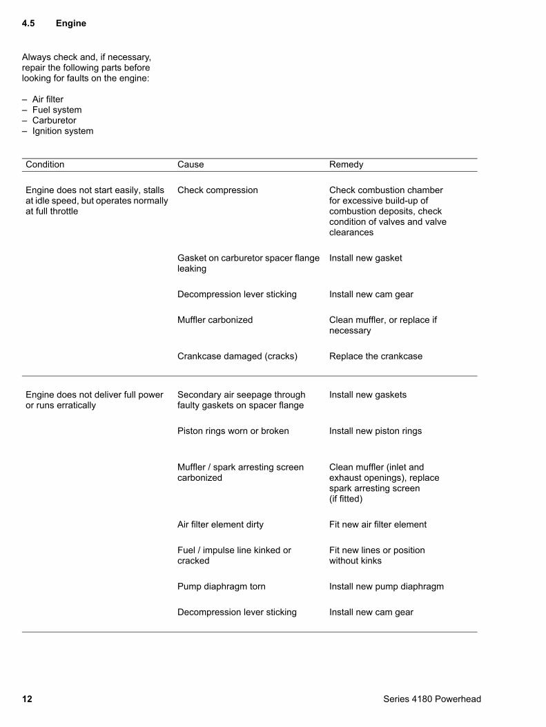
4.5 Engine
Always check and, if necessary,
repair the following parts before looking for faults on the engine:– Air filter– Fuel system– Carburetor– Ignition system
Condition Cause Remedy
Engine does not start easily, stalls at idle speed, but operates normally at full throttle
Check compression Check combustion chamber for excessive build-up of combustion deposits, check condition of valves and valve clearances
Gasket on carburetor spacer flange leaking
Install new gasket
Decompression lever sticking Install new cam gear
Muffler carbonized Clean muffler, or replace if necessary
Crankcase damaged (cracks) Replace the crankcase
Engine does not deliver full power or runs erratically
Secondary air seepage through faulty gaskets on spacer flange
Install new gaskets
Piston rings worn or broken Install new piston rings
Muffler / spark arresting screen carbonized
Clean muffler (inlet and exhaust openings), replace spark arresting screen (if fitted)
Air filter element dirty Fit new air filter element
Fuel / impulse line kinked or cracked
Fit new lines or position without kinks
Pump diaphragm torn Install new pump diaphragm
Decompression lever sticking Install new cam gear
12 Series 4180 Powerhead

Condition Cause Remedy
Engine overheating Insufficient cylinder cooling.Air inlets in fan housing blocked or cooling fins on cylinder very dirty
Thoroughly clean all cooling air passages and cooling fins
13Series 4180 Powerhead
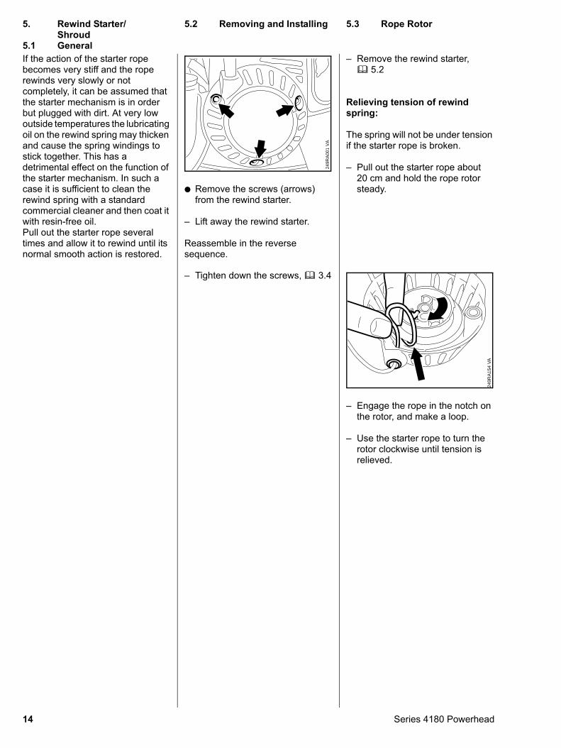
If the action of the starter rope becomes very stiff and the rope rewinds very slowly or not completely, it can be assumed that the starter mechanism is in order but plugged with dirt. At very low outside temperatures the lubricating oil on the rewind spring may thicken and cause the spring windings to stick together. This has a detrimental effect on the function of the starter mechanism. In such a case it is sufficient to clean the rewind spring with a standard commercial cleaner and then coat it with resin-free oil. Pull out the starter rope several times and allow it to rewind until its normal smooth action is restored.
5.1 General
14
: Remove the screws (arrows) from the rewind starter.
– Lift away the rewind starter.
Reassemble in the reverse sequence.
VA
249R
A00
1
– Tighten down the screws, b 3.4
– Remove the rewind starter, b 5.2
Relieving tension of rewind spring:
The spring will not be under tension if the starter rope is broken.
– Pull out the starter rope about 20 cm and hold the rope rotor steady.
– Engage the rope in the notch on the rotor, and make a loop.
– Use the starter rope to turn the rotor clockwise until tension is relieved.
VA
249R
A15
4
5. Rewind Starter/Shroud
5.2 Removing and Installing
5.3 Rope RotorSeries 4180 Powerhead
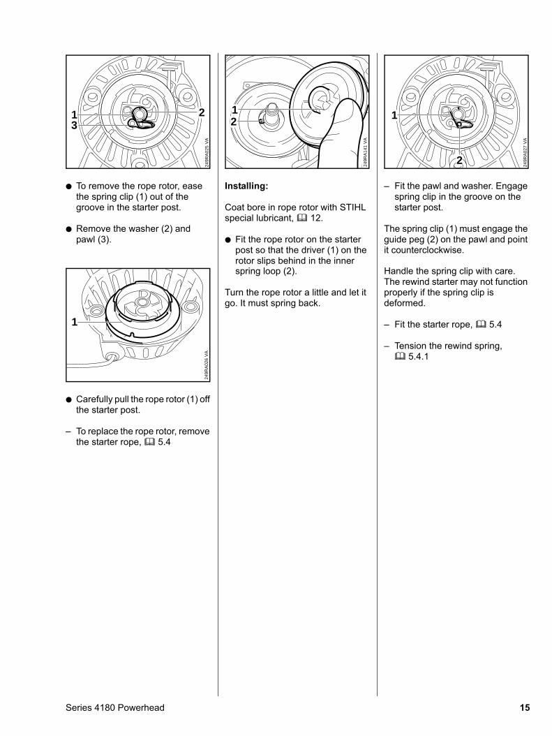
: To remove the rope rotor, ease the spring clip (1) out of the groove in the starter post.
: Remove the washer (2) and pawl (3).
VA
249R
A02
5
31 2
: Carefully pull the rope rotor (1) off the starter post.
– To replace the rope rotor, remove the starter rope, b 5.4
1
VA
249R
A02
6
Series 4180 Powerhead
Installing:
Coat bore in rope rotor with STIHL special lubricant, b 12.
: Fit the rope rotor on the starter post so that the driver (1) on the rotor slips behind in the inner
VA
249R
A14
1
12
spring loop (2).
Turn the rope rotor a little and let it go. It must spring back.
– Fit the pawl and washer. Engage spring clip in the groove on the starter post.
The spring clip (1) must engage the guide peg (2) on the pawl and point it counterclockwise.
VA
249R
A02
7
2
1
Handle the spring clip with care.
The rewind starter may not function properly if the spring clip is deformed.– Fit the starter rope, b 5.4
– Tension the rewind spring, b 5.4.1
15
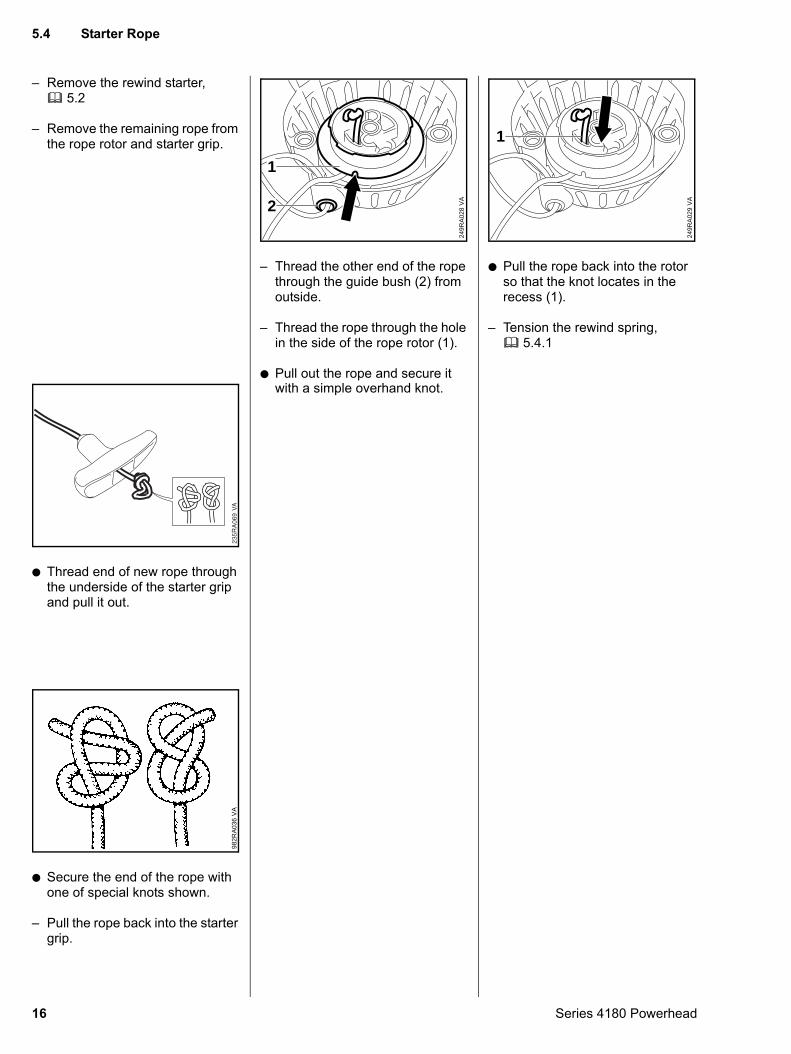
– Remove the rewind starter, b 5.2
– Remove the remaining rope from the rope rotor and starter grip.
: Thread end of new rope through the underside of the starter grip and pull it out.
: Secure the end of the rope with one of special knots shown.
– Pull the rope back into the starter grip.
VA
982R
A03
6
16
– Thread the other end of the rope through the guide bush (2) from outside.
– Thread the rope through the hole in the side of the rope rotor (1).
: Pull out the rope and secure it
VA
249R
A02
8
1
2
with a simple overhand knot.
: Pull the rope back into the rotor so that the knot locates in the recess (1).
– Tension the rewind spring, b 5.4.1
1
VA
249R
A02
9
5.4 Starter Rope
Series 4180 Powerhead
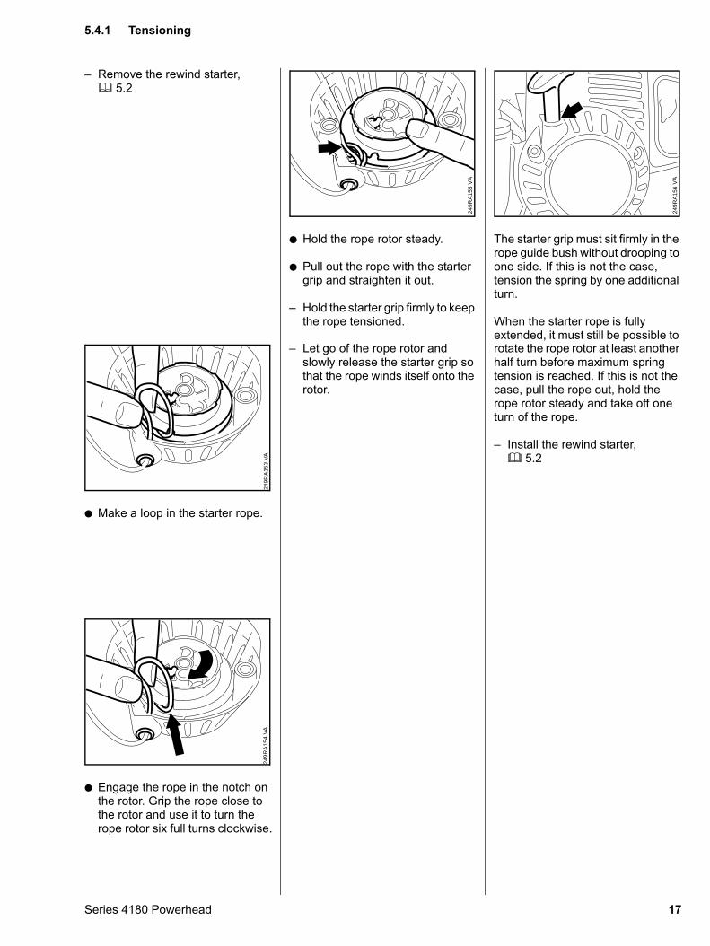
– Remove the rewind starter, b 5.2
: Make a loop in the starter rope.
VA
249R
A15
3
: Engage the rope in the notch on the rotor. Grip the rope close to the rotor and use it to turn the rope rotor six full turns clockwise.
VA
249R
A15
4
Series 4180 Powerhead
: Hold the rope rotor steady.
: Pull out the rope with the starter grip and straighten it out.
– Hold the starter grip firmly to keep the rope tensioned.
VA
249R
A15
5
– Let go of the rope rotor and
slowly release the starter grip so that the rope winds itself onto the rotor.The starter grip must sit firmly in the rope guide bush without drooping to one side. If this is not the case, tension the spring by one additional turn.
When the starter rope is fully extended, it must still be possible to
VA
249R
A15
6
rotate the rope rotor at least another
half turn before maximum spring tension is reached. If this is not the case, pull the rope out, hold the rope rotor steady and take off one turn of the rope.– Install the rewind starter, b 5.2
5.4.1 Tensioning
17
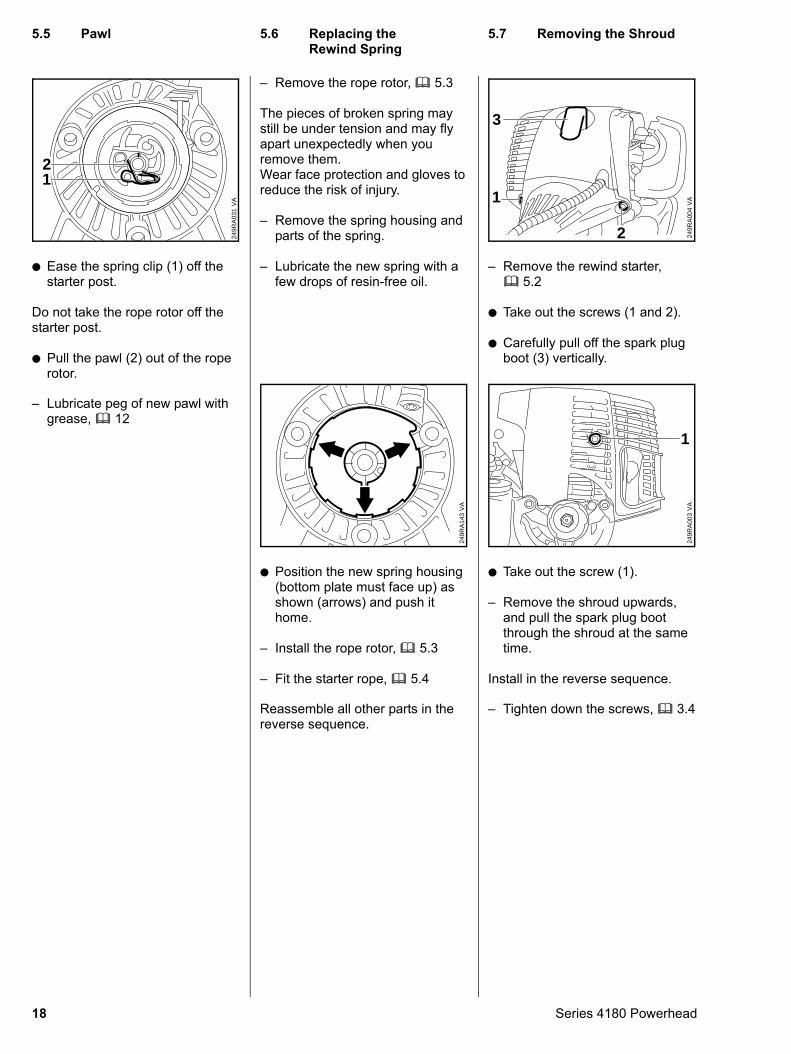
: Ease the spring clip (1) off the starter post.
Do not take the rope rotor off the starter post.
: Pull the pawl (2) out of the rope rotor.
VA
249R
A03
1
12
– Lubricate peg of new pawl with grease, b 12
18
– Remove the rope rotor, b 5.3
The pieces of broken spring may still be under tension and may fly apart unexpectedly when you remove them.Wear face protection and gloves to reduce the risk of injury.
– Remove the spring housing and parts of the spring.
– Lubricate the new spring with a few drops of resin-free oil.
: Position the new spring housing (bottom plate must face up) as shown (arrows) and push it home.
– Install the rope rotor, b 5.3
– Fit the starter rope, b 5.4
VA
249R
A14
3
Reassemble all other parts in the reverse sequence.
– Remove the rewind starter, b 5.2
: Take out the screws (1 and 2).
: Carefully pull off the spark plug boot (3) vertically.
VA
249R
A00
4
3
1
2
: Take out the screw (1).
– Remove the shroud upwards, and pull the spark plug boot through the shroud at the same time.
Install in the reverse sequence.
1
VA
249R
A00
3
– Tighten down the screws, b 3.4
5.5 Pawl
5.6 Replacing the Rewind Spring5.7 Removing the Shroud
Series 4180 Powerhead
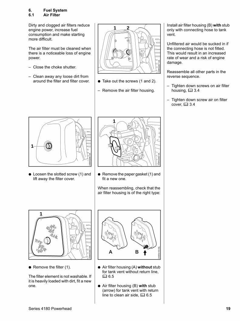
Dirty and clogged air filters reduce engine power, increase fuel consumption and make starting more difficult.
The air filter must be cleaned when there is a noticeable loss of engine power.
– Close the choke shutter.
– Clean away any loose dirt from around the filter and filter cover.
: Loosen the slotted screw (1) and lift away the filter cover.
249R
A00
5
1
VA
: Remove the filter (1).
The filter element is not washable. If it is heavily loaded with dirt, fit a new one.
249R
A00
6
1
VA
Series 4180 Powerhead
: Take out the screws (1 and 2).
– Remove the air filter housing.
VA
249R
A00
7
21
: Remove the paper gasket (1) and fit a new one.
When reassembling, check that the air filter housing is of the right type:
VA
249R
A00
8
1
: Air filter housing (A) without stub for tank vent without return line, b 6.5
: Air filter housing (B) with stub (arrow) for tank vent with return line to clean air side, b 6.5
249R
A18
3 B
L
A B
Install air filter housing (B) with stub only with connecting hose to tank vent.
Unfiltered air would be sucked in if the connecting hose is not fitted. This would result in an increased rate of wear and a risk of engine damage.
Reassemble all other parts in the reverse sequence.
– Tighten down screws on air filter housing, b 3.4
– Tighten down screw air on filter cover, b 3.4
6. Fuel System6.1 Air Filter
19
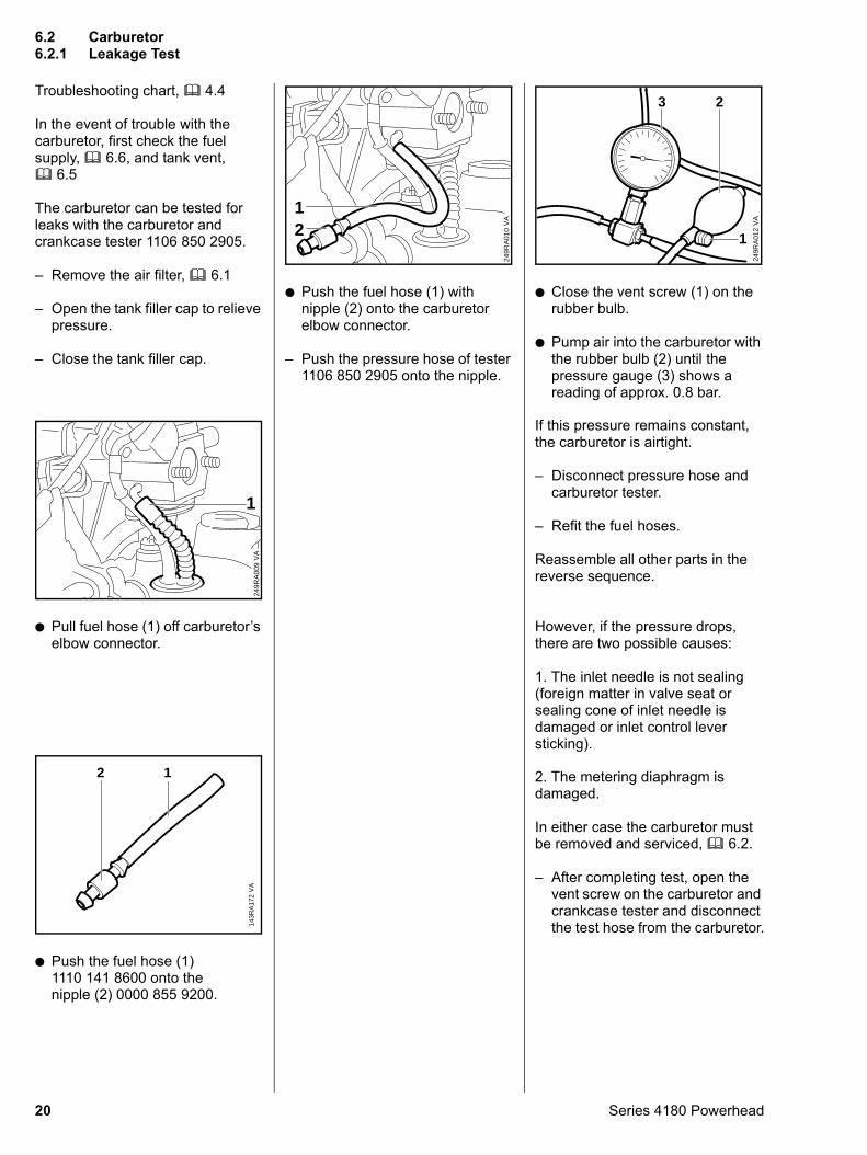
Troubleshooting chart, b 4.4
In the event of trouble with the carburetor, first check the fuel supply, b 6.6, and tank vent, b 6.5
The carburetor can be tested for leaks with the carburetor and crankcase tester 1106 850 2905.
– Remove the air filter, b 6.1
– Open the tank filler cap to relieve pressure.
– Close the tank filler cap.
: Pull fuel hose (1) off carburetor’s elbow connector.
VA
249R
A00
9
1
: Push the fuel hose (1) 1110 141 8600 onto the nipple (2) 0000 855 9200.
VA
143R
A17
2
2 1
20
: Push the fuel hose (1) with nipple (2) onto the carburetor elbow connector.
– Push the pressure hose of tester 1106 850 2905 onto the nipple.
VA
249R
A01
0
12
: Close the vent screw (1) on the rubber bulb.
: Pump air into the carburetor with the rubber bulb (2) until the pressure gauge (3) shows a reading of approx. 0.8 bar.
VA
249R
A01
2
2
1
3
If this pressure remains constant,
the carburetor is airtight.– Disconnect pressure hose and carburetor tester.
– Refit the fuel hoses.
Reassemble all other parts in the reverse sequence.
However, if the pressure drops, there are two possible causes:
1. The inlet needle is not sealing (foreign matter in valve seat or sealing cone of inlet needle is damaged or inlet control lever sticking).
2. The metering diaphragm is damaged.
In either case the carburetor must be removed and serviced, b 6.2.
– After completing test, open the vent screw on the carburetor and crankcase tester and disconnect the test hose from the carburetor.
6.2 Carburetor6.2.1 Leakage Test
Series 4180 Powerhead
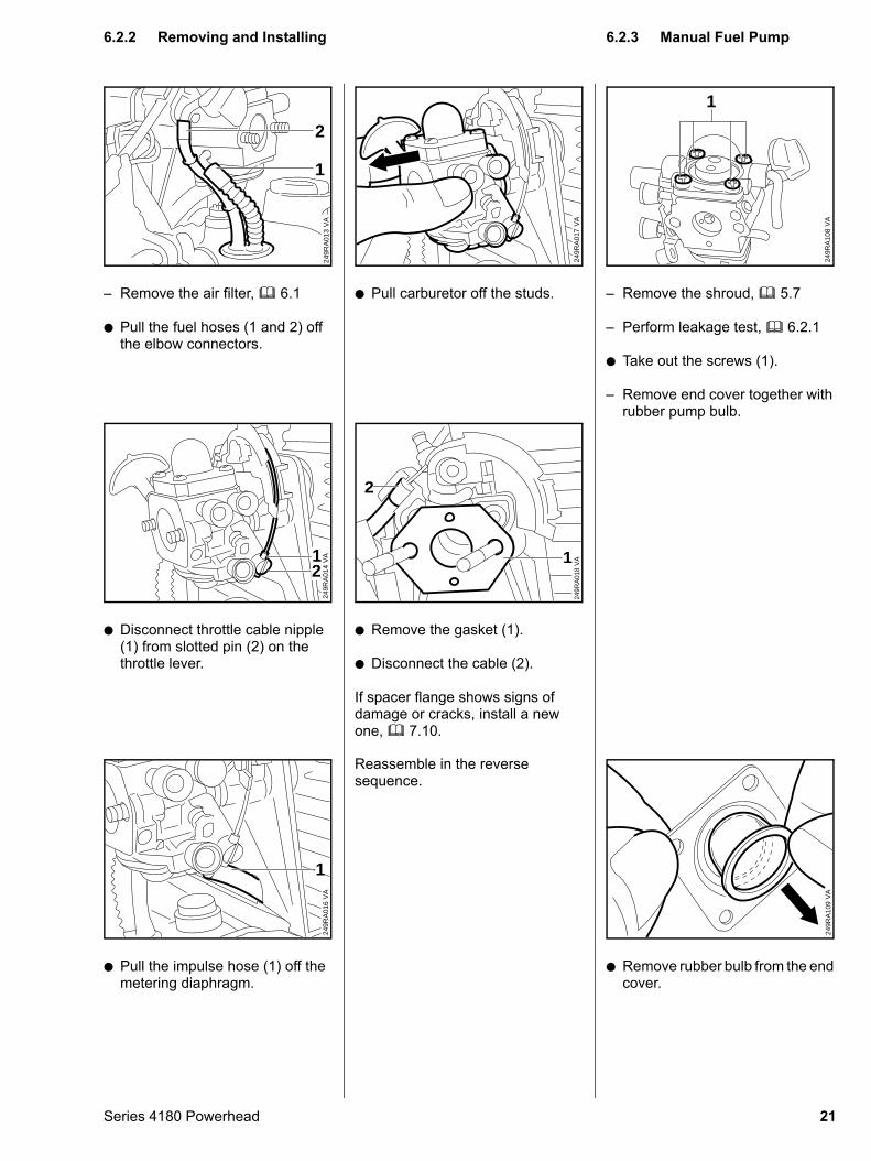
– Remove the air filter, b 6.1
: Pull the fuel hoses (1 and 2) off the elbow connectors.
VA
249R
A01
3
2
1
: Disconnect throttle cable nipple (1) from slotted pin (2) on the throttle lever.
VA
249R
A01
421
: Pull the impulse hose (1) off the metering diaphragm.
VA
249R
A01
6
1
Series 4180 Powerhead
: Pull carburetor off the studs.
VA
249R
A01
7
: Remove the gasket (1).
: Disconnect the cable (2).
If spacer flange shows signs of damage or cracks, install a new one, b 7.10.
VA
249R
A01
8
2
1
Reassemble in the reverse
sequence.– Remove the shroud, b 5.7
– Perform leakage test, b 6.2.1
: Take out the screws (1).
– Remove end cover together with rubber pump bulb.
VA
249R
A10
8
1
: Remove rubber bulb from the end cover.
VA
249R
A10
9
6.2.2 Removing and Installing
6.2.3 Manual Fuel Pump21
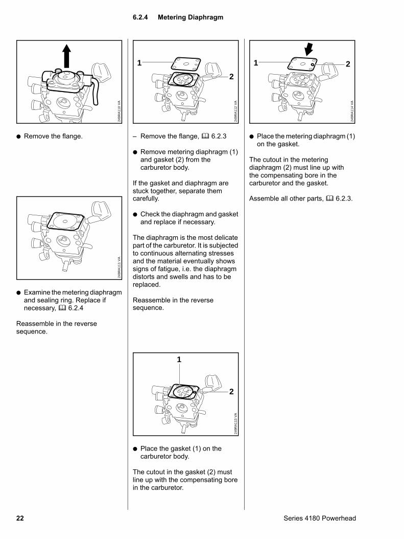
: Remove the flange.
VA
249R
A11
0
: Examine the metering diaphragm and sealing ring. Replace if necessary, b 6.2.4
Reassemble in the reverse sequence.
VA
249R
A11
1
22
– Remove the flange, b 6.2.3
: Remove metering diaphragm (1) and gasket (2) from the carburetor body.
If the gasket and diaphragm are stuck together, separate them
VA
249R
A11
2
1
2
carefully.
: Check the diaphragm and gasket and replace if necessary.
The diaphragm is the most delicate part of the carburetor. It is subjected to continuous alternating stresses and the material eventually shows signs of fatigue, i.e. the diaphragm distorts and swells and has to be replaced.
Reassemble in the reverse sequence.
: Place the gasket (1) on the carburetor body.
The cutout in the gasket (2) must line up with the compensating bore in the carburetor.
VA
249R
A11
3
1
2
: Place the metering diaphragm (1) on the gasket.
The cutout in the metering diaphragm (2) must line up with the compensating bore in the carburetor and the gasket.
VA
249R
A11
4
1 2
Assemble all other parts, b 6.2.3.
6.2.4 Metering Diaphragm
Series 4180 Powerhead
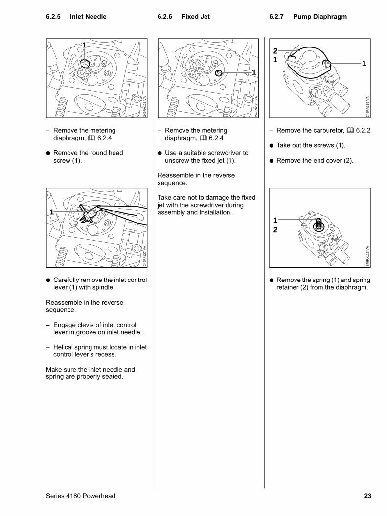
– Remove the metering diaphragm, b 6.2.4
: Remove the round head screw (1).
249R
A12
6V
A
1
: Carefully remove the inlet control lever (1) with spindle.
Reassemble in the reverse sequence.
– Engage clevis of inlet control lever in groove on inlet needle.
249R
A12
7V
A
1
– Helical spring must locate in inlet control lever’s recess.
Make sure the inlet needle and spring are properly seated.
Series 4180 Powerhead
– Remove the metering diaphragm, b 6.2.4
: Use a suitable screwdriver to unscrew the fixed jet (1).
Reassemble in the reverse sequence.
249R
A12
8V
A
1
Take care not to damage the fixed jet with the screwdriver during assembly and installation.
– Remove the carburetor, b 6.2.2
: Take out the screws (1).
: Remove the end cover (2).
VA
249R
A11
5
2
11
: Remove the spring (1) and spring retainer (2) from the diaphragm.
VA
249R
A11
6
12
6.2.5 Inlet Needle
6.2.6 Fixed Jet 6.2.7 Pump Diaphragm23
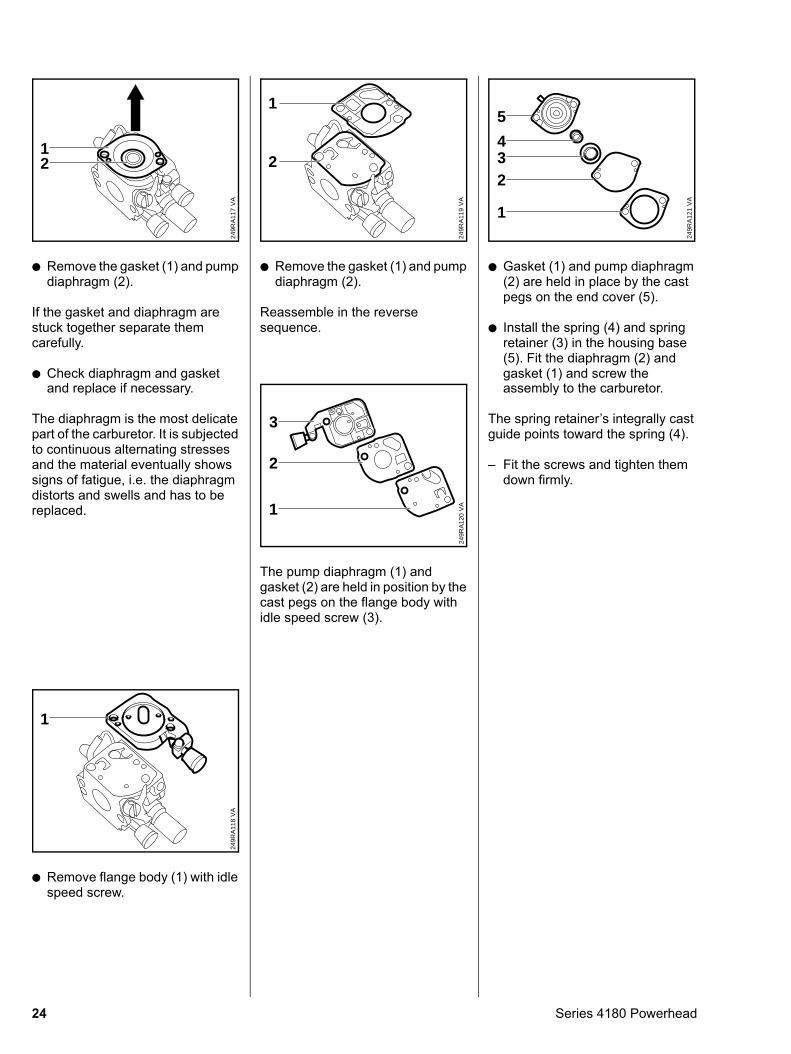
: Remove the gasket (1) and pump diaphragm (2).
If the gasket and diaphragm are stuck together separate them carefully.
: Check diaphragm and gasket
VA
249R
A11
7
12
and replace if necessary.
The diaphragm is the most delicate part of the carburetor. It is subjected to continuous alternating stresses and the material eventually shows signs of fatigue, i.e. the diaphragm distorts and swells and has to be replaced.
: Remove flange body (1) with idle speed screw.
VA
249R
A11
8
1
24
: Remove the gasket (1) and pump diaphragm (2).
Reassemble in the reverse sequence.
VA
249R
A11
9
1
2
The pump diaphragm (1) and gasket (2) are held in position by the cast pegs on the flange body with idle speed screw (3).
VA
249R
A12
0
3
2
1
: Gasket (1) and pump diaphragm (2) are held in place by the cast pegs on the end cover (5).
: Install the spring (4) and spring retainer (3) in the housing base (5). Fit the diaphragm (2) and gasket (1) and screw the
VA
249R
A12
1
5
432
1
assembly to the carburetor.
The spring retainer’s integrally cast guide points toward the spring (4).
– Fit the screws and tighten them down firmly.
Series 4180 Powerhead
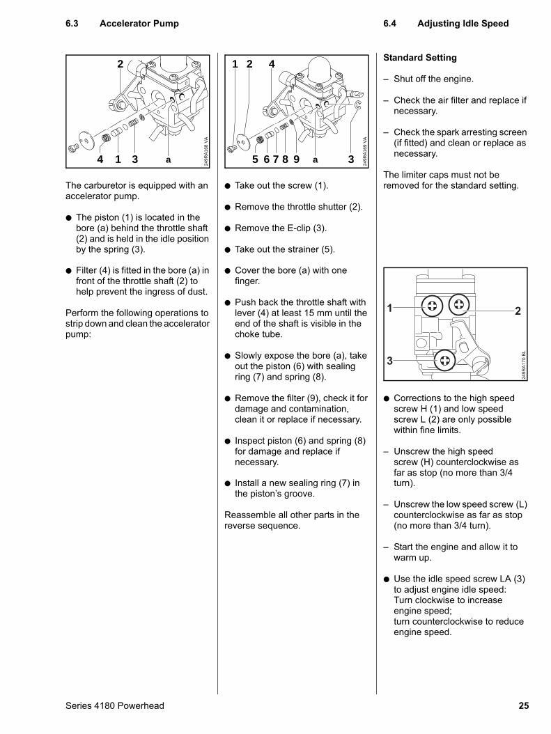
The carburetor is equipped with an accelerator pump.
: The piston (1) is located in the bore (a) behind the throttle shaft (2) and is held in the idle position by the spring (3).
VA
249R
A16
8
2
314 a
: Filter (4) is fitted in the bore (a) in
front of the throttle shaft (2) to help prevent the ingress of dust.Perform the following operations to strip down and clean the accelerator pump:
Series 4180 Powerhead
: Take out the screw (1).
: Remove the throttle shutter (2).
: Remove the E-clip (3).
: Take out the strainer (5).
VA
249R
A16
9
4
98765 3
21
a
: Cover the bore (a) with one
finger.: Push back the throttle shaft with lever (4) at least 15 mm until the end of the shaft is visible in the choke tube.
: Slowly expose the bore (a), take out the piston (6) with sealing ring (7) and spring (8).
: Remove the filter (9), check it for damage and contamination, clean it or replace if necessary.
: Inspect piston (6) and spring (8) for damage and replace if necessary.
: Install a new sealing ring (7) in
the piston’s groove.Reassemble all other parts in the reverse sequence.
Standard Setting
– Shut off the engine.
– Check the air filter and replace if necessary.
– Check the spark arresting screen (if fitted) and clean or replace as necessary.
The limiter caps must not be removed for the standard setting.
: Corrections to the high speed screw H (1) and low speed screw L (2) are only possible within fine limits.
– Unscrew the high speed screw (H) counterclockwise as far as stop (no more than 3/4
249R
A17
0 B
L
1 2
3
turn).
– Unscrew the low speed screw (L) counterclockwise as far as stop (no more than 3/4 turn).
– Start the engine and allow it to warm up.
: Use the idle speed screw LA (3) to adjust engine idle speed:Turn clockwise to increase engine speed;turn counterclockwise to reduce engine speed.
6.3 Accelerator Pump
6.4 Adjusting Idle Speed25
– Adjust engine idle speed with the aid of a tachometer, b 3.1;note that there is an ignition spark on every revolution of the crankshaft.
– Check idling behavior by opening the throttle several times. Make sure engine idles and accelerates smoothly.
If the engine stops while idling:
– Turn the idle speed screw clockwise until the tool begins to move. Then turn the screw back one quarter of a turn from that position.
If the tool runs while the engine is idling:
– Turn idle speed screw counterclockwise until the tool stops running. Then turn the screw about another quarter turn in the same direction.
A slight correction of the setting of the high speed screw (H) may be necessary (no further than stop) if engine power is not satisfactory when operating at high altitude, sea level or after changing the cutting tool.
– Turn the high speed screw H clockwise (leaner) at high altitude or counterclockwise (richer) at sea level.
The limiter caps only need to be removed from the screws if it is necessary to replace the high speed screw (H) or low speed screw (L), clean the carburetor or carry out the basic setting, b 6.4.1.
26
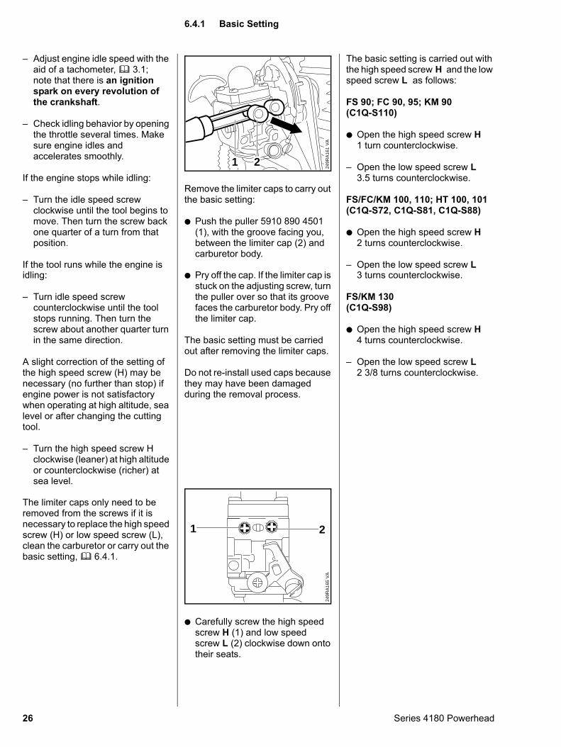
Remove the limiter caps to carry out the basic setting:
: Push the puller 5910 890 4501 (1), with the groove facing you, between the limiter cap (2) and carburetor body.
VA
249R
A16
1
21
: Pry off the cap. If the limiter cap is
stuck on the adjusting screw, turn the puller over so that its groove faces the carburetor body. Pry off the limiter cap.The basic setting must be carried out after removing the limiter caps.
Do not re-install used caps because they may have been damaged during the removal process.
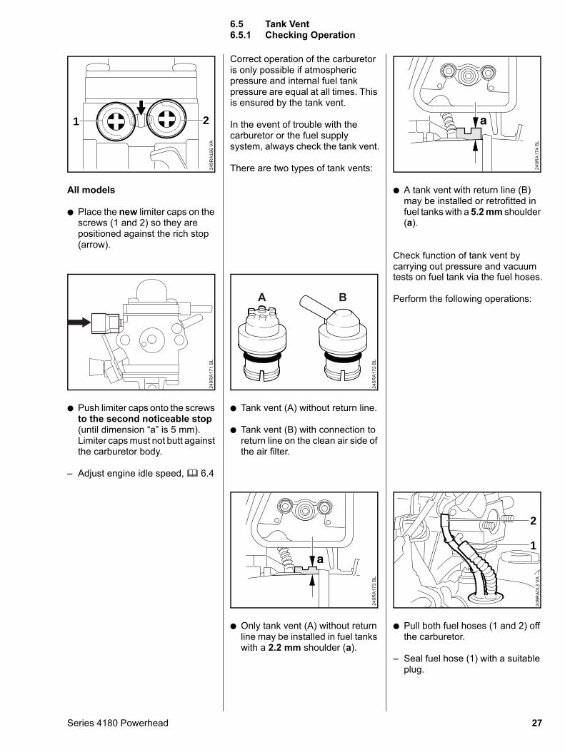
: Carefully screw the high speed screw H (1) and low speed screw L (2) clockwise down onto their seats.
VA
249R
A16
5
21
The basic setting is carried out with the high speed screw H and the low speed screw L as follows:
FS 90; FC 90, 95; KM 90(C1Q-S110)
: Open the high speed screw H 1 turn counterclockwise.
– Open the low speed screw L 3.5 turns counterclockwise.
FS/FC/KM 100, 110; HT 100, 101(C1Q-S72, C1Q-S81, C1Q-S88)
: Open the high speed screw H 2 turns counterclockwise.
– Open the low speed screw L 3 turns counterclockwise.
FS/KM 130(C1Q-S98)
: Open the high speed screw H 4 turns counterclockwise.
– Open the low speed screw L2 3/8 turns counterclockwise.
6.4.1 Basic Setting
Series 4180 Powerhead
All models
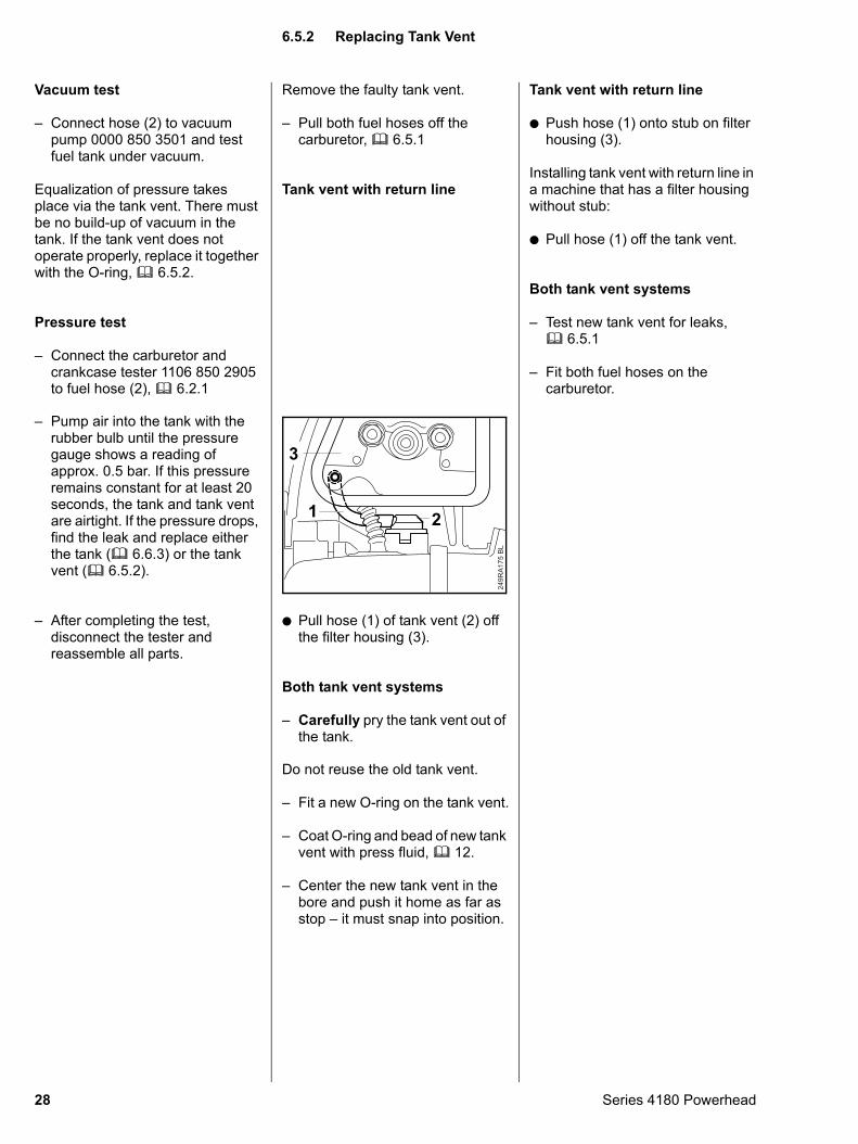
: Place the new limiter caps on the screws (1 and 2) so they are positioned against the rich stop (arrow).
VA
249R
A16
6
21
: Push limiter caps onto the screws to the second noticeable stop (until dimension “a” is 5 mm).Limiter caps must not butt against the carburetor body.
– Adjust engine idle speed, b 6.4
249R
A17
1 B
L
Series 4180 Powerhead
Correct operation of the carburetor is only possible if atmospheric pressure and internal fuel tank pressure are equal at all times. This is ensured by the tank vent.
In the event of trouble with the carburetor or the fuel supply system, always check the tank vent.
There are two types of tank vents:
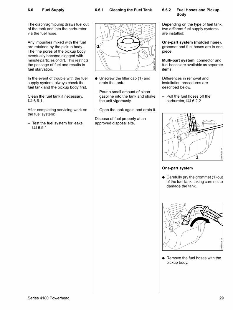
: Tank vent (A) without return line.
: Tank vent (B) with connection to return line on the clean air side of the air filter.
249R
A17
2 B
L
A B
: Only tank vent (A) without return line may be installed in fuel tanks with a 2.2 mm shoulder (a).
249R
A173
BL
: A tank vent with return line (B) may be installed or retrofitted in fuel tanks with a 5.2 mm shoulder (a).
Check function of tank vent by carrying out pressure and vacuum
249R
A174
BL
tests on fuel tank via the fuel hoses.
Perform the following operations:
: Pull both fuel hoses (1 and 2) off the carburetor.
– Seal fuel hose (1) with a suitable plug.
VA
249R
A01
3
2
1
6.5 Tank Vent6.5.1 Checking Operation
27
Vacuum test
– Connect hose (2) to vacuum pump 0000 850 3501 and test fuel tank under vacuum.
Equalization of pressure takes place via the tank vent. There must be no build-up of vacuum in the tank. If the tank vent does not operate properly, replace it together with the O-ring, b 6.5.2.
Pressure test
– Connect the carburetor and crankcase tester 1106 850 2905 to fuel hose (2), b 6.2.1
– Pump air into the tank with the
rubber bulb until the pressure gauge shows a reading of approx. 0.5 bar. If this pressure remains constant for at least 20 seconds, the tank and tank vent are airtight. If the pressure drops, find the leak and replace either the tank (b 6.6.3) or the tank vent (b 6.5.2).– After completing the test, disconnect the tester and reassemble all parts.
28
Remove the faulty tank vent.
– Pull both fuel hoses off the carburetor, b 6.5.1
Tank vent with return line
: Pull hose (1) of tank vent (2) off the filter housing (3).
Both tank vent systems
– Carefully pry the tank vent out of the tank.
249R
A17
5 B
L
1 2
3
Do not reuse the old tank vent.
– Fit a new O-ring on the tank vent.
– Coat O-ring and bead of new tank vent with press fluid, b 12.
– Center the new tank vent in the bore and push it home as far as stop – it must snap into position.
Tank vent with return line
: Push hose (1) onto stub on filter housing (3).
Installing tank vent with return line in a machine that has a filter housing without stub:
: Pull hose (1) off the tank vent.
Both tank vent systems
– Test new tank vent for leaks, b 6.5.1
– Fit both fuel hoses on the carburetor.
6.5.2 Replacing Tank Vent
Series 4180 Powerhead
The diaphragm pump draws fuel out of the tank and into the carburetor via the fuel hose.
Any impurities mixed with the fuel are retained by the pickup body. The fine pores of the pickup body eventually become clogged with minute particles of dirt. This restricts the passage of fuel and results in fuel starvation.
In the event of trouble with the fuel supply system, always check the fuel tank and the pickup body first.
Clean the fuel tank if necessary, b 6.6.1.
After completing servicing work on the fuel system:
– Test the fuel system for leaks, b 6.5.1
Series 4180 Powerhead
: Unscrew the filler cap (1) and drain the tank.
– Pour a small amount of clean gasoline into the tank and shake the unit vigorously.
– Open the tank again and drain it.
VA
249R
A03
3
1
Dispose of fuel properly at an approved disposal site.
Depending on the type of fuel tank, two different fuel supply systems are installed:
One-part system (molded hose), grommet and fuel hoses are in one piece.
Multi-part system, connector and fuel hoses are available as separate items.
Differences in removal and installation procedures are described below.
– Pull the fuel hoses off the carburetor, b 6.2.2
One-part system
: Carefully pry the grommet (1) out of the fuel tank, taking care not to damage the tank.
1
VA
249R
A03
5
: Remove the fuel hoses with the pickup body.
VA
249R
A03
6
6.6 Fuel Supply
6.6.1 Cleaning the Fuel Tank 6.6.2 Fuel Hoses and Pickup Body29
Multi-part system
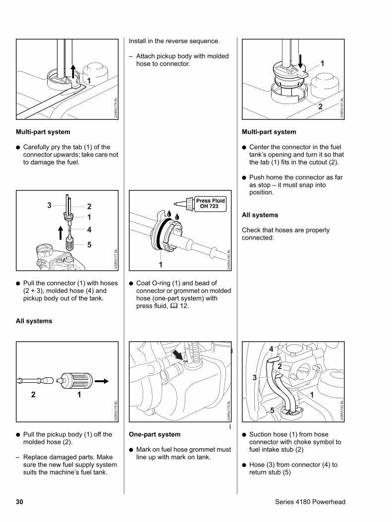
: Carefully pry the tab (1) of the connector upwards; take care not to damage the fuel.
249R
A17
6 B
L
1
: Pull the connector (1) with hoses (2 + 3), molded hose (4) and pickup body out of the tank.
All systems
249R
A177
BL
123
4
5
: Pull the pickup body (1) off the molded hose (2).
– Replace damaged parts. Make sure the new fuel supply system suits the machine’s fuel tank.
249R
A17
8 B
L
2 1
30
Install in the reverse sequence.
– Attach pickup body with molded hose to connector.
: Coat O-ring (1) and bead of connector or grommet on molded hose (one-part system) with press fluid, b 12.
249R
A18
0 B
L
1
d
IOne-part system
: Mark on fuel hose grommet must line up with mark on tank.
249R
A17
9 B
L
Multi-part system
: Center the connector in the fuel tank’s opening and turn it so that the tab (1) fits in the cutout (2).
: Push home the connector as far as stop – it must snap into
249R
A18
1 B
L
1
2
position.
All systems
Check that hoses are properly connected:
: Suction hose (1) from hose connector with choke symbol to fuel intake stub (2)
: Hose (3) from connector (4) to return stub (5)
249R
A182
BL
1
23
4
5
Series 4180 Powerhead
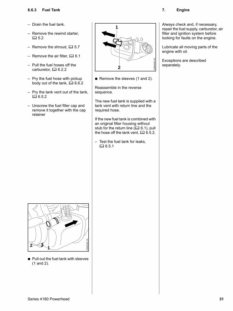
– Drain the fuel tank.
– Remove the rewind starter, b 5.2
– Remove the shroud, b 5.7
– Remove the air filter, b 6.1
– Pull the fuel hoses off the carburetor, b 6.2.2
– Pry the fuel hose with pickup body out of the tank, b 6.6.2
– Pry the tank vent out of the tank, b 6.5.2
– Unscrew the fuel filler cap and remove it together with the cap retainer
: Pull out the fuel tank with sleeves (1 and 2).
1
VA
249R
A03
9
2
Series 4180 Powerhead
: Remove the sleeves (1 and 2).
Reassemble in the reverse sequence.
The new fuel tank is supplied with a tank vent with return line and the required hose.
VA
249R
A04
0
1
2
If the new fuel tank is combined with an original filter housing without stub for the return line (b 6.1), pull the hose off the tank vent, b 6.5.2.
– Test the fuel tank for leaks, b 6.5.1
Always check and, if necessary, repair the fuel supply, carburetor, air filter and ignition system before looking for faults on the engine.
Lubricate all moving parts of the engine with oil.
Exceptions are described separately.
6.6.3 Fuel Tank
7. Engine31
– Pull off the spark plug boot.
– Unscrew the spark plug.
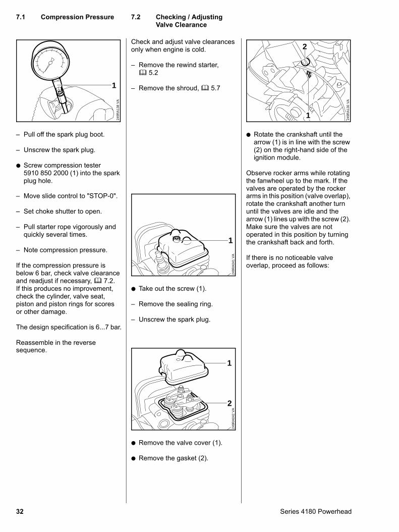
: Screw compression tester 5910 850 2000 (1) into the spark plug hole.
VA
249R
A13
8
1
– Move slide control to "STOP-0".
– Set choke shutter to open.
– Pull starter rope vigorously and quickly several times.
– Note compression pressure.
If the compression pressure is below 6 bar, check valve clearance and readjust if necessary, b 7.2.If this produces no improvement, check the cylinder, valve seat, piston and piston rings for scores or other damage.
The design specification is 6...7 bar.
Reassemble in the reverse sequence.
32
Check and adjust valve clearances only when engine is cold.
– Remove the rewind starter, b 5.2
– Remove the shroud, b 5.7
: Take out the screw (1).
– Remove the sealing ring.
– Unscrew the spark plug.
VA
249R
A04
1
1
: Remove the valve cover (1).
: Remove the gasket (2).
VA
249R
A04
2
1
2
: Rotate the crankshaft until the arrow (1) is in line with the screw (2) on the right-hand side of the ignition module.
Observe rocker arms while rotating the fanwheel up to the mark. If the valves are operated by the rocker
VA
249R
A13
0
2
1
arms in this position (valve overlap),
rotate the crankshaft another turn until the valves are idle and the arrow (1) lines up with the screw (2). Make sure the valves are not operated in this position by turning the crankshaft back and forth.If there is no noticeable valve overlap, proceed as follows:
7.1 Compression Pressure
7.2 Checking / Adjusting Valve ClearanceSeries 4180 Powerhead
: Fit locking screw (1) 4180 890 2700 in spark plug hole.
VA
249R
A04
3
1
– Rotate crankshaft counter-clockwise until the piston butts against the locking screw.
: Remove the hex. nut (1).
: Remove the starter cup (2).
VA
249R
A04
4
12
– Remove the locking screw.
Series 4180 Powerhead
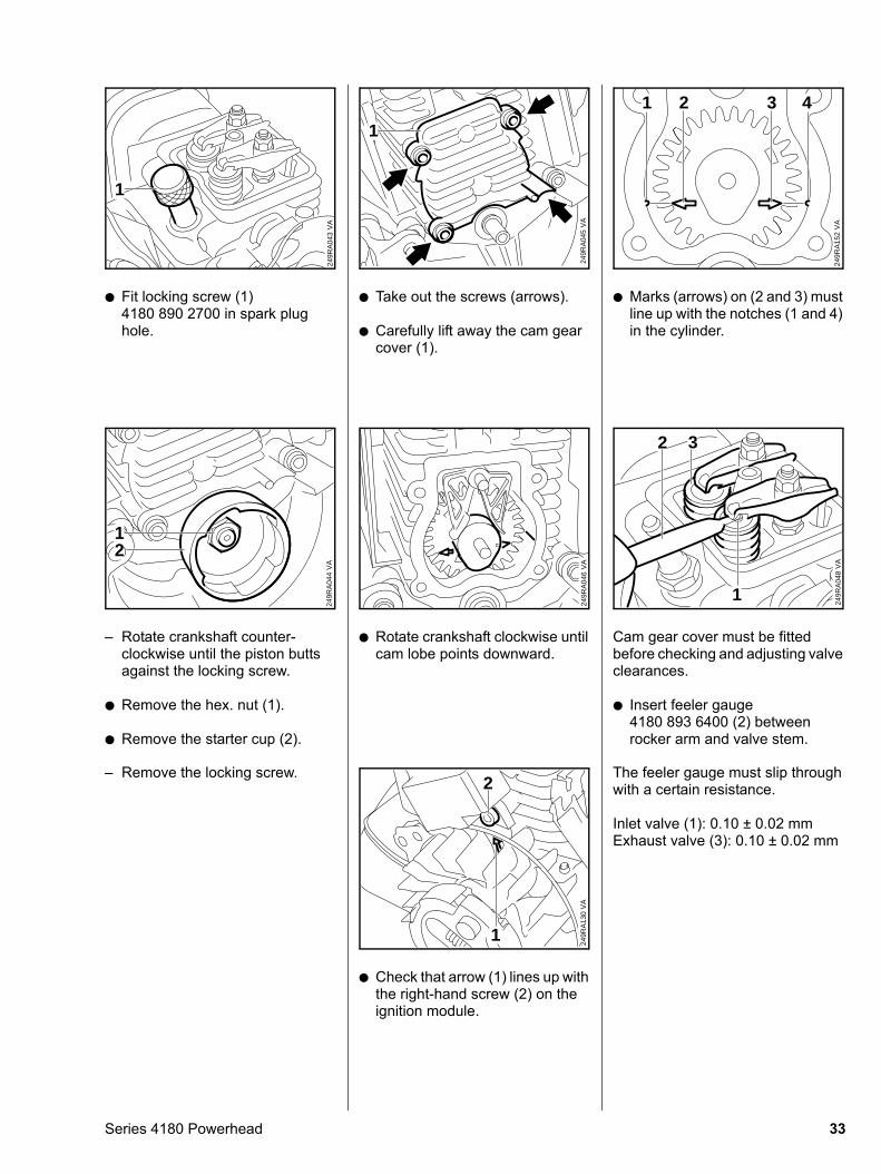
: Take out the screws (arrows).
: Carefully lift away the cam gear cover (1).
VA
249R
A04
5
1
: Rotate crankshaft clockwise until cam lobe points downward.
VA
249R
A04
6
: Check that arrow (1) lines up with the right-hand screw (2) on the ignition module.
VA
249R
A13
0
2
1
: Marks (arrows) on (2 and 3) must line up with the notches (1 and 4) in the cylinder.
VA
249R
A15
2
4321
Cam gear cover must be fitted before checking and adjusting valve clearances.
: Insert feeler gauge 4180 893 6400 (2) between rocker arm and valve stem.
VA
249R
A04
8
1
2 3
The feeler gauge must slip through
with a certain resistance.Inlet valve (1): 0.10 ± 0.02 mmExhaust valve (3): 0.10 ± 0.02 mm
33
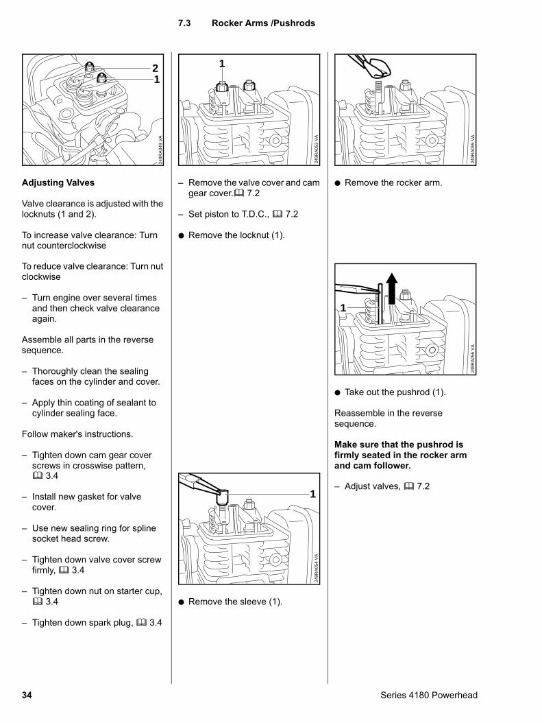
Adjusting Valves
Valve clearance is adjusted with the locknuts (1 and 2).
To increase valve clearance: Turn nut counterclockwise
VA
249R
A04
9
21
To reduce valve clearance: Turn nut
clockwise– Turn engine over several times and then check valve clearance again.
Assemble all parts in the reverse sequence.
– Thoroughly clean the sealing faces on the cylinder and cover.
– Apply thin coating of sealant to cylinder sealing face.
Follow maker's instructions.
– Tighten down cam gear cover screws in crosswise pattern, b 3.4
– Install new gasket for valve cover.
– Use new sealing ring for spline socket head screw.
– Tighten down valve cover screw firmly, b 3.4
– Tighten down nut on starter cup, b 3.4
– Tighten down spark plug, b 3.4
34
– Remove the valve cover and cam gear cover.b 7.2
– Set piston to T.D.C., b 7.2
: Remove the locknut (1).
VA
249R
A05
3
1
: Remove the sleeve (1).
VA
249R
A05
4
1
: Remove the rocker arm.
VA
249R
A05
5
: Take out the pushrod (1).
Reassemble in the reverse sequence.
Make sure that the pushrod is firmly seated in the rocker arm and cam follower.
VA
249R
A05
6
1
– Adjust valves, b 7.2
7.3 Rocker Arms /Pushrods
Series 4180 Powerhead
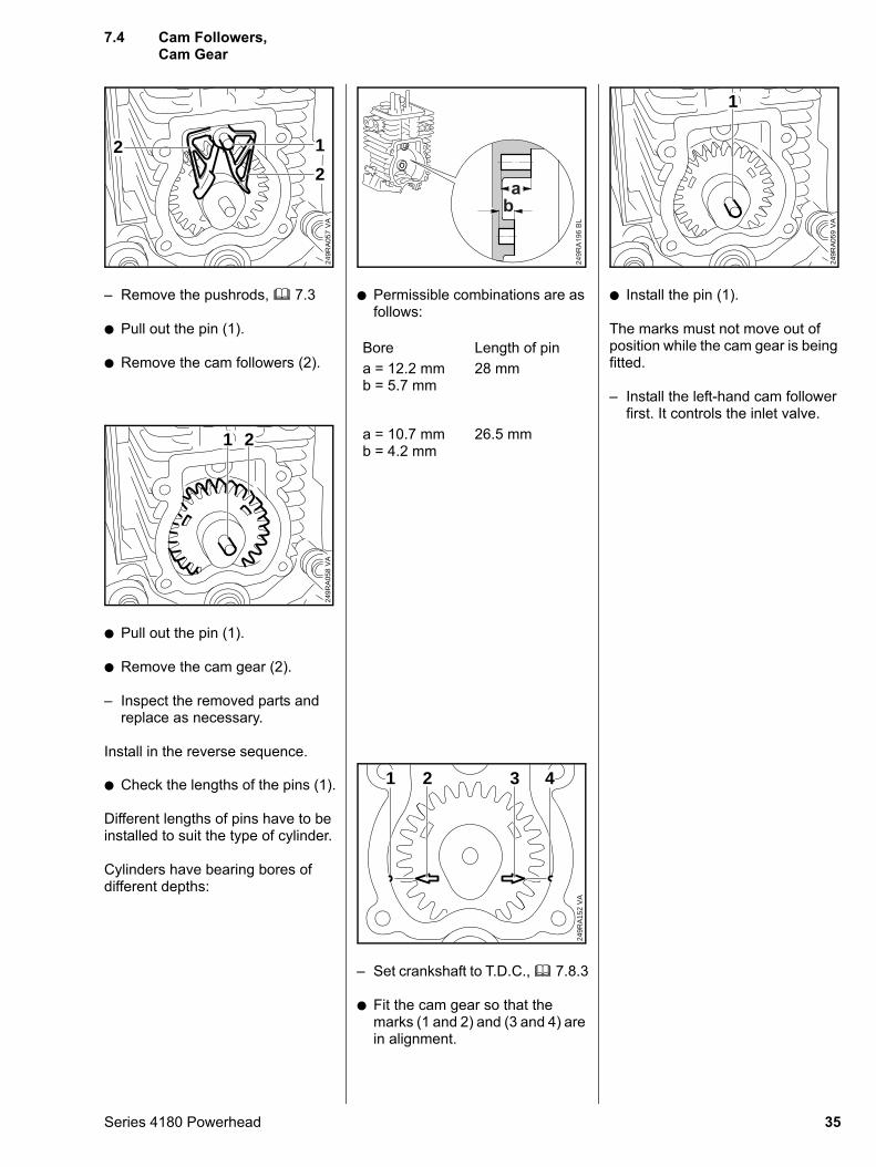
– Remove the pushrods, b 7.3
: Pull out the pin (1).
: Remove the cam followers (2).
VA
249R
A05
7
12
2
: Pull out the pin (1).
: Remove the cam gear (2).
– Inspect the removed parts and replace as necessary.
Install in the reverse sequence.
VA
249R
A05
8
1 2
: Check the lengths of the pins (1).
Different lengths of pins have to be installed to suit the type of cylinder.
Cylinders have bearing bores of different depths:
Series 4180 Powerhead
: Permissible combinations are as follows:
Bore Length of pina = 12.2 mmb = 5.7 mm
28 mm
249R
A19
6 B
L
ab
a = 10.7 mm 26.5 mm
b = 4.2 mm– Set crankshaft to T.D.C., b 7.8.3
: Fit the cam gear so that the marks (1 and 2) and (3 and 4) are in alignment.
VA
249R
A15
2
4321
: Install the pin (1).
The marks must not move out of position while the cam gear is being fitted.
– Install the left-hand cam follower first. It controls the inlet valve.
VA
249R
A05
9
1
7.4 Cam Followers, Cam Gear
35
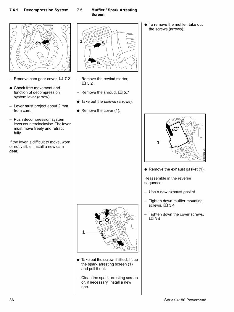
– Remove cam gear cover, b 7.2
: Check free movement and function of decompression system lever (arrow).
– Lever must project about 2 mm from cam.
VA
249R
A14
0
– Push decompression system lever counterclockwise. The lever must move freely and retract fully.
If the lever is difficult to move, worn or not visible, install a new cam gear.
36
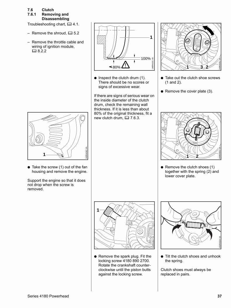
– Remove the rewind starter, b 5.2
– Remove the shroud, b 5.7
: Take out the screws (arrows).
: Remove the cover (1).
VA
249R
A05
0
1
: Take out the screw, if fitted, lift up the spark arresting screen (1) and pull it out.
– Clean the spark arresting screen or, if necessary, install a new one.
VA
249R
A05
1
1
: To remove the muffler, take out the screws (arrows).
: Remove the exhaust gasket (1).
Reassemble in the reverse sequence.
– Use a new exhaust gasket.
– Tighten down muffler mounting V
A24
9RA
052
1
screws, b 3.4
– Tighten down the cover screws, b 3.4
7.4.1 Decompression System
7.5 Muffler / Spark Arresting ScreenSeries 4180 Powerhead
Troubleshooting chart, b 4.1.
– Remove the shroud, b 5.2
– Remove the throttle cable and wiring of ignition module, b 8.2.2
Disassembling
: Take the screw (1) out of the fan housing and remove the engine.
Support the engine so that it does not drop when the screw is removed.
VA
249R
A06
0
1
Series 4180 Powerhead
: Inspect the clutch drum (1). There should be no scores or signs of excessive wear.
If there are signs of serious wear on the inside diameter of the clutch drum, check the remaining wall thickness. If it is less than about
VA
148R
A10
1
80%
100%
1
!
80% of the original thickness, fit a
new clutch drum, b 7.6.3.: Remove the spark plug. Fit the locking screw 4180 890 2700. Rotate the crankshaft counter-clockwise until the piston butts against the locking screw.
VA
249R
A06
4
1
: Take out the clutch shoe screws (1 and 2).
: Remove the cover plate (3).
VA
249R
A06
1
1 23
: Remove the clutch shoes (1) together with the spring (2) and lower cover plate.
VA
249R
A06
3
1 2
: Tilt the clutch shoes and unhook the spring.
Clutch shoes must always be replaced in pairs.
7.6 Clutch7.6.1 Removing and
37
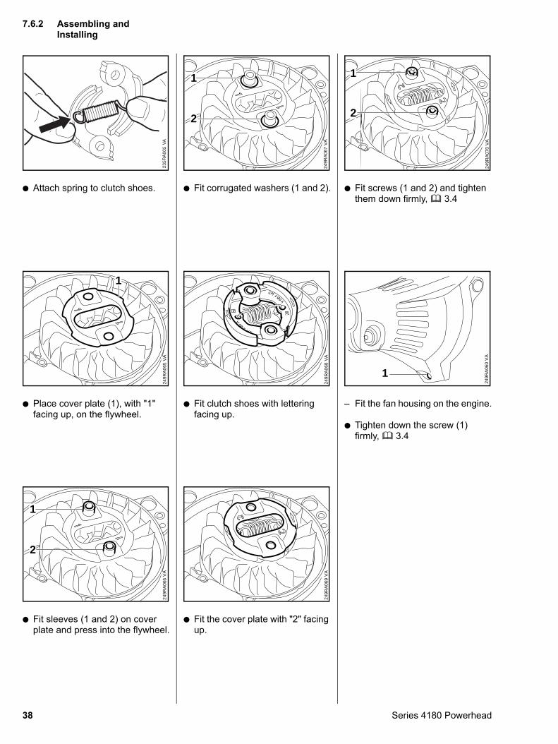
: Attach spring to clutch shoes.
: Place cover plate (1), with "1" facing up, on the flywheel.
VA
249R
A06
5
1
: Fit sleeves (1 and 2) on cover plate and press into the flywheel.
VA
249R
A06
6
1
2
38
: Fit corrugated washers (1 and 2).
VA
249R
A06
7
1
2
: Fit clutch shoes with lettering facing up.
VA
249R
A06
8
: Fit the cover plate with "2" facing up.
VA
249R
A06
9
: Fit screws (1 and 2) and tighten them down firmly, b 3.4
VA
249R
A07
0
2
1
– Fit the fan housing on the engine.
: Tighten down the screw (1) firmly, b 3.4
VA
249R
A06
0
1
7.6.2 Assembling and Installing
Series 4180 Powerhead
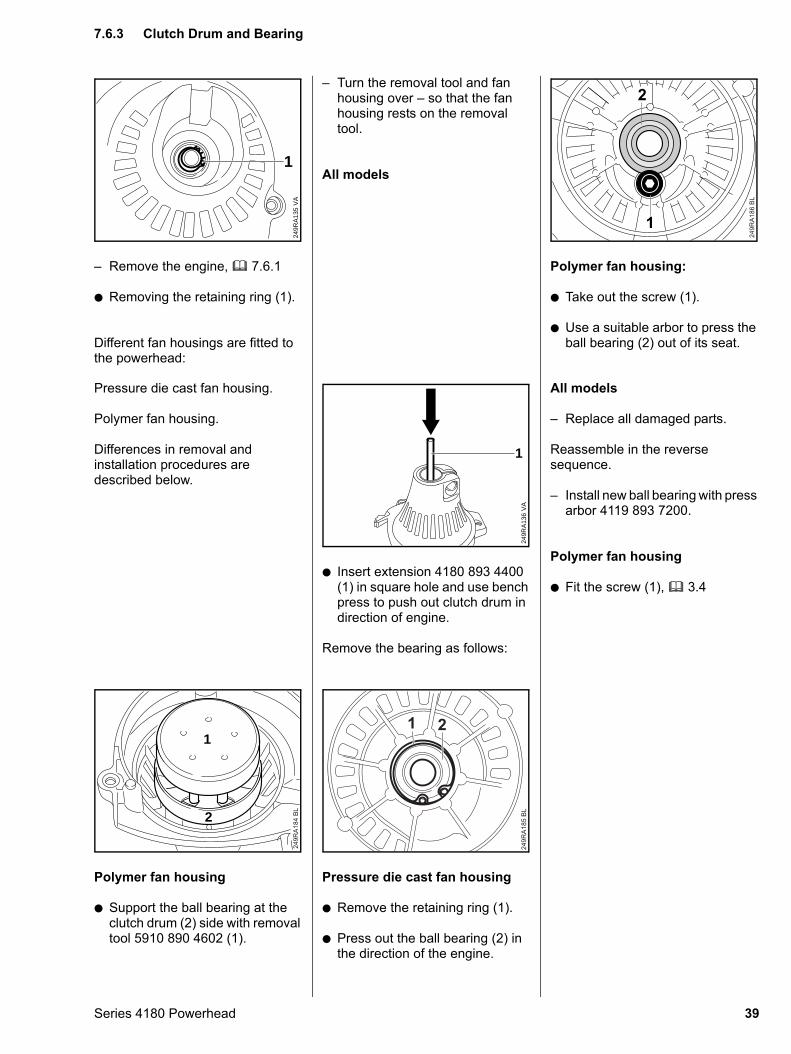
– Remove the engine, b 7.6.1
: Removing the retaining ring (1).
Different fan housings are fitted to the powerhead:
VA
249R
A13
5
1
Pressure die cast fan housing.
Polymer fan housing.
Differences in removal and installation procedures are described below.
Polymer fan housing
: Support the ball bearing at the clutch drum (2) side with removal tool 5910 890 4602 (1).
249R
A184
BL
1
2
Series 4180 Powerhead
– Turn the removal tool and fan housing over – so that the fan housing rests on the removal tool.
All models
: Insert extension 4180 893 4400 (1) in square hole and use bench press to push out clutch drum in direction of engine.
Remove the bearing as follows:
VA
249R
A13
6
1
Pressure die cast fan housing
: Remove the retaining ring (1).
: Press out the ball bearing (2) in the direction of the engine.
249R
A18
5 B
L
1 2
Polymer fan housing:
: Take out the screw (1).
: Use a suitable arbor to press the ball bearing (2) out of its seat.
249R
A18
6 B
L
1
2
All models
– Replace all damaged parts.
Reassemble in the reverse sequence.
– Install new ball bearing with press arbor 4119 893 7200.
Polymer fan housing
: Fit the screw (1), b 3.4
7.6.3 Clutch Drum and Bearing
39
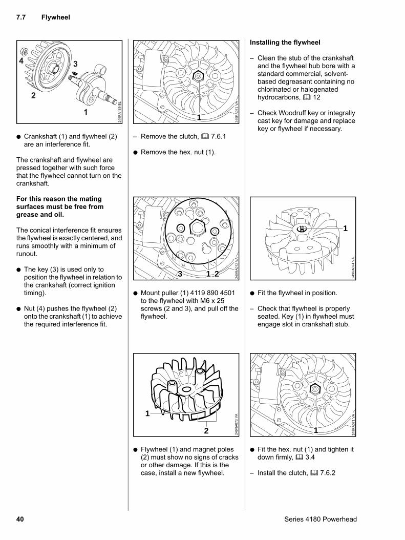
: Crankshaft (1) and flywheel (2) are an interference fit.
The crankshaft and flywheel are pressed together with such force that the flywheel cannot turn on the crankshaft.
249R
A18
9 B
L1
2
34
For this reason the mating
surfaces must be free from grease and oil.The conical interference fit ensures the flywheel is exactly centered, and runs smoothly with a minimum of runout.
: The key (3) is used only to position the flywheel in relation to the crankshaft (correct ignition timing).
: Nut (4) pushes the flywheel (2) onto the crankshaft (1) to achieve the required interference fit.
40
– Remove the clutch, b 7.6.1
: Remove the hex. nut (1).
VA
249R
A07
1
1
: Mount puller (1) 4119 890 4501 to the flywheel with M6 x 25 screws (2 and 3), and pull off the flywheel.
VA
249R
A07
2
23 1
: Flywheel (1) and magnet poles (2) must show no signs of cracks or other damage. If this is the case, install a new flywheel.
VA
249R
A07
3
1
2
Installing the flywheel
– Clean the stub of the crankshaft and the flywheel hub bore with a standard commercial, solvent-based degreasant containing no chlorinated or halogenated hydrocarbons, b 12
– Check Woodruff key or integrally cast key for damage and replace key or flywheel if necessary.
: Fit the flywheel in position.
– Check that flywheel is properly seated. Key (1) in flywheel must engage slot in crankshaft stub.
VA
249R
A07
4
1
: Fit the hex. nut (1) and tighten it down firmly, b 3.4
– Install the clutch, b 7.6.2
VA
249R
A07
1
1
7.7 Flywheel
Series 4180 Powerhead
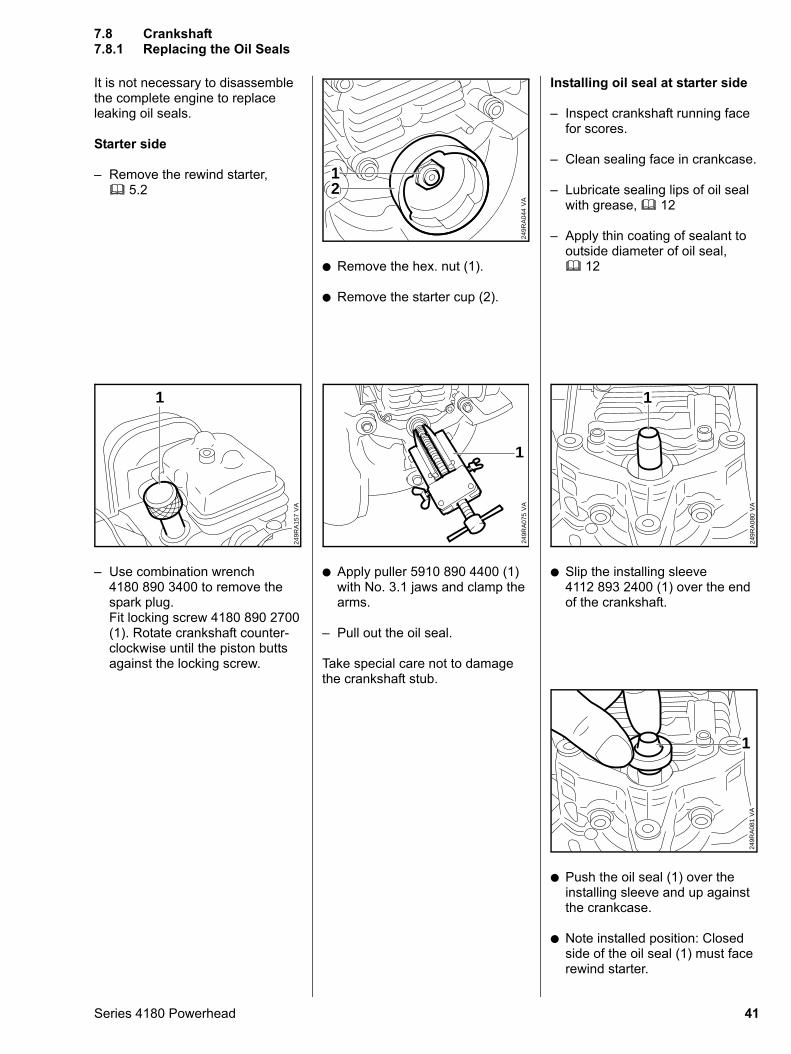
It is not necessary to disassemble the complete engine to replace leaking oil seals.
Starter side
– Remove the rewind starter, b 5.2
– Use combination wrench 4180 890 3400 to remove the spark plug. Fit locking screw 4180 890 2700 (1). Rotate crankshaft counter-clockwise until the piston butts against the locking screw.
VA
249R
A15
7
1
Series 4180 Powerhead
: Remove the hex. nut (1).
: Remove the starter cup (2).
VA
249R
A04
4
12
: Apply puller 5910 890 4400 (1) with No. 3.1 jaws and clamp the arms.
– Pull out the oil seal.
Take special care not to damage the crankshaft stub.
VA
249R
A07
5
1
Installing oil seal at starter side
– Inspect crankshaft running face for scores.
– Clean sealing face in crankcase.
– Lubricate sealing lips of oil seal with grease, b 12
– Apply thin coating of sealant to outside diameter of oil seal, b 12
: Slip the installing sleeve 4112 893 2400 (1) over the end of the crankshaft.
VA
249R
A08
0
1
: Push the oil seal (1) over the installing sleeve and up against the crankcase.
: Note installed position: Closed side of the oil seal (1) must face rewind starter.
VA
249R
A08
11
7.8 Crankshaft7.8.1 Replacing the Oil Seals
41
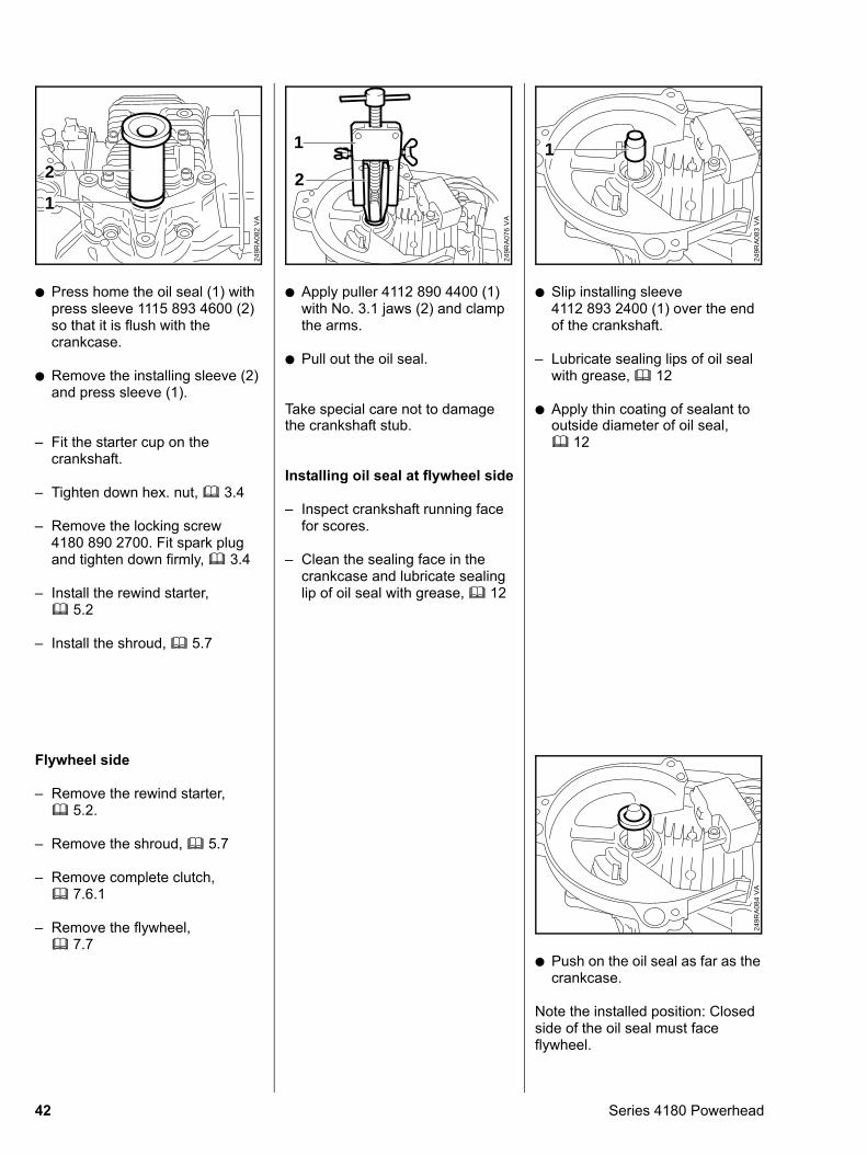
: Press home the oil seal (1) with press sleeve 1115 893 4600 (2) so that it is flush with the crankcase.
: Remove the installing sleeve (2) and press sleeve (1).
VA
249R
A08
2
2
1
– Fit the starter cup on the crankshaft.
– Tighten down hex. nut, b 3.4
– Remove the locking screw 4180 890 2700. Fit spark plug and tighten down firmly, b 3.4
– Install the rewind starter, b 5.2
– Install the shroud, b 5.7
Flywheel side
– Remove the rewind starter, b 5.2.
– Remove the shroud, b 5.7
– Remove complete clutch, b 7.6.1
– Remove the flywheel,b 7.7
42
: Apply puller 4112 890 4400 (1) with No. 3.1 jaws (2) and clamp the arms.
: Pull out the oil seal.
Take special care not to damage
VA
249R
A07
6
2
1
the crankshaft stub.
Installing oil seal at flywheel side
– Inspect crankshaft running face for scores.
– Clean the sealing face in the crankcase and lubricate sealing lip of oil seal with grease, b 12
: Slip installing sleeve 4112 893 2400 (1) over the end of the crankshaft.
– Lubricate sealing lips of oil seal with grease, b 12
: Apply thin coating of sealant to
VA
249R
A08
3
1
outside diameter of oil seal,
b 12: Push on the oil seal as far as the crankcase.
Note the installed position: Closed side of the oil seal must face flywheel.
VA
249R
A08
4
Series 4180 Powerhead
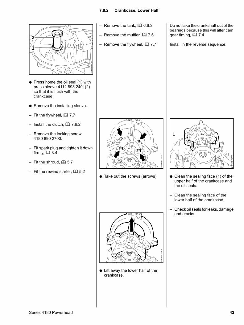
: Press home the oil seal (1) with press sleeve 4112 893 2401(2) so that it is flush with the crankcase.
: Remove the installing sleeve.
– Fit the flywheel, b 7.7
VA
249R
A08
5
1
2
– Install the clutch, b 7.6.2
– Remove the locking screw 4180 890 2700.
– Fit spark plug and tighten it down firmly, b 3.4
– Fit the shroud, b 5.7
– Fit the rewind starter, b 5.2
Series 4180 Powerhead
– Remove the tank, b 6.6.3
– Remove the muffler, b 7.5
– Remove the flywheel, b 7.7
: Take out the screws (arrows).
VA
249R
A07
7
: Lift away the lower half of the crankcase.
VA
249R
A07
8
Do not take the crankshaft out of the bearings because this will alter cam gear timing, b 7.4.
Install in the reverse sequence.
: Clean the sealing face (1) of the upper half of the crankcase and the oil seals.
– Clean the sealing face of the lower half of the crankcase.
– Check oil seals for leaks, damage
VA
249R
A07
9
1
and cracks.
7.8.2 Crankcase, Lower Half
43
– Apply thin coating of sealant to gaskets faces, b 12
: Tighten down screws (arrows) in crosswise pattern, b 3.4
VA
249R
A07
7
44
Always check and, if necessary, repair the fuel system, carburetor, air filter and ignition system before looking for faults on the engine, b 4.1.
– Remove the lower half of the crankcase, b 7.8.2
: Lift the crankshaft (1) and pull the piston out of the cylinder at the same time.
– Pull off the oil seals (2 and 3).
– Inspect cylinder running face for signs of damage and serious
VA
249R
A08
6
3 2 1
scores. Install new cylinder if
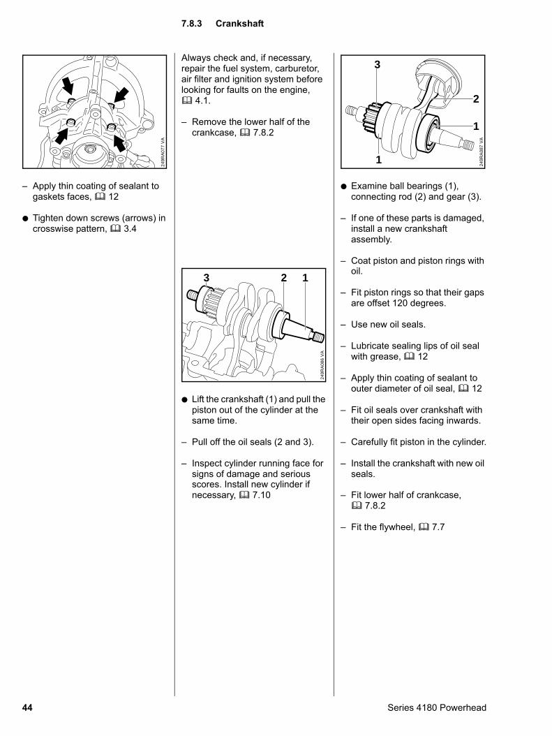
necessary, b 7.10: Examine ball bearings (1), connecting rod (2) and gear (3).
– If one of these parts is damaged, install a new crankshaft assembly.
– Coat piston and piston rings with
VA
249R
A08
7
3
1
2
1
oil.
– Fit piston rings so that their gaps are offset 120 degrees.
– Use new oil seals.
– Lubricate sealing lips of oil seal with grease, b 12
– Apply thin coating of sealant to outer diameter of oil seal, b 12
– Fit oil seals over crankshaft with their open sides facing inwards.
– Carefully fit piston in the cylinder.
– Install the crankshaft with new oil seals.
– Fit lower half of crankcase, b 7.8.2
– Fit the flywheel, b 7.7
7.8.3 Crankshaft
Series 4180 Powerhead
: Rotate flywheel until mark (1) is in line with screw head (2).
– Adjust valve timing, b 7.4V
A24
9RA
130
2
1
Series 4180 Powerhead
– Remove the crankshaft, b 7.8.3
Important:Wear safety glasses when working with spring washers and snap rings.
: Ease the hookless snap ring out of the groove.
VA
249R
A08
8
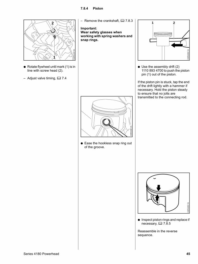
: Use the assembly drift (2) 1110 893 4700 to push the piston pin (1) out of the piston.
If the piston pin is stuck, tap the end of the drift lightly with a hammer if necessary. Hold the piston steady to ensure that no jolts are
VA
249R
A08
9
21
transmitted to the connecting rod.
: Inspect piston rings and replace if necessary, b 7.8.5
Reassemble in the reverse sequence.
VA
249R
A09
0
7.8.4 Piston
45
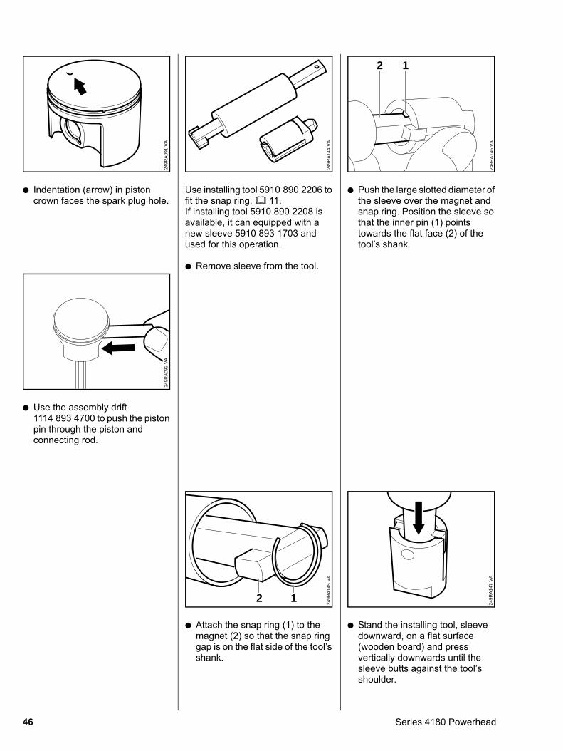
: Indentation (arrow) in piston crown faces the spark plug hole.
VA
249R
A09
1
: Use the assembly drift 1114 893 4700 to push the piston pin through the piston and connecting rod.
VA
249R
A09
2
46
Use installing tool 5910 890 2206 to fit the snap ring, b 11. If installing tool 5910 890 2208 is available, it can equipped with a new sleeve 5910 893 1703 and used for this operation.
: Remove sleeve from the tool.
VA
249R
A14
4
: Attach the snap ring (1) to the magnet (2) so that the snap ring gap is on the flat side of the tool’s shank.
VA
249R
A14
5
2 1
: Push the large slotted diameter of the sleeve over the magnet and snap ring. Position the sleeve so that the inner pin (1) points towards the flat face (2) of the tool’s shank.
VA
249R
A14
6
2 1
: Stand the installing tool, sleeve downward, on a flat surface (wooden board) and press vertically downwards until the sleeve butts against the tool’s shoulder.
VA
249R
A14
7
Series 4180 Powerhead
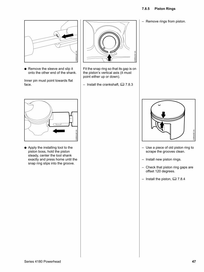
: Remove the sleeve and slip it onto the other end of the shank.
Inner pin must point towards flat face.
VA
249R
A14
8
: Apply the installing tool to the piston boss, hold the piston steady, center the tool shank exactly and press home until the snap ring slips into the groove.
VA
249R
A14
9
Series 4180 Powerhead
Fit the snap ring so that its gap is on the piston’s vertical axis (it must point either up or down).
– Install the crankshaft, b 7.8.3
VA
249R
A15
0
– Remove rings from piston.
– Use a piece of old piston ring to scrape the grooves clean.
– Install new piston rings.
– Check that piston ring gaps are offset 120 degrees.
VA
249R
A09
0
– Install the piston, b 7.8.4
7.8.5 Piston Rings
47
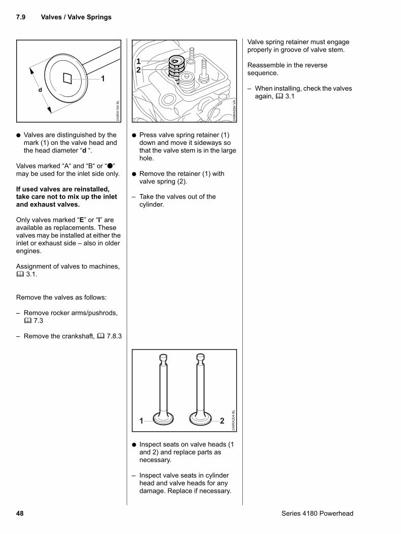
: Valves are distinguished by the mark (1) on the valve head and the head diameter “d “.
Valves marked “A“ and “B“ or “:“ may be used for the inlet side only.
If used valves are reinstalled,
249R
A19
0 B
L
1
take care not to mix up the inlet
and exhaust valves.Only valves marked “E” or “I” are available as replacements. These valves may be installed at either the inlet or exhaust side – also in older engines.
Assignment of valves to machines, b 3.1.
Remove the valves as follows:
– Remove rocker arms/pushrods, b 7.3
– Remove the crankshaft, b 7.8.3
48
: Press valve spring retainer (1) down and move it sideways so that the valve stem is in the large hole.
: Remove the retainer (1) with valve spring (2).
VA
249R
A09
4
12
– Take the valves out of the
cylinder.: Inspect seats on valve heads (1 and 2) and replace parts as necessary.
– Inspect valve seats in cylinder head and valve heads for any damage. Replace if necessary.
249R
A20
4 B
L
1 2
Valve spring retainer must engage properly in groove of valve stem.
Reassemble in the reverse sequence.
– When installing, check the valves again, b 3.1
7.9 Valves / Valve Springs
Series 4180 Powerhead
– Remove the valves, b 7.9
– Remove the cam gear, b 7.4
– Remove the muffler, b 7.5
– Remove the carburetor, b 6.2.2
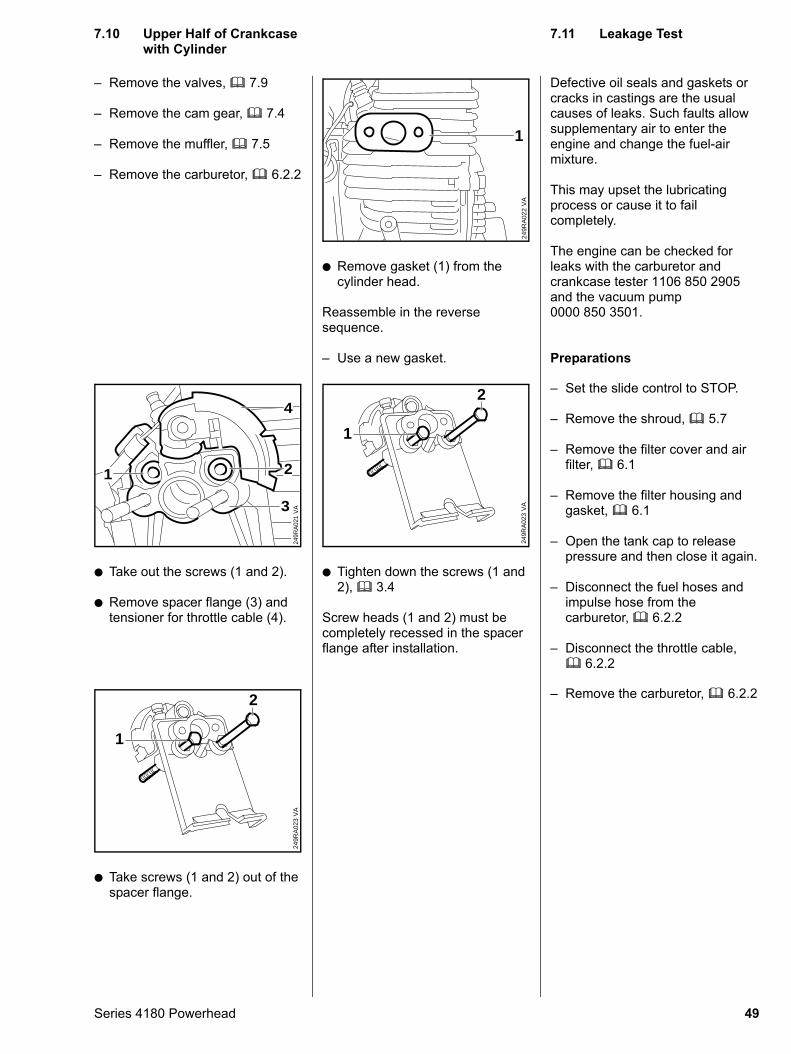
: Take out the screws (1 and 2).
: Remove spacer flange (3) and tensioner for throttle cable (4).
VA
249R
A02
1
1 2
4
3
: Take screws (1 and 2) out of the spacer flange.
VA
249R
A02
3
2
1
Series 4180 Powerhead
: Remove gasket (1) from the cylinder head.
Reassemble in the reverse sequence.
– Use a new gasket.
VA
249R
A02
2
1
: Tighten down the screws (1 and 2), b 3.4
Screw heads (1 and 2) must be completely recessed in the spacer flange after installation.
VA
249R
A02
3
2
1
Defective oil seals and gaskets or cracks in castings are the usual causes of leaks. Such faults allow supplementary air to enter the engine and change the fuel-air mixture.
This may upset the lubricating process or cause it to fail completely.
The engine can be checked for leaks with the carburetor and crankcase tester 1106 850 2905 and the vacuum pump 0000 850 3501.
Preparations
– Set the slide control to STOP.
– Remove the shroud, b 5.7
– Remove the filter cover and air filter, b 6.1
– Remove the filter housing and gasket, b 6.1
– Open the tank cap to release pressure and then close it again.
– Disconnect the fuel hoses and impulse hose from the carburetor, b 6.2.2
– Disconnect the throttle cable, b 6.2.2
– Remove the carburetor, b 6.2.2
7.10 Upper Half of Crankcase with Cylinder
7.11 Leakage Test
49
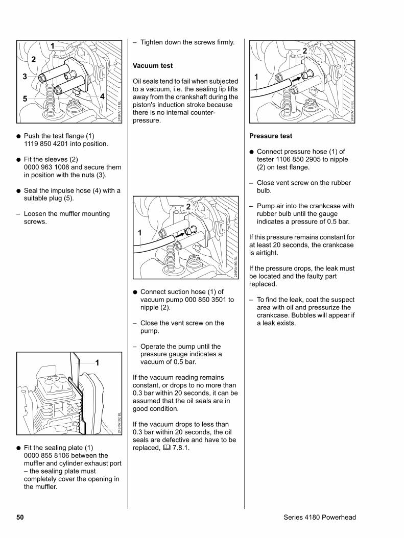
: Push the test flange (1) 1119 850 4201 into position.
: Fit the sleeves (2) 0000 963 1008 and secure them in position with the nuts (3).
: Seal the impulse hose (4) with a
249R
A191
BL
12
3
45
suitable plug (5).
– Loosen the muffler mounting screws.
: Fit the sealing plate (1) 0000 855 8106 between the muffler and cylinder exhaust port – the sealing plate must completely cover the opening in the muffler.
249R
A192
BL
1
50
– Tighten down the screws firmly.
Vacuum test
Oil seals tend to fail when subjected to a vacuum, i.e. the sealing lip lifts away from the crankshaft during the piston's induction stroke because there is no internal counter-pressure.
: Connect suction hose (1) of vacuum pump 000 850 3501 to nipple (2).
– Close the vent screw on the pump.
– Operate the pump until the
249R
A19
3 B
L1
2
pressure gauge indicates a
vacuum of 0.5 bar.If the vacuum reading remains constant, or drops to no more than 0.3 bar within 20 seconds, it can be assumed that the oil seals are in good condition.
If the vacuum drops to less than 0.3 bar within 20 seconds, the oil seals are defective and have to be replaced, b 7.8.1.
Pressure test
: Connect pressure hose (1) of tester 1106 850 2905 to nipple (2) on test flange.
– Close vent screw on the rubber bulb.
249R
A19
3 B
L
1
2
– Pump air into the crankcase with rubber bulb until the gauge indicates a pressure of 0.5 bar.
If this pressure remains constant for at least 20 seconds, the crankcase is airtight.
If the pressure drops, the leak must be located and the faulty part replaced.
– To find the leak, coat the suspect area with oil and pressurize the crankcase. Bubbles will appear if a leak exists.
Series 4180 Powerhead
Exercise extreme caution when carrying out maintenance and repair work on the ignition system. The high voltages which occur can cause serious or even fatal accidents.
Troubleshooting on the ignition system should always begin at the spark plug, b 4.3.
The electronic (breakerless) ignition system basically consists of an ignition module (1) and flywheel (2).
VA
249R
A09
6
2
1
Series 4180 Powerhead
– Remove the shroud, b 5.7
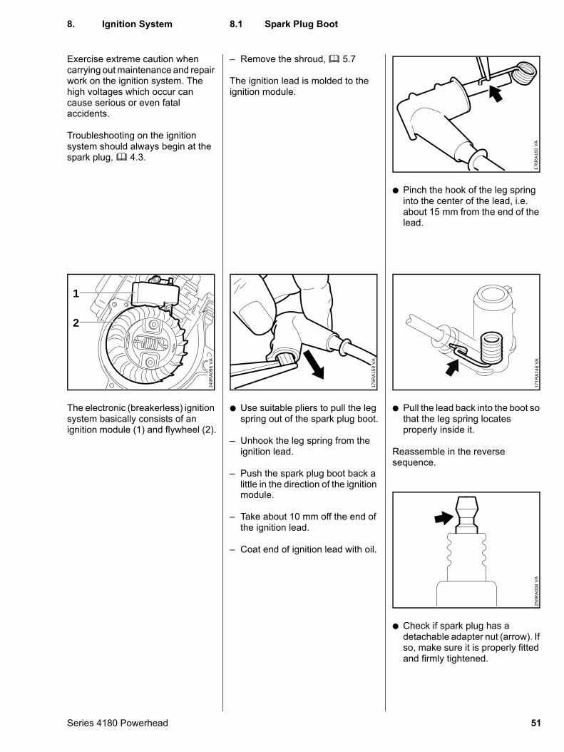
The ignition lead is molded to the ignition module.
: Use suitable pliers to pull the leg spring out of the spark plug boot.
– Unhook the leg spring from the ignition lead.
– Push the spark plug boot back a little in the direction of the ignition
VA
176R
A15
9
module.
– Take about 10 mm off the end of the ignition lead.
– Coat end of ignition lead with oil.
: Pinch the hook of the leg spring into the center of the lead, i.e. about 15 mm from the end of the lead.
VA
176R
A16
0
: Pull the lead back into the boot so that the leg spring locates properly inside it.
Reassemble in the reverse sequence.
VA
171R
A14
6
: Check if spark plug has a detachable adapter nut (arrow). If so, make sure it is properly fitted and firmly tightened.
VA
250R
A00
8
8. Ignition System
8.1 Spark Plug Boot51
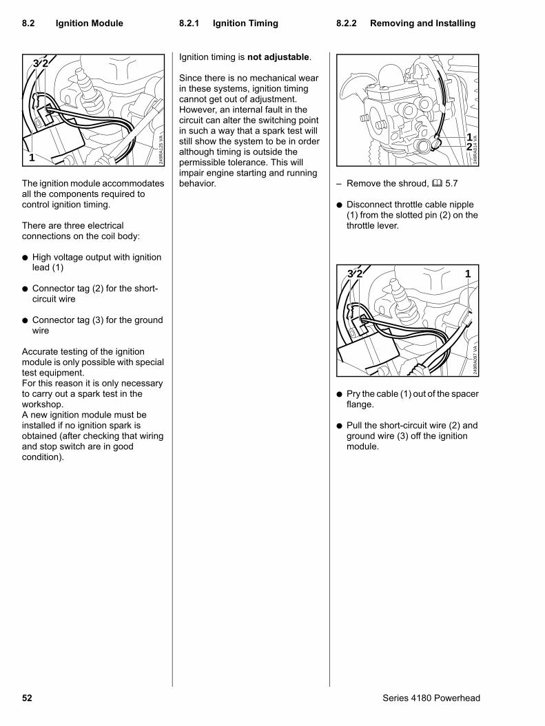
The ignition module accommodates all the components required to control ignition timing.
There are three electrical connections on the coil body:
: High voltage output with ignition
VA
249R
A12
5
3 2
1
lead (1)
: Connector tag (2) for the short-circuit wire
: Connector tag (3) for the ground wire
Accurate testing of the ignition module is only possible with special test equipment.For this reason it is only necessary to carry out a spark test in the workshop.A new ignition module must be installed if no ignition spark is obtained (after checking that wiring and stop switch are in good condition).
52
Ignition timing is not adjustable.
Since there is no mechanical wear in these systems, ignition timing cannot get out of adjustment. However, an internal fault in the circuit can alter the switching point in such a way that a spark test will still show the system to be in order although timing is outside the permissible tolerance. This will impair engine starting and running behavior.
– Remove the shroud, b 5.7: Disconnect throttle cable nipple (1) from the slotted pin (2) on the throttle lever.
VA
249R
A01
421
: Pry the cable (1) out of the spacer flange.
: Pull the short-circuit wire (2) and ground wire (3) off the ignition module.
VA
249R
A09
7
3 2 1
8.2 Ignition Module
8.2.1 Ignition Timing 8.2.2 Removing and InstallingSeries 4180 Powerhead
: Take out screw (1) on fan housing and lift away the engine.
Support the engine while removing the screw.
VA
249R
A06
0
1
: Release and remove screw (1) with connector tag.
: Take out the screw (2) with washer.
: Remove the ignition module.
VA
249R
A09
8
1
2
Series 4180 Powerhead
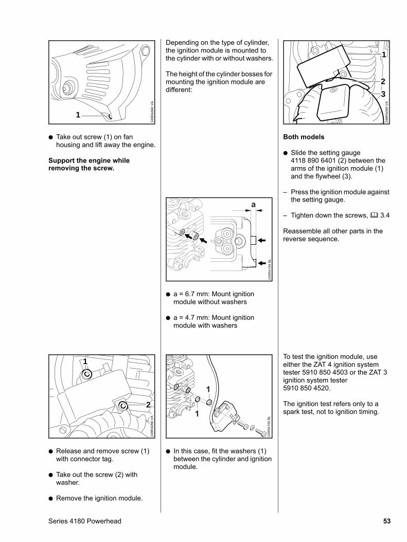
Depending on the type of cylinder, the ignition module is mounted to the cylinder with or without washers.
The height of the cylinder bosses for mounting the ignition module are different:
: a = 6.7 mm: Mount ignition module without washers
: a = 4.7 mm: Mount ignition module with washers
249R
A19
4 B
L
a
: In this case, fit the washers (1) between the cylinder and ignition module.
249R
A19
5 B
L1
1
Both models
: Slide the setting gauge 4118 890 6401 (2) between the arms of the ignition module (1) and the flywheel (3).
– Press the ignition module against
VA
249R
A09
9
1
2
3
the setting gauge.
– Tighten down the screws, b 3.4
Reassemble all other parts in the reverse sequence.
To test the ignition module, use
either the ZAT 4 ignition system tester 5910 850 4503 or the ZAT 3 ignition system tester 5910 850 4520.The ignition test refers only to a spark test, not to ignition timing.
53
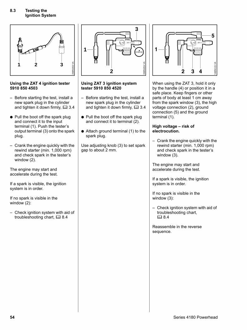
Using the ZAT 4 ignition tester5910 850 4503
– Before starting the test, install a new spark plug in the cylinder and tighten it down firmly, b 3.4
: Pull the boot off the spark plug
VA
208R
A05
3321
and connect it to the input
terminal (1). Push the tester’s output terminal (3) onto the spark plug.– Crank the engine quickly with the rewind starter (min. 1,000 rpm) and check spark in the tester’s window (2).
The engine may start and accelerate during the test.
If a spark is visible, the ignition system is in order.
If no spark is visible in the window (2):
– Check ignition system with aid of troubleshooting chart, b 8.4
54
Using ZAT 3 ignition system tester 5910 850 4520
– Before starting the test, install a new spark plug in the cylinder and tighten it down firmly, b 3.4
: Pull the boot off the spark plug
VA
208R
A05
4
ZAT 3
5910 850 4520
3
2
1
and connect it to terminal (2).
: Attach ground terminal (1) to the spark plug.
Use adjusting knob (3) to set spark gap to about 2 mm.
When using the ZAT 3, hold it only by the handle (4) or position it in a safe place. Keep fingers or other parts of body at least 1 cm away from the spark window (3), the high voltage connection (2), ground connection (5) and the ground terminal (1).
High voltage – risk of electrocution.
– Crank the engine quickly with the rewind starter (min. 1,000 rpm) and check spark in the tester’s window (3).
The engine may start and accelerate during the test.
If a spark is visible, the ignition system is in order.
If no spark is visible in the window (3):
– Check ignition system with aid of troubleshooting chart, b 8.4
Reassemble in the reverse sequence.
8.3 Testing the Ignition System
Series 4180 Powerhead
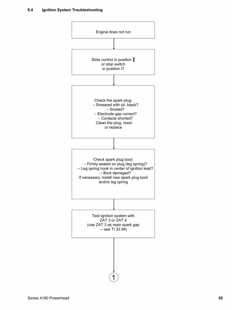
8.4 Ignition System Troubleshooting
Engine does not run
Slide control in position # or stop switchin position I?
Check the spark plug:– Smeared with oil, black?
– Sooted?– Electrode gap correct?
– Contacts shorted? Clean the plug, reset
or replace
Check spark plug boot:– Firmly seated on plug (leg spring)?
– Leg spring hook in center of ignition lead?– Boot damaged?
If necessary, install new spark plug boot and/or leg spring
Test ignition system with ZAT 3 or ZAT 4
(use ZAT 3 as main spark gap – see TI 32.94)
1
55Series 4180 Powerhead
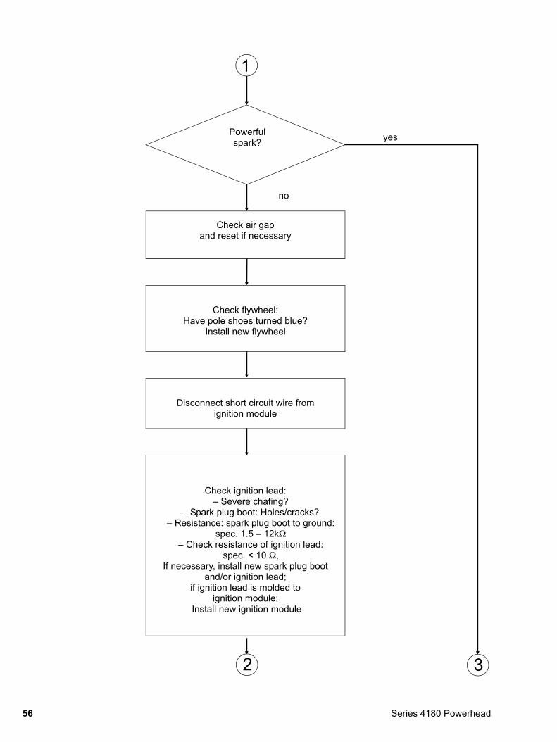
Check flywheel: Have pole shoes turned blue?
Install new flywheel
Check air gapand reset if necessary
Check ignition lead:– Severe chafing?
– Spark plug boot: Holes/cracks?– Resistance: spark plug boot to ground:
spec. 1.5 – 12kΩ – Check resistance of ignition lead:
spec. < 10 Ω, If necessary, install new spark plug boot
and/or ignition lead;if ignition lead is molded to
ignition module: Install new ignition module
Disconnect short circuit wire from ignition module
1
3
yes
no
2
Powerfulspark?
56 Series 4180 Powerhead
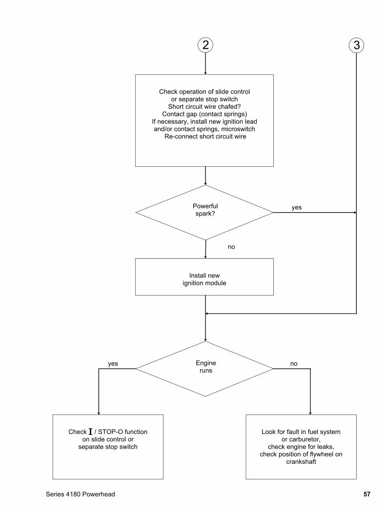
Check # / STOP-O functionon slide control or
separate stop switch
no
Install newignition module
yes
no
Look for fault in fuel system or carburetor,
check engine for leaks, check position of flywheel on
crankshaft
yes
Check operation of slide control or separate stop switch
Short circuit wire chafed?Contact gap (contact springs)
If necessary, install new ignition lead and/or contact springs, microswitch
Re-connect short circuit wire
2 3
Powerfulspark?
Engineruns
57Series 4180 Powerhead
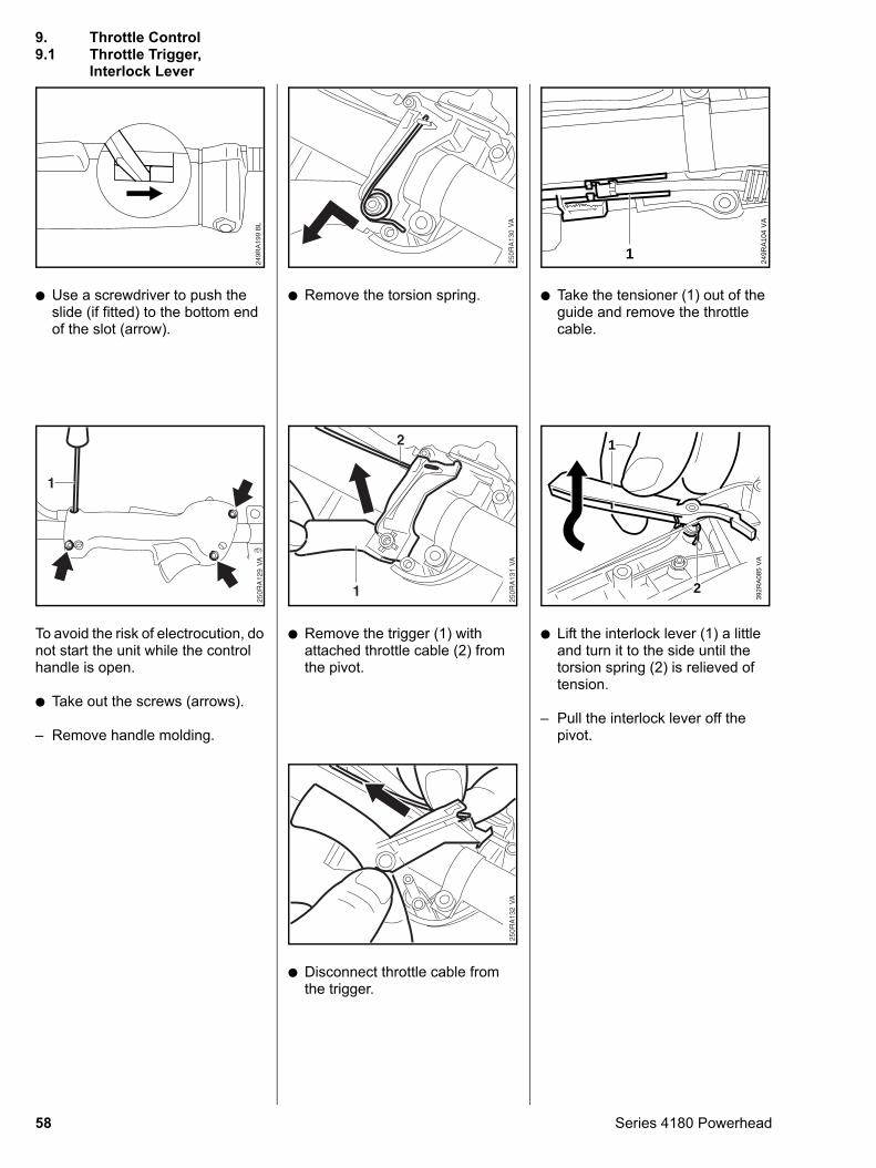
: Use a screwdriver to push the slide (if fitted) to the bottom end of the slot (arrow).
249R
A19
9 B
L
Interlock Lever
To avoid the risk of electrocution, do not start the unit while the control handle is open.
: Take out the screws (arrows).
– Remove handle molding.
58
: Remove the torsion spring.
: Remove the trigger (1) with attached throttle cable (2) from the pivot.
: Disconnect throttle cable from the trigger.
: Take the tensioner (1) out of the guide and remove the throttle cable.
VA
249R
A10
4
1
: Lift the interlock lever (1) a little and turn it to the side until the torsion spring (2) is relieved of tension.
– Pull the interlock lever off the pivot.
392R
A08
5V
A
1
2
9. Throttle Control9.1 Throttle Trigger,
Series 4180 Powerhead
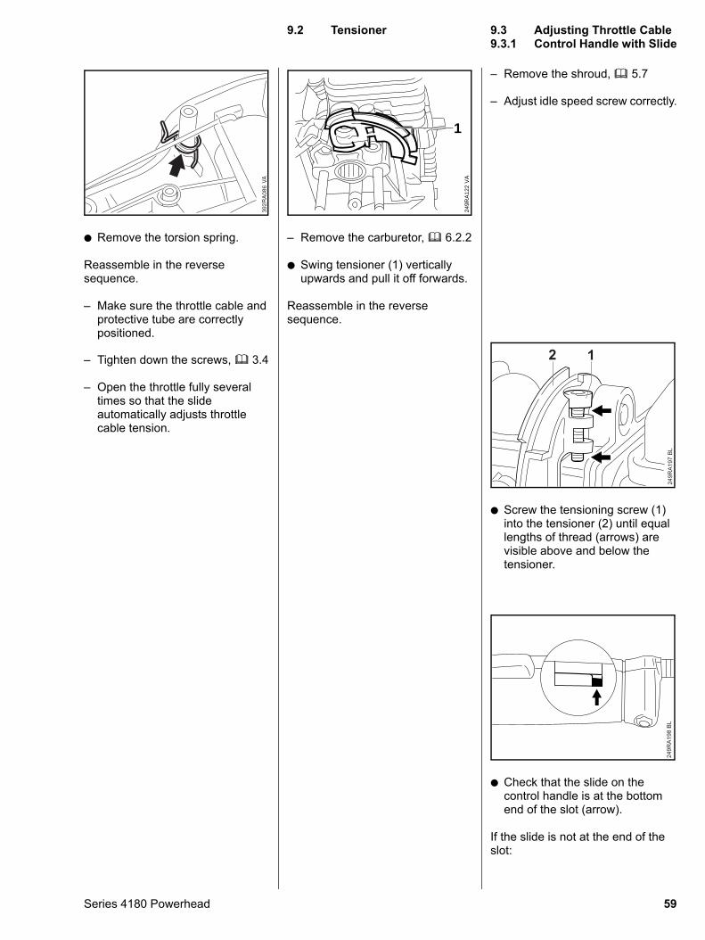
: Remove the torsion spring.
Reassemble in the reverse sequence.
– Make sure the throttle cable and protective tube are correctly positioned.
– Tighten down the screws, b 3.4
– Open the throttle fully several times so that the slide automatically adjusts throttle cable tension.
Series 4180 Powerhead
– Remove the carburetor, b 6.2.2
: Swing tensioner (1) vertically upwards and pull it off forwards.
Reassemble in the reverse sequence.
VA
249R
A12
2
1
– Remove the shroud, b 5.7
– Adjust idle speed screw correctly.
: Screw the tensioning screw (1) into the tensioner (2) until equal lengths of thread (arrows) are visible above and below the tensioner.
249R
A19
7 B
L
2 1
: Check that the slide on the control handle is at the bottom end of the slot (arrow).
If the slide is not at the end of the slot:
249R
A19
8 B
L
9.2 Tensioner
9.3 Adjusting Throttle Cable9.3.1 Control Handle with Slide59
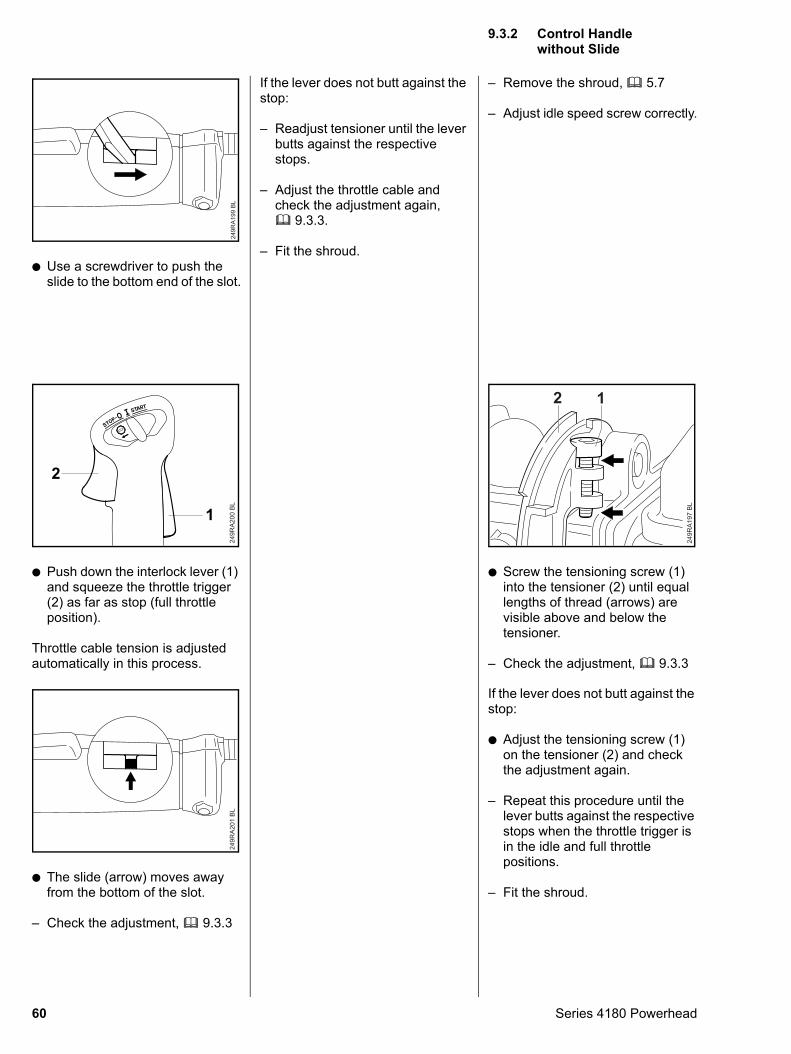
: Use a screwdriver to push the slide to the bottom end of the slot.
249R
A19
9 B
L
: Push down the interlock lever (1) and squeeze the throttle trigger (2) as far as stop (full throttle position).
Throttle cable tension is adjusted automatically in this process.
249R
A200
BL
STOP
1
2
: The slide (arrow) moves away from the bottom of the slot.
– Check the adjustment, b 9.3.3
249R
A20
1 B
L
60
If the lever does not butt against the stop:
– Readjust tensioner until the lever butts against the respective stops.
– Adjust the throttle cable and check the adjustment again, b 9.3.3.
– Fit the shroud.
– Remove the shroud, b 5.7
– Adjust idle speed screw correctly.
: Screw the tensioning screw (1) into the tensioner (2) until equal lengths of thread (arrows) are visible above and below the tensioner.
– Check the adjustment, b 9.3.3
249R
A19
7 B
L
2 1
If the lever does not butt against the
stop:: Adjust the tensioning screw (1) on the tensioner (2) and check the adjustment again.
– Repeat this procedure until the lever butts against the respective stops when the throttle trigger is in the idle and full throttle positions.
– Fit the shroud.
9.3.2 Control Handle without Slide
Series 4180 Powerhead
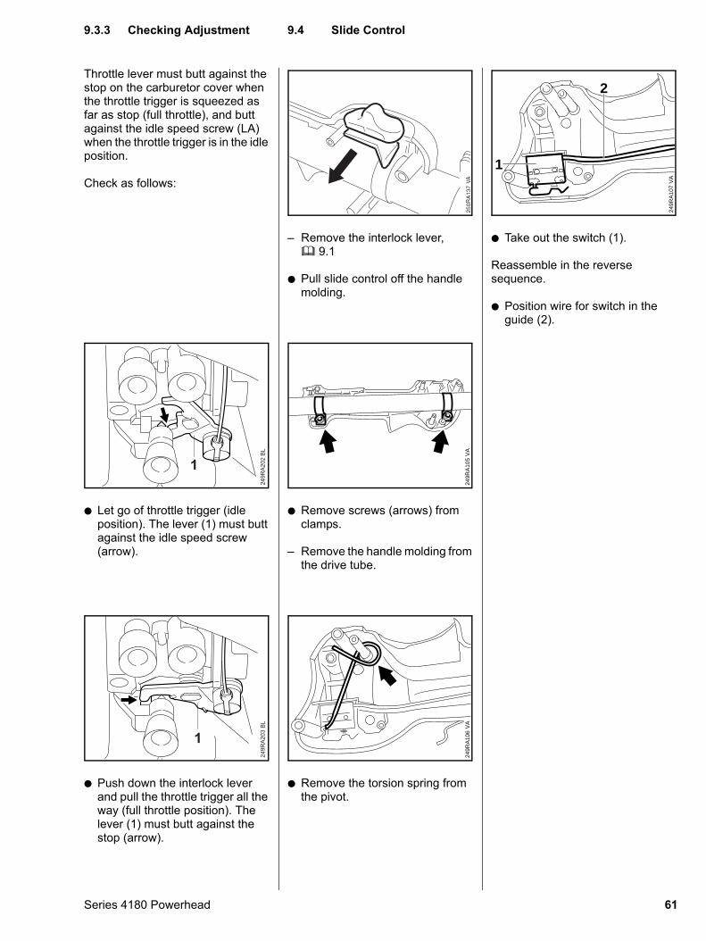
Throttle lever must butt against the stop on the carburetor cover when the throttle trigger is squeezed as far as stop (full throttle), and butt against the idle speed screw (LA) when the throttle trigger is in the idle position.
Check as follows:
: Let go of throttle trigger (idle position). The lever (1) must butt against the idle speed screw (arrow).
249R
A202
BL
1
: Push down the interlock lever and pull the throttle trigger all the way (full throttle position). The lever (1) must butt against the stop (arrow).
249R
A203
BL
1
Series 4180 Powerhead
– Remove the interlock lever, b 9.1
: Pull slide control off the handle molding.
: Remove screws (arrows) from clamps.
– Remove the handle molding from the drive tube.
VA
249R
A10
5
: Remove the torsion spring from the pivot.
VA
249R
A10
6
: Take out the switch (1).
Reassemble in the reverse sequence.
: Position wire for switch in the guide (2).
VA
249R
A10
7
1
2
9.3.3 Checking Adjustment
9.4 Slide Control61
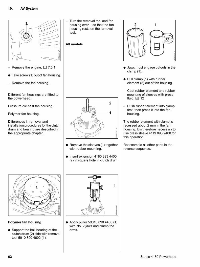
– Remove the engine, b 7.6.1
: Take screw (1) out of fan housing.
– Remove the fan housing.
Different fan housings are fitted to
VA
249R
A13
1
1
the powerhead:
Pressure die cast fan housing.
Polymer fan housing.
Differences in removal and installation procedures for the clutch drum and bearing are described in the appropriate chapter.
Polymer fan housing
: Support the ball bearing at the clutch drum (2) side with removal tool 5910 890 4602 (1).
249R
A184
BL
1
2
62
– Turn the removal tool and fan housing over – so that the fan housing rests on the removal tool.
All models
: Remove the sleeves (1) together with rubber mounting.
: Insert extension 4180 893 4400 (2) in square hole in clutch drum.
249R
A187
BL
2
1
: Apply puller 59010 890 4400 (1) with No. 2 jaws and clamp the arms.
VA
249R
A13
3
1
: Jaws must engage cutouts in the clamp (1).
: Pull clamp (1) with rubber element (2) out of fan housing.
– Coat rubber element and rubber mounting of sleeves with press
249R
A18
8 B
L
12
fluid, b 12
– Push rubber element into clamp first, then press it into the fan housing.
The rubber element with clamp is recessed about 2 mm in the fan housing. It is therefore necessary to use press sleeve 4119 893 2400 for this operation.
Reassemble all other parts in the reverse sequence.
10. AV System
Series 4180 Powerhead
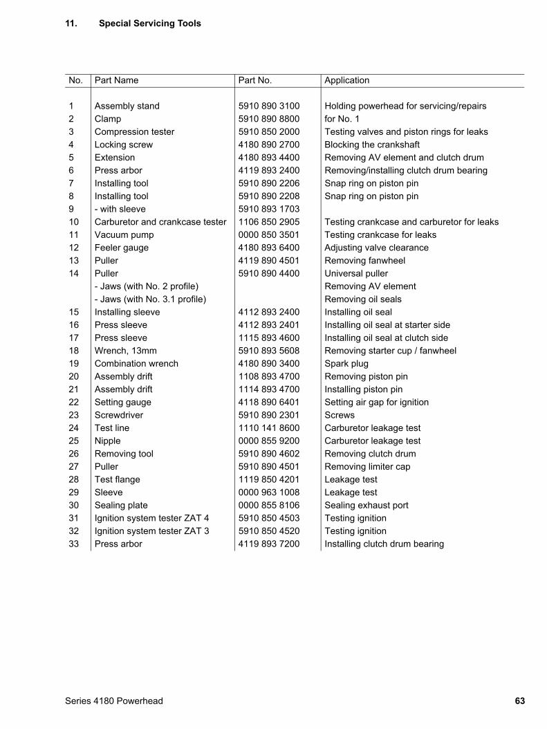
11. Special Servicing Tools
No. Part Name Part No. Application
1 Assembly stand 5910 890 3100 Holding powerhead for servicing/repairs2 Clamp 5910 890 8800 for No. 13 Compression tester 5910 850 2000 Testing valves and piston rings for leaks4 Locking screw 4180 890 2700 Blocking the crankshaft5 Extension 4180 893 4400 Removing AV element and clutch drum6 Press arbor 4119 893 2400 Removing/installing clutch drum bearing7 Installing tool 5910 890 2206 Snap ring on piston pin8 Installing tool 5910 890 2208 Snap ring on piston pin9 - with sleeve 5910 893 170310 Carburetor and crankcase tester 1106 850 2905 Testing crankcase and carburetor for leaks11 Vacuum pump 0000 850 3501 Testing crankcase for leaks12 Feeler gauge 4180 893 6400 Adjusting valve clearance13 Puller 4119 890 4501 Removing fanwheel14 Puller 5910 890 4400 Universal puller
- Jaws (with No. 2 profile) Removing AV element- Jaws (with No. 3.1 profile) Removing oil seals
15 Installing sleeve 4112 893 2400 Installing oil seal16 Press sleeve 4112 893 2401 Installing oil seal at starter side17 Press sleeve 1115 893 4600 Installing oil seal at clutch side18 Wrench, 13mm 5910 893 5608 Removing starter cup / fanwheel19 Combination wrench 4180 890 3400 Spark plug20 Assembly drift 1108 893 4700 Removing piston pin21 Assembly drift 1114 893 4700 Installing piston pin22 Setting gauge 4118 890 6401 Setting air gap for ignition23 Screwdriver 5910 890 2301 Screws24 Test line 1110 141 8600 Carburetor leakage test25 Nipple 0000 855 9200 Carburetor leakage test26 Removing tool 5910 890 4602 Removing clutch drum27 Puller 5910 890 4501 Removing limiter cap28 Test flange 1119 850 4201 Leakage test29 Sleeve 0000 963 1008 Leakage test30 Sealing plate 0000 855 8106 Sealing exhaust port31 Ignition system tester ZAT 4 5910 850 4503 Testing ignition32 Ignition system tester ZAT 3 5910 850 4520 Testing ignition33 Press arbor 4119 893 7200 Installing clutch drum bearing
63Series 4180 Powerhead
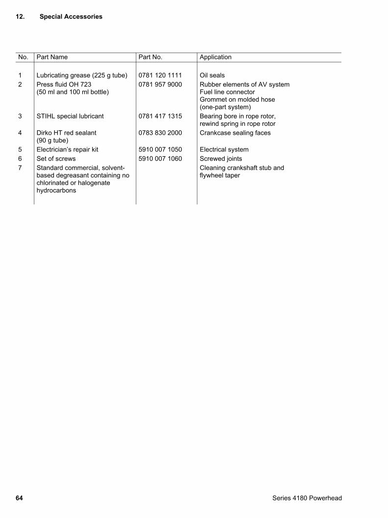
12. Special Accessories
No. Part Name Part No. Application
1 Lubricating grease (225 g tube) 0781 120 1111 Oil seals2 Press fluid OH 723
(50 ml and 100 ml bottle)0781 957 9000 Rubber elements of AV system
Fuel line connectorGrommet on molded hose (one-part system)
3 STIHL special lubricant 0781 417 1315 Bearing bore in rope rotor,rewind spring in rope rotor
4 Dirko HT red sealant (90 g tube)
0783 830 2000 Crankcase sealing faces
5 Electrician’s repair kit 5910 007 1050 Electrical system6 Set of screws 5910 007 1060 Screwed joints7 Standard commercial, solvent-
based degreasant containing no chlorinated or halogenate hydrocarbons
Cleaning crankshaft stub andflywheel taper
64 Series 4180 Powerhead

englisch / english0455 933 0123. M0,5. D6. T. Printed in Germany


![Katalog · PDF fileLh 3+ corn Lh 3+1 corn Masse* [kg] 850 1050 1020 1250 980 1200 Leistungsbedarf [PS] 90÷100 100÷110 100÷110 110÷120 90÷100 100÷110 Lichtweite unter](https://img.pdfslide.org/doc/110x75/5a787d987f8b9a8c428c42cf/katalog-a-lh-3-corn-lh-31-corn-masse-kg-850-1050-1020-1250-980-1200-leistungsbedarf.jpg)