Embed Size (px)
Citation preview
1171.6296.95–01 TI.1 E-1
Beiblatt zum Bedienhandbuch Durchgangsmesskopf R&S®NRT-Z14/-Z43/-Z44
USB-Schnittstellenadapter R&S®NRT-Z5
Inhalt
Die folgenden Seiten entsprechen Kapitel 1 des Messkopfhandbuchs R&S®NRT-Z14/-Z43/-Z44 (1171.6121.35-01). Das Kapitel enthält eine detaillierte Anleitung zum Betrieb der Messköpfe über den USB-Schnittstellenadapter R&S®NRT-Z5.
Supplement to Operating Manual R&S®NRT-Z14/-Z43/-Z44 Directional Power Sensor
R&S®NRT-Z5 USB Interface Adapter
Contents
The following pages correspond to Chapter 1 of the manual for the R&S®NRT-Z14/-Z43/-Z44 sensors (1171.6121.35-01). The chapter includes detailed instructions for operating the sensor via the R&S®NRT-Z5 USB interface adapter.
Supplément au manuel d’utilisation Tête de mesure directionnelle R&S®NRT-Z14/-Z43/-Z44
Adaptateur d’interface USB R&S®NRT-Z5
Contenu
Les pages suivantes correspondent au chapitre 1 du manuel d’utilisation de la tête de mesure R&S®NRT-Z14/-Z43/-Z44 (1171.6121.35-01). Ce chapitre présente des instructions détaillées sur le fonctionnement des têtes de mesure à l’aide de l’adaptateur d’interface USB R&S®NRT-Z5.
R&S NRT-Z43/Z44 Inbetriebnahme
1081.1309.02 1.1 D-8
1 Inbetriebnahme
VORSICHT Die Anweisungen der folgenden Abschnitte genau befolgen, damit eine Beschädigung des Geräts oder eine Gefährdung von Personen vermieden wird. Das gilt besonders für die erste Inbetriebnahme.
1.1 Auspacken
Nachdem Sie den Meßkopf aus der Verpackung genommen haben, kontrollieren Sie bitte die Vollstän-digkeit der Lieferung und überprüfen Sie alle Teile sorgfältig auf eventuelle Beschädigungen. Im Scha-densfall sollten Sie umgehend das zuständige Transportunternehmen verständigen und alle Verpa-ckungsteile zur Wahrung Ihrer Ansprüche aufbewahren. Auch für einen späteren Transport oder Ver-sand des Meßkopfes ist die Originalverpackung von Vorteil.
1.2 Meßkopf anschließen
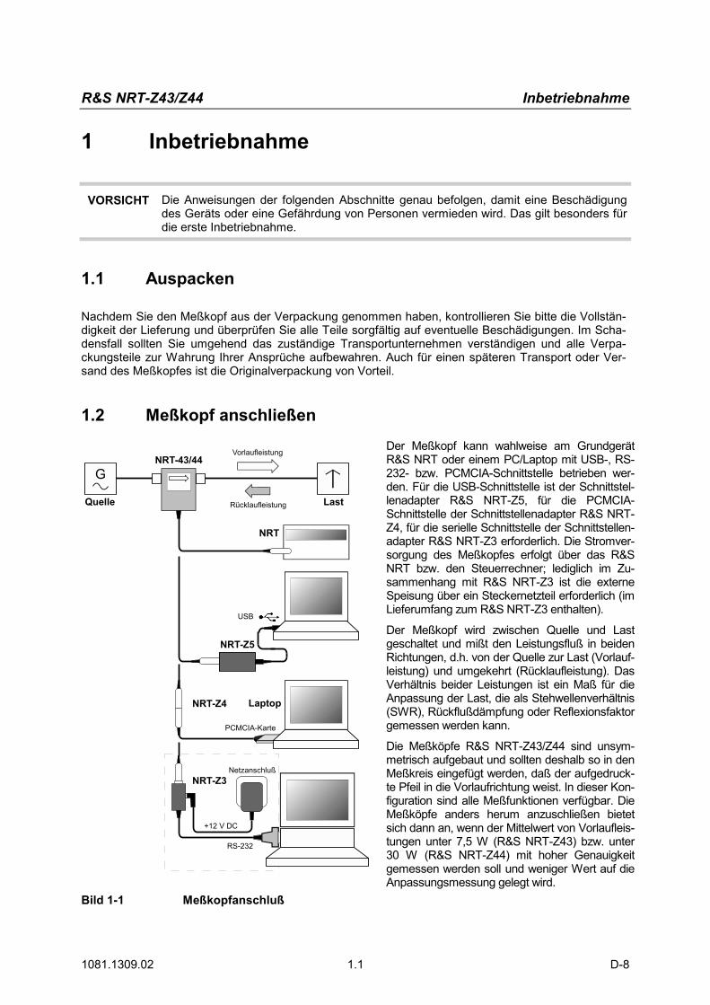
Bild 1-1 Meßkopfanschluß
Der Meßkopf kann wahlweise am Grundgerät R&S NRT oder einem PC/Laptop mit USB-, RS-232- bzw. PCMCIA-Schnittstelle betrieben wer-den. Für die USB-Schnittstelle ist der Schnittstel-lenadapter R&S NRT-Z5, für die PCMCIA-Schnittstelle der Schnittstellenadapter R&S NRT-Z4, für die serielle Schnittstelle der Schnittstellen-adapter R&S NRT-Z3 erforderlich. Die Stromver-sorgung des Meßkopfes erfolgt über das R&S NRT bzw. den Steuerrechner; lediglich im Zu-sammenhang mit R&S NRT-Z3 ist die externe Speisung über ein Steckernetzteil erforderlich (im Lieferumfang zum R&S NRT-Z3 enthalten).
Der Meßkopf wird zwischen Quelle und Last geschaltet und mißt den Leistungsfluß in beiden Richtungen, d.h. von der Quelle zur Last (Vorlauf-leistung) und umgekehrt (Rücklaufleistung). Das Verhältnis beider Leistungen ist ein Maß für die Anpassung der Last, die als Stehwellenverhältnis (SWR), Rückflußdämpfung oder Reflexionsfaktor gemessen werden kann.
Die Meßköpfe R&S NRT-Z43/Z44 sind unsym-metrisch aufgebaut und sollten deshalb so in den Meßkreis eingefügt werden, daß der aufgedruck-te Pfeil in die Vorlaufrichtung weist. In dieser Kon-figuration sind alle Meßfunktionen verfügbar. Die Meßköpfe anders herum anzuschließen bietet sich dann an, wenn der Mittelwert von Vorlaufleis-tungen unter 7,5 W (R&S NRT-Z43) bzw. unter 30 W (R&S NRT-Z44) mit hoher Genauigkeit gemessen werden soll und weniger Wert auf die Anpassungsmessung gelegt wird.
Inbetriebnahme R&S NRT-Z43/Z44
1081.1309.02 1.2 D-8
Beim Messen höherer Leistungen beachten Sie bitte unbedingt die folgenden Hinweise, um eine Be-schädigung des Meßkopfes bzw. Verletzungen zu vermeiden.
VORSICHT Max. Dauerbelastbarkeit (Diagramm auf der Rückseite) nicht überschreiten! Meßkopf nur bei abgeschalteter HF-Leistung in den Meßkreis einfügen! HF-Anschluß-Stecker handfest anziehen! Nichtbeachten kann zu Gesundheitsschäden, z.B. Verbrennungen der Haut, Beschä-digung der verwendeten Geräte und vorzeitigem Verschleiß der HF-Anschlußstecker führen!
1.3 Meßkopf an Leistungs-/Reflexionsmesser R&S NRT anschließen
SENSOR Zum Anschluß an das R&S NRT steht die Buchse SENSOR an der Frontseite oder eine der beiden Buchsen SENSOR 2 bzw. SENSOR 3 an der Geräterückseite (nur bei Option R&S NRT-B2) zur Verfügung. Einige Sekunden nach dem Anstecken bzw. Einschalten sollte das R&S NRT den Meßkopf im Rahmen einer Initialisie-rungsroutine erkennen und wenig später mit Messungen beginnen.
Die Bedienung des R&S NRT ist ausführlich im zugehörigen Betriebshandbuch be-schrieben.
1.4 Meßkopf über USB-Schnittstellenadapter R&S NRT-Z5 an einem PC betreiben
Für einen Betrieb des Meßkopfes an einem PC über den USB-Schnittstellenadapter R&S NRT-Z5 müs-sen folgende Voraussetzungen erfüllt sein:
� Der PC muß über einen USB-Anschluß verfügen, welcher einen Strom von 500 mA liefern kann. Um sicherzugehen, können Sie die an den USB-Anschlüssen verfügbare Stromstärke folgender-maßen ermitteln: • Im Windows™-Startmenü den Menüpunkt Systemsteuerung bzw. Einstellungen – Sys-
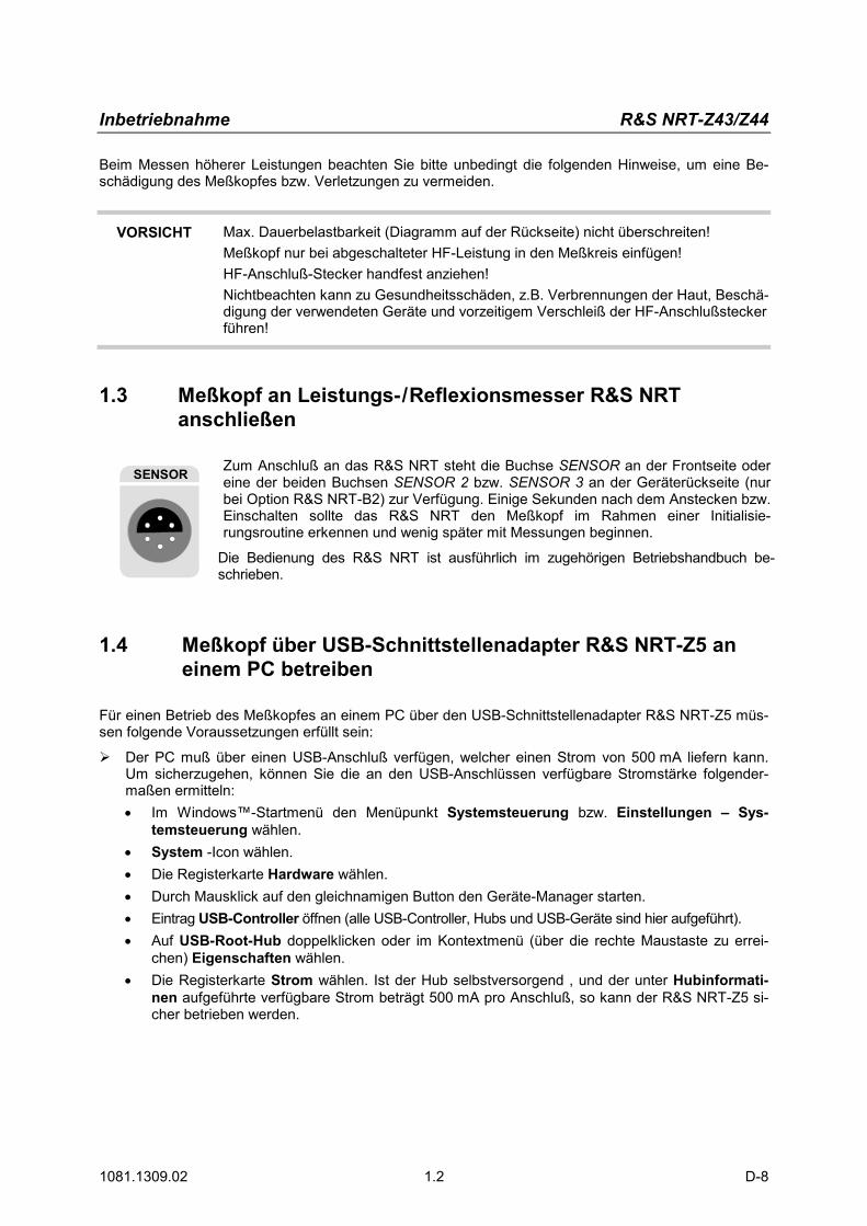
temsteuerung wählen. • System -Icon wählen. • Die Registerkarte Hardware wählen. • Durch Mausklick auf den gleichnamigen Button den Geräte-Manager starten. • Eintrag USB-Controller öffnen (alle USB-Controller, Hubs und USB-Geräte sind hier aufgeführt). • Auf USB-Root-Hub doppelklicken oder im Kontextmenü (über die rechte Maustaste zu errei-
chen) Eigenschaften wählen. • Die Registerkarte Strom wählen. Ist der Hub selbstversorgend , und der unter Hubinformati-
nen aufgeführte verfügbare Strom beträgt 500 mA pro Anschluß, so kann der R&S NRT-Z5 si-cher betrieben werden.
R&S NRT-Z43/Z44 Inbetriebnahme
1081.1309.02 1.3 D-8
� Das PC-Betriebssystem muß den USB und die Gerätetreiber für den R&S NRT-Z5 unterstützen. Dies ist der Fall für Windows™ 2000, Windows™ XP und Windows™ Vista.
1.4.1 Gerätetreiber installieren
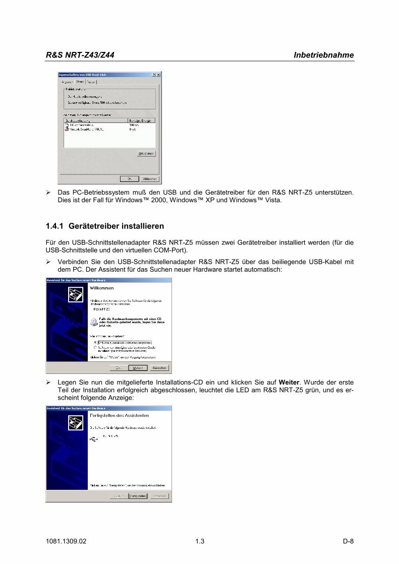
Für den USB-Schnittstellenadapter R&S NRT-Z5 müssen zwei Gerätetreiber installiert werden (für die USB-Schnittstelle und den virtuellen COM-Port). � Verbinden Sie den USB-Schnittstellenadapter R&S NRT-Z5 über das beiliegende USB-Kabel mit
dem PC. Der Assistent für das Suchen neuer Hardware startet automatisch:
� Legen Sie nun die mitgelieferte Installations-CD ein und klicken Sie auf Weiter. Wurde der erste Teil der Installation erfolgreich abgeschlossen, leuchtet die LED am R&S NRT-Z5 grün, und es er-scheint folgende Anzeige:
Inbetriebnahme R&S NRT-Z43/Z44
1081.1309.02 1.4 D-8
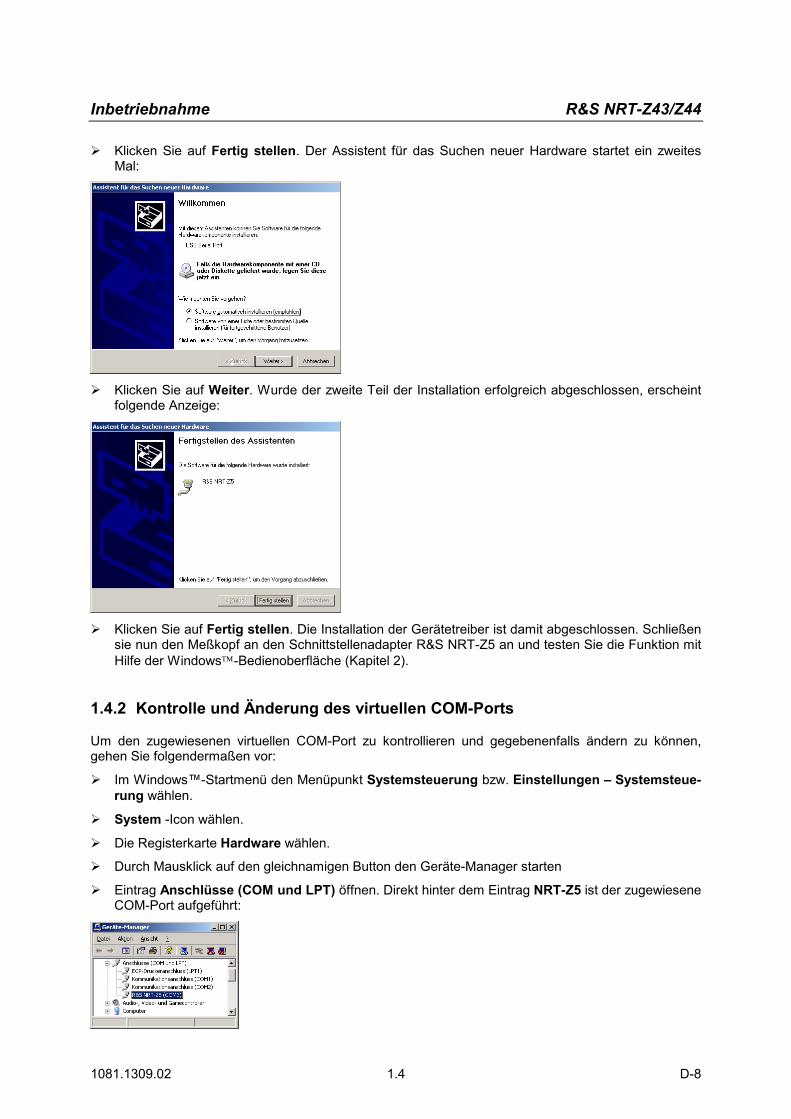
� Klicken Sie auf Fertig stellen. Der Assistent für das Suchen neuer Hardware startet ein zweites Mal:
� Klicken Sie auf Weiter. Wurde der zweite Teil der Installation erfolgreich abgeschlossen, erscheint folgende Anzeige:
� Klicken Sie auf Fertig stellen. Die Installation der Gerätetreiber ist damit abgeschlossen. Schließen sie nun den Meßkopf an den Schnittstellenadapter R&S NRT-Z5 an und testen Sie die Funktion mit Hilfe der Windows-Bedienoberfläche (Kapitel 2).
1.4.2 Kontrolle und Änderung des virtuellen COM-Ports
Um den zugewiesenen virtuellen COM-Port zu kontrollieren und gegebenenfalls ändern zu können, gehen Sie folgendermaßen vor: � Im Windows™-Startmenü den Menüpunkt Systemsteuerung bzw. Einstellungen – Systemsteue-
rung wählen.
� System -Icon wählen.
� Die Registerkarte Hardware wählen.
� Durch Mausklick auf den gleichnamigen Button den Geräte-Manager starten
� Eintrag Anschlüsse (COM und LPT) öffnen. Direkt hinter dem Eintrag NRT-Z5 ist der zugewiesene COM-Port aufgeführt:
R&S NRT-Z43/Z44 Inbetriebnahme
1081.1309.02 1.5 D-8
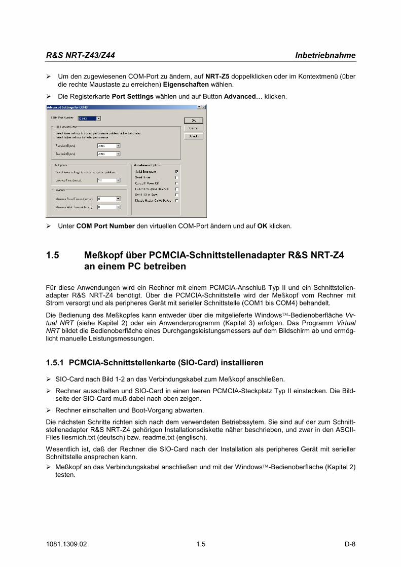
� Um den zugewiesenen COM-Port zu ändern, auf NRT-Z5 doppelklicken oder im Kontextmenü (über die rechte Maustaste zu erreichen) Eigenschaften wählen.
� Die Registerkarte Port Settings wählen und auf Button Advanced… klicken.
� Unter COM Port Number den virtuellen COM-Port ändern und auf OK klicken.
1.5 Meßkopf über PCMCIA-Schnittstellenadapter R&S NRT-Z4 an einem PC betreiben
Für diese Anwendungen wird ein Rechner mit einem PCMCIA-Anschluß Typ II und ein Schnittstellen-adapter R&S NRT-Z4 benötigt. Über die PCMCIA-Schnittstelle wird der Meßkopf vom Rechner mit Strom versorgt und als peripheres Gerät mit serieller Schnittstelle (COM1 bis COM4) behandelt.
Die Bedienung des Meßkopfes kann entweder über die mitgelieferte Windows-Bedienoberfläche Vir-tual NRT (siehe Kapitel 2) oder ein Anwenderprogramm (Kapitel 3) erfolgen. Das Programm Virtual NRT bildet die Bedienoberfläche eines Durchgangsleistungsmessers auf dem Bildschirm ab und ermög-licht manuelle Leistungsmessungen.
1.5.1 PCMCIA-Schnittstellenkarte (SIO-Card) installieren
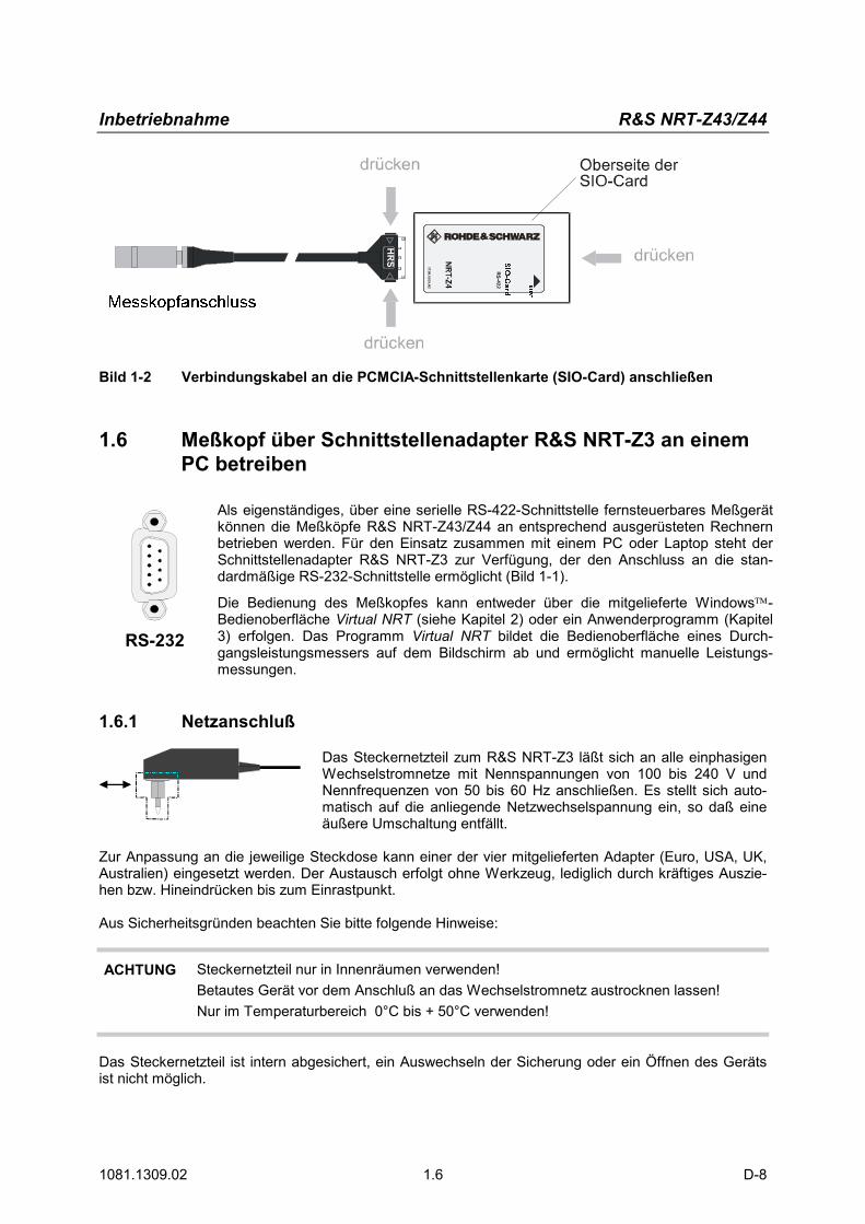
� SIO-Card nach Bild 1-2 an das Verbindungskabel zum Meßkopf anschließen.
� Rechner ausschalten und SIO-Card in einen leeren PCMCIA-Steckplatz Typ II einstecken. Die Bild-seite der SIO-Card muß dabei nach oben zeigen.
� Rechner einschalten und Boot-Vorgang abwarten.
Die nächsten Schritte richten sich nach dem verwendeten Betriebssytem. Sie sind auf der zum Schnitt-stellenadapter R&S NRT-Z4 gehörigen Installationsdiskette näher beschrieben, und zwar in den ASCII-Files liesmich.txt (deutsch) bzw. readme.txt (englisch).
Wesentlich ist, daß der Rechner die SIO-Card nach der Installation als peripheres Gerät mit serieller Schnittstelle ansprechen kann. � Meßkopf an das Verbindungskabel anschließen und mit der Windows-Bedienoberfläche (Kapitel 2)
testen.
Inbetriebnahme R&S NRT-Z43/Z44
1081.1309.02 1.6 D-8
Bild 1-2 Verbindungskabel an die PCMCIA-Schnittstellenkarte (SIO-Card) anschließen
1.6 Meßkopf über Schnittstellenadapter R&S NRT-Z3 an einem PC betreiben
RS-
232-
E
RS-232
Als eigenständiges, über eine serielle RS-422-Schnittstelle fernsteuerbares Meßgerät können die Meßköpfe R&S NRT-Z43/Z44 an entsprechend ausgerüsteten Rechnern betrieben werden. Für den Einsatz zusammen mit einem PC oder Laptop steht der Schnittstellenadapter R&S NRT-Z3 zur Verfügung, der den Anschluss an die stan-dardmäßige RS-232-Schnittstelle ermöglicht (Bild 1-1).
Die Bedienung des Meßkopfes kann entweder über die mitgelieferte Windows-Bedienoberfläche Virtual NRT (siehe Kapitel 2) oder ein Anwenderprogramm (Kapitel 3) erfolgen. Das Programm Virtual NRT bildet die Bedienoberfläche eines Durch-gangsleistungsmessers auf dem Bildschirm ab und ermöglicht manuelle Leistungs-messungen.
1.6.1 Netzanschluß
Das Steckernetzteil zum R&S NRT-Z3 läßt sich an alle einphasigen Wechselstromnetze mit Nennspannungen von 100 bis 240 V und Nennfrequenzen von 50 bis 60 Hz anschließen. Es stellt sich auto-matisch auf die anliegende Netzwechselspannung ein, so daß eine äußere Umschaltung entfällt.
Zur Anpassung an die jeweilige Steckdose kann einer der vier mitgelieferten Adapter (Euro, USA, UK, Australien) eingesetzt werden. Der Austausch erfolgt ohne Werkzeug, lediglich durch kräftiges Auszie-hen bzw. Hineindrücken bis zum Einrastpunkt. Aus Sicherheitsgründen beachten Sie bitte folgende Hinweise:
ACHTUNG Steckernetzteil nur in Innenräumen verwenden! Betautes Gerät vor dem Anschluß an das Wechselstromnetz austrocknen lassen! Nur im Temperaturbereich 0°C bis + 50°C verwenden!
Das Steckernetzteil ist intern abgesichert, ein Auswechseln der Sicherung oder ein Öffnen des Geräts ist nicht möglich.
R&S R&S NRT-Z43/Z44 Putting into Operation
1081.1309.02 1.1 E-8
1 Putting into Operation
CAUTION The following instructions should be strictly observed, in particular when putting the in-strument into operation the first time, to avoid damage to the instrument and hazards to persons.
1.1 Unpacking
After unpacking the sensor, check for completeness of the delivery and carefully check all parts for any damage. In case of any damage you should immediately inform the transport agent and keep all pack-ing material so as not to forfeit your claims. The original packing should also be used for any later transport or shipment of the sensor.
1.2 Connecting the Sensor
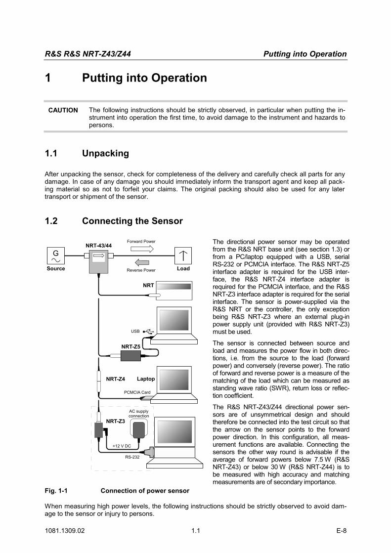
Fig. 1-1 Connection of power sensor
The directional power sensor may be operated from the R&S NRT base unit (see section 1.3) or from a PC/laptop equipped with a USB, serial RS-232 or PCMCIA interface. The R&S NRT-Z5 interface adapter is required for the USB inter-face, the R&S NRT-Z4 interface adapter is required for the PCMCIA interface, and the R&S NRT-Z3 interface adapter is required for the serial interface. The sensor is power-supplied via the R&S NRT or the controller, the only exception being R&S NRT-Z3 where an external plug-in power supply unit (provided with R&S NRT-Z3) must be used.
The sensor is connected between source and load and measures the power flow in both direc-tions, i.e. from the source to the load (forward power) and conversely (reverse power). The ratio of forward and reverse power is a measure of the matching of the load which can be measured as standing wave ratio (SWR), return loss or reflec-tion coefficient.
The R&S NRT-Z43/Z44 directional power sen-sors are of unsymmetrical design and should therefore be connected into the test circuit so that the arrow on the sensor points to the forward power direction. In this configuration, all meas-urement functions are available. Connecting the sensors the other way round is advisable if the average of forward powers below 7.5 W (R&S NRT-Z43) or below 30 W (R&S NRT-Z44) is to be measured with high accuracy and matching measurements are of secondary importance.
When measuring high power levels, the following instructions should be strictly observed to avoid dam-age to the sensor or injury to persons.
Putting into Operation R&S NRT-Z43/Z44
1081.1309.02 1.2 E-8
CAUTION Do not exceed permissible continuous loading (see diagram on the rear). Switch sensor into test circuit only with the RF power switched off. Tighten RF connector by hand. Non-observance may cause injuries, i.e. skin burns, damage to the instruments used and premature wear of the RF connectors.
1.3 Connecting the Sensor to the R&S NRT Power Reflection Meter
SENSORThe sensor can be connected to the SENSOR connector on the front panel of the R&S NRT or to the SENSOR 2 or SENSOR 3 connector on the rear panel (only with option R&S NRT-B2). The R&S NRT should recognize the sensor in an initialization routine a few seconds after the connection is made or after power-up, respectively, and immediately start measurements.
Operation of the R&S NRT is described in detail in the associated operating manual.
1.4 Operating the Sensor on a PC via the R&S NRT-Z5USB Interface Adapter
To operate the sensor on a PC via the R&S NRT-Z5 USB interface adapter, the following requirements must be met:
� The PC must have a USB port that can supply current of 500 mA. To be on the safe side, you can determine the current available on the USB ports as follows:
• Select Control Panel or Settings – Control Panel in the Windows™ start menu
• Select the System icon
• Select the Hardware tab
• Click the Device Manager button to start the device manager
• Open the Universal Serial Bus controllers item (listing all USB controllers, hubs and USB de-vices)
• Double-click USB Root Hub (or right-click and select Properties in the context menu)
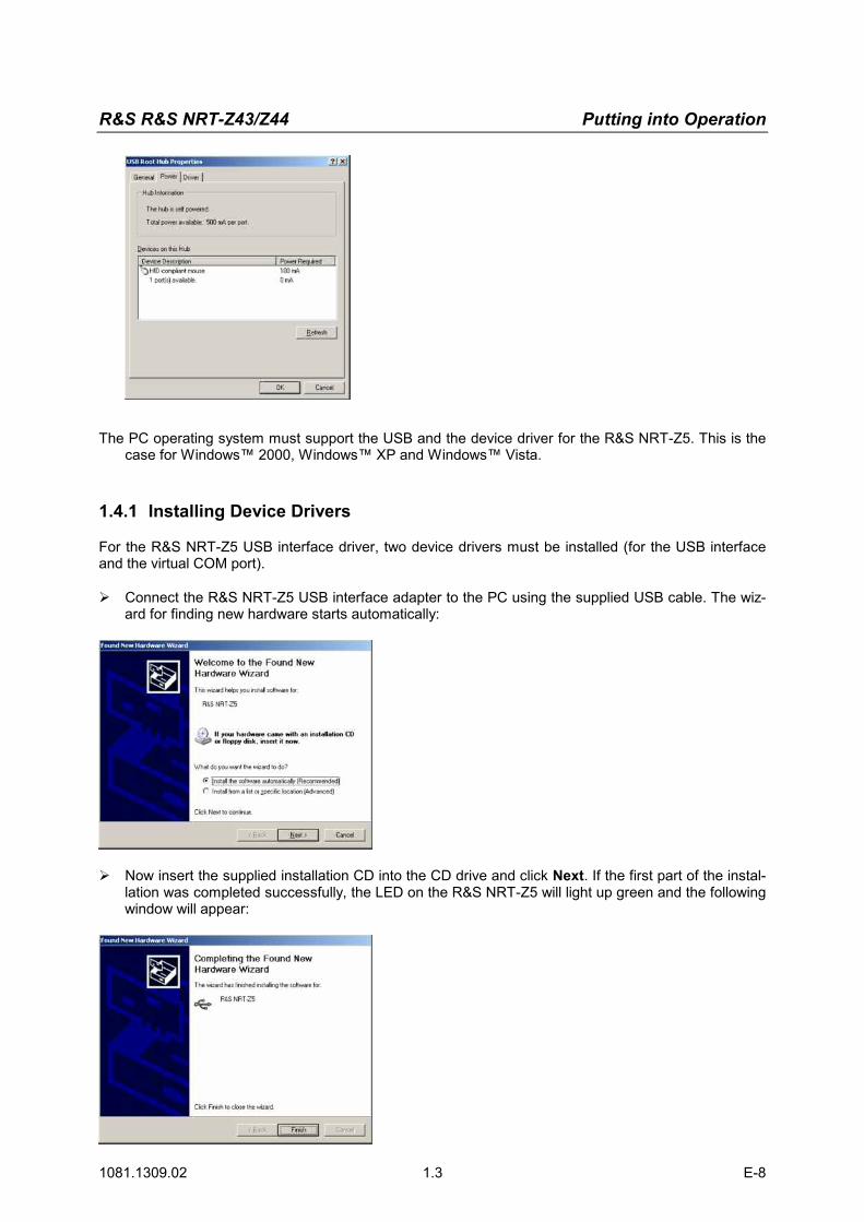
• Select the Power tab: If the hub is self-powered and the total power available indicated under Hub information is 500 mA per port, the R&S NRT-Z5 can be safely operated.
R&S R&S NRT-Z43/Z44 Putting into Operation
1081.1309.02 1.3 E-8
The PC operating system must support the USB and the device driver for the R&S NRT-Z5. This is the case for Windows™ 2000, Windows™ XP and Windows™ Vista.
1.4.1 Installing Device Drivers
For the R&S NRT-Z5 USB interface driver, two device drivers must be installed (for the USB interface and the virtual COM port). � Connect the R&S NRT-Z5 USB interface adapter to the PC using the supplied USB cable. The wiz-
ard for finding new hardware starts automatically:
� Now insert the supplied installation CD into the CD drive and click Next. If the first part of the instal-lation was completed successfully, the LED on the R&S NRT-Z5 will light up green and the following window will appear:
Putting into Operation R&S NRT-Z43/Z44
1081.1309.02 1.4 E-8
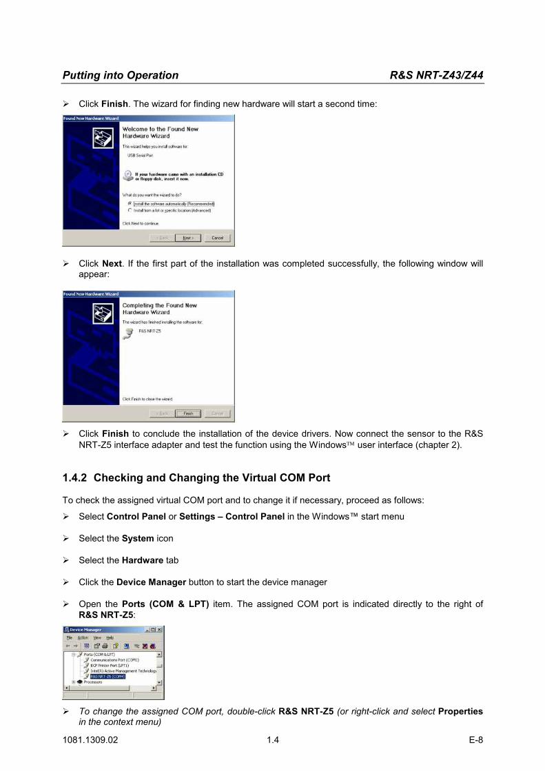
� Click Finish. The wizard for finding new hardware will start a second time:
� Click Next. If the first part of the installation was completed successfully, the following window will appear:
� Click Finish to conclude the installation of the device drivers. Now connect the sensor to the R&S NRT-Z5 interface adapter and test the function using the Windows user interface (chapter 2).
1.4.2 Checking and Changing the Virtual COM Port
To check the assigned virtual COM port and to change it if necessary, proceed as follows:
� Select Control Panel or Settings – Control Panel in the Windows™ start menu
� Select the System icon
� Select the Hardware tab
� Click the Device Manager button to start the device manager
� Open the Ports (COM & LPT) item. The assigned COM port is indicated directly to the right of R&S NRT-Z5:
� To change the assigned COM port, double-click R&S NRT-Z5 (or right-click and select Properties in the context menu)
R&S R&S NRT-Z43/Z44 Putting into Operation
1081.1309.02 1.5 E-8
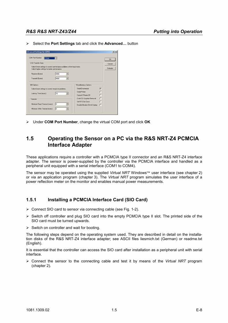
� Select the Port Settings tab and click the Advanced… button
� Under COM Port Number, change the virtual COM port and click OK
1.5 Operating the Sensor on a PC via the R&S NRT-Z4 PCMCIA Interface Adapter
These applications require a controller with a PCMCIA type II connector and an R&S NRT-Z4 interface adapter. The sensor is power-supplied by the controller via the PCMCIA interface and handled as a peripheral unit equipped with a serial interface (COM1 to COM4).
The sensor may be operated using the supplied Virtual NRT Windows user interface (see chapter 2) or via an application program (chapter 3). The Virtual NRT program simulates the user interface of a power reflection meter on the monitor and enables manual power measurements.
1.5.1 Installing a PCMCIA Interface Card (SIO Card)
� Connect SIO card to sensor via connecting cable (see Fig. 1-2).
� Switch off controller and plug SIO card into the empty PCMCIA type II slot. The printed side of the SIO card must be turned upwards.
� Switch on controller and wait for booting.
The following steps depend on the operating system used. They are described in detail on the installa-tion disks of the R&S NRT-Z4 interface adapter; see ASCII files liesmich.txt (German) or readme.txt (English).
It is essential that the controller can access the SIO card after installation as a peripheral unit with serial interface.
� Connect the sensor to the connecting cable and test it by means of the Virtual NRT program (chapter 2).
Putting into Operation R&S NRT-Z43/Z44
1081.1309.02 1.6 E-8
SIO-C
ard
NR
T-Z4
RS-422
1120.5005.02
INS
ER
T
HR
S
press
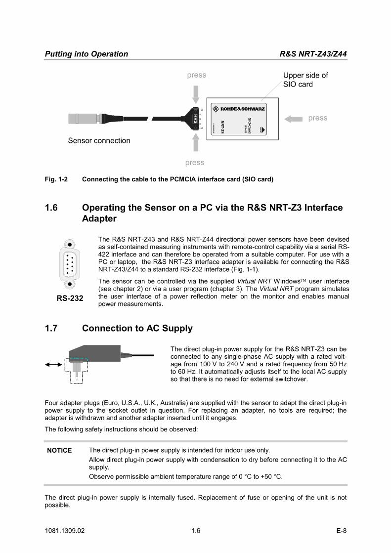
Sensor connection
Upper side ofSIO card
press
press
Fig. 1-2 Connecting the cable to the PCMCIA interface card (SIO card)
1.6 Operating the Sensor on a PC via the R&S NRT-Z3 Interface Adapter
RS-
232-
E
RS-232
The R&S NRT-Z43 and R&S NRT-Z44 directional power sensors have been devised as self-contained measuring instruments with remote-control capability via a serial RS-422 interface and can therefore be operated from a suitable computer. For use with a PC or laptop, the R&S NRT-Z3 interface adapter is available for connecting the R&S NRT-Z43/Z44 to a standard RS-232 interface (Fig. 1-1).
The sensor can be controlled via the supplied Virtual NRT Windows user interface (see chapter 2) or via a user program (chapter 3). The Virtual NRT program simulates the user interface of a power reflection meter on the monitor and enables manual power measurements.
1.7 Connection to AC Supply
The direct plug-in power supply for the R&S NRT-Z3 can be connected to any single-phase AC supply with a rated volt-age from 100 V to 240 V and a rated frequency from 50 Hz to 60 Hz. It automatically adjusts itself to the local AC supply so that there is no need for external switchover.
Four adapter plugs (Euro, U.S.A., U.K., Australia) are supplied with the sensor to adapt the direct plug-in power supply to the socket outlet in question. For replacing an adapter, no tools are required; the adapter is withdrawn and another adapter inserted until it engages.
The following safety instructions should be observed:
NOTICE The direct plug-in power supply is intended for indoor use only. Allow direct plug-in power supply with condensation to dry before connecting it to the AC supply. Observe permissible ambient temperature range of 0 °C to +50 °C.
The direct plug-in power supply is internally fused. Replacement of fuse or opening of the unit is not possible.
NRT-Z14/Z43/Z44 Mise en service
1081.1309.02 1.1 F-7
1 Mise en service
ATTENTION Respecter minutieusement les instructions des paragraphes suivants pour éviter tout endommagement de l’appareil ou tout risque à l'égard de personnes, surtout s'il s'agit de la première mise en circuit.
1.1 Déballage
Après avoir retiré la tête de mesure hors de son emballage, contrôler le lot dans son intégralité et vérifier soigneusement chaque pièce pour détecter de dommages éventuels. Le cas échéant, avertir au plus vite l’entreprise responsable du transport et conserver le matériel d’emballage afin de corroborer vos déclarations. L’emballage d’origine permet ultérieurement le transport ou l’envoi d’une nouvelle tête de mesure.
1.2 Connexion de la tête de mesure
G
Source Charge
NRT
NRT-Z14/- Z43/-Z44 Puissance directe
Puissance réfléchie
RS - 232
Rechner
+ 12 V DC
ConnConnecteur secteurNRT- Z3
Rechner
PortableNRT- Z4
Carte PCMCIA
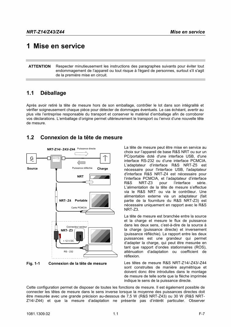
Fig. 1-1 Connexion de la tête de mesure
La tête de mesure peut être mise en service au choix sur l’appareil de base R&S NRT ou sur un PC/portable doté d'une interface USB, d'une interface RS-232 ou d’une interface PCMCIA. L’adaptateur d’interface R&S NRT-Z5 est nécessaire pour l'interface USB, l'adaptateur d'interface R&S NRT-Z4 est nécessaire pour l’interface PCMCIA, et l’adaptateur d’interface R&S NRT-Z3 pour l’interface série. L’alimentation de la tête de mesure s’effectue via le R&S NRT ou via le contrôleur. Une alimentation externe via un adaptateur (fait partie de la fourniture du R&S NRT-Z3) est nécessaire uniquement en rapport avec le R&S NRT-Z3.
La tête de mesure est branchée entre la source et la charge et mesure le flux de puissance dans les deux sens, c’est-à-dire de la source à la charge (puissance directe) et inversement (puissance réfléchie). Le rapport entre les deux puissances est une grandeur qui permet d’adapter la charge, qui peut être mesurée en tant que rapport d’ondes stationnaires (ROS), atténuation d’adaptation ou coefficient de réflexion.
Les têtes de mesure R&S NRT-Z14/-Z43/-Z44 sont construites de manière asymétrique et doivent donc être introduites dans le montage de mesure de telle sorte que la flèche imprimée indique le sens de la puissance directe.
Cette configuration permet de disposer de toutes les fonctions de mesure. Il est également possible de connecter les têtes de mesure dans le sens inverse lorsque la moyenne des puissances directes doit être mesurée avec une grande précision au-dessous de 7,5 W (R&S NRT-Z43) ou 30 W (R&S NRT-Z14/-Z44) et que la mesure d’adaptation ne présente pas d’intérêt particulier. Observer
Mise en service NRT-Z14/Z43/-Z44
1081.1309.02 1.2 F-7
scrupuleusement les instructions suivantes lors de la mesure de puissances plus élevées, afin d’éviter d’endommager les têtes de mesure ou de subir des blessures.
ATTENTION
Ne pas dépasser la charge admissible permanente (voir diagramme sur la face arrière). N’insérer la tête de mesure que si la puissance RF est hors circuit. Brancher manuellement le connecteur RF! Le non-respect de ces instructions peut entraîner des blessures telles que des brûlures, une détérioration des appareils utilisés et une usure précoce des connecteurs RF.
1.3 Raccordement de la tête de mesure au wattmètre/ réflectomètre R&S NRT
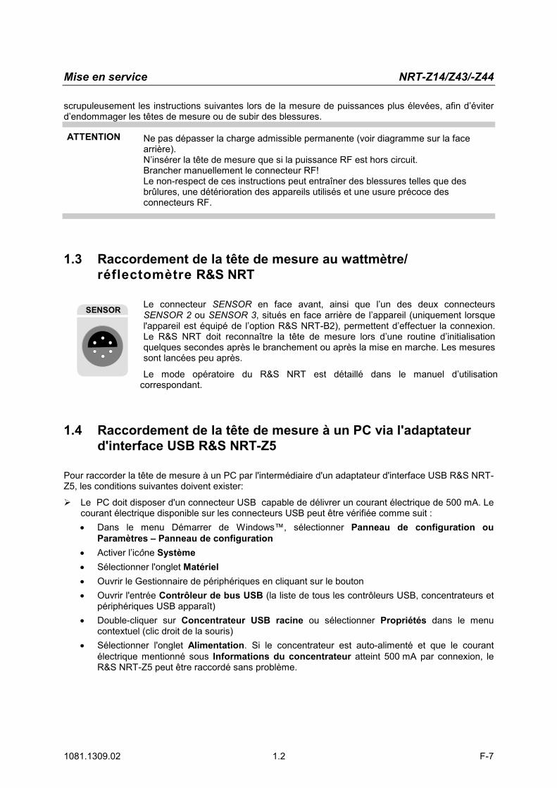
SENSOR Le connecteur SENSOR en face avant, ainsi que l’un des deux connecteurs SENSOR 2 ou SENSOR 3, situés en face arrière de l’appareil (uniquement lorsque l'appareil est équipé de l’option R&S NRT-B2), permettent d’effectuer la connexion. Le R&S NRT doit reconnaître la tête de mesure lors d’une routine d’initialisation quelques secondes après le branchement ou après la mise en marche. Les mesures sont lancées peu après.
Le mode opératoire du R&S NRT est détaillé dans le manuel d’utilisation correspondant.
1.4 Raccordement de la tête de mesure à un PC via l'adaptateur d'interface USB R&S NRT-Z5
Pour raccorder la tête de mesure à un PC par l'intermédiaire d'un adaptateur d'interface USB R&S NRT-Z5, les conditions suivantes doivent exister:
� Le PC doit disposer d'un connecteur USB capable de délivrer un courant électrique de 500 mA. Le courant électrique disponible sur les connecteurs USB peut être vérifiée comme suit : • Dans le menu Démarrer de Windows™, sélectionner Panneau de configuration ou
Paramètres – Panneau de configuration • Activer l’icône Système • Sélectionner l'onglet Matériel • Ouvrir le Gestionnaire de périphériques en cliquant sur le bouton • Ouvrir l'entrée Contrôleur de bus USB (la liste de tous les contrôleurs USB, concentrateurs et
périphériques USB apparaît) • Double-cliquer sur Concentrateur USB racine ou sélectionner Propriétés dans le menu
contextuel (clic droit de la souris) • Sélectionner l'onglet Alimentation. Si le concentrateur est auto-alimenté et que le courant
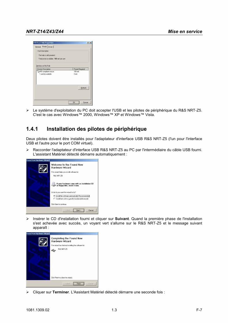
électrique mentionné sous Informations du concentrateur atteint 500 mA par connexion, le R&S NRT-Z5 peut être raccordé sans problème.
NRT-Z14/Z43/Z44 Mise en service
1081.1309.02 1.3 F-7
� Le système d'exploitation du PC doit accepter l'USB et les pilotes de périphérique du R&S NRT-Z5. C'est le cas avec Windows™ 2000, Windows™ XP et Windows™ Vista.
1.4.1 Installation des pilotes de périphérique
Deux pilotes doivent être installés pour l'adaptateur d'interface USB R&S NRT-Z5 (l'un pour l'interface USB et l'autre pour le port COM virtuel). � Raccorder l'adaptateur d'interface USB R&S NRT-Z5 au PC par l'intermédiaire du câble USB fourni.
L'assistant Matériel détecté démarre automatiquement :
� Insérer le CD d'installation fourni et cliquer sur Suivant. Quand la première phase de l'installation s'est achevée avec succès, un voyant vert s'allume sur le R&S NRT-Z5 et le message suivant apparaît :
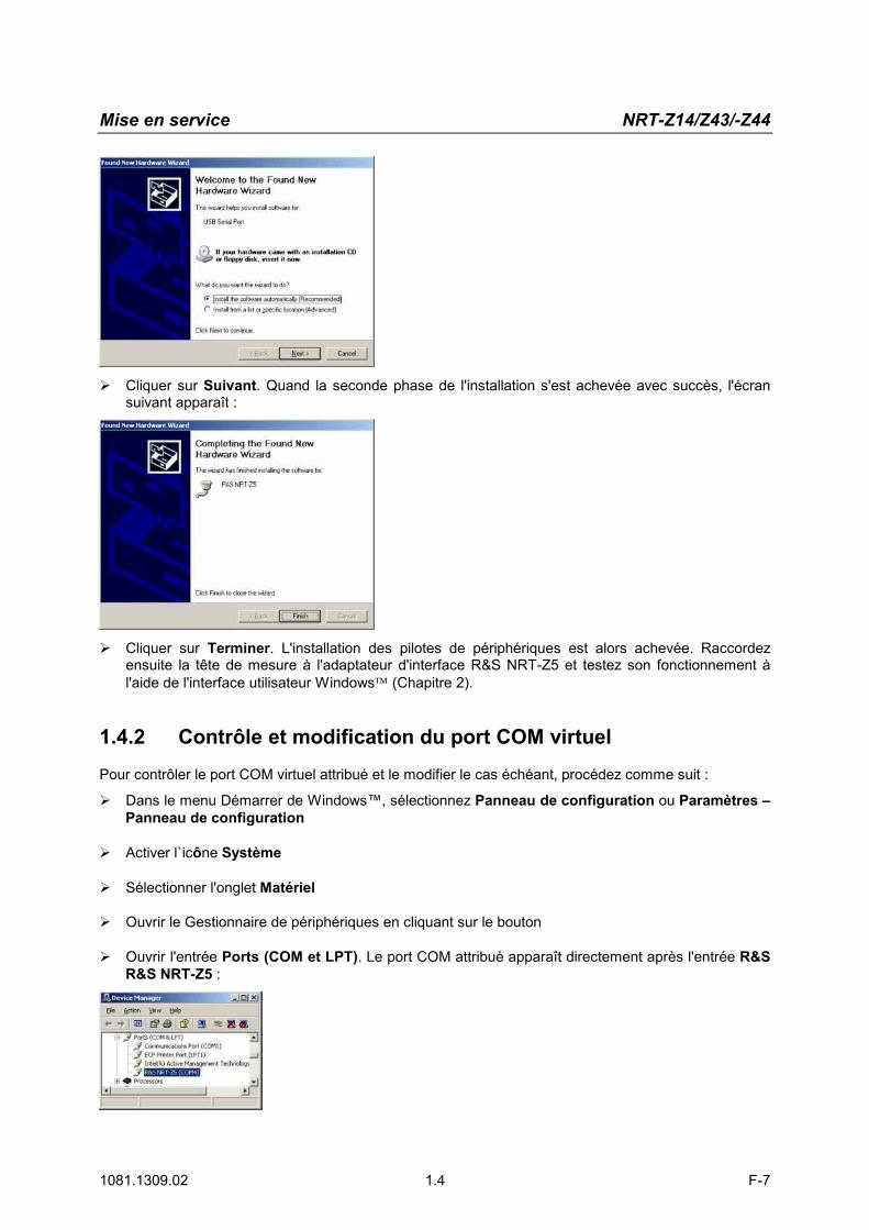
� Cliquer sur Terminer. L'Assistant Matériel détecté démarre une seconde fois :
Mise en service NRT-Z14/Z43/-Z44
1081.1309.02 1.4 F-7
� Cliquer sur Suivant. Quand la seconde phase de l'installation s'est achevée avec succès, l'écran suivant apparaît :
� Cliquer sur Terminer. L'installation des pilotes de périphériques est alors achevée. Raccordez ensuite la tête de mesure à l'adaptateur d'interface R&S NRT-Z5 et testez son fonctionnement à l'aide de l'interface utilisateur Windows (Chapitre 2).
1.4.2 Contrôle et modification du port COM virtuel
Pour contrôler le port COM virtuel attribué et le modifier le cas échéant, procédez comme suit :
� Dans le menu Démarrer de Windows™, sélectionnez Panneau de configuration ou Paramètres – Panneau de configuration
� Activer l`icône Système
� Sélectionner l'onglet Matériel
� Ouvrir le Gestionnaire de périphériques en cliquant sur le bouton
� Ouvrir l'entrée Ports (COM et LPT). Le port COM attribué apparaît directement après l'entrée R&S R&S NRT-Z5 :
NRT-Z14/Z43/Z44 Mise en service
1081.1309.02 1.5 F-7
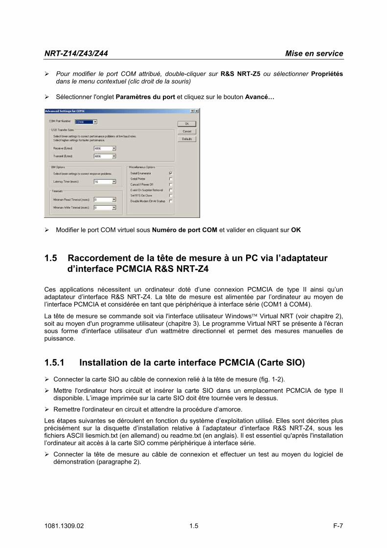
� Pour modifier le port COM attribué, double-cliquer sur R&S NRT-Z5 ou sélectionner Propriétés dans le menu contextuel (clic droit de la souris)
� Sélectionner l'onglet Paramètres du port et cliquez sur le bouton Avancé…
� Modifier le port COM virtuel sous Numéro de port COM et valider en cliquant sur OK
1.5 Raccordement de la tête de mesure à un PC via l’adaptateur d’interface PCMCIA R&S NRT-Z4
Ces applications nécessitent un ordinateur doté d’une connexion PCMCIA de type II ainsi qu’un adaptateur d’interface R&S NRT-Z4. La tête de mesure est alimentée par l’ordinateur au moyen de l’interface PCMCIA et considérée en tant que périphérique à interface série (COM1 à COM4).
La tête de mesure se commande soit via l'interface utilisateur Windows Virtual NRT (voir chapitre 2), soit au moyen d'un programme utilisateur (chapitre 3). Le programme Virtual NRT se présente à l'écran sous forme d'interface utilisateur d'un wattmètre directionnel et permet des mesures manuelles de puissance.
1.5.1 Installation de la carte interface PCMCIA (Carte SIO)
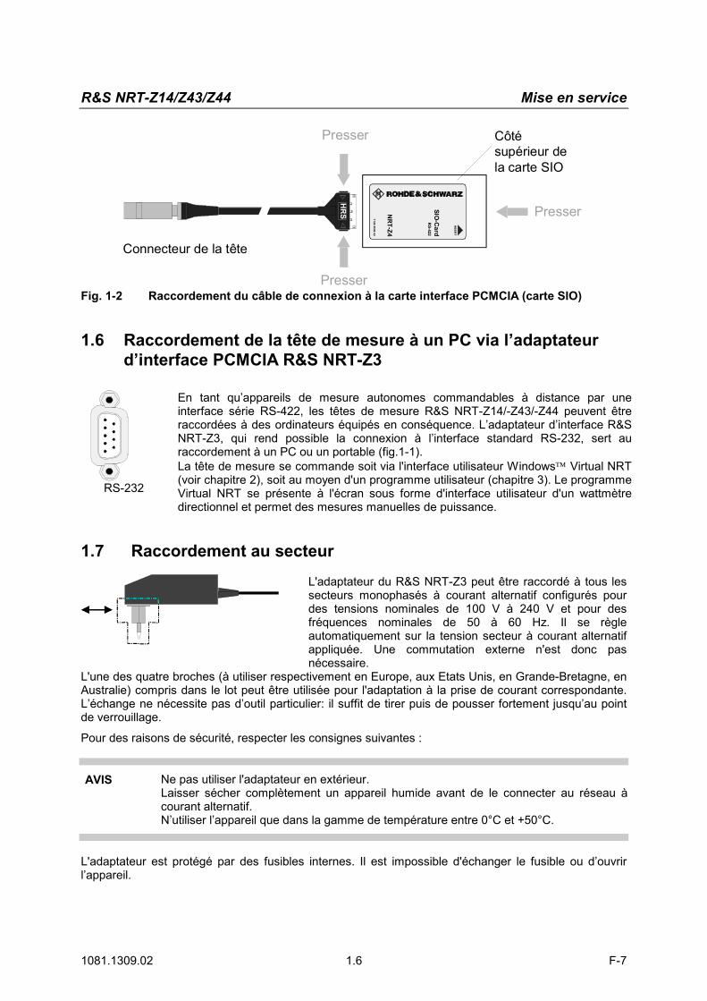
� Connecter la carte SIO au câble de connexion relié à la tête de mesure (fig. 1-2).
� Mettre l'ordinateur hors circuit et insérer la carte SIO dans un emplacement PCMCIA de type II disponible. L’image imprimée sur la carte SIO doit être tournée vers le dessus.
� Remettre l'ordinateur en circuit et attendre la procédure d’amorce.
Les étapes suivantes se déroulent en fonction du système d’exploitation utilisé. Elles sont décrites plus précisément sur la disquette d’installation relative à l’adaptateur d’interface R&S NRT-Z4, sous les fichiers ASCII liesmich.txt (en allemand) ou readme.txt (en anglais). Il est essentiel qu'après l'installation l’ordinateur ait accès à la carte SIO comme périphérique à interface série.
� Connecter la tête de mesure au câble de connexion et effectuer un test au moyen du logiciel de démonstration (paragraphe 2).
R&S NRT-Z14/Z43/Z44 Mise en service
1081.1309.02 1.6 F-7
SIO-C
ard
NR
T-Z4
RS-422
1120.5005.02
INSER
T
HR
S
Presser
Connecteur de la tête
Côtésupérieur dela carte SIO
Presser
Presser
Fig. 1-2 Raccordement du câble de connexion à la carte interface PCMCIA (carte SIO)
1.6 Raccordement de la tête de mesure à un PC via l’adaptateurd’interface PCMCIA R&S NRT-Z3
RS-
232-
E
RS-232
En tant qu’appareils de mesure autonomes commandables à distance par une interface série RS-422, les têtes de mesure R&S NRT-Z14/-Z43/-Z44 peuvent être raccordées à des ordinateurs équipés en conséquence. L’adaptateur d’interface R&S NRT-Z3, qui rend possible la connexion à l’interface standard RS-232, sert au raccordement à un PC ou un portable (fig.1-1). La tête de mesure se commande soit via l'interface utilisateur Windows Virtual NRT (voir chapitre 2), soit au moyen d'un programme utilisateur (chapitre 3). Le programme Virtual NRT se présente à l'écran sous forme d'interface utilisateur d'un wattmètre directionnel et permet des mesures manuelles de puissance.
1.7 Raccordement au secteur
L'adaptateur du R&S NRT-Z3 peut être raccordé à tous les secteurs monophasés à courant alternatif configurés pour des tensions nominales de 100 V à 240 V et pour des fréquences nominales de 50 à 60 Hz. Il se règle automatiquement sur la tension secteur à courant alternatif appliquée. Une commutation externe n'est donc pas nécessaire.
L'une des quatre broches (à utiliser respectivement en Europe, aux Etats Unis, en Grande-Bretagne, en Australie) compris dans le lot peut être utilisée pour l'adaptation à la prise de courant correspondante. L’échange ne nécessite pas d’outil particulier: il suffit de tirer puis de pousser fortement jusqu’au point de verrouillage. Pour des raisons de sécurité, respecter les consignes suivantes :
AVIS Ne pas utiliser l'adaptateur en extérieur. Laisser sécher complètement un appareil humide avant de le connecter au réseau à courant alternatif. N’utiliser l’appareil que dans la gamme de température entre 0°C et +50°C.
L'adaptateur est protégé par des fusibles internes. Il est impossible d'échanger le fusible ou d’ouvrir l’appareil.