Embed Size (px)
Citation preview
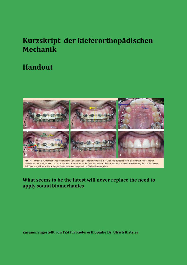
Kurzskript der kieferorthopädischen Mechanik Handout
What seems to be the latest will never replace the need to apply sound biomechanics Zusammengestellt von FZA für Kieferorthopädie Dr. Ulrich Kritzler
ßig kreissegmentförmig gebogen wird, überträgt er eine vertikalgerichtete Kraft auf die Einheit, mit der er punktförmig Kontakthat. Demgegenüber wird ein logarithmisch gebogener Drahteine Kraft übertragen, die zu einer geringen Kontraktion undzur Verkürzung des Zahnbogens führt. Wird der Teilbogen aus 2unterschiedlich starken Drähten kombiniert, wobei der dickereposterior und der dünnere anterior liegt, ändert sich die Achsen-richtung. Das Zentrum befindet sich nun an der Stelle, an der derdünnere Draht angesetzt wurde und ein beträchtlicher Teil derKraft wirkt nun horizontal, was zu einer Retraktion und Intrusionder Zähne führt [9]. Wird in einem ersten Schritt der Behandlungeine Protrusion durchgeführt und ist zu einem späteren Zeit-punkt eine Retraktion geplant, müssen die Gewebe 2-mal in ent-
gegengesetzter Richtung reagieren, was schädlich sein kann undZeit erfordert.
Zwei-Vektoren-Mechanik!
Verläuft der gewünschte Kraftvektor abseitig und lässt sich nichtdurch einen einfachen Segmentbogen generieren, kann die Lö-sung in der Verwendung von 2Teilbögen liegen [15].Das Design dieser Art vonMechanik beruht auf einfachenmathe-matischen Grundlagen und kann auch mit der Software durch-geführt werden, die auf der CD zur Biomechanik enthalten ist,die von Fiorelli u.Melsen [6] entwickelt wurde.
a b
d e f
c
Abb.16 Intraorale Aufnahmen eines Patienten mit Verschiebung der oberen Mittellinie. a–c Die Korrektur sollte durch eine Translation der oberen4Schneidezähne erfolgen. Der dazu erforderliche Kraftvektor ist auf der frontalen und der Okklusalaufnahme markiert. d Markierung der von den beidenTeilbögen ausgeübten Kräfte, e fortgeschrittenes Behandlungsstadium, f Behandlungsergebnis.
ca b
d e f
Abb.17 a–g Patient mit einem einzelnen extrem vorstehenden Schneidezahn. Die Röntgenaufnahme zeigt den massiven Knochenabbau. Der Kraftvektor,der zur Retraktion und Intrusion des Zahnes erforderlich war, wurde durch Ausüben einer waagerechten Retraktions- und einer senkrechten Intrusionskraft aufdas Bracket erzeugt.
Originalarbeit
95
Melsen B, Fiorelli G. Wer braucht heute noch Biomechanik? Inf Orthod Kieferorthop 2010; 42: 87–96
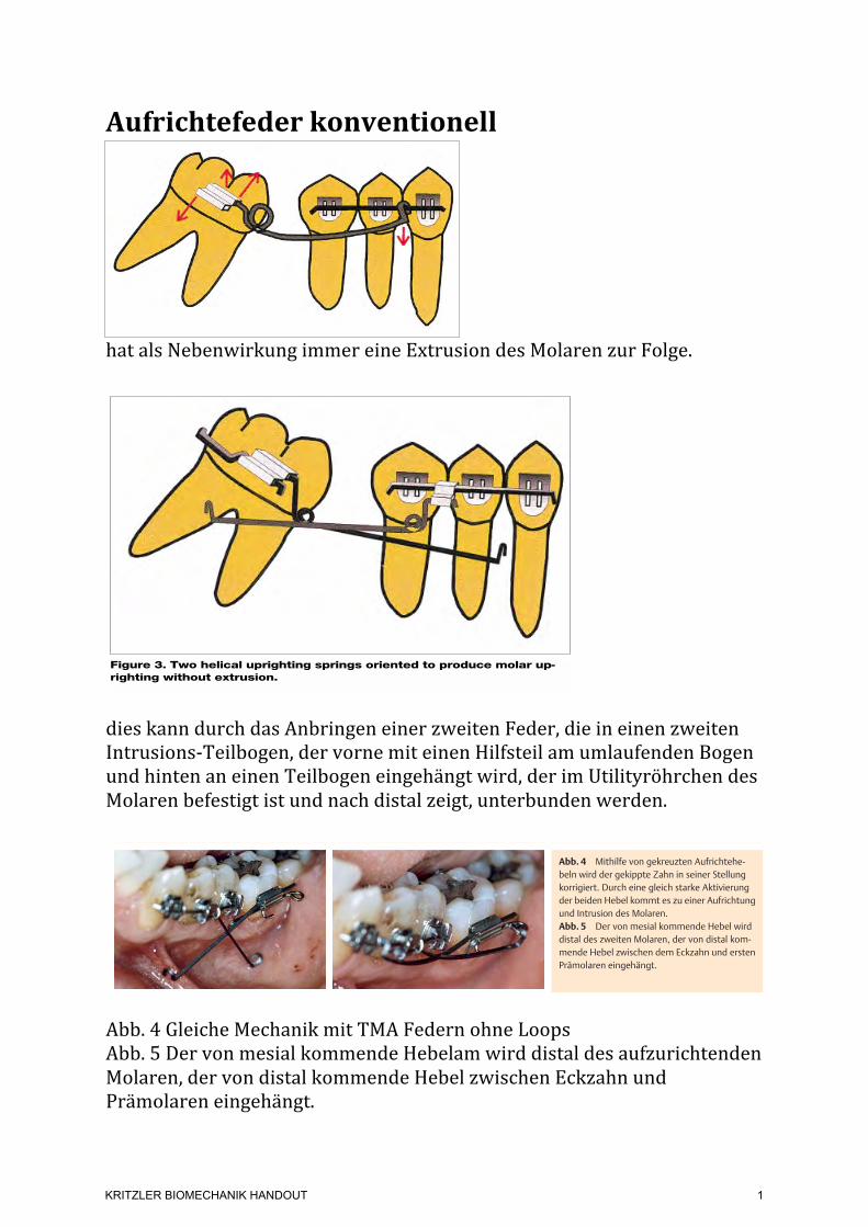
Aufrichtefeder konventionell
hat als Nebenwirkung immer eine Extrusion des Molaren zur Folge.
dies kann durch das Anbringen einer zweiten Feder, die in einen zweiten Intrusions-‐Teilbogen, der vorne mit einen Hilfsteil am umlaufenden Bogen und hinten an einen Teilbogen eingehängt wird, der im Utilityröhrchen des Molaren befestigt ist und nach distal zeigt, unterbunden werden.
Abb. 4 Gleiche Mechanik mit TMA Federn ohne Loops Abb. 5 Der von mesial kommende Hebelam wird distal des aufzurichtenden Molaren, der von distal kommende Hebel zwischen Eckzahn und Prämolaren eingehängt.
MOLAR UPRIGHTINGWITH THE HELICALUPRIGHTING SPRING
The helical uprighting spring(Figure 1), like many orthodon-tic appliances, uses an elastical-ly deformed wire to exert forceson the teeth. With this appli-ance, the active wire is insertedinto the bracket that is affixedto the tipped molar. Usually,this active wire is relativelylarge and rectangular so thereis not a lot of room for the wireto rotate or otherwise movewithin the bracket slot. Ofcourse, if the wire were smallenough to rotate within thebracket, the wire could revolveto a position from which itwould produce altered direc-tions of force, and undesirabletooth movement could occur.
Choice of wire. If thebracket slot size is 18 mil (.018inch), a good choice for the wireis 16- × 22-mil stainless steel. Alarge wire like this is not inher-ently springy, and springinessis desirable when teeth are tobe moved. A springy wire is eas-ier to activate with the preciseamount of force, and the force itexerts is of longer duration thanthat of a stiff wire (tooth move-ment does not change the levelof force nearly as much for aspringy wire as it does for a stiffwire).8 To make the wirespringier, the dentist increasesthe length of the wire that willdeform elastically (that is, thelength between brackets), bothby skipping a couple of teethand by incorporating a helicalcoil (Figure 1).
An alternative to the 16- ×22-mil stainless steel wire witha helix is a 17- × 25-mil titani-um-molybdenum alloy, or TMA,wire. Because it is inherentlymore springy than stainlesssteel, this wire often can be
used without a helix. A hook isformed at one end of thespringy wire (either the stain-less steel wire or the TMAwire), and the hook attaches themesial end of the spring to alarge, stiff wire that is rigidlyattached to a number of anteri-or teeth. The purpose of this
large, stiff wire is to anchorthese anterior teeth together sothat none of them can movemuch without all of the teethmoving. A good choice of wiresize and material for this an-choring wire is 17- × 25-milstainless steel (for an 18-mil–sized slot). The strategy ofattaching a stiff wire to a num-ber of teeth is usually effectivein reducing the movement ofthese teeth.9
Determining forces. One of
the easiest and most reliableways to determine all of theforces that an appliance willexert on the teeth is to deter-mine all of the forces that areneeded to activate or elasticallydeform the appliance. To de-form the spring, a balanced setof forces must be placed on it. Ifthe forces are not balanced, thewire will not deform, but willmove to a new position. Todemonstrate the balanced na-ture of the forces that are need-ed to deform this spring, we willdescribe the forces that act onthe wire, starting with the mostobvious and moving to the leastobvious.
The most obvious force thatacts on this wire after it hasbeen placed in the molar brack-et is the occlusally directedforce that lifts the hook so thatit can be placed over the stiffanterior wire (Figure 1, forceA). However, if this were theonly force acting on the wire,the wire would not deform. Itwould simply move in an oc-clusal direction. The molarbracket holds the wire andkeeps it from moving occlusallyby exerting an apically directedforce on it (Figure 1, force B).Yet, if these two forces were the
JADA, Vol. 130, March 1999 383
CLINICAL PRACTICE
Figure 2. Forces on the teeth from the elastically deformed wire areshown.
Opening the anterioroverbite could beadvantageous, butoften can be disas-trous, especially ifcomprehensive or-thodontic treatmentis not planned.
Copyright ©1998-2001 American Dental Association. All rights reserved.
only ones that acted on thewire, it would still not deformelastically, but would simply ro-tate (this rotation would becounterclockwise in Figure 1).
Once again, the molar brack-et holds the wire, and keeps itfrom spinning by placing a setof forces on it. As the wire be-gins to rotate in a counterclock-wise direction, as describedabove, it encounters the mesialand distal aspects of the molarbracket slot. The mesial aspectof the bracket slot exerts an api-cally directed force on the wire,and the distal aspect of the slotexerts a coronally directed forceon the wire (Figure 1, forces C1and C2).
The combined forces identi-fied thus far will deform thespring. The reason why the wirenow deforms is because an op-posing (or balancing) force orset of forces blocks every move-ment of the wire. Because thiswire is sufficiently springy, thedeformation is elastic. Once thisspring is elastically deformed, itwill exert forces on whateverkeeps it from returning to itsnondeformed shape. When thewire is connected to the teeth, itwill exert forces on these teeth.These forces are opposite in di-
rection to the forces that actedon the wire to deform it. An in-trusive force acts on the anteri-or teeth; an extrusive force actson the molar; and two forcesthat are parallel, but not colin-ear, act on the molar bracket torotate it (and the molar) to thedistal aspect (Figure 2).
MOLAR UPRIGHTINGWITHOUT EXTRUSION
If the dentist chooses molar up-righting without extrusion, onestrategy is to use a helical up-righting spring and place an in-trusive force on the molar toblock its extrusion. A secondhelical uprighting spring orient-ed as if it were a mirror imageof the first spring (Figure 3) canaccomplish this. One way to at-tach a second helical uprighting
spring is to use two tubes thathave been welded together, andslide or crimp one tube over theanterior anchoring wire. Thedentist then places the secondhelical spring into the secondtube of this double-tube device.10
By placing another wire thatextends to the distal aspect ofthe molar bracket, the dentistcan hook the second spring overthis extra wire (Figure 3).
The forces from this secondspring are similar to the forcesfrom the first spring. These in-clude an intrusive force on themolar, an extrusive force on theanterior teeth and two forcesthat cause a crown-to-mesial ro-tation on the anterior segmentof the teeth. If the wires requirethe same degree of force to acti-vate them, the extrusive and in-trusive forces from the twosprings will cancel each other;thus, neither the molar nor theanterior teeth will extrude. Theforces that act on the teeth(that is, those that have notbeen canceled out) include a setof forces on the molar thatcause a crown-to-distal rotation(thus uprighting this tooth) anda set of forces on the anteriorsegment that cause a crown-to-mesial rotation of the anteriorsegment.
The dentist should monitorthe appliance closely becausethe molar tooth and the anteri-or segment of teeth will likelyrespond differently to the forcesexerted. As discussed above, theanterior segment includes anumber of teeth attached to-gether in a rigid manner, withthe objective of reducing toothmovement. The molar is notrigidly attached to any otherteeth because the dentist’s ob-jective is to produce significantmovement of this tooth. Withsignificant movement of the
384 JADA, Vol. 130, March 1999
CLINICAL PRACTICE
Figure 3. Two helical uprighting springs oriented to produce molar up-righting without extrusion.
The dentist shouldmonitor the applianceclosely because themolar tooth and theanterior segment ofteeth will likely re-spond differently tothe forces exerted.
Copyright ©1998-2001 American Dental Association. All rights reserved.
Unterschiedliche Methodender Molarenaufrichtung!
Die „Aufrichtefeder“ zählt zu den klassischen Methoden der Mo-larenaufrichtung. Um den bei dieser Methode auftretenden Ne-beneffekt der Extrusion zu umgehen, können „gekreuzte Auf-richtehebel“ verwendet werden.Ist zusätzlich zur Aufrichtung auch eine Intrusion am Molarenerwünscht, kann das mit Hilfe einer Memory-Titanol®-Federnach Sander (Forestadent, Pforzheim, Deutschland), einer Kom-bination aus Titanol® und Stahl, erreicht werden. Dadurch ist esmöglich, bei entsprechender Aktivierung auch horizontal verla-gerte Molaren aufzurichten, ohne dabei den Zahn zu elongie-ren.Um zu entscheiden, welche Technik in dem jeweiligen Fall dieMethode der Wahl ist, müssen einige biomechanische Aspekteberücksichtigt werden.Das Widerstandszentrum eines Molaren befindet sich in Höheder Bifurkation. Bei einem parodontal geschädigten Zahn ver-schiebt sich dieses weiter apikal. Eine Kraft, die durch dieses Wi-derstandszentrum verläuft, erzeugt eine körperliche Bewegung(= Translation). Kräfte die oberhalb (Kronenhöhe) oder unter-halb (Apexhöhe) ansetzen bewirken eine Kippung. Das die Kip-pung verursachende Drehmoment ist die Summe aus der anset-zenden Kraft und dem Abstand zum Widerstandszentrum. Die-ses Drehmoment verursacht eine Aufrichtung des Zahnes.
Ein weiterer Aspekt besteht in der Stellung der Zähne zueinan-der. Die Geometrien nach Burstone [4] beschreiben sechs ver-schiedene Angulationen zweier Zähne zueinander und die dabeiauftretenden Kräfte und Drehmomente. Da in den meisten Fäl-len bei einem nach mesial gekippten Molaren von einer Geo-metrie III ausgegangen werden kann, sind die nach Burstoneauftretenden vertikalen Kräfte am Molaren und dem Prämola-ren gleich groß, wirken aber in die entgegengesetzte Richtung(es kommt somit zu einer Extrusion am Molaren und einer In-trusion am Prämolaren). Die auftretenden Drehmomente sindgleichgerichtet, aber unterschiedlich groß. Während der Molarein relativ großes Drehmoment gegen den Uhrzeiger erfährt(= Aufrichtung), zeigt sich am Prämolaren ein kleineres Mo-ment.
AufrichtehebelNach einem Nivellierungsvorgang mit herkömmlichen NiTi-Drähten wird mit einem Stahldraht der Stärke 0,016!! ! 0,022!!,in einem 0,018!!-Bracketsystem, der Zahnbogen stabilisiert. DieAufrichtung erfolgt mit einem Stahldraht der Dimension von0,017!! ! 0,025!!, in den eine Helix mit 21/2 Schlaufen und einemDurchmesser von 3 mm eingebogen wird. Dies setzt die Feder-rate des Drahtes deutlich herab [5]. Als Alternative kann ein0,017!! ! 0,025!! TMA-Draht ohne Helix verwendet werden. DieAufrichtefeder wird in das Hilfsröhrchen des Molaren einge-schoben, das andere Ende mit dem Haken wird zwischen Eck-
Abb. 1 Intraorale Aufnahme eines nach me-sial gekippten linken unteren zweiten Molaren.
Abb. 3 Panoramaröntgen vor Behandlungs-beginn. Der gekippte zweite Molar lässt mesialbereits einen Knocheneinbruch erkennen.
Abb. 2 Okklusale Aufsichtaufnahme des Un-terkiefers. Die Neigung des zweiten unterenMolaren nach mesial ist auch hier ersichtlich.
Abb. 4 Mithilfe von gekreuzten Aufrichtehe-beln wird der gekippte Zahn in seiner Stellungkorrigiert. Durch eine gleich starke Aktivierungder beiden Hebel kommt es zu einer Aufrichtungund Intrusion des Molaren.Abb. 5 Der von mesial kommende Hebel wirddistal des zweiten Molaren, der von distal kom-mende Hebel zwischen dem Eckzahn und erstenPrämolaren eingehängt.
Abb. 6 Das Behandlungsergebnis zeigt denaufgerichteten und mesialisierten linken zweitenMolaren welcher sich nun in Okklusion befindet.Abb. 7 Die Memory-Titanol®-Feder nach San-der besteht aus einem Stahlsegment und einemsuperelastischen Titanol®-Draht, verbundenüber eine Klemmvorrichtung.
Gasteditorial112
Zachrisson BU et al. Aufrichtung gekippter Unterkiefermolaren … Inf Orthod Kieferorthop 2007; 39: 111 – 115
KRITZLER BIOMECHANIK HANDOUT
1
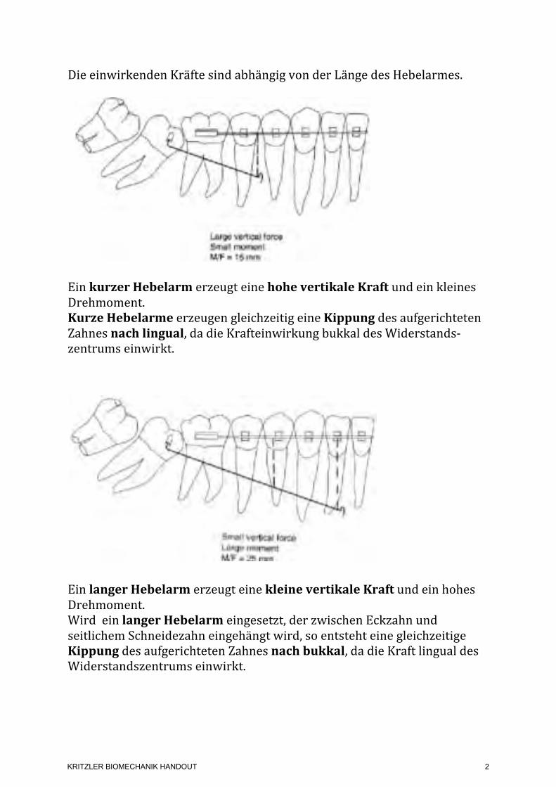
Die einwirkenden Kräfte sind abhängig von der Länge des Hebelarmes.
Ein kurzer Hebelarm erzeugt eine hohe vertikale Kraft und ein kleines Drehmoment. Kurze Hebelarme erzeugen gleichzeitig eine Kippung des aufgerichteten Zahnes nach lingual, da die Krafteinwirkung bukkal des Widerstands-‐zentrums einwirkt.
Ein langer Hebelarm erzeugt eine kleine vertikale Kraft und ein hohes Drehmoment. Wird ein langer Hebelarm eingesetzt, der zwischen Eckzahn und seitlichem Schneidezahn eingehängt wird, so entsteht eine gleichzeitige Kippung des aufgerichteten Zahnes nach bukkal, da die Kraft lingual des Widerstandszentrums einwirkt.
displacement of the T-loop to one side or the other produces a significant change in the force system. With a cantilever system, since the two forces acting on the molar both deliver anuprighting moment, the moment cannot be changed to a geometry IV or lower. The relative moment-to-force ratio can, however, be varied by the activation of the cantilevers, making thesystem easy to control.13
Figures
Fig. 1A Two different lengths of cantilever used for uprighting. Long cantilever (See Fig. 1B) delivers moment-to-force ratio of 25, compared to 15 for shorter cantilever.
Fig. 1B Two different lengths of cantilever used for uprighting. Long cantilever delivers moment-to-force ratio of 25, compared to 15 for shorter cantilever (See Fig. 1A).
Fig. 2 Force systems produced by different positions of "V" bends.
KRITZLER BIOMECHANIK HANDOUT
2
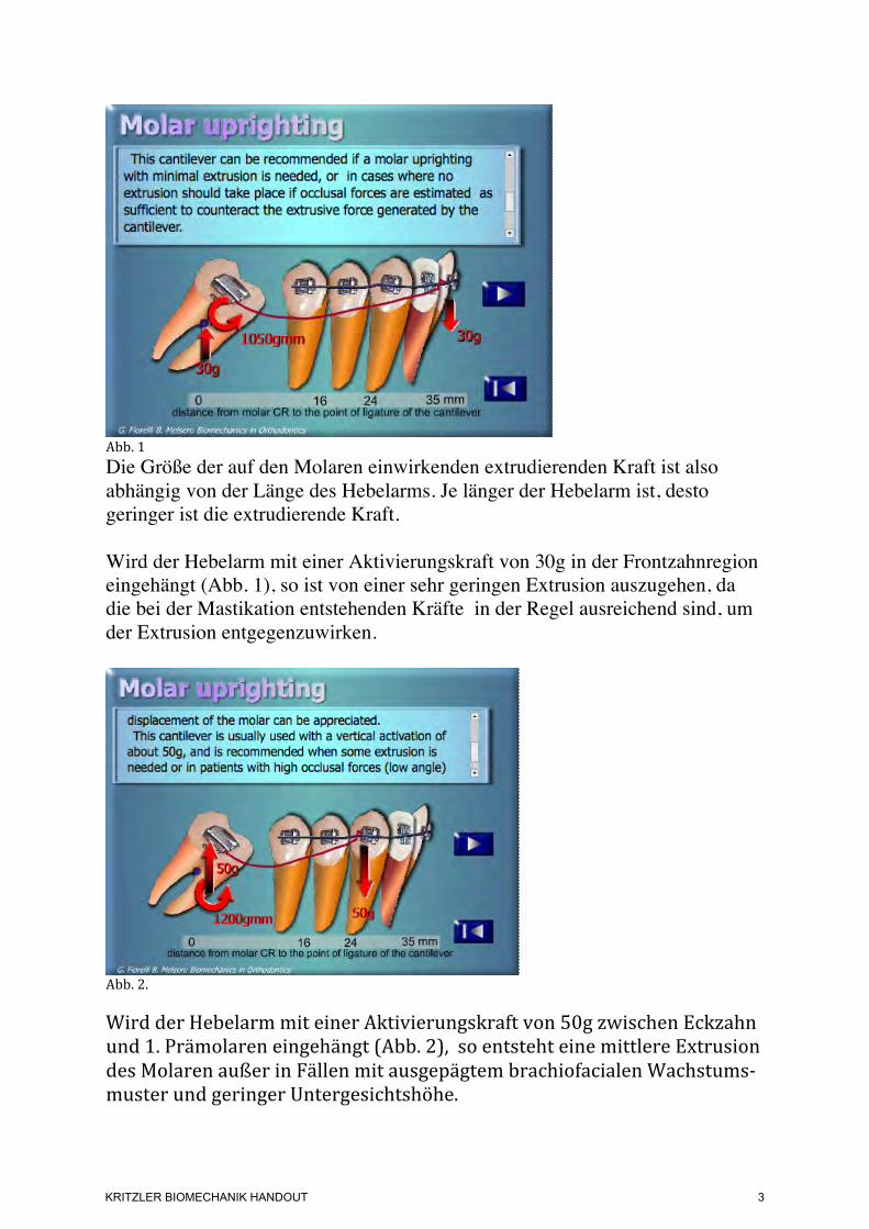
Abb. 1 Die Größe der auf den Molaren einwirkenden extrudierenden Kraft ist also abhängig von der Länge des Hebelarms. Je länger der Hebelarm ist, desto geringer ist die extrudierende Kraft. Wird der Hebelarm mit einer Aktivierungskraft von 30g in der Frontzahnregion eingehängt (Abb. 1), so ist von einer sehr geringen Extrusion auszugehen, da die bei der Mastikation entstehenden Kräfte in der Regel ausreichend sind, um der Extrusion entgegenzuwirken.
Abb. 2. Wird der Hebelarm mit einer Aktivierungskraft von 50g zwischen Eckzahn und 1. Prämolaren eingehängt (Abb. 2), so entsteht eine mittlere Extrusion des Molaren außer in Fällen mit ausgepägtem brachiofacialen Wachstums-‐muster und geringer Untergesichtshöhe.
KRITZLER BIOMECHANIK HANDOUT
3
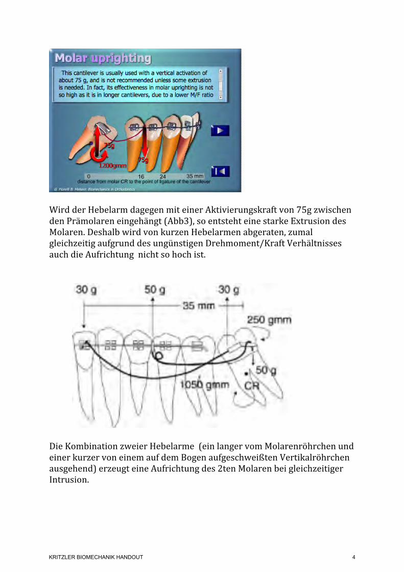
Wird der Hebelarm dagegen mit einer Aktivierungskraft von 75g zwischen den Prämolaren eingehängt (Abb3), so entsteht eine starke Extrusion des Molaren. Deshalb wird von kurzen Hebelarmen abgeraten, zumal gleichzeitig aufgrund des ungünstigen Drehmoment/Kraft Verhältnisses auch die Aufrichtung nicht so hoch ist.
Die Kombination zweier Hebelarme (ein langer vom Molarenröhrchen und einer kurzer von einem auf dem Bogen aufgeschweißten Vertikalröhrchen ausgehend) erzeugt eine Aufrichtung des 2ten Molaren bei gleichzeitiger Intrusion.
Fig. 5A3 Case 2. 17-year-old male with second molars tipped mesially.
Fig. 5B Case 2. Force system used on left side: two cantilevers, one extending from molar tube and one from vertical tube welded to main arch, both delivering desirable moments tomolar. Sum of forces produces slight intrusive force against molar.
Fig. 5C1 Case 2. Appliance used on left side.
Fig. 5C2 Case 2. Appliance used on left side.
KRITZLER BIOMECHANIK HANDOUT
4
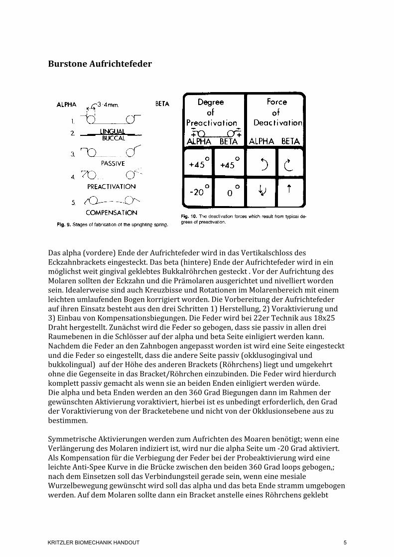
Burstone Aufrichtefeder
Das alpha (vordere) Ende der Aufrichtefeder wird in das Vertikalschloss des Eckzahnbrackets eingesteckt. Das beta (hintere) Ende der Aufrichtefeder wird in ein möglichst weit gingival geklebtes Bukkalröhrchen gesteckt . Vor der Aufrichtung des Molaren sollten der Eckzahn und die Prämolaren ausgerichtet und nivelliert worden sein. Idealerweise sind auch Kreuzbisse und Rotationen im Molarenbereich mit einem leichten umlaufenden Bogen korrigiert worden. Die Vorbereitung der Aufrichtefeder auf ihren Einsatz besteht aus den drei Schritten 1) Herstellung, 2) Voraktivierung und 3) Einbau von Kompensationsbiegungen. Die Feder wird bei 22er Technik aus 18x25 Draht hergestellt. Zunächst wird die Feder so gebogen, dass sie passiv in allen drei Raumebenen in die Schlösser auf der alpha und beta Seite einligiert werden kann. Nachdem die Feder an den Zahnbogen angepasst worden ist wird eine Seite eingesteckt und die Feder so eingestellt, dass die andere Seite passiv (okklusogingival und bukkolingual) auf der Höhe des anderen Brackets (Röhrchens) liegt und umgekehrt ohne die Gegenseite in das Bracket/Röhrchen einzubinden. Die Feder wird hierdurch komplett passiv gemacht als wenn sie an beiden Enden einligiert werden würde. Die alpha und beta Enden werden an den 360 Grad Biegungen dann im Rahmen der gewünschten Aktivierung voraktiviert, hierbei ist es unbedingt erforderlich, den Grad der Voraktivierung von der Bracketebene und nicht von der Okklusionsebene aus zu bestimmen. Symmetrische Aktivierungen werden zum Aufrichten des Moaren benötigt; wenn eine Verlängerung des Molaren indiziert ist, wird nur die alpha Seite um -‐20 Grad aktiviert. Als Kompensation für die Verbiegung der Feder bei der Probeaktivierung wird eine leichte Anti-‐Spee Kurve in die Brücke zwischen den beiden 360 Grad loops gebogen,; nach dem Einsetzen soll das Verbindungsteil gerade sein, wenn eine mesiale Wurzelbewegung gewünscht wird soll das alpha und das beta Ende stramm umgebogen werden. Auf dem Molaren sollte dann ein Bracket anstelle eines Röhrchens geklebt
182 Roberts, Chacker, and Burstone Am J. Orthod. March 1982
Fig. 8. Buccal and occlusal views (photographed at different stages of treatment) of the molar- uprighting appliance. The spring is offset lingually in the edentulous area for added patient comfort.
ALPHA J3 -4mm. I 1 I
1. --c
BETA
PASSIVE _’ r-
4. ro PREACTIVATION
5. /fl--dY COMPENSATION
Fig. 9. Stages of fabrication of the uprighting spring.
prevent spacing and inserted into the occlusal slot of the canine bracket.
There are several alternatives to stabilizing the an- terior segment as suggested in the previous paragraph: (1) The lingual arch wire may be replaced by bracket- ing of the incisors labially and continuing the labial stabilizing wire from the premolar area on the side of the uprighting to the canine or beyond on the opposite side. In this manner, segmental molar uprighting may also be incorporated into concomitant comprehensive orthodontic treatment. (2) The lingual arch may extend to the premolars and molars, if desired, and lingually bonded to each tooth in the anchorage segment.
The alpha (anterior) portion of the uprighting spring inserts into the gingival slot of the canine bracket. The beta (posterior) attachment, into which inserts the beta portion of the uprighting spring, is ideally a rectangular buccal tube, bonded so that gingival irritation is mini-
c 4
Degree Force Of of
Preactivation Deactivation
ALPHA BETA ~ALPHA BETA 4
0 +45 +45 O 3c
-20~ 0 o LJ t
I 4 Fig. 10. The deactivation forces which result from typical de- grees of preadivation.
mized and placed far gingivally in order to facilitate occlusal adjustment of the molar. Prior to correction of inclination of the molar, the canine and premolar(s) should be consolidated and aligned. Ideally, molar ro- tations and cross-bite should also be corrected with a light continuous wire, offset to the angulation of the inclined molar.
Fabrication, preactivation, and compensation com- pose the three steps which prepare the uprighting spring for insertion (Fig. 9). The spring is composed of ap- proximately 0.018 by 0.025 inch wire for insertion into a 0.022 by 0.028 inch bracket. A 0.018 by 0.025 inch bracket would require a corresponding wire size. The uprighting spring is constructed to fit passively (in all three planes of space) into alpha and beta positions.
KRITZLER BIOMECHANIK HANDOUT
5
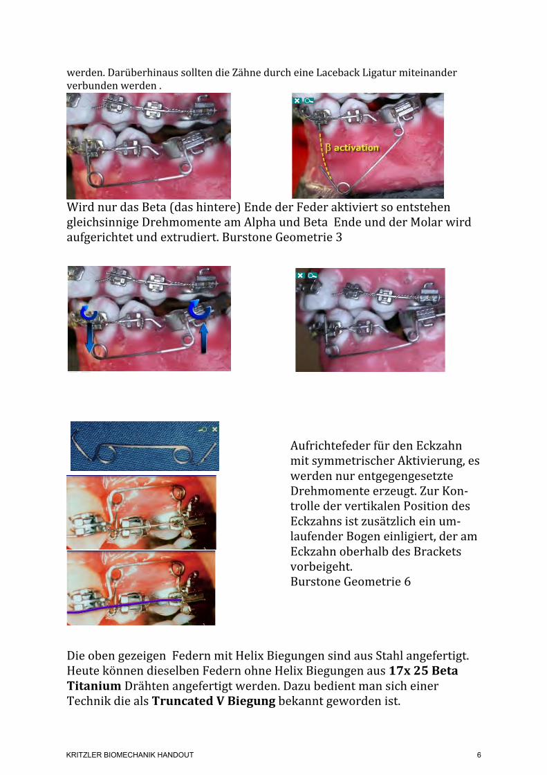
werden. Darüberhinaus sollten die Zähne durch eine Laceback Ligatur miteinander verbunden werden .
Wird nur das Beta (das hintere) Ende der Feder aktiviert so entstehen gleichsinnige Drehmomente am Alpha und Beta Ende und der Molar wird aufgerichtet und extrudiert. Burstone Geometrie 3
Aufrichtefeder für den Eckzahn mit symmetrischer Aktivierung, es werden nur entgegengesetzte Drehmomente erzeugt. Zur Kon-‐trolle der vertikalen Position des Eckzahns ist zusätzlich ein um-‐laufender Bogen einligiert, der am Eckzahn oberhalb des Brackets vorbeigeht. Burstone Geometrie 6
Die oben gezeigen Federn mit Helix Biegungen sind aus Stahl angefertigt. Heute können dieselben Federn ohne Helix Biegungen aus 17x 25 Beta Titanium Drähten angefertigt werden. Dazu bedient man sich einer Technik die als Truncated V Biegung bekannt geworden ist.
With the introduction of beta-titanium the necessity of inserting loops in the
With the introduction of beta-titanium the necessity of inserting loops in the
With the introduction of beta-titanium the necessity of inserting loops in the
With the introduction of beta-titanium the necessity of inserting loops in the
With the introduction of beta-titanium the necessity of inserting loops in the
With the introduction of beta-titanium the necessity of inserting loops in the
KRITZLER BIOMECHANIK HANDOUT
6
Teil-‐Bögen mit Truncated V Biegung
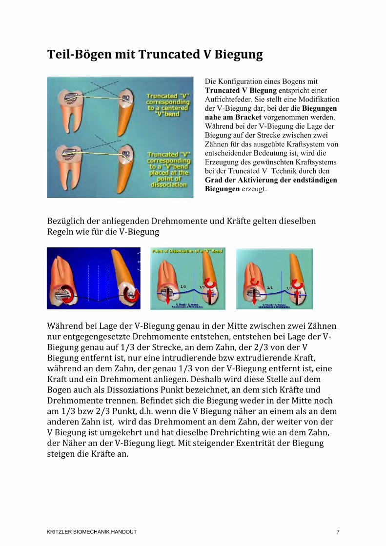
Die Konfiguration eines Bogens mit Truncated V Biegung entspricht einer Aufrichtefeder. Sie stellt eine Modifikation der V-Biegung dar, bei der die Biegungen nahe am Bracket vorgenommen werden. Während bei der V-Biegung die Lage der Biegung auf der Strecke zwischen zwei Zähnen für das ausgeübte Kraftsystem von entscheidender Bedeutung ist, wird die Erzeugung des gewünschten Kraftsystems bei der Truncated V Technik durch den Grad der Aktivierung der endständigen Biegungen erzeugt.
Bezüglich der anliegenden Drehmomente und Kräfte gelten dieselben Regeln wie für die V-‐Biegung
Während bei Lage der V-‐Biegung genau in der Mitte zwischen zwei Zähnen nur entgegengesetzte Drehmomente entstehen, entstehen bei Lage der V-‐Biegung genau auf 1/3 der Strecke, an dem Zahn, der 2/3 von der V Biegung entfernt ist, nur eine intrudierende bzw extrudierende Kraft, während an dem Zahn, der genau 1/3 von der V-‐Biegung entfernt ist, eine Kraft und ein Drehmoment anliegen. Deshalb wird diese Stelle auf dem Bogen auch als Dissoziations Punkt bezeichnet, an dem sich Kräfte und Drehmomente trennen. Befindet sich die Biegung weder in der Mitte noch am 1/3 bzw 2/3 Punkt, d.h. wenn die V Biegung näher an einem als an dem anderen Zahn ist, wird das Drehmoment an dem Zahn, der weiter von der V Biegung ist umgekehrt und hat dieselbe Drehrichting wie an dem Zahn, der Näher an der V-‐Biegung liegt. Mit steigender Exentrität der Biegung steigen die Kräfte an.
and it is the degree of bending -with respect to them- that determines the geometry, i.e., the 'V position'. The configuration of the truncated 'V' is identical to that of the root spring, i.e.,
the α/β spring. Utilizing a truncated 'V' instead of a real 'V' bend does offer several advantages. Due to the position of the bends close to the bracket, it does not slide, with respect to the bracket itself; It is less sensible for small displacements, which can change the force system. Furthermore, it is considerably more comfortable for the patient.
9. Minor Bends - Bends and alignments
11/17 - 221/661
The purpose of both this and the previous chapter is to have the clinician understand the force system developed in relation to three typical situations: 1) The force system generated by a wire passing through two malaligned brackets. 2) The force system generated when a wire with bends is tied into two aligned brackets. 3) The force system generated when a wire with bends is tied into malaligned brackets. !
9. Minor Bends - Activation with respect to alpha and beta
12/17 - 222/661
In the case of malaligned brackets, a wire with minor bends can be used; but the predictability of the force system depends on the clinician's capacity to independently find and evaluate the activation relative to the two units. The total activation with respect to the two brackets is produced by the mislalignment, Additionally it relates to the wire bending.
An identical force system to two units can be developed by a rectangular loop; and the mutual position of the brackets to a straight wire reflects a geometry IV. This position of the 'V' bend is called the point of dissociation; thus, forces are dissociated from moments.
In those cases, where the 'V' bend is positioned more eccentrically ,
i.e., when the bend is close to one or the other teeth, the moment acting on the bracket at the larger distance from the bend is reversed. It will have the same direction as the one on the adjacent tooth. The force system approaches that of a geometry III. The forces gradually increase with increasing eccentricity.
'V bend position and force system
9. Minor Bends - General rules
7/17 - 217/661 As already mentioned under the force systems, generated by a straight wire, the 'V' bend and the step bend follow the same general rules, with respect to the developed force systems.
KRITZLER BIOMECHANIK HANDOUT
7
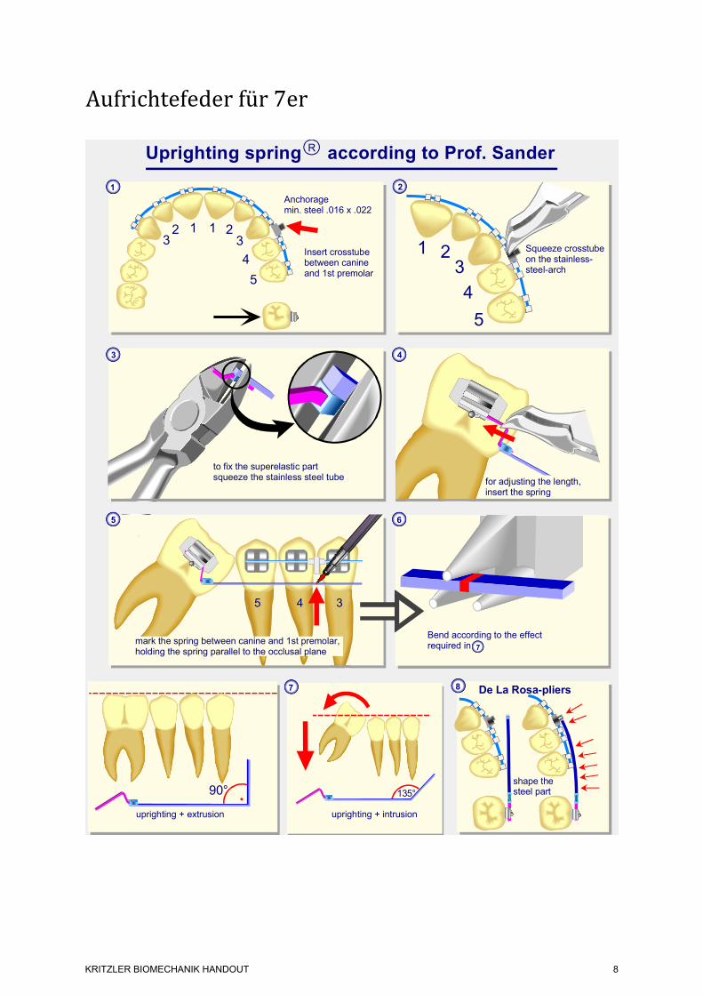
Aufrichtefeder für 7er
1
5
4
321
Insert crosstube between canine and 1st premolar
Anchorage min. steel .016 x .022
5
4
321
2
Squeeze crosstube on the stainless-steel-arch
Uprighting spring according to Prof. SanderR
123
135°
uprighting + intrusion
7
5 4 3
8
shape the steel part
De La Rosa-pliers
6
to fix the superelastic part squeeze the stainless steel tube
3 4
5
mark the spring between canine and 1st premolar, holding the spring parallel to the occlusal plane
V3
for adjusting the length,insert the spring
http://www.DocSander.de
Bend according to the effectrequired in 7
uprighting + extrusion
90°
04.12.2009
KRITZLER BIOMECHANIK HANDOUT
8
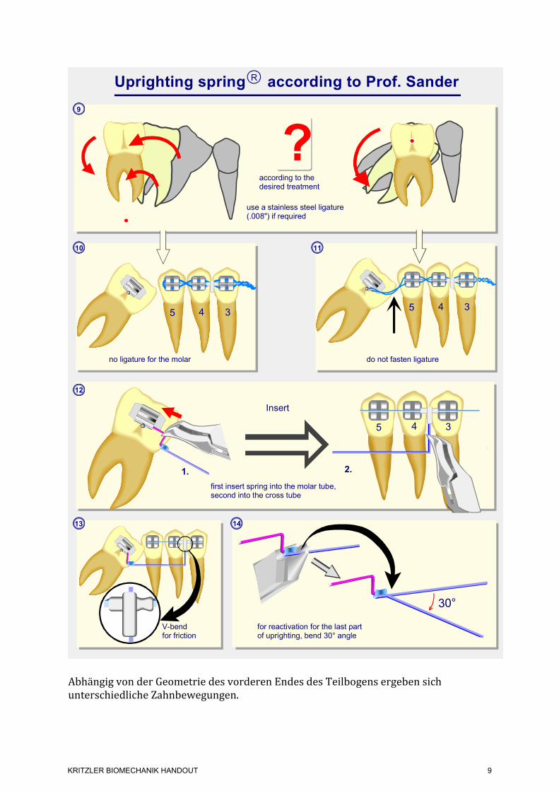
Abhängig von der Geometrie des vorderen Endes des Teilbogens ergeben sich unterschiedliche Zahnbewegungen.
14
Insert
12
2.
5 4 3
1.
5 4 3
9
for reactivation for the last part of uprighting, bend 30° angle
use a stainless steel ligature (.008") if required
do not fasten ligature
first insert spring into the molar tube, second into the cross tube
5 4 3
10
?
13
V-bendfor friction
according to thedesired treatment
no ligature for the molar
Uprighting spring according to Prof. SanderR
11
30°
http://www.DocSander.de04.12.2009
V 03
KRITZLER BIOMECHANIK HANDOUT
9
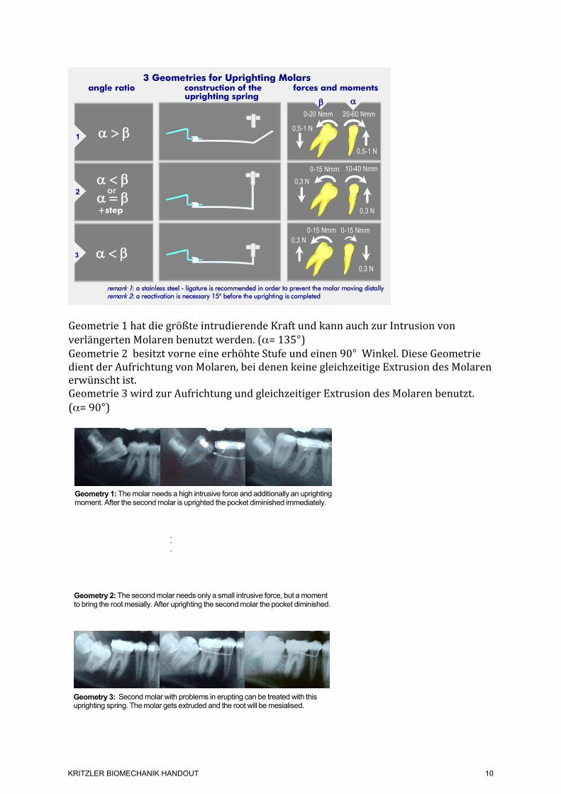
Geometrie 1 hat die größte intrudierende Kraft und kann auch zur Intrusion von verlängerten Molaren benutzt werden. (α= 135°) Geometrie 2 besitzt vorne eine erhöhte Stufe und einen 90° Winkel. Diese Geometrie dient der Aufrichtung von Molaren, bei denen keine gleichzeitige Extrusion des Molaren erwünscht ist. Geometrie 3 wird zur Aufrichtung und gleichzeitiger Extrusion des Molaren benutzt. (α= 90°)
D�!�E
D���E
D� �E+step
D���Eor
0-20 Nmm
0,5-1 N
0-15 Nmm0,3 N
0,3 N
E D angle ratio construction of the forces and moments uprighting spring
1
2
3
20-60 Nmm
0,5-1 N
10-40 Nmm
0-15 Nmm 0-15 Nmm
0,3 N
0,3 N
3 Geometries for Uprighting Molars
remark 1: a stainless steel - ligature is recommended in order to prevent the molar moving distallyremark 2: a reactivation is necessary 15° before the uprighting is completed
Geometry 1: The molar needs a high intrusive force and additionally an uprightingmoment. After the second molar is uprighted the pocket diminished immediately.
Geometry 2: The second molar needs only a small intrusive force, but a momentto bring the root mesially. After uprighting the second molar the pocket diminished.
Geometry 3: Second molar with problems in erupting can be treated with thisuprighting spring. The molar gets extruded and the root will be mesialised.
For uprighting molars it is important to have a superelastic NiTi-SE-stainless steel uprighting spring and a cross tube. This uprighting spring is preformed without any angulation in the stainless steel part. The cross tube is fixed distally to the canine on a very rigid stainless steel arch wire with a minimum dimension of .017"x.025". In case there is no canine-canine retainer it is necessary to use this rigid part from one side to the opposite side even in uprighing one molar.Depending on the individual oral situation three geometries of the uprighting spring can be chosen.
Geometry 1 has the highest intrusive force and can also be used to intrude uprighted molars with a force of about 1 N. (D�= 135°)Geometry 2 has additionally a vertical step of 3 or 4 mm and an D�-angle of 90°.This geometry is useful in uprighting molars if no extrusion is desired.Geometry 3 is useful for uprighting and extruding molars. (D�= 90°)
With this NiTi-SE-stainless steel uprighting spring even horizontally tilted molars can be uprighted. In many cases the distalising force is not desired so that a stainless steel ligature not tight but loosely fixed between the molar and the cross tube is recommended.About 15° before optimal uprighting of the molar a new reactivation in the tip-back bend is necessary. This can be done in the superelastic part with the Memory-Maker (30°) or in the stainless steel portion very close to the crimped connection.The three samples shown may give useful hints for treating patients.http://www.DocSander.de 21. 10. 2010
V1a
KRITZLER BIOMECHANIK HANDOUT
10
Molarenaufrichtung mit skelettaler Verankerung Verwendung der Aufrichtefeder nach Sander mit Minischrauben
Ludwig et al. Molarenaufrichtung über Miniimplantate48
Kieferorthopädie 2010;24(1):47–54
Mechanische Grundlagen
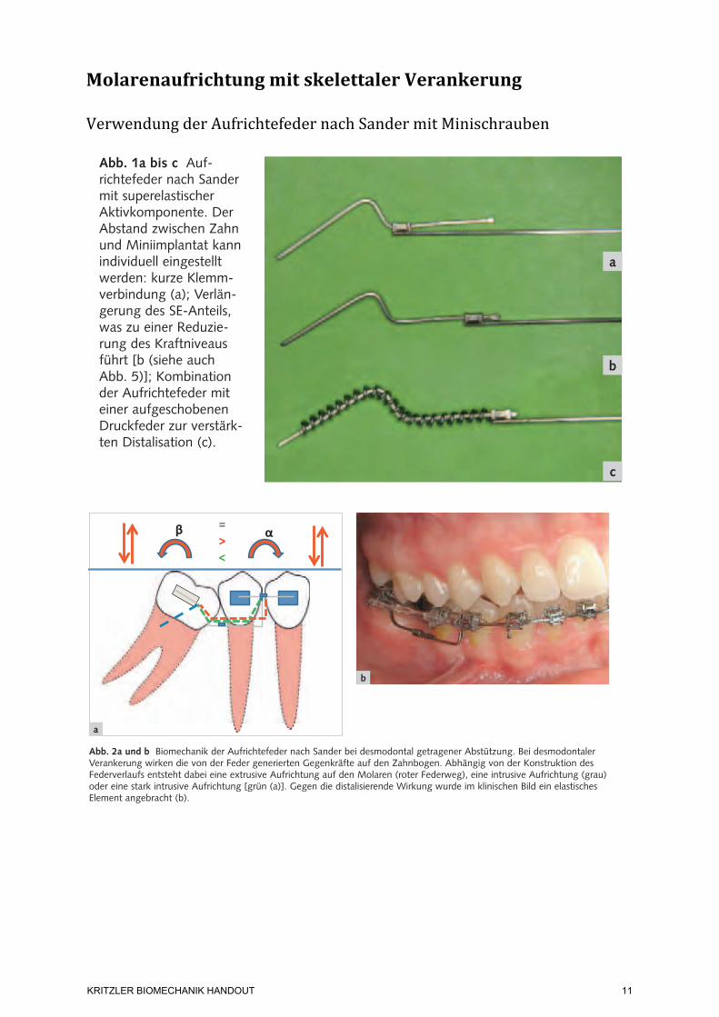
Die Aufrichtungsmechanik erfolgt über eine teilkon-fektionierte Aufrichtefeder nach Sander (Forestadent, Pforzheim)1,2, die wir bedarfsabhängig in drei Varia-tionen einsetzen (Abb. 1a bis c). Die Feder besteht in ihrem Lieferzustand aus einem superelastischen voraktivierten Teil, der mit einem Stahlbogen durch eine verstellbare Klemmkopplung verbunden ist.
Die Aufrichtefeder überträgt neben dem rotativen Moment zusätzliche sagittale und vertikale Effekte, die sowohl auf den zu bewegenden Zahn als auch auf die Abstützungseinheit einwirken (Abb. 2a und b).
Bei der Molarenaufrichtung mittels skelettaler Verankerung kann eine reine 2-Punkt-Abstützung gebildet werden (Abb. 3). Der Kraftansatz liegt bei diesem System im Molaren-Tube, die reaktiven Kräfte werden über das Miniimplantat auf den Knochen übertragen und dort absorbiert. Das Miniimplantat wird in der Regel interradikulär zwischen den Prä-molaren inseriert und sollte eine intraossäre Länge zwischen 6 und 8 mm sowie einen transgingivalen Anteil von etwa 2 mm aufweisen.
Nachdem der superelastische voraktivierte Teil der Feder in das Molarenbracket eingeführt ist, wird der horizontale Stahlbogen situationsentsprechend abgelängt und an seinem Ende L-förmig umgebo-gen. Für eine stabile und rutschsichere Kopplung zum Miniimplantat sollte ein Schraubentyp mit Kreuzslot gewählt werden, der im Zentrum des Kreuzes rund gearbeitet ist, da die Biegung des Drahtes über eine Zange anstelle einer exakten 90°-Abwinklung eine geringe Kurvatur ergibt. Um aufwändige Adaptati-onen des Stahlteils zu vermeiden, ist bei der Inser-tion der Schraube auf die horizontale Ausrichtung des Slots, parallel zur Okklusionsebene, zu achten. Die 90°-Abwinklung wird dann in das Zentrum des Kreuzslots eingelegt, im vertikalen Slotanteil nach unten geführt und mit einer Drahtligatur gesichert (Abb. 3).
Abb. 1a bis c Auf-richtefeder nach Sander mit superelastischer Aktivkomponente. Der Abstand zwischen Zahn und Miniimplantat kann individuell eingestellt werden: kurze Klemm-verbindung (a); Verlän-gerung des SE-Anteils, was zu einer Reduzie-rung des Kraftniveaus führt [b (siehe auch Abb. 5)]; Kombination der Aufrichtefeder mit einer aufgeschobenen Druckfeder zur verstärk-ten Distalisation (c).
a
c
b
Abb. 2a und b Biomechanik der Aufrichtefeder nach Sander bei desmodontal getragener Abstützung. Bei desmodontaler Verankerung wirken die von der Feder generierten Gegenkräfte auf den Zahnbogen. Abhängig von der Konstruktion des Federverlaufs entsteht dabei eine extrusive Aufrichtung auf den Molaren (roter Federweg), eine intrusive Aufrichtung (grau) oder eine stark intrusive Aufrichtung [grün (a)]. Gegen die distalisierende Wirkung wurde im klinischen Bild ein elastisches Element angebracht (b).
a
b
Ludwig et al. Molarenaufrichtung über Miniimplantate48
Kieferorthopädie 2010;24(1):47–54
Mechanische Grundlagen
Die Aufrichtungsmechanik erfolgt über eine teilkon-fektionierte Aufrichtefeder nach Sander (Forestadent, Pforzheim)1,2, die wir bedarfsabhängig in drei Varia-tionen einsetzen (Abb. 1a bis c). Die Feder besteht in ihrem Lieferzustand aus einem superelastischen voraktivierten Teil, der mit einem Stahlbogen durch eine verstellbare Klemmkopplung verbunden ist.
Die Aufrichtefeder überträgt neben dem rotativen Moment zusätzliche sagittale und vertikale Effekte, die sowohl auf den zu bewegenden Zahn als auch auf die Abstützungseinheit einwirken (Abb. 2a und b).
Bei der Molarenaufrichtung mittels skelettaler Verankerung kann eine reine 2-Punkt-Abstützung gebildet werden (Abb. 3). Der Kraftansatz liegt bei diesem System im Molaren-Tube, die reaktiven Kräfte werden über das Miniimplantat auf den Knochen übertragen und dort absorbiert. Das Miniimplantat wird in der Regel interradikulär zwischen den Prä-molaren inseriert und sollte eine intraossäre Länge zwischen 6 und 8 mm sowie einen transgingivalen Anteil von etwa 2 mm aufweisen.
Nachdem der superelastische voraktivierte Teil der Feder in das Molarenbracket eingeführt ist, wird der horizontale Stahlbogen situationsentsprechend abgelängt und an seinem Ende L-förmig umgebo-gen. Für eine stabile und rutschsichere Kopplung zum Miniimplantat sollte ein Schraubentyp mit Kreuzslot gewählt werden, der im Zentrum des Kreuzes rund gearbeitet ist, da die Biegung des Drahtes über eine Zange anstelle einer exakten 90°-Abwinklung eine geringe Kurvatur ergibt. Um aufwändige Adaptati-onen des Stahlteils zu vermeiden, ist bei der Inser-tion der Schraube auf die horizontale Ausrichtung des Slots, parallel zur Okklusionsebene, zu achten. Die 90°-Abwinklung wird dann in das Zentrum des Kreuzslots eingelegt, im vertikalen Slotanteil nach unten geführt und mit einer Drahtligatur gesichert (Abb. 3).
Abb. 1a bis c Auf-richtefeder nach Sander mit superelastischer Aktivkomponente. Der Abstand zwischen Zahn und Miniimplantat kann individuell eingestellt werden: kurze Klemm-verbindung (a); Verlän-gerung des SE-Anteils, was zu einer Reduzie-rung des Kraftniveaus führt [b (siehe auch Abb. 5)]; Kombination der Aufrichtefeder mit einer aufgeschobenen Druckfeder zur verstärk-ten Distalisation (c).
a
c
b
Abb. 2a und b Biomechanik der Aufrichtefeder nach Sander bei desmodontal getragener Abstützung. Bei desmodontaler Verankerung wirken die von der Feder generierten Gegenkräfte auf den Zahnbogen. Abhängig von der Konstruktion des Federverlaufs entsteht dabei eine extrusive Aufrichtung auf den Molaren (roter Federweg), eine intrusive Aufrichtung (grau) oder eine stark intrusive Aufrichtung [grün (a)]. Gegen die distalisierende Wirkung wurde im klinischen Bild ein elastisches Element angebracht (b).
a
b
KRITZLER BIOMECHANIK HANDOUT
11
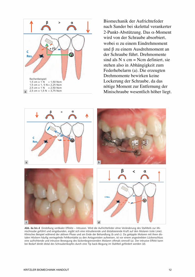
Biomechanik der Aufrichtefeder nach Sander bei skelettal verankerter 2-Punkt-Abstützung. Das α-Moment wird von der Schraube absorbiert, wobei α zu einem Eindrehmoment und β zu einem Ausdrehmoment an der Schraube führt. Drehmomente sind als N x cm = Ncm definiert, sie stehen also in Abhängigkeit zum Federhebelarm (a). Die erzeugten Drehmomente bewirken keine Lockerung der Schraube, da das nötige Moment zur Entfernung der Minischraube wesentlich höher liegt.
Ludwig et al. Molarenaufrichtung über Miniimplantate 49
Kieferorthopädie 2010;24(1):47–54
Kraftniveau der Aufrichtefeder
In der Literatur wurde bereits diskutiert, dass die Ge-genkraft des Aufrichtemoments zu einer Lockerung oder Ausdrehung des Miniimplantats führen kann3. Im Gegensatz zu Schrauben mit einem Rechtsge-winde würde das Gegenmoment der Aufrichte-mechanik bei einem Linksgewinde, gleichbedeu-tend einer Eindrehung entgegen dem Uhrzeigersinn, an der Schraube zu einer Belastung in Eindrehrichtung führen. Die für einen Molaren nötige Aufrichte-größe wird im Bereich ab 1,5 Ncm angegeben1. Zum Ausdrehen einer Minischraube wird eine Kraft > 9-10 Ncm benötigt4,5. Das Drehmoment (Ncm) ist das Produkt aus Kraft (Newton) und der Länge des Hebelarmes (in Zentimeter), wobei 1 N etwa der Gewichtskraft von 100 g entspricht. Schätzt man die Länge des Hebelarmes bei der Aufrichtung annähe-rungsweise auf 2 cm, wären für das Ausdrehen einer
Minischraube etwa 500 g (entsprechend 5 N) er-forderlich. Das entspricht einer Kraftgröße, die weit über dem mechanisch applizierten Drehmoment liegt (Abb. 4a bis c). Das Rechenbeispiel verdeutlicht, dass weder Miniimplantate mit Linksgewinde noch die Insertion mehrerer Schrauben für die Aufrichtung von Einzelzähnen notwendig sind.
Abb. 4a bis c Biomechanik der Aufrichtefeder nach Sander bei skelettal verankerter 2-Punkt-Abstützung. Das !-Moment wird von der Schraube absorbiert, wobei ! zu einem Eindreh-moment und " zu einem Ausdrehmoment an der Schraube führt. Drehmomente sind als N x cm = Ncm defi niert, sie ste-hen also in Abhängigkeit zum Federhebelarm (a). Die erzeug-ten Drehmomente bewirken keine Lockerung der Schraube (hier: konventionelle Feder durchgehend aus einem Werk-stoff; Aufrichtefeder nach Sander, siehe auch Abb. 5). Jedoch ergibt sich bei dem hier konstruierten Federverlauf (grau), wie im klinischen Bild durch den erweiterten PA-Spalt ersichtlich, eine Extrusions- und Distalisationskomponente auf den be-wegten Zahn (b). Ausdrehdiagramm einer Minischraube: Die rote Linie zeigt das maximale Drehmoment, das beispielhaft errechnet wurde. Man sieht, dass das nötige Moment zur Entfernung der Minischraube wesentlich höher liegt (c).
Abb. 3 Klinische Situa-tion nach unmittelbarer Insertion des Miniim-plantats, Eingliederung der Aufrichtefeder und Befestigung im Schrau-benkopf über eine Drahtligatur.
0
5
10
15
20
25
30
35
40 6,
4325
64
6,28
0813
5,98
1525
5,62
7438
5,44
6179
5,17
6399
4,88
1327
4,40
9212
3,91
1805
3,62
0948
3,23
3139
2,83
2685
2,45
7522
2,22
1465
2,06
5499
2,03
5992
2,05
7068
2,02
3346
2,57
5551
S_Moment
a
c
Rechenbeispiel:1,5 cm ! 1 N = 1,50 Ncm1,5 cm ! 1, 5 N = 2,25 Ncm2,5 cm ! 1 N = 2,50 Ncm2,5 cm ! 1,5 N = 3,75 Ncm b
Ludwig et al. Molarenaufrichtung über Miniimplantate 51
Kieferorthopädie 2010;24(1):47–54
Darüber hinaus gilt es, den Zusammenhang zwi-schen der Insertionshöhe des Miniimplantats und dem Kraftansatz der Feder am Molaren zu beden-ken. Meist wird das Miniimplantat in den Interra-dikulärraum 4 / 5 bzw. gelegentlich auch 3 / 4 und aufgrund der anatomischen Raumverhältnisse in ei-nem Abstand zur Slotebene von etwa 1 cm inseriert. Die Länge der Feder variiert somit in Abhängigkeit des Insertionsortes und der Strecke bis zum Angriffs-ort (z. B. Aufrichtung eines in die Lücke gekippten Nachbarzahnes) zwischen 1,5 und 2,5 cm. Die Ab-bildungen 5a bis c und die Tabellen 1a und b zeigen einen Versuchsaufbau aus einer aktuell betreuten Dissertation, in der die mechanischen Auswirkungen der vertikalen Schraubenposition auf die Kraftbilanz untersucht werden.
Vertikale Effekte – Steuerung von Extrusion und Intrusion
Ein weiterer Vorteil der konfektionierten Feder be-steht in der Möglichkeit, über den Stahlteil zusätzlich eine steuerbare vertikale Komponente zu übertra-gen. Für eine intrusive Wirkung wird der Stahldraht so abgewinkelt, dass der SE-Anteil unterhalb des Bracket-Slots liegt (Abb. 6a bis d). Für eine extrusive Komponente muss sich die Feder in ihrem passiven Zustand oberhalb des Bracket-Slots befi nden (Abb. 7a bis g). Lassen es die intraoralen Verhältnisse in Bezug auf das Knochenangebot und die Höhe der befestigten Gingiva zu, können intrusive bzw. ext-rusive Effekte auch über die vertikale Positionierung des Miniimplantats generiert werden.
Abb. 6a bis d Einstellung vertikaler Effekte – Intrusion. Wird die Aufrichtefeder ohne Veränderung des Stahlteils zur Mi-nischraube geführt und eingebunden, ergibt sich eine intrudierende und distalisierende Kraft auf den Molaren (rote Linie). Klinisches Beispiel während der aktiven Phase und am Ende der Behandlung (b und c). Da gekippte Molaren mit ihren dis-talen Höckern häufi g verriegelnde Fehlkontakte zu den Antagonisten aufweisen, ist vor einem angestrebten Lückenschluss eine aufrichtende und intrusive Bewegung des lückenbegrenzenden Molaren oftmals sinnvoll (a). Der intrusive Effekt kann bei Bedarf direkt distal des Schraubenkopfes durch eine Tip back-Biegung im Stahlteil gefördert werden (d).
a b
c d
KRITZLER BIOMECHANIK HANDOUT
12
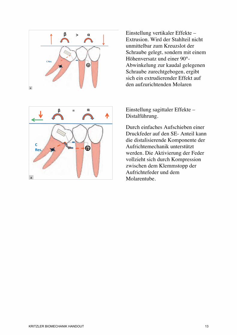
Einstellung vertikaler Effekte – Extrusion. Wird der Stahlteil nicht unmittelbar zum Kreuzslot der Schraube gelegt, sondern mit einem Höhenversatz und einer 90°-Abwinkelung zur kaudal gelegenen Schraube zurechtgebogen, ergibt sich ein extrudierender Effekt auf den aufzurichtenden Molaren
Einstellung sagittaler Effekte – Distalführung.
Durch einfaches Aufschieben einer Druckfeder auf den SE- Anteil kann die distalisierende Komponente der Aufrichtemechanik unterstützt werden. Die Aktivierung der Feder vollzieht sich durch Kompression zwischen dem Klemmstopp der Aufrichtefeder und dem Molarentube.
Ludwig et al. Molarenaufrichtung über Miniimplantate52
Kieferorthopädie 2010;24(1):47–54
Sagittale Effekte – Steuerung des Lückenmanagements
Neben dem Aufrichtemoment und der vertikalen Komponente entsteht durch die Aktivierung der Fe-der – wie bereits beschrieben – auch eine sagittale Kraft, die zu einer Distalisation des Molaren führt. Ist
eine Distalwirkung gewünscht, wird der superelasti-sche Teil nach dem Durchtritt durch das Molarenbra-cket mit Längenzugabe distal abgeknipst, was eine Aufrichtung und eine gewisse Distalisationsbewe-gung zur Folge hat. Verstärkend kann der SE-Anteil mit einer Druckfeder kombiniert werden (Abb. 7b bis g und 8a bis c). Für eine reine Aufrichtung ohne Distalisierung des Molaren ist ein eng anliegender und stabiler Stopp hinter dem Molarenröhrchen not-wendig.
Benötigt die präprothetische Behandlung eine Verkleinerung der Lückensituation, was beispiels-weise bei Verlust zweier benachbarter Zähne der Fall sein kann, oder soll nach dem Aufrichtung des Molaren ein kieferorthopädischer Lückenschluss durchgeführt werden, muss der bewegte Zahn vor einer hier ungewollten Distalisation durch ein La-ceback geschützt werden. Zur Ermöglichung einer Gleitmechanik sollte dabei die Klemmkopplung der Aufrichtefeder nicht aktiviert werden.
c db
f ge
a
Abb. 7a bis g Einstellung vertikaler Effekte – Extrusion. Wird der Stahlteil nicht unmittelbar zum Kreuzslot der Schraube gelegt, sondern mit einem Höhenversatz und einer 90°-Abwinkelung zur kaudal gelegenen Schraube zurechtgebogen, ergibt sich ein extrudierender Effekt auf den aufzurich-tenden Molaren (a). Klinische Beispiele: Halbretinierter und gekippter 2. unterer Molar. Hier wird die Aufrichtefeder auf Extrusion programmiert, die distalisierende Komponente nicht durch ein Laceback unterbunden und zusammen mit dem Keim des Weisheitszahnes, der als Hypomochlion dient, als Platzquelle genutzt (b bis d). Retinierter und stark gekippter 2. unterer Molar. Die Aufrichtefeder wurde ebenfalls auf Extrusion und durch eine zusätzlich auf den SE-Teil aufgeschobene Druckfeder auf verstärkte Distalisation aktiviert. Der Weisheitszahn wurde aufgrund der ausgeprägten Kippung und des Platzbedarfs für die Aufrichtung aus dem Kontaktbereich zum Sechsjahresmolaren germektomiert (e bis g).
Ludwig et al. Molarenaufrichtung über Miniimplantate 53
Kieferorthopädie 2010;24(1):47–54
Diskussion
Die Aufrichtung gekippter Molaren gehört zu den anspruchsvolleren Aufgaben einer kieferorthopädi-schen Behandlung. Oft ist schon die Platzierung des Brackets auf der bukkalen Schmelzfl äche durch die Kippung oder Halbretention des Zahnes nicht ein-fach. Des Weiteren ist eine Aufrichtung durch eine alleinige, umfassende Straight-wire-Mechanik selten erfolgreich, so dass zusätzliche Elemente für die Bewe-gung eingesetzt werden müssen. In der Literatur wird eine Vielzahl an Möglichkeiten beschrieben, die häu-fi g eine Verankerung über den restlichen Zahnbogen benötigen. Die Mechanik basiert dabei auf Segment-bogentechniken, bei denen der Aufrichte-Cantilever über einen frontalen Teilbogen6, eine konventionelle Straight-wire-Apparatur2,7,8 oder eine linguale adhä-sive Verblockung9 abgestützt wird. Zur Vermeidung einer zahnfassenden Verankerung wurden schon früh Verfahren mit knöcherner Abstützung beschrieben10. Bei der Aufrichtung eines in die Extraktionslücke ge-kippten zweiten Molaren bietet sich eine Veranke-rung über ein permanentes Implantat in der Lücken-region an11. Allerdings können weit aufgewanderte und stark gekippte Zähne eine optimale Implantation
Abb. 8a bis c Einstellung sagittaler Effekte – Distalführung. Durch einfaches Aufschieben einer Druckfeder auf den SE-Anteil kann die distalisierende Komponente der Aufrichte-mechanik unterstützt werden. Die Aktivierung der Feder vollzieht sich durch Kompression zwischen dem Klemmstopp der Aufrichtefeder und dem Molarentube.
limitieren. Die Insertion eines orthodontischen Mini-implantats gibt dem Kieferorthopäden mehr Freiheit für die Eingliederung der Behandlungsmechanik, da Ansatzpunkte und Distanzen situationsbezogen ge-wählt werden können12-14.
Einige Veröffentlichungen berichten über Kraft-ansatzsysteme, bei denen die Schrauben ebenfalls in der Prämolarenregion inseriert wurden12,15. Die Ver-ankerung erfolgte dabei in indirekter Weise, d. h. die Aufrichtefeder wurde zahngetragen befestigt, wobei der Ankerzahn über eine starre Drahtkonstruktion mit dem Miniimplantat verbunden war.
Die Minischraube kann auch vertikal in den zahn-losen Alveolarknochen eingebracht14 und in direkter Verankerung mit der Aufrichtefeder genutzt werden. Dazu muss über dem Schraubenkopf eine Aufnah-mevorrichtung (z. B. Kompositmantel mit integrier-tem Bracket) angepasst werden. Auch über eine Insertion distal des aufzurichtenden Zahnes wurde berichtet, wobei in dieser Region die Stabilität der Schraube häufi g durch eine dicke und bewegliche Schleimhaut eingeschränkt wird14.
Der Vorteil der hier beschriebenen Methode liegt in der einfachen direkten Verankerung, die ohne zu-sätzliche Fixierungen an weiteren Zähnen auskommt.
a
b
c
b
KRITZLER BIOMECHANIK HANDOUT
13
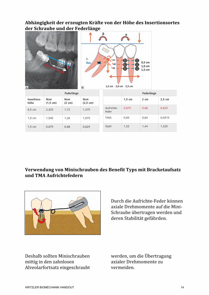
Abhängigkeit der erzeugten Kräfte von der Höhe des Insertionsortes der Schraube und der Federlänge
Verwendung von Minischrauben des Benefit Typs mit Bracketaufsatz und TMA Aufrichtefedern
Durch die Aufrichte-‐Feder können axiale Drehmomente auf die Mini-‐Schraube übertragen werden und deren Stabilität gefährden.
Deshalb sollten Minischrauben mittig in den zahnlosen Alveolarfortsatz eingeschraubt
werden, um die Übertragung axialer Drehmomente zu vermeiden.
Ludwig et al. Molarenaufrichtung über Miniimplantate50
Kieferorthopädie 2010;24(1):47–54
Abb. 5a bis c Versuchs-aufbau zur Bestimmung der angreifenden Kräfte und Momente der Auf-richtemechanik bei un-terschiedlicher vertikaler bzw. sagittaler Ausrich-tung der Minischraube (vertikaler Abstand zur Slotebene 0,5 cm, 1,0 cm und 1,5 cm).
40° gekippter Molar bei einer vertikalen Ausrichtung der Schraube von 1,5 cm
rot = Aufrichtefeder nach Sanderblau = Edelstahlgrün = !-Titan
a b
c
Tab. 1a Drehmomente einer Aufrichtefeder nach Sander bei einem um 40° gekippten Molaren in Bezug zum gewählten Insertionsort und zur Federlänge.
Tab. 1b Drehmomente verschiedener Federqualitäten bei einem um 40° gekippten Molaren und einer konstanten Insertionshöhe von 1,5 cm. Die Aufrichtefeder bietet bei unterschiedlichen Federlängen im Vergleich zu Federn aus Edelstahl oder !-Titan ein zuverlässig konstantes Kraftni-veau.
Federlänge
Insertions-höhe
Ncm (1,5 cm)
Ncm (2 cm)
Ncm (2,5 cm)
0,5 cm 2,325 1,72 1,375
1,0 cm 1,545 1,26 1,075
1,5 cm 0,675 0,68 0,625
Federlänge
1,5 cm 2 cm 2,5 cm
Aufrichte-feder
0,675 0,68 0,625
TMA 0,65 0,64 0,0315
Stahl 1,52 1,44 1,325
Unless a prosthetic replacement is inserted soon after extraction or loss of a first molar, the
second molar may tip mesially into the edentulous space. Not only will the first-molar space contract mesiodistally, but eccentric occlusal loading will reduce the biomechanical loading capacity of the second molar.
Such a situation requires preprosthetic up -righting of the second molar using appropriate mechanics. Simply tipping the molar distally with a statically determined force system will lead to extrusion and likely cause occlusal interference. Therefore, a statically indeterminate system apply-ing both an intrusive force and an uprighting mo -ment of force would be preferable.1 Stable anchorage is critical, since simultaneous intrusion and up -righting forces create a high moment load on the anchorage unit—a Class V geometry under the classification of Burstone and Koenig.2,3 Otherwise,
unwanted mesial tipping and extrusion of the anchorage teeth may occur.
The use of an orthodontic mini-implant for direct anchorage can help avoid such dental side effects. However, an uprighting spring applies an axial moment to a screw inserted in the buccal segment, thus increasing the likelihood of implant failure4 (Fig. 1). This article describes an alterna-
© 2013 JCO, Inc.
Preprosthetic Molar Uprighting Using Skeletal Anchorage
MANUEL NIENKEMPER, DDS, MSCALEXANDER PAULS, DDSBJÖRN LUDWIG, DMD, MSDBENEDICT WILMES, DMD, MSD, PHDDIETER DRESCHER, DMD, PHD
Dr. Ludwig Dr. WilmesDr. Pauls Dr. DrescherDr. Nienkemper
VOLUME XLVII NUMBER 7 433
Dr. Nienkemper is an Instructor, Dr. Pauls is a researcher, Dr. Wilmes is an Associate Professor, and Dr. Drescher is Professor and Head, Department of Orthodontics, University of Düsseldorf, Moorenstrasse 5, 40225 Düsseldorf, Germany. Dr. Wilmes is also a Visiting Professor, Department of Orthodontics, University of Alabama at Birmingham School of Dentistry, and the developer of the Benefit system. Dr. Ludwig is a Contributing Editor of the Journal of Clinical Orthodontics; an Instructor, Department of Orthodontics, University of Homburg, Saar, Germany; and in the private practice of orthodontics in Traben-Trarbach, Germany. E-mail Dr. Nienkemper at [email protected].
Fig. 1 Uprighting spring exerts axial moment on single buccal mini-implant, increasing risk of mini-implant failure.
©2013 JCO, Inc. May not be distributed without permission. www.jco-online.com
KRITZLER BIOMECHANIK HANDOUT
14
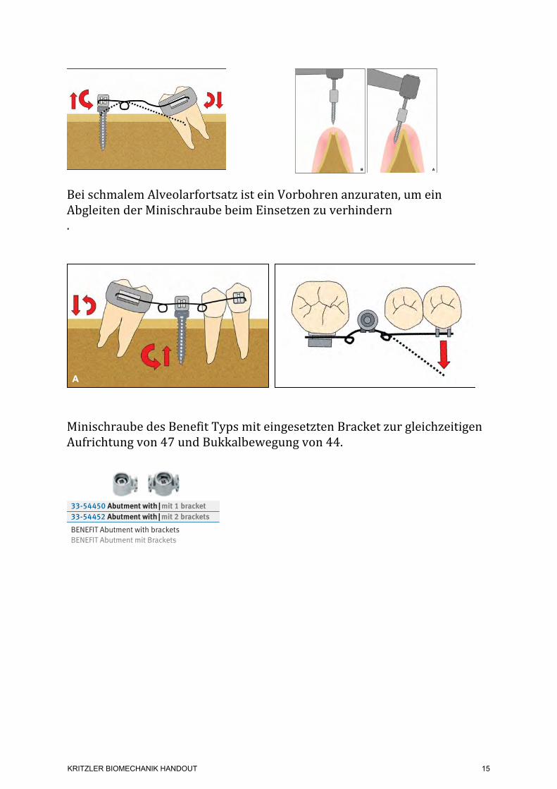
Bei schmalem Alveolarfortsatz ist ein Vorbohren anzuraten, um ein Abgleiten der Minischraube beim Einsetzen zu verhindern.
Minischraube des Benefit Typs mit eingesetzten Bracket zur gleichzeitigen Aufrichtung von 47 und Bukkalbewegung von 44.
Case 1
A 45-year-old female presented with a mesi-ally tipped lower left second molar following previous extraction of the first molar and second premolar. A Benefit mini-implant was inserted into the alveolar ridge, and an uprighting spring was placed and activated according to the procedure described above (Fig. 4A).
Five months later, the lower second molar had been uprighted without any extrusion (Fig. 4B). The mini-implant remained stable throughout treatment and was subsequently used to anchor a temporary crown that would prevent overeruption of the upper dentition.
VOLUME XLVII NUMBER 7 435
Nienkemper, Pauls, Ludwig, Wilmes, and Drescher
Fig. 3 Uprighting spring activated with mesial eccentric V-bend.
Fig. 4 Case 1. 45-year-old female patient with missing lower left second premolar and first molar and mesially tipped lower left second molar. A. Benefit* mini-implant with bracket abutment placed in alveolar ridge for attachment of uprighting spring. B. After five months of molar-uprighting treatment without any extrusion.
A
B
tive technique, using a mini-implant in an edentu-lous first-molar site as anchorage for up righting a mesially tipped second molar.
Insertion Procedure
The mini-implant is inserted in the space of the missing first molar, perpendicular to the gin-gival surface. After a dental probe is used to locate the top of the atrophic alveolar crest and determine the best insertion site in terms of gingival thick-ness, the site is predrilled with a 1.4mm-diameter drill to a depth of about 3mm. Since the alveolar ridge is likely to have atrophied, predrilling will avoid lateral slippage of the mini-implant (Fig. 2).
A Benefit* mini-implant (2mm ! 11mm) is inserted along the dental axis. The head of the Benefit screw has a special inner thread that allows
different kinds of abutments to be attached for various mechanics.5 In this case, an abutment with an .018" bracket is used.
The uprighting spring is bent from .016" ! .022" TMA** wire and inserted between the bracket abutment of the mini-implant and the second-molar band. Activation with a mesial eccentric V-bend3 applies an uprighting moment and an intrusive force to the second molar (Fig. 3). A larger opposite moment and an extrusive force act on the mini-implant. To counteract the buccal tipping moment created by the intrusive force, additional buccal root torque may be applied.
434JCO/JULY 2013
Preprosthetic Molar Uprighting Using Skeletal Anchorage
*PSM Medical Solutions, Tuttlingen, Germany; www.psm.ms. PSM North America, Inc., Indio, CA; www.psm-na.us.
**Registered trademark of Ormco Corporation, Orange, CA; www.ormco.com.
Fig. 2 Insertion of orthodontic mini-implant into narrow alveolar ridge in edentulous molar site. A. Without predrilling, mini-implant can easily slip laterally. B. Predrilling facilitates correct implant placement.
AB
436 JCO/JULY 2013
Fig. 5 Case 2. 51-year-old female patient with mesially tipped lower right second molar and lingually displaced lower right first premolar. A. After insertion of Benefit mini-implant with bracket abutment in alveolar ridge, sectional wire extended distally for second-molar uprighting and mesially for buccal move-ment of first premolar. B. After seven months of molar-uprighting treatment without extrusion, buccal wire bonded for retention. Note improved occlusion of first premolar due to buccal movement. C. Dental implant in first-molar site.
A
A
B C
Preprosthetic Molar Uprighting Using Skeletal Anchorage
w w w. p s m . m sPage | Seite 8
B E N E F I T-S Y S T E M
33-54475 0.8 + 1.1 mm stainless steel
Anka* Plate, short, with 0.8 mm + 1.1 mm wire (12 cm), incl. fixation screws
Anka* Plate, kurz, mit 0,8 mm + 1,1 mm Draht (12 cm), inkl. Fixierschrauben
1.1 mm
0.8 mm
33-54472 1.1 mm stainless steel
BENEPLATE, long, incl. fixation screws, with 1.1 mm lateral wire
BENEPLATE, lang, inkl. Fixierschrauben, lateraler 1,1 mm Draht
acc. to Dr. Köneke, Kiel, Germany
1:1
33-54471 1.1 mm stainless steel
BENEPLATE, short, incl. fixation screws, with 1.1 mm lateral wire
BENEPLATE, kurz, inkl. Fixierschrauben, lateraler 1,1 mm Draht
1:1
33-54430
BENEFIT Abutment StandardBENEFIT Abutment Standard
33-54440
BENEFIT Abutment with slotBENEFIT Abutment mit Schlitz
33-54425
BENEFIT laboratory analogBENEFIT Labor/Manipulierimplantat
33-54460 1.1 stainless steel
Abutment Standard with 1.1 mm wire (12 cm)Abutment Standard mit 1,1 mm Draht (12 cm)
33-54450 Abutment with | mit 1 bracket33-54452 Abutment with | mit 2 brackets
BENEFIT Abutment with bracketsBENEFIT Abutment mit Brackets
IMPRESSION TAKINGABDRUCKNAHME
Material: SteelMaterial: Stahl
Packaging: 1 ea.VPE: 1Stk.
ABUTMENTS ABUTMENTS
Material: SteelMaterial: Stahl
Packaging: 1 ea.VPE: 1Stk.
33-54410
BENEFIT impression capBENEFIT Abdruckkappen
BENEPL ATES BENEPL AT E S
Packaging: 1 ea.VPE: 1 Stk.
! Note:All BENEPLATES are
supplied with 2 fixation screws
! Hinweis:Alle BENEPLATES
werden ab Werk mit 2 Fixierschrauben
geliefert
120 mm1.1 mm
acc. to Dr. George Anka,Tamashi, Tokyo, Japan
KRITZLER BIOMECHANIK HANDOUT
15
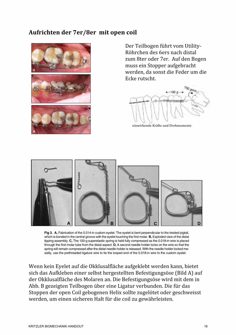
Aufrichten der 7er/8er mit open coil
Der Teilbogen führt vom Utility-‐Röhrchen des 6ers nach distal zum 8ter oder 7er. Auf den Bogen muss ein Stopper aufgebracht werden, da sonst die Feder um die Ecke rutscht.
einwirkende Kräfte und Drehmomente
Wenn kein Eyelet auf die Okklusalfläche aufgeklebt werden kann, bietet sich das Aufkleben einer selbst hergestellten Befestigungsöse (Bild A) auf der Okklusalfläche des Molaren an. Die Befestigungsöse wird mit dem in Abb. B gezeigten Teilbogen über eine Ligatur verbunden. Die für das Stoppen der open Coil gebogenen Helix sollte zugelötet oder geschweisst werden, um einen sicheren Halt für die coil zu gewährleisten.
(Fig. 3) and a 21-year-old male with an impacted lower left third molar (Fig. 4).
Variation 4: The latest step in the evolution of this procedure has been the replacement of the first-molar band by a self-ligating SPEED bracket (Fig. 5). The first-molar bracket should be placed as far gingivally as possible to avoid bond failures from occlusal interference. The main archwire termi-nates just distal to the second premolar because the SPEED self-ligating appliance does not come with buccal utility tubes. Treatment using this
220 JCO/APRIL 2012
Uprighting Mechanics for Mesially Inclined Lower Second and Third Molars
Fig. 5 Variation 4 of Versatile Molar Uprighting Mechanics (blue = sectional archwire; red = open-coil spring), with self-ligating brackets on both first and second molars.
Fig. 4 A. 21-year-old male patient with impacted lower left third molar treated with variation 3 of Versatile Uprighting technique; sectional wires bypassed bonded second-molar bracket. B. After six months of uprighting.
Fig. 3 A. 18-year-old female patient with impacted lower right third molar treated with variation 3 of Versatile Up -righting technique, using bonded double tube on first molar and self-ligating bracket on impacted molar; previ-ously bonded 3-3 lingual retainer served as additional anchorage. B. After three months of uprighting.
A
A
B
BFig. 5F2 Case 2. Force system used on right side. Lingual: open-coil spring for delivery of distal force against crown, adding to uprighting moment.
Fig. 5G1 Case 2. Appliance used on right side.
Fig. 5G2 Case 2. Appliance used on right side.
Fig. 5H1 Case 2. After treatment.
Fig. 5H2 Case 2. After treatment.
exhibited by the first molar without a low-hanging lin-gual cusp. The crown should also be rotated so thata line connecting its buccal cusps is parallel to a similarline on the first molar.
Andrews’s standard straight-wire torque prescriptionfor the maxillary second molar is !10".2 However, thisprescription is not always adequate to correct secondmolars that erupt flared buccally with excessive lingualroot torque. Slot play, long interbracket distance, andlighter square finishing arches (0.017 3 0.017 inch ina 0.0183 0.025-inch tube) routinely result in undercor-rected second molars with the !10" prescription.
Increasing the lingual crown torque to !30" reducesthe need for adding lingual crown torque during the fi-nal finishing procedures. If you use heavier finishingarches, using less torque will still work, if you compen-sate for slot play and then some. (All nominal bracketprescriptions in orthodontic catalogs are in terms ofcrown torque [angulation of the facial surface]. How-ever, the intent of a torque prescriptions or activationis to correctly achieve proper facio-lingual root position.When considering a change in a torque prescription,keep in mind that a larger plus or smaller minus meansmore lingual root movement, and a smaller plus or largerminus means more facial root movement.)
The maxillary second molar tube placement shouldroutinely produce an elevated and tipped second molar.Offset the second molar tube toward the occlusal marginto intrude the second molar in relation to the first molar.Tip the mesial aspect of the tube 3" toward the gingivato produce a slight distal tipping of the crown.
When banding the maxillary second molar, the fol-lowing steps are necessary.
1. Do not seat the band as far gingivally as you seatedthe first molar band. This will increase the verticaldifferential between the 2 teeth and tend to intrudethe second molar.
2. Seat the band a bit more mesially than distally. Thiswill accentuate the distal tipping of the crown.
3. Paying attention to Steps 1 and 2 will produce a moredefined transition from a flat occlusal plane to a curve
Fig 3. A, Fabrication of the 0.014-in custom eyelet. The eyelet is bent perpendicular to the twisted pigtail,which is bonded in the central groove with the eyelet touching the first molar.B,Exploded view of the distaltipping assembly.C, The 100-g superelastic spring is held fully compressed as the 0.018-in wire is placedthrough the first molar tube from the distal aspect. D, A second needle holder locks on the wire so that thespringwill remain compressed after the distal needle holder is released.With the needle holder lockedme-sially, use the prethreaded ligature wire to tie the looped end of the 0.018-in wire to the custom eyelet.
Fig 4. The 0.018-in stainless steel distal tipping assem-bly is tied in. The 100-g superelastic spring is severelycompressed against the first molar tube because thearm end is tied snugly to the bonded custom eyelet.
Johnson 271
American Journal of Orthodontics and Dentofacial Orthopedics August 2011 # Vol 140 # Issue 2
KRITZLER BIOMECHANIK HANDOUT
16
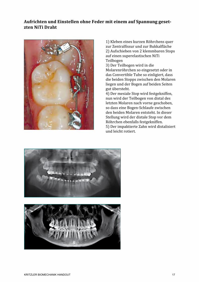
Aufrichten und Einstellen ohne Feder mit einem auf Spannung geset-‐zten NiTi Draht
1) Kleben eines kurzen Röhrchens quer zur Zentralfissur und zur Bukkalfläche 2) Aufschieben von 2 klemmbaren Stops auf einen superelastischen NiTi Teilbogen 3) Der Teilbogen wird in die Molarenröhrchen so eingesetzt oder in das Convertible Tube so einligiert, dass die beiden Stopps zwischen den Molaren liegen und der Bogen auf beiden Seiten gut übersteht. 4) Der mesiale Stop wird festgekniffen, nun wird der Teilbogen von distal des letzten Molaren nach vorne geschoben, so dass eine Bogen-‐Schlaufe zwischen den beiden Molaren entsteht. In dieser Stellung wird der distale Stop vor dem Röhrchen ebenfalls festgekniffen. 5) Der impaktierte Zahn wird distalisiert und leicht rotiert.
1A
Before Treatment
1B After Treatment
KRITZLER BIOMECHANIK HANDOUT
17
Die Abbildungen wurden folgenden Veröffentlichungen entnommen:
1. Ludwig B, Glasl B, Kinzinger G, Lisson J. Aufrichtung gekippter unterer Molaren mit Hilfe kortikaler Verankerungstechniken. Kieferorthopädie. 2010;24(1):47–54.
2. Melsen B, Fiorelli G, Bergamini A. Uprighting of Lower Molars. J Clin Orthod. 1996;30(11):640–5.
3. Nienkemper M, Pauls A, Ludwig B, Wilmes B, Drescher D. Preprosthetic Molar Uprighting Using Skeletal Anchorage. J Clin Orthod. 2013;XLVII(7):433–7.
4. Curtis A, Johnson E. Uprighting Impacted Lower Second Molars with a Stopped NiTi Arch Wire. PCSO Bull. 2010 Jan;(Winter):46–7.
5. Johnson E. Verfahren zur Einordnung impaktierter Zähne. Inf Orthod Kieferorthop. 2007 Mar;39(3):153–8.
6. Roberts WW, Chacker FM, Burstone CJ. A segmental approach to mandibular molar uprighting. Am J Orthod. 1982;81(3):177–84.
7. Sander C. Uprighting spring according to Prof. Sander. 2004 p. 1–2. www.docsander.com
8. Sander C. 3 geometries for uprighting molars. p. 1. www.docsander.com 9. Sander C. uprighting spring. 2009 p. 1–2. www.docsander.com 10. Shellhart WC, Oesterle LJ. Uprighting molars without extrusion. J Am Dent Assoc.
1999 Mar;130(3):381–5. 11. Zachrisson BU, Strobl N, Giacomo Crismani A, Bantleon H-‐P. Aufrichtung
gekippter Unterkiefermolaren: unterschiedliche Methoden im Vergleich. Inf Orthod Kieferorthop. 2007 Jun;39(2):111–5.
12. Fiorelli G. Melsen B. Biomechanics in Orthodontics 3.0, Libra Ortodonzia, Arezzo, 2015
KRITZLER BIOMECHANIK HANDOUT
18