Embed Size (px)
Citation preview
Schnittlinie!
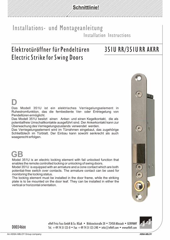
DDas Modell 351U ist ein elektrisches Verriegelungselement in Ruhestromfunktion, das die fernbediente Ver- oder Entriegelung von Pendeltüren ermöglicht.Das Modell 351U besitzt einen Anker- und einen Kegelkontakt, die als potentialfreie Umschaltkontakte ausgeführt sind. Der Ankerkontakt kann zur Überwachung des Verriegelungszustands verwendet werden. Das Verriegelungselement wird im Türrahmen eingebaut, das zugehörige Schließblech im Türblatt. Der Einbau kann sowohl senkrecht als auch waagerecht erfolgen.
Model 351U is an electric locking element with fail unlocked function that enables the remote controlled locking or unlocking of swing doors. Model 351U is equipped with an armature and a cone contact which are both potential-free switch over contacts. The armature contact can be used for monitoring the locking status. The locking element must be installed in the door frame, while the striking plate is to be mounted on the door leaf. They can be installed in either the vertical or horizontal orientation.
GB
effeff Fritz Fuss GmbH & Co. KGaA • Bildstockstraße 20 • 72458 Albstadt • GERMANYTel. +49 74 31 123-0 • Fax +49 74 31 123-240 • [email protected] • www.effeff.com
An ASSA ABLOY Group company ASSA ABLOY
D0034600
Installations- und MontageanleitungInstallation Instructions
Elektrotüröffner für Pendeltüren 351U RR/351U RR AKRRElectric Strike for Swing Doors
D
GB
Die Positionierung der Verriegelungseinheit im Türelement kann – je nach Anwendungsfall und Türkonstruktion – in einem weiten Rahmen frei gewählt werden.In Bezug auf üblicherweise an Türen auftretende Kräfte und Hebelwirkungen wird empfohlen, das Veriegelungselement in der für Schlösser üblichen Position in Höhe des Stoßgriffs anzubringen. Da die Konstruktion des Verriegelungselements jedoch eine einwandfreie Funktion in jeder Einbaulage zuläßt, sind auch andere Positionierungen möglich. So kann das Verriegelungselement beispielsweise auch oben quer liegend in der Tür eingebaut werden, so daß die prismenförmige Verriegelungsfalle nach unten in das Türblatt ausschließt. Es darf jedoch in keinem Fall im Boden eingebaut werden.
! Um zu vermeiden, daß das Verriegelungselement bei geöffneter Tür verriegelt, muß der im Schließblech montierte Kegelkontakt in die Ansteuerleitung geschaltet werden (siehe Anschlußplan). Mit der Verstellmöglichkeit des Kegelkontakts kann die Distanz zwischen Türblatt und Schließblech optimal eingestellt werden. Der Kegelkontakt ist so einzustel-len, daß dieser erst dann schließt, wenn die Falle des Verriegelungsteils bereits einge-drückt ist.
! Der Abstand zwischen Verriegelungselement und Schließblech kann mit Hilfe der mitgelieferten Distanzbleche eingestellt werden. Bei Bedarf kann das Schließblech mit diesen Distanzblechen hinterfüttert werden (siehe Einbauzeichnung).
! Der Türschließer der Tür muß so eingestellt werden, daß die Tür exakt auf die Schließposition geschlossen wird, also nicht durchpendelt.
The position of the locking element in the door can be chosen freely in a wide range depending on constructional features of the door and on the application.Referring to forces that apear usually at a door during ist normal use, it is recommended, to mount the locking element in the position where usually locks are mounted, i.e. in the height of the push bar. As the construction of the strike however allows correct function in any mounting orientation, other mounting positions are possible, too. Thus the looking element can be mounted for example in the upper horizontal part of the frame, with the prismatic latch extending downwards into the door leaf. However it will not function correctly if mounted in the floor due to moisture and dirt!
! To avoid blocking of the looking element when the door is open, the cone contact mounted in the striking plate must be connected to the wire (see wiring diagram). The cone contact offers the possibility to set the optimal distance between door leaf and striking plate. The cone contact must be set in such way that it only closes when the latch of the strike is already pushed back.
! The distance between strike and striking plate can be adjusted by placing the spacers provided under the strike plate if necessary (see mounting instructions).
! The adjustement of the door closer has to be effected in the way that the door is closed exactly to the locking position without swinging through.
Einbauhinweise
Information for Installation
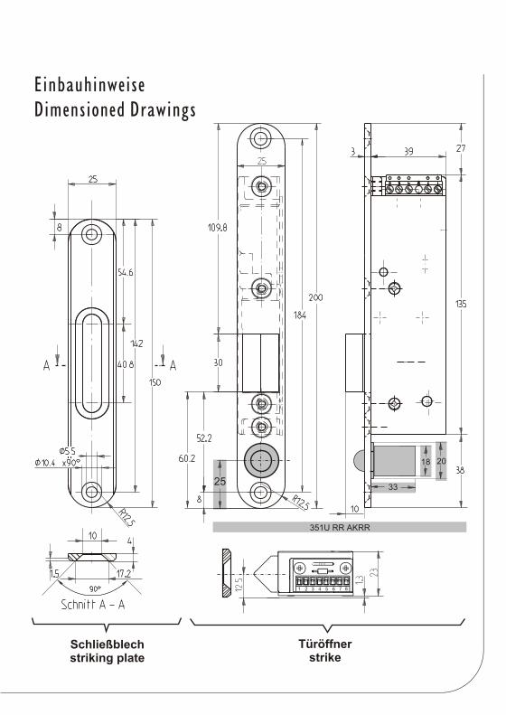
Schließblechstriking plate
Türöffnerstrike
25
18 20
33
351U RR AKRR
1 2 3 4 5 6 7 8
EinbauhinweiseDimensioned Drawings
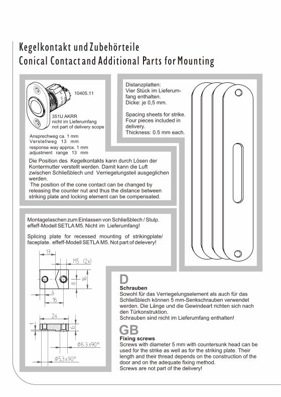
Schrauben Sowohl für das Verriegelungselement als auch für das Schließblech können 5 mm-Senkschrauben verwendet werden. Die Länge und die Gewindeart richten sich nach den Türkonstruktion.Schrauben sind nicht im Lieferumfang enthalten!
Distanzplatten:Vier Stück im Lieferum-fang enthalten.Dicke: je 0,5 mm.
Spacing sheets for strike.Four pieces included in delivery. Thickness: 0.5 mm each.
Die Position des Kegelkontakts kann durch Lösen der Kontermutter verstellt werden. Damit kann die Luft zwischen Schließblech und Verriegelungsteil ausgeglichen werden. The position of the cone contact can be changed by releasing the counter nut and thus the distance between striking plate and locking element can be compensated.
Montagelaschen zum Einlassen von Schließblech / Stulp.effeff-Modell SETLA M5. Nicht im Lieferumfang!
Splicing plate for recessed mounting of strikingplate/ faceplate. effeff-Modell SETLA M5. Not part of delevery!
Fixing screws Screws with diameter 5 mm with countersunk head can be used for the strike as well as for the striking plate. Their length and their thread depends on the construction of the door and on the adequate fixing method.Screws are not part of the delivery!
D
GB
Ansprechweg ca. 1 mmVerstellweg 13 mm
response way approx. 1 mmadjustment range 13 mm
10405.11
351U AKRRnicht im Lieferumfangnot part of delivery scope
Kegelkontakt und ZubehörteileConical Contact and Additional Parts for Mounting
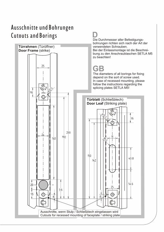
Türblatt (Schließblech)Door Leaf (Striking plate)
Türrahmen (Türöffner)Door Frame (strike)
Ausschnitte, wenn Stulp / Schließblech eingelassen wirdCutouts for recessed mounting of faceplate / striking plate
Die Durchmesser aller Befestigungs-bohrungen richten sich nach der Art der verwendeten Schrauben.Bei der Einlassmontage ist die Beschrei-bung zu den Anschraublaschen SETLA M5 zu beachten!
The diameters of all borings for fixing depend on the sort of screw used. In case of recessed mounting, please follow the instructions regarding the splicing plates SETLA M5!
D
GB
20
15
Ausschnitte und BohrungenCutouts and Borings
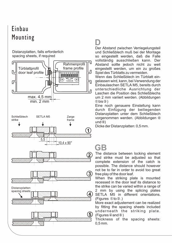
max. 4,5 mmmin. 2 mm
Rahmenprofilframe profileTürblattprofil
door leaf profile
Distanzplatten, falls erforderlichspacing sheets, if required
Der Abstand zwischen Verriegelungsteil und Schließblech muß bei der Montage so eingestellt werden, daß die Falle vollständig ausschließen kann. Der Abstand sollte jedoch nicht zu weit eingestellt werden, um ein zu großes Spiel des Türblatts zu vermeiden.Wenn das Schließblech im Türblatt ein-gelassen wird, kann, bei Verwendung der Einbaulaschen SETLA M5, bereits durch unterschiedliche Ausrichtung der Laschen die Position des Schließblechs um 2 mm variiert werden. (Abbildungen bis )Eine noch genauere Einstellung kann durch Einfügung der beiliegenden Distanzplatten unter dem Schließblech vorgenommen werden. (Abbildungen und ) Dicke der Distanzplatten: 0,5 mm.
1 3
4
5
1
2
3
4
5
The distance between locking element and strike must be adjusted so that complete extension of the catch is possible. The distance should however not be to far in order to avoid too great free play of the door leaf.When the striking plate is mounted recessed in the door leaf its distance to the strike can be varied within a range of 2 mm by using the splicing plates SETLA M5 in different orientations. (Figures to .)More exact adjustement can be realized by fitting the spacing sheets included underneath the s t r i k ing p la te . (Figures and )Thickness of the spacing sheets: 0,5 mm.
1 3
4 5
D
GB
Distanzplattenspacing sheets
Schließblechstrike
SETLA M5 Zargeframe
5,510,4 x 90°
1 2 3 4 5 6 7 8
EinbauMounting
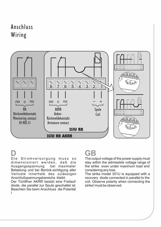
D i e S t r o m v e r s o r g u n g m u s s s o d i m e n s i o n i e r t w e r d e n , d a ß d i e Ausgangsspannung bei maximaler Belastung und bei Berück-sichtigung aller Verluste innerhalb des zulässigen Anschlußspannungsbereichs bleibt. Der Türöffner AKRR besitzt eine Freilauf-diode, die parallel zur Spule geschaltet ist. Beachten Sie beim Anschluss die Polarität !
The output voltage of the power supply must stay within the admissible voltage range of the strike even under maximum load and considering any loss.The strike model 351U is equipped with a recovery diode connected in parallel to the coil. Observe polarity when connecting the strike! must be observed.
D GB
AKRRAnker-
RückmeldekontaktArmature contact
SpuleCoil
12345678
+–nccnonccno
RRRückmeldekontaktMonitoring contact
10 405.11
351U RR
351U RR AKRR12345678
12345678
AnschlussWiring
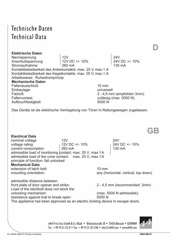
Electrical Datanominal voltage 12V 24V voltage rating 12V DC +/- 10% 24V DC +/- 10%current consumption 260 mA 130 mAadmissible load of monitoring contact: max. 25 V, max.1 Aadmissible load of the cone contact: max. 25 V, max.1 Aprinciple of function: fail unlockedMechanical Dataextension of latch bolt: 10 mmmounting orientation: any (horizontal, vertical, top down)
admissible distance betweenfront plate of door opener and strike: 2 - 4,5 mm (recommended: 3mm)Load of the latchbolt does not block the unlocking mechanism (max. 5000 N admissible).resistance against trial to break open: 5000 NThe appliance has been approved as an electric locking device in escape doors.
Elektrische DatenNennspannung 12V 24V Anschlußspannung 12V DC +/- 10% 24V DC +/- 10%Stromaufnahme 260 mA 130 mAKontaktbelastbarkeit des Ankerkontakts: max. 25 V, max.1 AKontaktbelastbarkeit des Kegelkontakts: max. 25 V, max.1 AArbeitsweise: RuhestromprinzipMechanische DatenFallenausschluß: 10 mmEinbaulage: universellFalzluft: 2 - 4,5 mm (empfohlen 3mm)Fallenvorlast: zulässig (max. 5000 N)Aufbruchfestigkeit: 5000 N
Das Geräts ist als elektrische Verriegelung von Türen in Rettungswegen zugelassen.
D
GB
Technische DatenTechnical Data
effeff Fritz Fuss GmbH & Co. KGaA • Bildstockstraße 20 • 72458 Albstadt • GERMANYTel. +49 74 31 123-0 • Fax +49 74 31 123-240 • [email protected] • www.effeff.com
An ASSA ABLOY Group company ASSA ABLOY
![Kommunikationsforum og...d8^$UYbS!NR\JQN7J$R\$4SKY=RR‘$7S_YJ$ $ $ $ $ $ $ ^k d8^8X$S!!SKQ>Y\!$R\$4SKY=RR‘$7S_YJ$ $ $ $ $ $ $ $ c] d8^8X8X$=3+,:=(&#,$/&8$N,#+2%D:=(&#,$SG(1](https://img.pdfslide.org/doc/110x75/607d507d13d7ea7b134cb094/kommunikationsforum-og-d8uybsnrjqn7jr4skyrra7syj-k.jpg)