Embed Size (px)
Citation preview
systems
Central Station
Central Station 60212 2
Inhaltsverzeichnis
1. Vorwort ................................................................. S.32. Grundlagen zur Nutzung der Central Station...... S.3 2.1. Bedienungs./Funktionselemente.......... S.3 2.2. Installation............................................. S.3 2.2.1. Batterien einsetzen/wechseln............ S.4 2.2.2. Central Station aufbauen................... S.4 2.2.3. Anschluss einer Anlage...................... S.4 2.2.4. Anschluss eines Programmiergleises. S.5 2.2.5. Direkter Anschluss einer Mobile Station. S.5 2.2.6. Anschluss Terminal 60125.................. S.5 2.2.7. Zusätzlicher externer Anschluss......... S.63. Betrieb mit der Central Station............................. S.6 3.1. Gerät einschalten/Initialisierung............. S.6 3.2.1. Aufteilung der Bedienfläche................ S.6 3.2.2.T ouchscreen bedienen........................ S.6 3.2.3. Das Funktionsprinzip der Bedienoberfläche S.6 3.2.4. Nothalt/STOP-Taste............................. S.7 3.2.5. Freigabe/GO-Taste.............................. S.7 3.3. Fahrbetrieb............................................. S.7 3.3.1. Mfx-Loks einrichten............................ S.7 3.3.2. Loks mit Märklin Delta- oder Märklin-Digitaldecoder einrichten................. S.7 3.3.3. Lok steuern......................................... S.9 3.3.4. Lokdaten ändern................................ S.11 3.3.5. Lok aus der Lokliste löschen............. S.114. Magnetartikel schalten......................................... S.12 4.1. Decoder anschließen............................ S.12 4.2. Magnetartikel einrichten/bearbeiten..... S.12 4.3. Schaltfläche einrichten......................... S.13 4.4. Magnetartikel schalten......................... S.13 4.5. Signale der 763xx-Serie programmieren.... S.145. Sonstige Einstellungen......................................... S.146. Leistungsbedarf.................................................... S.157. Zusätzliche Hinweise............................................ S.15
Table of Contents
1. Introduction............................................................. Pg.162. Basic Information for Using the Central Station.... Pg.16 2.1. Operation/ Function Elements................ Pg.16 2.2. Installation............................................. Pg.16 2.2.1. Installing/Changing Batteries.............. Pg.17 2.2.2. Setting up the central Station............. Pg.17 2.2.3. Connenctions to a Layout................... Pg.17 2.2.4. Connections for a Programming Track Pg.18 2.2.5. Direct Connections for a Mobile Station.. Pg.18 2.2.6. Connections for the 60125 Terminal.... Pg.18 2.2.7.Additional External Connections.......... Pg.183. Operation with the Central Startion....................... Pg.19 3.1.Turning the Unit on/Initializing................ Pg.19 3.2.1. Dividing up the Control Area............... Pg.19 3.2.2. Operating the Touchscreen ................ Pg.19 3.2.3. How the Control Surface Works.................. Pg.19 3.2.4. Emergency Stop/ „STOP“ Button....... Pg.20 3.2.5. Release/ „GO“ button......................... Pg.20 3.3. Operation Locomotives/ Trains.............. Pg.20 3.3.1. Setting up Mfx- Locomotives.............. Pg.20 3.3.2. Setting up Locomotives with Delta or Digital Decoders.............................. Pg.20 3.3.3. Controlling a locomotive...................... Pg.22 3.3.4. Changing Locomotive Dat................... Pg.24 3.3.5. Deleting a locomotive from the Locomotive List................................... Pg.244. Controlling.............................................................. Pg.25 4.1. Connections for Decoder....................... Pg.25 4.2. Setting up/ Processing Solenoid Accessoiries......... Pg.25 4.3. Setting up a Control Area....................... Pg.26 4.4. Controlling Solenoid Accessories........... Pg.26 4.5. Programming the 763xx Series Signals........ Pg.275. Other Settings......................................................... Pg.276. Power Requirements.............................................. Pg.287. Additional Notes .................................................... Pg.28
Central Station 602123
1. VorwortMit Märklin Systems steht inzwischen die dritte Generation an Märklin-Mehrzugsystemen bereit. Die wichtigste Komponente stellt dabei die Central Station dar, die für die Erzeugung der richtigen Steuerdaten verantwortlich ist, die Koordination der angeschlos-senen Geräte durchführt und außerdem noch eine komfortable und übersichtliche Bedienungsoberfläche bietet. Ein einwandfreier Betrieb ist bei diesem komplexen System nur sicher gestellt, wenn Sie ausschließlich auf die geprüften und getesteten Märklin-Sys-temkomponenten zurückgreifen. Bei der Verwendung irgendwelcher Fremdprodukte entfällt daher jede Herstellergarantie von Märklin. Für Schäden, die bei der Verwendung von Fremdprodukten auftreten, ist daher der Betreiber verantwortlich.
Halten Sie sich beim Anschluss der Anlage an die vorgestellten Tech-niken und Prinzipien aus dieser Anleitung. Der Einsatz von anderen Schaltungen kann leicht zu Beschädigungen an den elektronischen Komponenten führen. Verzichten Sie daher lieber auf „teure“ Experi-mente.
Die Central Station ist kein Spielzeug. Stellen Sie sicher, dass dieses Gerät auch von Kindern nur als Steuerungsgerät für die Modelleisen-bahn genutzt wird.
Wir wünschen Ihnen viel Freude beim Einsatz der Central Station an Ihrer Modelleisenbahnanlage.
Ihr Märklin Service-Team
2. Grundlagen zur Nutzung der Central Station
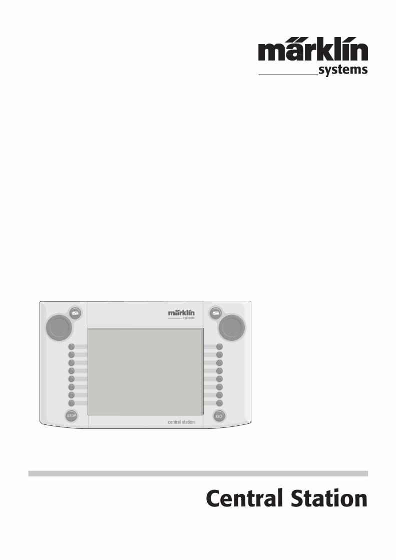
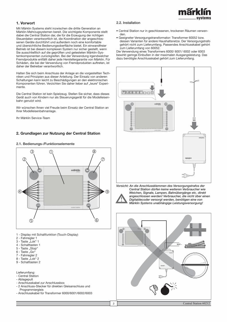
2.1. Bedienungs-/Funktionselemente
1 - Display mit Schaltfunktion (Touch-Display)2 - Fahrregler 13 - Taste „Lok“ 14 - Schalttasten 15 - Taste „Stop“6 - Taste „Go“7 - Fahrregler 28 - Taste „Lok“ 29 - Schalttasten 2
Lieferumfang:- Central Station- Ablagepult- Anschlusskabel zur Anschlussbox- 2 Anschluss-Stecker für direkten Gleisanschluss und
Programmiergleis- Anschlusskabel für Transformer 6000/6001/6002/6003
2.2. Installation
• Central Station nur in geschlossenen, trockenen Räumen verwen-den.
• Geeigneter Versorgungstransformator: Transformer 60052 bzw. dessen Varianten für andere Haushaltsnetze. Der Versorgungstrafo gehört nicht zum Lieferumfang. Passendes Anschlusskabel gehört zum Lieferumfang von 60052.
Die Verwendung eines Transformers 6000/ 6001/ 6002 oder 6003 bewirkt geringe Einbußen in der maximalen Ausgangsleistung. Das dazu benötigte Anschlusskabel gehört zum Lieferumfang.
Vorsicht: An die Anschlussklemmen des Versorgungstrafos der Central Station dürfen keine weiteren Verbraucher wie Weichen, Signale, Lampen, Bahnübergänge etc. direkt angeschlossen werden! Verbraucher, die nicht über einen Digitaldecoder versorgt werden, benötigen eine von Märklin Systems unabhängige Leistungsversorgung!
�
�
�
�
� �
�
�
�
16 V ~
��
!
Central Station 60212 4
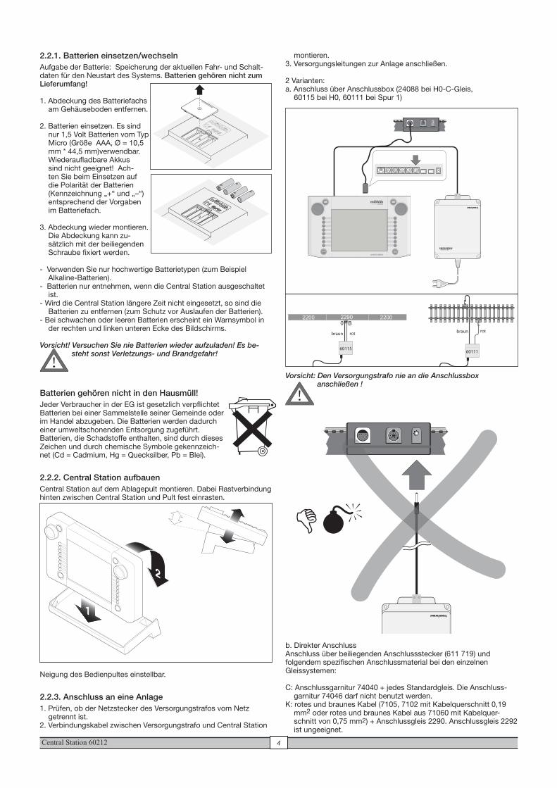
2.2.1. Batterien einsetzen/wechselnAufgabe der Batterie: Speicherung der aktuellen Fahr- und Schalt-daten für den Neustart des Systems. Batterien gehören nicht zum Lieferumfang!
1. Abdeckung des Batteriefachs am Gehäuseboden entfernen.
2. Batterien einsetzen. Es sind nur 1,5 Volt Batterien vom Typ Micro (Größe AAA, Ø = 10,5 mm * 44,5 mm)verwendbar. Wiederaufladbare Akkus sind nicht geeignet! Ach-ten Sie beim Einsetzen auf die Polarität der Batterien (Kennzeichnung „+“ und „–“) entsprechend der Vorgaben im Batteriefach.
3. Abdeckung wieder montieren. Die Abdeckung kann zu-sätzlich mit der beiliegenden Schraube fixiert werden.
- Verwenden Sie nur hochwertige Batterietypen (zum Beispiel Alkaline-Batterien).
- Batterien nur entnehmen, wenn die Central Station ausgeschaltet ist.
- Wird die Central Station längere Zeit nicht eingesetzt, so sind die Batterien zu entfernen (zum Schutz vor Auslaufen der Batterien).
- Bei schwachen oder leeren Batterien erscheint ein Warnsymbol in der rechten und linken unteren Ecke des Bildschirms.
Vorsicht! Versuchen Sie nie Batterien wieder aufzuladen! Es be-steht sonst Verletzungs- und Brandgefahr!
Batterien gehören nicht in den Hausmüll!Jeder Verbraucher in der EG ist gesetzlich verpflichtet Batterien bei einer Sammelstelle seiner Gemeinde oder im Handel abzugeben. Die Batterien werden dadurch einer umweltschonenden Entsorgung zugeführt.Batterien, die Schadstoffe enthalten, sind durch dieses Zeichen und durch chemische Symbole gekennzeich-net (Cd = Cadmium, Hg = Quecksilber, Pb = Blei).
2.2.2. Central Station aufbauenCentral Station auf dem Ablagepult montieren. Dabei Rastverbindung hinten zwischen Central Station und Pult fest einrasten.
Neigung des Bedienpultes einstellbar.
2.2.3. Anschluss an eine Anlage1. Prüfen, ob der Netzstecker des Versorgungstrafos vom Netz
getrennt ist.2. Verbindungskabel zwischen Versorgungstrafo und Central Station
Titel: »Batteriefach öffnen«Seite Nr: 6Datei: 6 Batteriefach öffnen.AIDatei-Typ: Adobe Illustrator 10.0Anleitung: 610 571 »Centralstation«Artikel-Nr.: 60212Datum: 22.11.2004
montieren.3. Versorgungsleitungen zur Anlage anschließen.
2 Varianten: a. Anschluss über Anschlussbox (24088 bei H0-C-Gleis,
60115 bei H0, 60111 bei Spur 1)
Vorsicht: Den Versorgungstrafo nie an die Anschlussbox anschließen !
b. Direkter Anschluss Anschluss über beiliegenden Anschlussstecker (611 719) und folgendem spezifischen Anschlussmaterial bei den einzelnen Gleissystemen:
C: Anschlussgarnitur 74040 + jedes Standardgleis. Die Anschluss-garnitur 74046 darf nicht benutzt werden.
K: rotes und braunes Kabel (7105, 7102 mit Kabelquerschnitt 0,19 mm2 oder rotes und braunes Kabel aus 71060 mit Kabelquer-schnitt von 0,75 mm2) + Anschlussgleis 2290. Anschlussgleis 2292 ist ungeeignet.
6011560111
rot braunrot braun
!
!
Central Station 602125
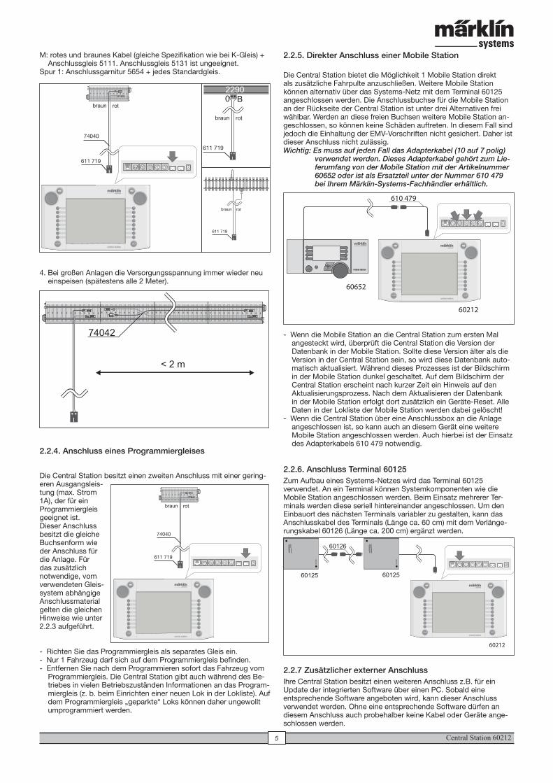
M: rotes und braunes Kabel (gleiche Spezifikation wie bei K-Gleis) + Anschlussgleis 5111. Anschlussgleis 5131 ist ungeeignet.
Spur 1: Anschlussgarnitur 5654 + jedes Standardgleis.
4. Bei großen Anlagen die Versorgungsspannung immer wieder neu einspeisen (spätestens alle 2 Meter).
2.2.4. Anschluss eines Programmiergleises
Die Central Station besitzt einen zweiten Anschluss mit einer gering-eren Ausgangsleis-tung (max. Strom 1A), der für ein Programmiergleis geeignet ist. Dieser Anschluss besitzt die gleiche Buchsenform wie der Anschluss für die Anlage. Für das zusätzlich notwendige, vom verwendeten Gleis-system abhängige Anschlussmaterial gelten die gleichen Hinweise wie unter 2.2.3 aufgeführt.
- Richten Sie das Programmiergleis als separates Gleis ein.- Nur 1 Fahrzeug darf sich auf dem Programmiergleis befinden.- Entfernen Sie nach dem Programmieren sofort das Fahrzeug vom
Programmiergleis. Die Central Station gibt auch während des Be-triebes in vielen Betriebszuständen Informationen an das Program-miergleis (z. b. beim Einrichten einer neuen Lok in der Lokliste). Auf dem Programmiergleis „geparkte“ Loks können daher ungewollt umprogrammiert werden.
611 719
74040
rotbraun
611 719
rotbraun
611 719
rotbraun
< 2 m
74042
611 719
74040
rotbraun
2.2.5. Direkter Anschluss einer Mobile Station
Die Central Station bietet die Möglichkeit 1 Mobile Station direkt als zusätzliche Fahrpulte anzuschließen. Weitere Mobile Station können alternativ über das Systems-Netz mit dem Terminal 60125 angeschlossen werden. Die Anschlussbuchse für die Mobile Station an der Rückseite der Central Station ist unter drei Alternativen frei wählbar. Werden an diese freien Buchsen weitere Mobile Station an-geschlossen, so können keine Schäden auftreten. In diesem Fall sind jedoch die Einhaltung der EMV-Vorschriften nicht gesichert. Daher ist dieser Anschluss nicht zulässig.Wichtig: Es muss auf jeden Fall das Adapterkabel (10 auf 7 polig)
verwendet werden. Dieses Adapterkabel gehört zum Lie-ferumfang von der Mobile Station mit der Artikelnummer 60652 oder ist als Ersatzteil unter der Nummer 610 479 bei Ihrem Märklin-Systems-Fachhändler erhältlich.
- Wenn die Mobile Station an die Central Station zum ersten Mal angesteckt wird, überprüft die Central Station die Version der Datenbank in der Mobile Station. Sollte diese Version älter als die Version in der Central Station sein, so wird diese Datenbank auto-matisch aktualisiert. Während dieses Prozesses ist der Bildschirm in der Mobile Station dunkel geschaltet. Auf dem Bildschirm der Central Station erscheint nach kurzer Zeit ein Hinweis auf den Aktualisierungsprozess. Nach dem Aktualisieren der Datenbank in der Mobile Station erfolgt dort zusätzlich ein Geräte-Reset. Alle Daten in der Lokliste der Mobile Station werden dabei gelöscht!
- Wenn die Central Station über eine Anschlussbox an die Anlage angeschlossen ist, so kann auch an diesem Gerät eine weitere Mobile Station angeschlossen werden. Auch hierbei ist der Einsatz des Adapterkabels 610 479 notwendig.
2.2.6. Anschluss Terminal 60125Zum Aufbau eines Systems-Netzes wird das Terminal 60125 verwendet. An ein Terminal können Systemkomponenten wie die Mobile Station angeschlossen werden. Beim Einsatz mehrerer Ter-minals werden diese seriell hintereinander angeschlossen. Um den Einbauort des nächsten Terminals variabler zu gestalten, kann das Anschlusskabel des Terminals (Länge ca. 60 cm) mit dem Verlänge-rungskabel 60126 (Länge ca. 200 cm) ergänzt werden.
2.2.7 Zusätzlicher externer AnschlussIhre Central Station besitzt einen weiteren Anschluss z.B. für ein Update der integrierten Software über einen PC. Sobald eine entsprechende Software angeboten wird, kann dieser Anschluss verwendet werden. Ohne eine entsprechende Software dürfen an diesem Anschluss auch probehalber keine Kabel oder Geräte ange-schlossen werden.
STOP
610 479
60652
60212
60212
term
inal
term
inal
60126
60125 60125
Central Station 60212 6
Vorsicht! Beim Entfernen eines Anschlusskabels zum PC muss vor dem Herausziehen des Kabels die Rastnase gedrückt werden. Diese befindet sich aber direkt unter dem Boden der Central Station. Lösen Sie diese Rastverbindung da-her vorsichtig z. B. mit einem flachen Schraubendreher.
3. Betrieb mit der Central Station3.1. Gerät einschalten /InitialisierungDas Gerät muss wie im Kapitel 2 beschrieben auf die Gegebenheiten bei Ihrer Modellbahnanlage abgestimmt aufgebaut sein. Stecken Sie jetzt den Netzstecker des Versorgungstrafos für die Central Station in die Netzsteckdose.
Vorsicht: Überprüfen Sie unbedingt, ob der Transformator auch für die Netzspannung in Ihrem Haushalt geeignet ist. Auf dem Typenschild auf der Unterseite des Transformators finden Sie die entsprechenden Angaben. z.B. Transformer 60 VA (60052): 230 V~/50 Hz
Transformer 60 VA (60055): 120 V~/60 Hz
Vorsicht: Märklin-Transformatoren dürfen nur in trockenen, ge-schlossenen Räumen eingesetzt werden. Die Central Station kann im Außenbereich (z.B. für eine Spur 1 Gartenbahn) nur dann eingesetzt werden, wenn sie vor Feuchtigkeit und vor extremen Temperaturen geschützt montiert ist. Belassen Sie die Central Station in diesem Fall nur während des Spielbetriebs im Außen-bereich. Die Central Station darf weder Regen, direkter Sonneinstrahlung noch Temperaturen unter 10° Celsius oder über 30° Celsius ausgesetzt werden.
Tipp: Verwenden Sie für die Netzstecker der Versorgungstrafos eine Steckerleiste mit Ein-/Ausschalter zum gemeinsamen Einschalten der Komponenten. Um die Central Station vor Überspannungen durch Blitzschlag zu sichern ist der Einsatz einer Schutzeinrichtung zwischen Haushalts-netz und Netzstecker bzw. die Verwendung einer Steckdosenleiste mit integriertem Überspannungsschutz zu empfehlen.
Sobald der Transformator die Central Station mit ausreichender Leis-tung versorgt, beginnt bei der Central Station die sogenannte Initiali-sierungsphase. Diese kann auch je nach der Menge der einzurichten-den Daten länger als 1 bis 2 Minuten dauern. Der Ablauf der Initialisierungsphase wird nach einigen Sekunden durch das Einschalten der Bildschirmbeleuchtung und kurz danach mit einem im unteren Bereich des Bild-schirms hin- und herlaufen-den Quadrats dokumentiert.
Hinweis: Gerade beim ersten Einschalten kann die Initialisierungs-phase etwas länger dauern. Dabei kann es auch dazu kommen, dass die Bildschirmbeleuchtung ausschaltet. Diese wird jedoch mit dem Beenden der Initialisierung automatisch wieder eingeschaltet.
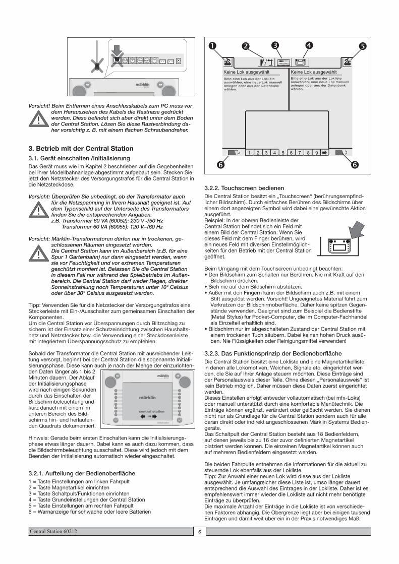
3.2.1. Aufteilung der Bedienoberfläche1 = Taste Einstellungen am linken Fahrpult2 = Taste Magnetartikel einrichten3 = Taste Schaltpult/Funktionen einrichten4 = Taste Grundeinstellungen der Central Station5 = Taste Einstellungen am rechten Fahrpult6 = Warnanzeige für schwache oder leere Batterien
!
central station
1 2 3 4 5 6 7 8 9
Keine Lok ausgewählt Keine Lok ausgewähltBitte eine Lok aus der Loklisteauswählen, eine neue Lok manuell anlegen oder aus der Datenbankwählen.
Bitte eine Lok aus der Loklisteauswählen, eine neue Lok manuell anlegen oder aus der Datenbankwählen.
� � � � �
� �
3.2.2. Touchscreen bedienenDie Central Station besitzt ein „Touchscreen“ (berührungsempfind-licher Bildschirm). Durch einfaches Berühren des Bildschirms über einem dort angezeigten Symbol wird dabei eine gewünschte Aktion ausgeführt. Beispiel: In der oberen Bedienleiste der Central Station befindet sich ein Feld mit einem Bild der Central Station. Wenn Sie dieses Feld mit dem Finger berühren, wird ein neues Feld mit diversen Einstellmöglich-keiten für den Betrieb mit der Central Station geöffnet.
Beim Umgang mit dem Touchscreen unbedingt beachten:• Den Bildschirm zum Schalten nur Berühren. Nie mit Kraft auf den
Bildschirm drücken. • Sich nie auf dem Bildschirm abstützen.• Außer mit den Fingern kann der Bildschirm auch z.B. mit einem
Stift ausgelöst werden. Vorsicht! Ungeeignetes Material führt zum Verkratzen der Bildschirmoberfläche. Daher keine spitzen Gegen-stände verwenden. Geeignet sind zum Beispiel die Bedienstifte (Metal Stylus) für Pocket-Computer, die im Computer-Fachhandel als Einzelteil erhältlich sind.
• Bildschirm nur im abgeschalteten Zustand der Central Station mit einem trockenen Tuch säubern. Dabei keinen hohen Druck ausü-ben. Nie Flüssigkeiten oder Reinigungsmittel verwenden!
3.2.3. Das Funktionsprinzip der Bedienoberfläche Die Central Station besitzt eine Lokliste und eine Magnetartikelliste, in denen alle Lokomotiven, Weichen, Signale etc. eingerichtet wer-den, die Sie auf Ihrer Anlage steuern möchten. Diese Einträge sind der Personalausweis dieser Teile. Ohne diesen „Personalausweis“ ist kein Betrieb möglich. Daher müssen diese Daten zuerst eingerichtet werden. Dieses Einstellen erfolgt entweder vollautomatisch (bei mfx-Loks) oder manuell unterstützt durch eine komfortable Menütechnik. Die Einträge können ergänzt, verändert oder gelöscht werden. Sie dienen nicht nur als Grundlage für die Central Station sondern auch für alle daran direkt oder indirekt angeschlossenen Märklin Systems Bedien-geräte. Das Schaltpult der Central Station besteht aus 18 Bedienfeldern, auf denen jeweils bis zu 16 der zuvor definierten Magnetartikel platziert werden können. Die einzelnen Magnetartikel können auch auf mehreren Bedienfeldern eingesetzt werden.
Die beiden Fahrpulte entnehmen die Informationen für die aktuell zu steuernde Lok ebenfalls aus der Lokliste.Tipp: Zur Anwahl einer neuen Lok wird diese aus der Lokliste ausgewählt. Je umfangreicher diese Liste ist, umso länger dauert entsprechend die Auswahl des Eintrages in der Lokliste. Daher ist es empfehlenswert immer wieder die Lokliste auf nicht mehr benötigte Einträge zu überprüfen.Die maximale Anzahl der Einträge in die Lokliste ist von verschiede-nen Faktoren abhängig. Die Obergrenze liegt aber bei einigen tausend Einträgen und damit weit über ein in der Praxis notwendiges Maß.
!
60212
!
Central Station 602127
3.3.2. Loks mit Märklin Delta- oder Märklin-Digitaldecoder einrichtenDie Central Station ist in der Lage auch die verschiedenen Märklin Delta- oder Digital-Decodergenerationen zu steuern, die für den Be-trieb mit Märklin Delta oder Märklin Digital (sowohl Central Unit 6020 als auch Control Unit 6021 und deren Varianten) konzipiert sind.
Die nachfolgenden Schritte können sowohl am rechten als auch am linken Fahrgerät durchgeführt werden. Exemplarisch wird die Bedie-nung nachfolgend am linken Fahrgerät demonstriert.
Menütaste in der linken oberen Ecke des Displays drücken. Es erscheint nebenstehendes Auswahlmenü auf dem Display. Der Pfeil in der Zeile „Neue Lok“ deutet an, dass sich weitere Auswahl-menüs bei Auswahl dieser Zeile öffnen. Zur Auswahl der verschiedenen Unter-menüs gibt es zwei unterschiedliche Vorgehensweisen:
a: Direkte Anwahl durch Berühren des Bildschirmes an der jeweiligen Textzeile.
b: Drehen am linken Fahrregler des Fahrgerätes. Der schwarz mar-kierende Balken wandert dabei von Zeile zu Zeile. Durch Drücken auf den Fahrregler wird das Untermenü aktiviert, auf dem der schwarze Balken gerade steht.
Wählen Sie die Zeile „Neue Lok“ aus und aktivieren Sie das Unter- menü. Es erscheinen zwei neue Wahlfelder „Manuell anlegen“ und „Aus Datenbank“.
Manuell anlegen - Der Eintrag in die Lokliste (Name, Adresse etc.) wird komplett vom Bediener erstellt.
Aus Datenbank - Beim Erstellen der Lokdaten wird auf eine in der Central Station integrierten Datenbank mit den Werkdaten vieler früherer Märklin Artikel zurückgegriffen.
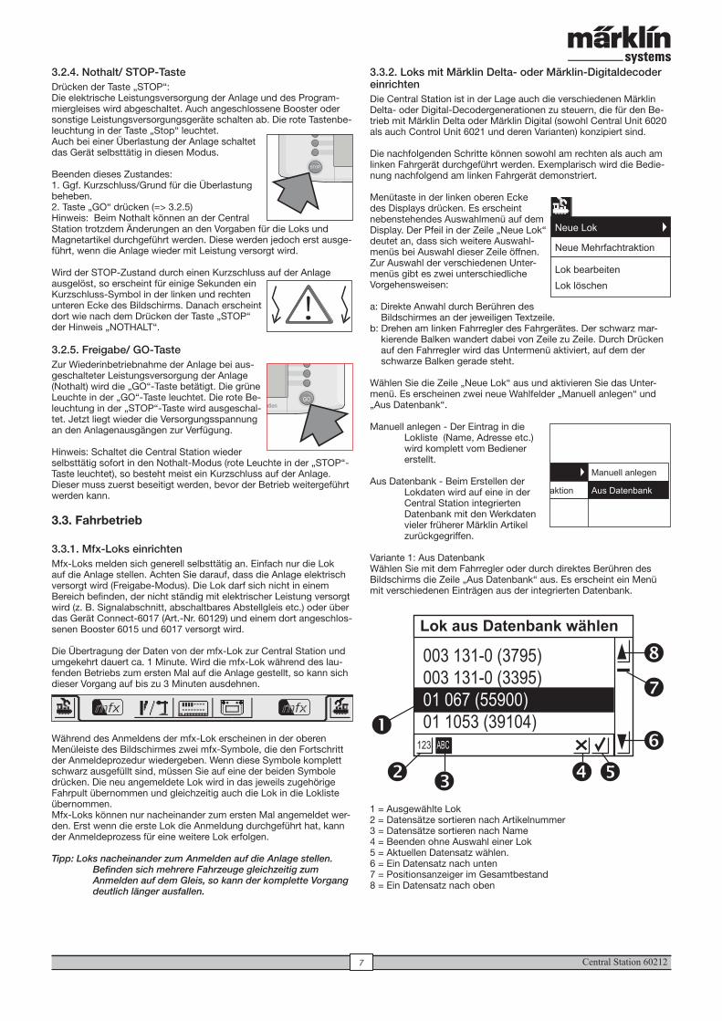
Variante 1: Aus DatenbankWählen Sie mit dem Fahrregler oder durch direktes Berühren des Bildschirms die Zeile „Aus Datenbank“ aus. Es erscheint ein Menü mit verschiedenen Einträgen aus der integrierten Datenbank.
1 = Ausgewählte Lok2 = Datensätze sortieren nach Artikelnummer3 = Datensätze sortieren nach Name4 = Beenden ohne Auswahl einer Lok5 = Aktuellen Datensatz wählen.6 = Ein Datensatz nach unten7 = Positionsanzeiger im Gesamtbestand8 = Ein Datensatz nach oben
3.2.4. Nothalt/ STOP-TasteDrücken der Taste „STOP“: Die elektrische Leistungsversorgung der Anlage und des Program-miergleises wird abgeschaltet. Auch angeschlossene Booster oder sonstige Leistungsversorgungsgeräte schalten ab. Die rote Tastenbe-leuchtung in der Taste „Stop“ leuchtet. Auch bei einer Überlastung der Anlage schaltet das Gerät selbsttätig in diesen Modus.
Beenden dieses Zustandes:1. Ggf. Kurzschluss/Grund für die Überlastung beheben.2. Taste „GO“ drücken (=> 3.2.5)Hinweis: Beim Nothalt können an der Central Station trotzdem Änderungen an den Vorgaben für die Loks und Magnetartikel durchgeführt werden. Diese werden jedoch erst ausge-führt, wenn die Anlage wieder mit Leistung versorgt wird.
Wird der STOP-Zustand durch einen Kurzschluss auf der Anlage ausgelöst, so erscheint für einige Sekunden ein Kurzschluss-Symbol in der linken und rechten unteren Ecke des Bildschirms. Danach erscheint dort wie nach dem Drücken der Taste „STOP“ der Hinweis „NOTHALT“.
3.2.5. Freigabe/ GO-TasteZur Wiederinbetriebnahme der Anlage bei aus-geschalteter Leistungsversorgung der Anlage (Nothalt) wird die „GO“-Taste betätigt. Die grüne Leuchte in der „GO“-Taste leuchtet. Die rote Be-leuchtung in der „STOP“-Taste wird ausgeschal-tet. Jetzt liegt wieder die Versorgungsspannung an den Anlagenausgängen zur Verfügung.
Hinweis: Schaltet die Central Station wieder selbsttätig sofort in den Nothalt-Modus (rote Leuchte in der „STOP“-Taste leuchtet), so besteht meist ein Kurzschluss auf der Anlage. Dieser muss zuerst beseitigt werden, bevor der Betrieb weitergeführt werden kann.
3.3. Fahrbetrieb
3.3.1. Mfx-Loks einrichten Mfx-Loks melden sich generell selbsttätig an. Einfach nur die Lok auf die Anlage stellen. Achten Sie darauf, dass die Anlage elektrisch versorgt wird (Freigabe-Modus). Die Lok darf sich nicht in einem Bereich befinden, der nicht ständig mit elektrischer Leistung versorgt wird (z. B. Signalabschnitt, abschaltbares Abstellgleis etc.) oder über das Gerät Connect-6017 (Art.-Nr. 60129) und einem dort angeschlos-senen Booster 6015 und 6017 versorgt wird.
Die Übertragung der Daten von der mfx-Lok zur Central Station und umgekehrt dauert ca. 1 Minute. Wird die mfx-Lok während des lau-fenden Betriebs zum ersten Mal auf die Anlage gestellt, so kann sich dieser Vorgang auf bis zu 3 Minuten ausdehnen.
Während des Anmeldens der mfx-Lok erscheinen in der oberen Menüleiste des Bildschirmes zwei mfx-Symbole, die den Fortschritt der Anmeldeprozedur wiedergeben. Wenn diese Symbole komplett schwarz ausgefüllt sind, müssen Sie auf eine der beiden Symbole drücken. Die neu angemeldete Lok wird in das jeweils zugehörige Fahrpult übernommen und gleichzeitig auch die Lok in die Lokliste übernommen. Mfx-Loks können nur nacheinander zum ersten Mal angemeldet wer-den. Erst wenn die erste Lok die Anmeldung durchgeführt hat, kann der Anmeldeprozess für eine weitere Lok erfolgen.
Tipp: Loks nacheinander zum Anmelden auf die Anlage stellen. Befinden sich mehrere Fahrzeuge gleichzeitig zum Anmelden auf dem Gleis, so kann der komplette Vorgang deutlich länger ausfallen.
GO
Lok aus Datenbank wählen
123 ABC
003 131-0 (3795)
003 131-0 (3395)
01 067 (55900)
01 1053 (39104)
� � ��
�
�
�
�
!
Neue Lok
Neue Mehrfachtraktion
Lok bearbeiten
Lok löschen
Neue Lok
Neue Mehrfachtraktion
Lok bearbeiten
Lok löschen
Manuell anlegen
Aus Datenbank
mfx mfx
Central Station 60212 8
Zur Auswahl des Datensatzes:Entweder durch Drehen am Fahrregler den Auswahlbalken (1) nach oben oder unten bewegen und durch Drücken auf den Fahrregler die gewünschte Lok auswählen. Alternativ kann durch Drücken auf die Pfeiltasten (6 oder 8) durch die Datensatzliste navigiert werden. Durch Betätigen der Schaltfläche mit dem Haken (5) wird der gerade ausgewählte Datensatz ausgewählt. Durch Berühren der Schaltfläche mit dem Kreuz (4) kann der Vorgang ohne Auswahl einer Lok abgebrochen werden.Die Loks in der Datenbank können nach zwei verschiedenen Kriterien sortiert werden. Entweder über die Märklin-Artikelnummer (Taste 2 berühren) oder über den von Märklin vorgeschlagenen Namen (Taste 3 berühren). Tipp: Der Name ergibt sich bei den Produkten häufig aus der Baureihennummer oder aus einem geläufigen Spitznamen des Vorbildes.Durch Drücken eines Buchstabens oder einer Zahl auf der im unteren Teil des Bildschirms dargestellten Tastatur springt die Anzeige zu dem Datensatz, der als erstes mit diesem Zeichen beginnt. Beispiel: Die Liste ist nach Namen sortiert. Durch Drücken auf die Taste „8“ wird zu den verschiedenen Datensätze der Baureihe 80 gesprungen, da diese als erstes mit der Ziffer„8“ beginnen.
Nach der Auswahl des Datensatzes wird dieser direkt in das Fahr-gerät übernommen. Sollen Lokdaten wie Name, Funktionsbelegung oder Adresse etc. geändert werden, so beachten Sie die Hinweise im Kapitel 3.3.4.
Hinweis: Die Central Station akzeptiert im Gegensatz zur Mobile Station auch mehrere Einträge in die Lokliste mit gleicher Adresse! Es können jedoch keine Loks mit identischer Adresse gleichzeitig gesteuert werden. Es erfolgt in diesem Fall im Fahrpult eine entsprechende Anzeige. Dies gilt auch für Loks mit einer Folgeadresse (Modell mit zwei Adressen).
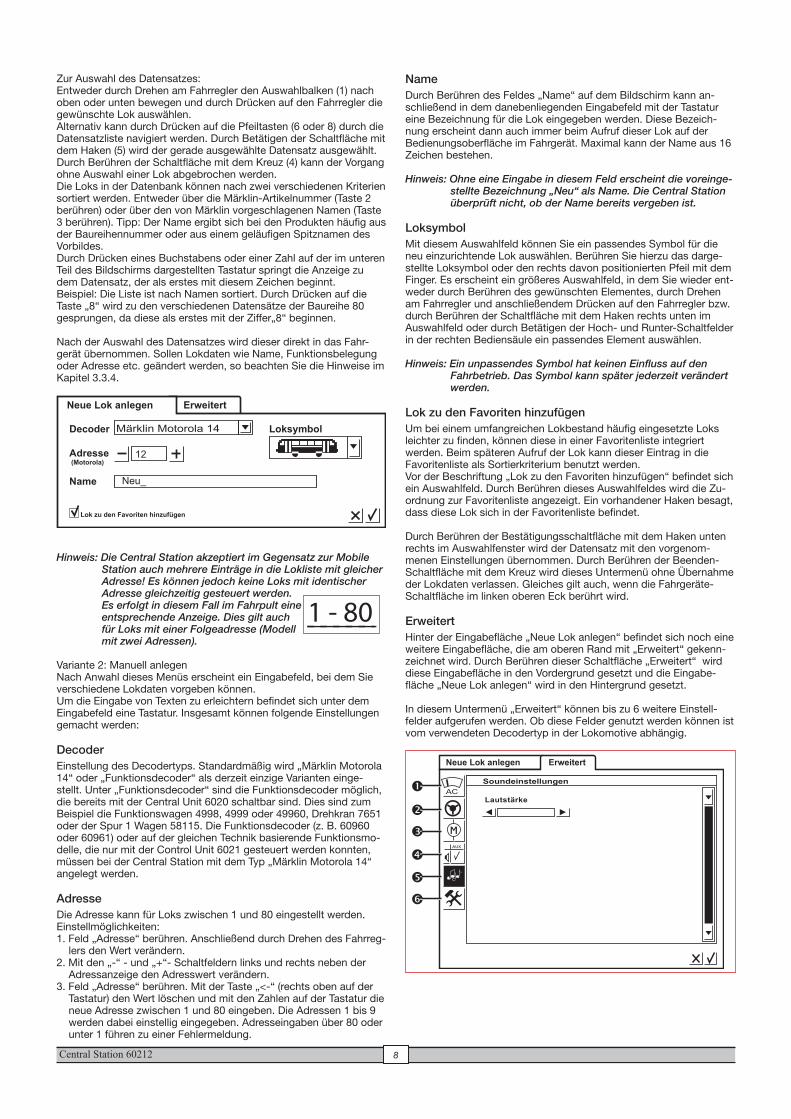
Variante 2: Manuell anlegenNach Anwahl dieses Menüs erscheint ein Eingabefeld, bei dem Sie verschiedene Lokdaten vorgeben können. Um die Eingabe von Texten zu erleichtern befindet sich unter dem Eingabefeld eine Tastatur. Insgesamt können folgende Einstellungen gemacht werden:
DecoderEinstellung des Decodertyps. Standardmäßig wird „Märklin Motorola 14“ oder „Funktionsdecoder“ als derzeit einzige Varianten einge-stellt. Unter „Funktionsdecoder“ sind die Funktionsdecoder möglich, die bereits mit der Central Unit 6020 schaltbar sind. Dies sind zum Beispiel die Funktionswagen 4998, 4999 oder 49960, Drehkran 7651 oder der Spur 1 Wagen 58115. Die Funktionsdecoder (z. B. 60960 oder 60961) oder auf der gleichen Technik basierende Funktionsmo-delle, die nur mit der Control Unit 6021 gesteuert werden konnten, müssen bei der Central Station mit dem Typ „Märklin Motorola 14“ angelegt werden. Adresse Die Adresse kann für Loks zwischen 1 und 80 eingestellt werden. Einstellmöglichkeiten:1. Feld „Adresse“ berühren. Anschließend durch Drehen des Fahrreg-
lers den Wert verändern.2. Mit den „-“ - und „+“- Schaltfeldern links und rechts neben der
Adressanzeige den Adresswert verändern.3. Feld „Adresse“ berühren. Mit der Taste „<-“ (rechts oben auf der
Tastatur) den Wert löschen und mit den Zahlen auf der Tastatur die neue Adresse zwischen 1 und 80 eingeben. Die Adressen 1 bis 9 werden dabei einstellig eingegeben. Adresseingaben über 80 oder unter 1 führen zu einer Fehlermeldung.
NameDurch Berühren des Feldes „Name“ auf dem Bildschirm kann an-schließend in dem danebenliegenden Eingabefeld mit der Tastatur eine Bezeichnung für die Lok eingegeben werden. Diese Bezeich-nung erscheint dann auch immer beim Aufruf dieser Lok auf der Bedienungsoberfläche im Fahrgerät. Maximal kann der Name aus 16 Zeichen bestehen.
Hinweis: Ohne eine Eingabe in diesem Feld erscheint die voreinge-stellte Bezeichnung „Neu“ als Name. Die Central Station überprüft nicht, ob der Name bereits vergeben ist.
LoksymbolMit diesem Auswahlfeld können Sie ein passendes Symbol für die neu einzurichtende Lok auswählen. Berühren Sie hierzu das darge-stellte Loksymbol oder den rechts davon positionierten Pfeil mit dem Finger. Es erscheint ein größeres Auswahlfeld, in dem Sie wieder ent-weder durch Berühren des gewünschten Elementes, durch Drehen am Fahrregler und anschließendem Drücken auf den Fahrregler bzw. durch Berühren der Schaltfläche mit dem Haken rechts unten im Auswahlfeld oder durch Betätigen der Hoch- und Runter-Schaltfelder in der rechten Bediensäule ein passendes Element auswählen.
Hinweis: Ein unpassendes Symbol hat keinen Einfluss auf den Fahrbetrieb. Das Symbol kann später jederzeit verändert werden.
Lok zu den Favoriten hinzufügenUm bei einem umfangreichen Lokbestand häufig eingesetzte Loks leichter zu finden, können diese in einer Favoritenliste integriert werden. Beim späteren Aufruf der Lok kann dieser Eintrag in die Favoritenliste als Sortierkriterium benutzt werden.Vor der Beschriftung „Lok zu den Favoriten hinzufügen“ befindet sich ein Auswahlfeld. Durch Berühren dieses Auswahlfeldes wird die Zu-ordnung zur Favoritenliste angezeigt. Ein vorhandener Haken besagt, dass diese Lok sich in der Favoritenliste befindet.
Durch Berühren der Bestätigungsschaltfläche mit dem Haken unten rechts im Auswahlfenster wird der Datensatz mit den vorgenom-menen Einstellungen übernommen. Durch Berühren der Beenden-Schaltfläche mit dem Kreuz wird dieses Untermenü ohne Übernahme der Lokdaten verlassen. Gleiches gilt auch, wenn die Fahrgeräte-Schaltfläche im linken oberen Eck berührt wird.
Erweitert Hinter der Eingabefläche „Neue Lok anlegen“ befindet sich noch eine weitere Eingabefläche, die am oberen Rand mit „Erweitert“ gekenn-zeichnet wird. Durch Berühren dieser Schaltfläche „Erweitert“ wird diese Eingabefläche in den Vordergrund gesetzt und die Eingabe- fläche „Neue Lok anlegen“ wird in den Hintergrund gesetzt.
In diesem Untermenü „Erweitert“ können bis zu 6 weitere Einstell- felder aufgerufen werden. Ob diese Felder genutzt werden können ist vom verwendeten Decodertyp in der Lokomotive abhängig.
Neue Lok anlegen Erweitert
Decoder Loksymbol
Adresse (Motorola)
Name
Lok zu den Favoriten hinzufügen
Neu_
12
Märklin Motorola 14
1 - 80
Neue Lok anlegen Erweitert
Soundeinstellungen
AC
MAUX
�
�
�
�
�
�
Lautstärke
Central Station 602129
Hinweis: Nach einer Änderung der Funktionszuordnung müssen auch die Darstellungen der Funktionen auf dem Bild-schirm überprüft werden. (=> 3.3.4. Funktionssymbole anpassen)
5 = SoundeinstellungenBei bestimmten Decodern mit eingebautem Soundmodul können hier verschiedene Parameter eingestellt werden. Am interessantesten ist die Einstellung der Lautstärke. Bei bestimmten Decodern besteht zusätzlich die Möglichkeit das Betriebsgeräusch auf das Fahrverhal-ten der Lok abzustimmen.
6 = SonderoptionenIn diesem Menü können bei einigen Decodertypen weitere Eigenschaften eingestellt werden, die sich auf die Behandlung von Fahrinformationen beziehen. Auch hier ist es empfehlenswert die Werkeinstellung beizubehalten. Bei einigen Decoderversionen existiert auch ein Feld mit der Bezeichnung „RESET“. Wird dieses Feld mit dem Finger ausgelöst, dann wird der Decoder in der Lok auf die werkseitige Einstellung zurückgesetzt. Dies beinhaltet auch die Lokadresse bei Loks ohne mfx-Technik! In ungünstigen Fällen kann es dazu kommen, dass nach einem Decoder-Reset die Adresse in der Lokliste nicht mehr mit der eingestellten Adresse im Lokdecoder übereinstimmt.
Wichtig! Verwechseln Sie nicht den Reset eines Lokdecoders mit dem Reset der kompletten Central Station. In dem einen Fall wird der Lokdecoder auf die Werkeinstellung zurück-gesetzt, in dem anderen Fall wird die komplette Zentral-einheit auf einen definierten Startzustand gesetzt.
Bedienhinweise zu den Einstellfeldern im Untermenü „Erweitert“Die einzelnen Einstellfelder in den Untermenüs sind wie bereits angedeutet von den verschiedenen Decodertypen (mfx-Decoder, Digitaldecoder mit Codierschalter, Digitaldecoder mit externer Programmierung etc.) abhängig. Welcher Parameter eingestellt wird ist in der Regel durch die Beschriftung leicht nachvollziehbar. Durch Berühren des Bildschirms an der entsprechenden Schaltfläche kann der Zustand jeweils verändert werden. Entweder wird eine solche Eigenschaft durch Setzen oder Löschen eines Hakens aktiviert bzw. deaktiviert oder bei variablen Einstellungen erscheint ein entspre-chender Einstellbalken, der mit den links und rechts davon platzierten Pfeiltasten verändert werden kann.Änderungen, die eine Programmierung einer Lok ohne mfx-Technik beinhalten, werden nur dann von dieser Lok registriert, wenn sie sich auf dem Programmiergleis befindet. Es gibt keine Überprüfung, ob die Lok die Änderung fehlerfrei registriert hat. Fehlt der Kontakt zu einer mfx-Lok, so wird dies durch eine Fehler-meldung angezeigt. Eine Veränderung der Parameter ist dann nicht möglich.
3.3.3. Lok steuernNach dem Einrichten einer Lok in der Lokliste ist dieses Fahrzeug anschließend im Fahrgerät aktiv aufgerufen.
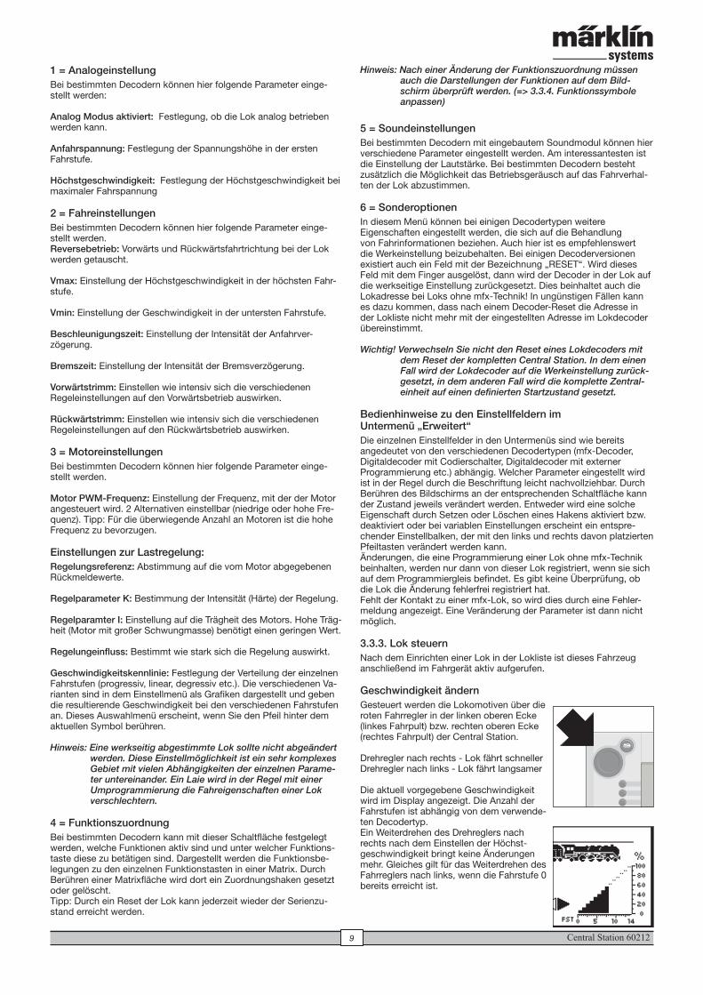
Geschwindigkeit ändernGesteuert werden die Lokomotiven über die roten Fahrregler in der linken oberen Ecke (linkes Fahrpult) bzw. rechten oberen Ecke (rechtes Fahrpult) der Central Station.
Drehregler nach rechts - Lok fährt schnellerDrehregler nach links - Lok fährt langsamer
Die aktuell vorgegebene Geschwindigkeit wird im Display angezeigt. Die Anzahl der Fahrstufen ist abhängig von dem verwende-ten Decodertyp. Ein Weiterdrehen des Drehreglers nach rechts nach dem Einstellen der Höchst-geschwindigkeit bringt keine Änderungen mehr. Gleiches gilt für das Weiterdrehen des Fahrreglers nach links, wenn die Fahrstufe 0 bereits erreicht ist.
1 = AnalogeinstellungBei bestimmten Decodern können hier folgende Parameter einge-stellt werden:
Analog Modus aktiviert: Festlegung, ob die Lok analog betrieben werden kann.
Anfahrspannung: Festlegung der Spannungshöhe in der ersten Fahrstufe.
Höchstgeschwindigkeit: Festlegung der Höchstgeschwindigkeit bei maximaler Fahrspannung
2 = FahreinstellungenBei bestimmten Decodern können hier folgende Parameter einge-stellt werden. Reversebetrieb: Vorwärts und Rückwärtsfahrtrichtung bei der Lok werden getauscht.
Vmax: Einstellung der Höchstgeschwindigkeit in der höchsten Fahr-stufe.
Vmin: Einstellung der Geschwindigkeit in der untersten Fahrstufe.
Beschleunigungszeit: Einstellung der Intensität der Anfahrver- zögerung.
Bremszeit: Einstellung der Intensität der Bremsverzögerung.
Vorwärtstrimm: Einstellen wie intensiv sich die verschiedenen Regeleinstellungen auf den Vorwärtsbetrieb auswirken.
Rückwärtstrimm: Einstellen wie intensiv sich die verschiedenen Regeleinstellungen auf den Rückwärtsbetrieb auswirken.
3 = MotoreinstellungenBei bestimmten Decodern können hier folgende Parameter einge-stellt werden.
Motor PWM-Frequenz: Einstellung der Frequenz, mit der der Motor angesteuert wird. 2 Alternativen einstellbar (niedrige oder hohe Fre-quenz). Tipp: Für die überwiegende Anzahl an Motoren ist die hohe Frequenz zu bevorzugen.
Einstellungen zur Lastregelung:Regelungsreferenz: Abstimmung auf die vom Motor abgegebenen Rückmeldewerte.
Regelparameter K: Bestimmung der Intensität (Härte) der Regelung.
Regelparamter I: Einstellung auf die Trägheit des Motors. Hohe Träg-heit (Motor mit großer Schwungmasse) benötigt einen geringen Wert.
Regelungeinfluss: Bestimmt wie stark sich die Regelung auswirkt.
Geschwindigkeitskennlinie: Festlegung der Verteilung der einzelnen Fahrstufen (progressiv, linear, degressiv etc.). Die verschiedenen Va-rianten sind in dem Einstellmenü als Grafiken dargestellt und geben die resultierende Geschwindigkeit bei den verschiedenen Fahrstufen an. Dieses Auswahlmenü erscheint, wenn Sie den Pfeil hinter dem aktuellen Symbol berühren.
Hinweis: Eine werkseitig abgestimmte Lok sollte nicht abgeändert werden. Diese Einstellmöglichkeit ist ein sehr komplexes Gebiet mit vielen Abhängigkeiten der einzelnen Parame-ter untereinander. Ein Laie wird in der Regel mit einer Umprogrammierung die Fahreigenschaften einer Lok verschlechtern.
4 = FunktionszuordnungBei bestimmten Decodern kann mit dieser Schaltfläche festgelegt werden, welche Funktionen aktiv sind und unter welcher Funktions-taste diese zu betätigen sind. Dargestellt werden die Funktionsbe-legungen zu den einzelnen Funktionstasten in einer Matrix. Durch Berühren einer Matrixfläche wird dort ein Zuordnungshaken gesetzt oder gelöscht. Tipp: Durch ein Reset der Lok kann jederzeit wieder der Serienzu-stand erreicht werden.
Central Station 60212 10
Sobald für eine Lok oder ein Funktionsmodell ein Fahrbefehl (Fahrstufe > 0) oder ein Schaltbefehl existiert, wird sie als „aktiv“ gekennzeichnet. Nach dieser Eigenschaft kann in der Lokliste sortiert werden. Aktive Loks können nicht gelöscht werden.
Auch Mehrfachtraktionen (siehe folgender Abschnitt) werden in der Lokliste angezeigt. Zusätzlich sind diese Einträge mit einem „M“ gekennzeichnet.
MehrfachtraktionZwei oder mehr miteinander gekuppelte Lokomotiven können mit der Central Station auch gemeinsam gesteuert werden. Hierzu wird ein Eintrag in der Lokliste erstellt, der unter einem neuen Namen die darin zusammengefassten Fahrzeuge steuert.
Tipp: Drücken Sie vor den nachfolgenden Schritten die „STOP“-Taste.
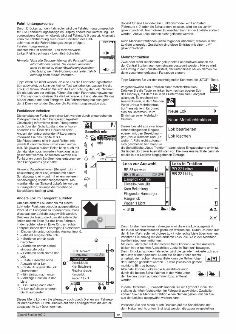
Vorgehensweise zum Erstellen einer Mehrfachtraktion:Drücken Sie die Taste im linken bzw. rechten oberen Eck des Displays, mit dem Sie in das Untermenü zum Fahrgerät gelangen. Es erscheint ein Auswahlmenü, in dem Sie den Punkt „Neue Mehrfachtrak-tion“ auswählen. Es öffnet sich ein Untermenü zum Einrichten einer Mehrfach-traktion.
Dieses besteht aus zwei über-einanderliegenden Eingabe- ebenen mit den Bezeichnun-gen „Neue Traktion“ und „Er-weitert“. Falls nicht automat-sich geschehen berühren Sie die Schaltfläche „Neue Traktion“, damit diese Eingabeebene aktiv ist.Sie finden dort zwei Auswahllisten vor. Die linke Auswahlliste beinhal-tet alle in der Lokliste eingegebenen Einträge.
Durch Drehen am linken Fahrregler wird die erste Lok ausgewählt, die in der Mehrfachtraktion gesteuert werden soll. Durch Drücken auf den linken Fahrregler wird diese Lok in die rechte Liste übernommen. Verfahren Sie analog mit den anderen Loks, die Sie in der Mehrfach-traktion integrieren möchten. Mit dem Fahrregler auf der rechten Seite können Sie den Auswahl-balken in der rechten Auswahlliste „Loks in Traktion“ bewegen. Durch Drücken auf den Fahrregler wird die gerade markierte Lok aus der Liste wieder gelöscht. Durch die beiden Pfeile rechts unterhalb der rechten Auswahlliste kann die Reihenfolge der Einträge geändert werden. Es wird jeweils der gerade markierte Eintrag bewegt.Alternativ können Loks in die Auswahlliste auch durch die beiden Schaltflächen in der Mitte unter den beiden Listen aufgenommen bzw. entfernt werden.
In dem Untermenü „Erweitert“ können Sie ein Symbol für die Dar-stellung der Mehrfachtraktion im Fahrgerät auswählen. Zusätzlich können Sie der Mehrfachtraktion einen Namen geben, mit der Sie aus der Lokliste ausgewählt werden kann.
Verlassen Sie das Menü durch Drücken auf die Schaltfläche mit dem Haken rechts unten. Erst jetzt werden die zuvor eingestellten
FahrtrichtungswechselDurch Drücken auf den Fahrregler wird die Fahrtrichtung umgeschal-tet. Die Fahrtrichtungsanzeige im Display ändert ihre Darstellung. Die vorgegebene Geschwindigkeit wird auf Fahrstufe 0 gesetzt. Alternativ kann die Fahrtrichtung auch durch Berühren des Bild-schirmes an der Fahrtrichtungsanzeige erfolgen.Fahrtrichtungsanzeige:Rechter Pfeil ist schwarz - Lok fährt vorwärtsLinker Pfeil ist schwarz - Lok fährt rückwärts
Hinweis: Nicht alle Decoder können die Fahrtrichtungs-informationen nutzen. Bei diesen Versionen kann es daher zu einer Abweichung zwischen Darstellung der Fahrtrichtung und realer Fahrt-richtung beim Modell kommen.
Tipp: Wenn Sie nicht wissen, ob eine Lok die Fahrtrichtungsinforma-tion auswertet, so kann ein kleiner Test weiterhelfen. Lassen Sie die Lok kurz fahren. Merken Sie sich die Fahrtrichtung der Lok. Nehmen Sie die Lok von der Anlage. Führen Sie einen Fahrtrichtungswechsel im Display durch. Gleisen Sie die Lok wieder auf und steuern Sie das Modell erneut mit dem Fahrgerät. Die Fahrtrichtung hat sich geän-dert? Dann wertet der Decoder die Fahrtrichtungsvorgabe aus.
Funktionen schaltenDie schaltbaren Funktionen einer Lok werden durch entsprechende Piktogramme auf dem Fahrgerät dargestellt. Gleichzeitig informieren diese Piktogramme auch über den Schaltzustand der entspre-chenden Lok. Über das Einrichten oder Ändern der entsprechenden Piktogramme informiert Sie das Kapitel 3.3.4. Die Piktogramme sind in zwei Reihen mit jeweils 8 verschiedenen Positionen aufge-teilt. Die jeweils äußere Reihe kann auch mit den daneben positionierten Funktionstasten geschaltet werden. Ansonsten werden alle Funktionen durch Berühren des entsprechen-den Piktogramms geschaltet.
Hinweis: Dauerfunktionen (Beispiel : Stirn-beleuchtung einer Lok) werden mit einem Schaltvorgang ein- und mit einem weiteren Schaltvorgang wieder ausgeschaltet. Mo-mentfunktionen (Beispiel Lokpfeife) werden nur ausgeführt, solange die zugehörige Schaltfläche betätigt wird.
Andere Lok im Fahrgerät aufrufenUm eine andere Lok oder ein mit einem Lok- oder Funktionsdecoder ausgestattetes Produkt im Fahrgerät zu übernehmen, muss diese aus der Lokliste ausgewählt werden. Drücken Sie hierzu die Auswahltaste in der linken oberen Ecke (für das linke Fahrpult, in der rechten oberen Ecke für das rechte Fahrpult) neben dem Fahrregler. Es erscheint im Display ein entsprechendes Auswahlmenü.1 = Aktuell ausgesuchte Lok 2 = Sortieren primär nach
Favoriten 3 = Sortieren primär aktuell
eingesetzte Loks4 = Sortieren nach Name der
Lok5 = Taste: Beenden ohne
Auswahl einer Lok6 = Taste: Ausgewählte Lok
übernehmen7 = Ein Eintrag nach unten8 = Anzeige Position in der
Liste9 = Ein Eintrag nach oben10 = Lok auf einem anderen
Gerät aufgerufen.
Dieses Menü können Sie alternativ auch durch Drehen am Fahrreg-ler durchsuchen. Durch Drücken auf den Fahrregler wird die aktuell ausgesuchte Lok übernommen.
BR 38 schwarz
BR 216 altrot
Dampflok von Jan
Diesellok von Ulla
Kran Bekohlung
Fliegender Hamburger
Rangierlok
Wagen 1 Licht
ABCA
A
BR 221 altrot
BR 221 bl-bg
Loks zur Auswahl Loks in Traktion
BR 38 schwarz
BR 216 altrot
Dampflok Jan
Diesellok Ulla
Kran Bekohlung
Flieg.Hamburger
Rangierlok
Wagen 1 Licht
� � ��
�
�
�
�
ABCA
�
A
�
Neue Lok
Neue Mehrfachtraktion
Lok bearbeiten
Lok löschen
Central Station 6021211
zu Favoriten etc. In dem Untermenü „Erweitert“ können abhängig vom Decodertyp das Analogverhalten, Höchstgeschwindigkeit, Bremsverzögerung etc. verändert werden. Lesen Sie bitte hierzu die Hinweise im Kapitel 3.3.2.
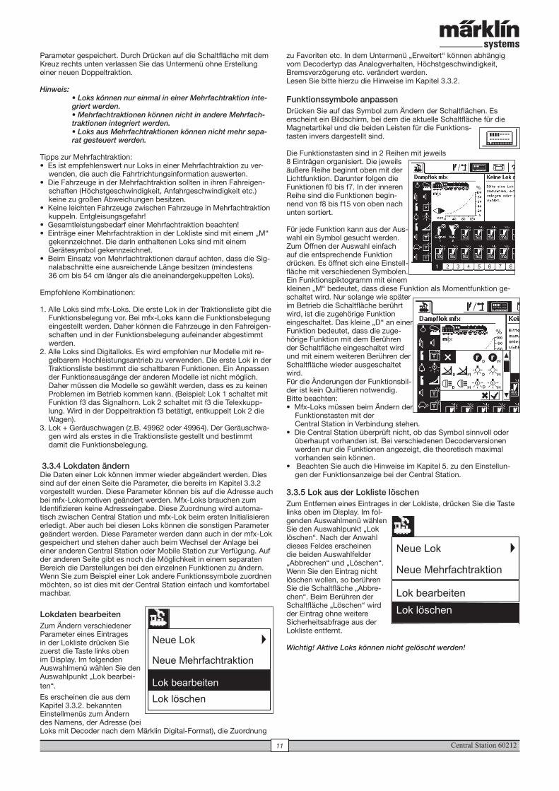
Funktionssymbole anpassenDrücken Sie auf das Symbol zum Ändern der Schaltflächen. Es erscheint ein Bildschirm, bei dem die aktuelle Schaltfläche für die Magnetartikel und die beiden Leisten für die Funktions-tasten invers dargestellt sind.
Die Funktionstasten sind in 2 Reihen mit jeweils 8 Einträgen organisiert. Die jeweils äußere Reihe beginnt oben mit der Lichtfunktion. Darunter folgen die Funktionen f0 bis f7. In der inneren Reihe sind die Funktionen begin-nend von f8 bis f15 von oben nach unten sortiert.
Für jede Funktion kann aus der Aus-wahl ein Symbol gesucht werden. Zum Öffnen der Auswahl einfach auf die entsprechende Funktion drücken. Es öffnet sich eine Einstell-fläche mit verschiedenen Symbolen. Ein Funktionspiktogramm mit einem kleinen „M“ bedeutet, dass diese Funktion als Momentfunktion ge-schaltet wird. Nur solange wie später im Betrieb die Schaltfläche berührt wird, ist die zugehörige Funktion eingeschaltet. Das kleine „D“ an einer Funktion bedeutet, dass die zuge-hörige Funktion mit dem Berühren der Schaltfläche eingeschaltet wird und mit einem weiteren Berühren der Schaltfläche wieder ausgeschaltet wird.Für die Änderungen der Funktionsbil-der ist kein Quittieren notwendig.Bitte beachten:• Mfx-Loks müssen beim Ändern der
Funktionstasten mit der Central Station in Verbindung stehen.
• Die Central Station überprüft nicht, ob das Symbol sinnvoll oder überhaupt vorhanden ist. Bei verschiedenen Decoderversionen werden nur die Funktionen angezeigt, die theoretisch maximal vorhanden sein können.
• Beachten Sie auch die Hinweise im Kapitel 5. zu den Einstellun-gen der Funktionsanzeige bei der Central Station.
3.3.5 Lok aus der Lokliste löschenZum Entfernen eines Eintrages in der Lokliste, drücken Sie die Taste links oben im Display. Im fol-genden Auswahlmenü wählen Sie den Auswahlpunkt „Lok löschen“. Nach der Anwahl dieses Feldes erscheinen die beiden Auswahlfelder „Abbrechen“ und „Löschen“. Wenn Sie den Eintrag nicht löschen wollen, so berühren Sie die Schaltfläche „Abbre-chen“. Beim Berühren der Schaltfläche „Löschen“ wird der Eintrag ohne weitere Sicherheitsabfrage aus der Lokliste entfernt.
Wichtig! Aktive Loks können nicht gelöscht werden!
Parameter gespeichert. Durch Drücken auf die Schaltfläche mit dem Kreuz rechts unten verlassen Sie das Untermenü ohne Erstellung einer neuen Doppeltraktion.
Hinweis: • Loks können nur einmal in einer Mehrfachtraktion inte-griert werden. • Mehrfachtraktionen können nicht in andere Mehrfach-traktionen integriert werden. • Loks aus Mehrfachtraktionen können nicht mehr sepa-rat gesteuert werden.
Tipps zur Mehrfachtraktion:• Es ist empfehlenswert nur Loks in einer Mehrfachtraktion zu ver-
wenden, die auch die Fahrtrichtungsinformation auswerten. • Die Fahrzeuge in der Mehrfachtraktion sollten in ihren Fahreigen-
schaften (Höchstgeschwindigkeit, Anfahrgeschwindigkeit etc.) keine zu großen Abweichungen besitzen.
• Keine leichten Fahrzeuge zwischen Fahrzeuge in Mehrfachtraktion kuppeln. Entgleisungsgefahr!
• Gesamtleistungsbedarf einer Mehrfachtraktion beachten!• Einträge einer Mehrfachtraktion in der Lokliste sind mit einem „M“
gekennzeichnet. Die darin enthaltenen Loks sind mit einem Gerätesymbol gekennzeichnet.
• Beim Einsatz von Mehrfachtraktionen darauf achten, dass die Sig-nalabschnitte eine ausreichende Länge besitzen (mindestens 36 cm bis 54 cm länger als die aneinandergekuppelten Loks).
Empfohlene Kombinationen:
1. Alle Loks sind mfx-Loks. Die erste Lok in der Traktionsliste gibt die Funktionsbelegung vor. Bei mfx-Loks kann die Funktionsbelegung eingestellt werden. Daher können die Fahrzeuge in den Fahreigen-schaften und in der Funktionsbelegung aufeinander abgestimmt werden.
2. Alle Loks sind Digitalloks. Es wird empfohlen nur Modelle mit re-gelbarem Hochleistungsantrieb zu verwenden. Die erste Lok in der Traktionsliste bestimmt die schaltbaren Funktionen. Ein Anpassen der Funktionsausgänge der anderen Modelle ist nicht möglich. Daher müssen die Modelle so gewählt werden, dass es zu keinen Problemen im Betrieb kommen kann. (Beispiel: Lok 1 schaltet mit Funktion f3 das Signalhorn. Lok 2 schaltet mit f3 die Telexkupp-lung. Wird in der Doppeltraktion f3 betätigt, entkuppelt Lok 2 die Wagen).
3. Lok + Geräuschwagen (z.B. 49962 oder 49964). Der Geräuschwa-gen wird als erstes in die Traktionsliste gestellt und bestimmt damit die Funktionsbelegung.
3.3.4 Lokdaten ändernDie Daten einer Lok können immer wieder abgeändert werden. Dies sind auf der einen Seite die Parameter, die bereits im Kapitel 3.3.2 vorgestellt wurden. Diese Parameter können bis auf die Adresse auch bei mfx-Lokomotiven geändert werden. Mfx-Loks brauchen zum Identifizieren keine Adresseingabe. Diese Zuordnung wird automa-tisch zwischen Central Station und mfx-Lok beim ersten Initialisieren erledigt. Aber auch bei diesen Loks können die sonstigen Parameter geändert werden. Diese Parameter werden dann auch in der mfx-Lok gespeichert und stehen daher auch beim Wechsel der Anlage bei einer anderen Central Station oder Mobile Station zur Verfügung. Auf der anderen Seite gibt es noch die Möglichkeit in einem separaten Bereich die Darstellungen bei den einzelnen Funktionen zu ändern. Wenn Sie zum Beispiel einer Lok andere Funktionssymbole zuordnen möchten, so ist dies mit der Central Station einfach und komfortabel machbar.
Lokdaten bearbeitenZum Ändern verschiedener Parameter eines Eintrages in der Lokliste drücken Sie zuerst die Taste links oben im Display. Im folgenden Auswahlmenü wählen Sie den Auswahlpunkt „Lok bearbei-ten“. Es erscheinen die aus dem Kapitel 3.3.2. bekannten Einstellmenüs zum Ändern des Namens, der Adresse (bei Loks mit Decoder nach dem Märklin Digital-Format), die Zuordnung
Neue Lok
Neue Mehrfachtraktion
Lok bearbeiten
Lok löschen
Neue Lok
Neue Mehrfachtraktion
Lok bearbeiten
Lok löschen
Central Station 60212 12
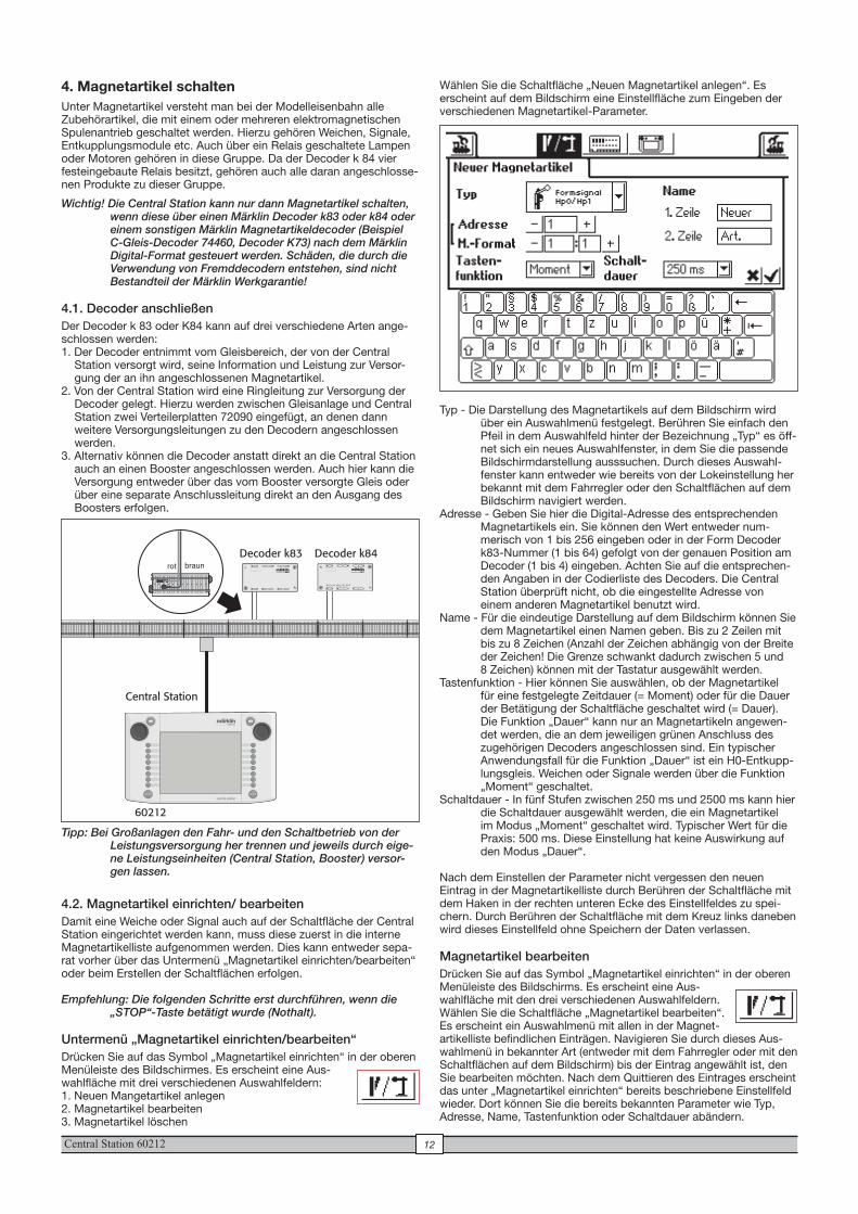
4. Magnetartikel schaltenUnter Magnetartikel versteht man bei der Modelleisenbahn alle Zubehörartikel, die mit einem oder mehreren elektromagnetischen Spulenantrieb geschaltet werden. Hierzu gehören Weichen, Signale, Entkupplungsmodule etc. Auch über ein Relais geschaltete Lampen oder Motoren gehören in diese Gruppe. Da der Decoder k 84 vier festeingebaute Relais besitzt, gehören auch alle daran angeschlosse-nen Produkte zu dieser Gruppe.
Wichtig! Die Central Station kann nur dann Magnetartikel schalten, wenn diese über einen Märklin Decoder k83 oder k84 oder einem sonstigen Märklin Magnetartikeldecoder (Beispiel C-Gleis-Decoder 74460, Decoder K73) nach dem Märklin Digital-Format gesteuert werden. Schäden, die durch die Verwendung von Fremddecodern entstehen, sind nicht Bestandteil der Märklin Werkgarantie!
4.1. Decoder anschließenDer Decoder k 83 oder K84 kann auf drei verschiedene Arten ange-schlossen werden:1. Der Decoder entnimmt vom Gleisbereich, der von der Central
Station versorgt wird, seine Information und Leistung zur Versor-gung der an ihn angeschlossenen Magnetartikel.
2. Von der Central Station wird eine Ringleitung zur Versorgung der Decoder gelegt. Hierzu werden zwischen Gleisanlage und Central Station zwei Verteilerplatten 72090 eingefügt, an denen dann weitere Versorgungsleitungen zu den Decodern angeschlossen werden.
3. Alternativ können die Decoder anstatt direkt an die Central Station auch an einen Booster angeschlossen werden. Auch hier kann die Versorgung entweder über das vom Booster versorgte Gleis oder über eine separate Anschlussleitung direkt an den Ausgang des Boosters erfolgen.
Tipp: Bei Großanlagen den Fahr- und den Schaltbetrieb von der Leistungsversorgung her trennen und jeweils durch eige-ne Leistungseinheiten (Central Station, Booster) versor-gen lassen.
4.2. Magnetartikel einrichten/ bearbeitenDamit eine Weiche oder Signal auch auf der Schaltfläche der Central Station eingerichtet werden kann, muss diese zuerst in die interne Magnetartikelliste aufgenommen werden. Dies kann entweder sepa-rat vorher über das Untermenü „Magnetartikel einrichten/bearbeiten“ oder beim Erstellen der Schaltflächen erfolgen.
Empfehlung: Die folgenden Schritte erst durchführen, wenn die „STOP“-Taste betätigt wurde (Nothalt).
Untermenü „Magnetartikel einrichten/bearbeiten“Drücken Sie auf das Symbol „Magnetartikel einrichten“ in der oberen Menüleiste des Bildschirmes. Es erscheint eine Aus-wahlfläche mit drei verschiedenen Auswahlfeldern:1. Neuen Mangetartikel anlegen2. Magnetartikel bearbeiten3. Magnetartikel löschen
Wählen Sie die Schaltfläche „Neuen Magnetartikel anlegen“. Es erscheint auf dem Bildschirm eine Einstellfläche zum Eingeben der verschiedenen Magnetartikel-Parameter.
Typ - Die Darstellung des Magnetartikels auf dem Bildschirm wird über ein Auswahlmenü festgelegt. Berühren Sie einfach den Pfeil in dem Auswahlfeld hinter der Bezeichnung „Typ“ es öff-net sich ein neues Auswahlfenster, in dem Sie die passende Bildschirmdarstellung ausssuchen. Durch dieses Auswahl-fenster kann entweder wie bereits von der Lokeinstellung her bekannt mit dem Fahrregler oder den Schaltflächen auf dem Bildschirm navigiert werden.
Adresse - Geben Sie hier die Digital-Adresse des entsprechenden Magnetartikels ein. Sie können den Wert entweder num-merisch von 1 bis 256 eingeben oder in der Form Decoder k83-Nummer (1 bis 64) gefolgt von der genauen Position am Decoder (1 bis 4) eingeben. Achten Sie auf die entsprechen-den Angaben in der Codierliste des Decoders. Die Central Station überprüft nicht, ob die eingestellte Adresse von einem anderen Magnetartikel benutzt wird.
Name - Für die eindeutige Darstellung auf dem Bildschirm können Sie dem Magnetartikel einen Namen geben. Bis zu 2 Zeilen mit bis zu 8 Zeichen (Anzahl der Zeichen abhängig von der Breite der Zeichen! Die Grenze schwankt dadurch zwischen 5 und 8 Zeichen) können mit der Tastatur ausgewählt werden.
Tastenfunktion - Hier können Sie auswählen, ob der Magnetartikel für eine festgelegte Zeitdauer (= Moment) oder für die Dauer der Betätigung der Schaltfläche geschaltet wird (= Dauer). Die Funktion „Dauer“ kann nur an Magnetartikeln angewen-det werden, die an dem jeweiligen grünen Anschluss des zugehörigen Decoders angeschlossen sind. Ein typischer Anwendungsfall für die Funktion „Dauer“ ist ein H0-Entkupp-lungsgleis. Weichen oder Signale werden über die Funktion „Moment“ geschaltet.
Schaltdauer - In fünf Stufen zwischen 250 ms und 2500 ms kann hier die Schaltdauer ausgewählt werden, die ein Magnetartikel im Modus „Moment“ geschaltet wird. Typischer Wert für die Praxis: 500 ms. Diese Einstellung hat keine Auswirkung auf den Modus „Dauer“.
Nach dem Einstellen der Parameter nicht vergessen den neuen Eintrag in der Magnetartikelliste durch Berühren der Schaltfläche mit dem Haken in der rechten unteren Ecke des Einstellfeldes zu spei-chern. Durch Berühren der Schaltfläche mit dem Kreuz links daneben wird dieses Einstellfeld ohne Speichern der Daten verlassen.
Magnetartikel bearbeitenDrücken Sie auf das Symbol „Magnetartikel einrichten“ in der oberen Menüleiste des Bildschirms. Es erscheint eine Aus-wahlfläche mit den drei verschiedenen Auswahlfeldern. Wählen Sie die Schaltfläche „Magnetartikel bearbeiten“. Es erscheint ein Auswahlmenü mit allen in der Magnet- artikelliste befindlichen Einträgen. Navigieren Sie durch dieses Aus-wahlmenü in bekannter Art (entweder mit dem Fahrregler oder mit den Schaltflächen auf dem Bildschirm) bis der Eintrag angewählt ist, den Sie bearbeiten möchten. Nach dem Quittieren des Eintrages erscheint das unter „Magnetartikel einrichten“ bereits beschriebene Einstellfeld wieder. Dort können Sie die bereits bekannten Parameter wie Typ, Adresse, Name, Tastenfunktion oder Schaltdauer abändern.
Central Station
60212
d e c o d e r k 8 4
34
21
Decoder k83 Decoder k84rot braun
Central Station 6021213
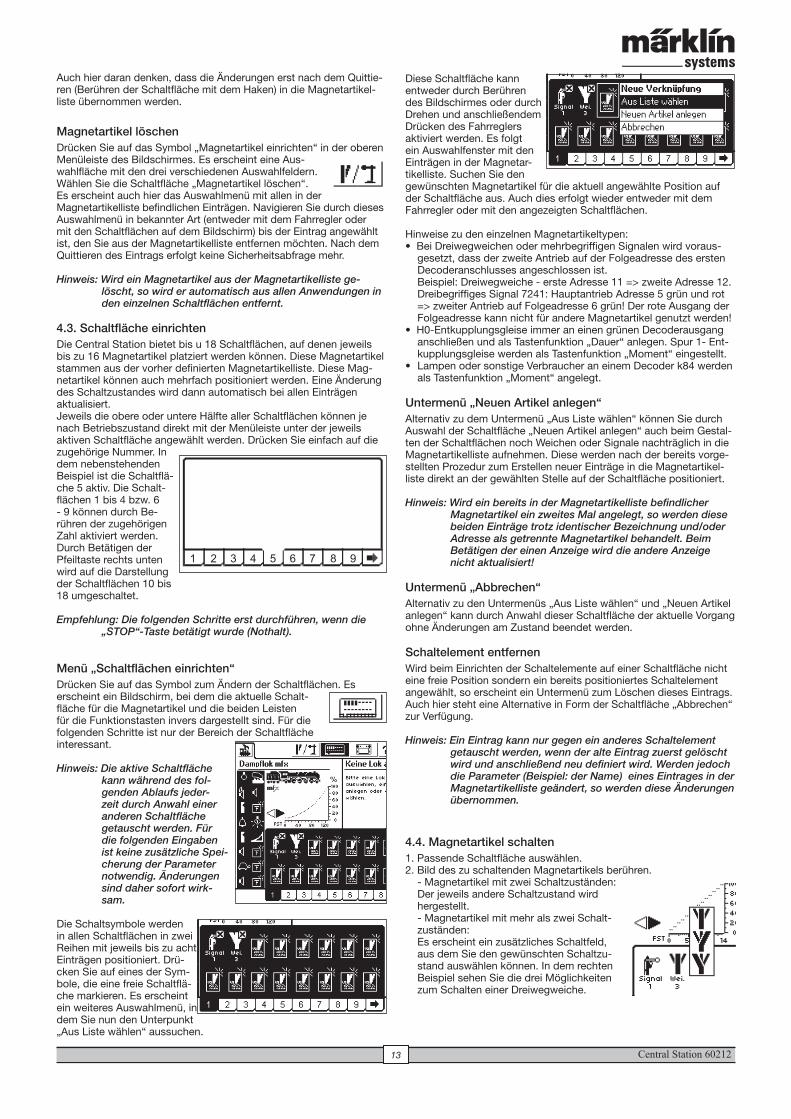
Diese Schaltfläche kann entweder durch Berühren des Bildschirmes oder durch Drehen und anschließendem Drücken des Fahrreglers aktiviert werden. Es folgt ein Auswahlfenster mit den Einträgen in der Magnetar-tikelliste. Suchen Sie den gewünschten Magnetartikel für die aktuell angewählte Position auf der Schaltfläche aus. Auch dies erfolgt wieder entweder mit dem Fahrregler oder mit den angezeigten Schaltflächen.
Hinweise zu den einzelnen Magnetartikeltypen:• Bei Dreiwegweichen oder mehrbegriffigen Signalen wird voraus-
gesetzt, dass der zweite Antrieb auf der Folgeadresse des ersten Decoderanschlusses angeschlossen ist. Beispiel: Dreiwegweiche - erste Adresse 11 => zweite Adresse 12. Dreibegriffiges Signal 7241: Hauptantrieb Adresse 5 grün und rot => zweiter Antrieb auf Folgeadresse 6 grün! Der rote Ausgang der Folgeadresse kann nicht für andere Magnetartikel genutzt werden!
• H0-Entkupplungsgleise immer an einen grünen Decoderausgang anschließen und als Tastenfunktion „Dauer“ anlegen. Spur 1- Ent-kupplungsgleise werden als Tastenfunktion „Moment“ eingestellt.
• Lampen oder sonstige Verbraucher an einem Decoder k84 werden als Tastenfunktion „Moment“ angelegt.
Untermenü „Neuen Artikel anlegen“Alternativ zu dem Untermenü „Aus Liste wählen“ können Sie durch Auswahl der Schaltfläche „Neuen Artikel anlegen“ auch beim Gestal-ten der Schaltflächen noch Weichen oder Signale nachträglich in die Magnetartikelliste aufnehmen. Diese werden nach der bereits vorge-stellten Prozedur zum Erstellen neuer Einträge in die Magnetartikel-liste direkt an der gewählten Stelle auf der Schaltfläche positioniert.
Hinweis: Wird ein bereits in der Magnetartikelliste befindlicher Magnetartikel ein zweites Mal angelegt, so werden diese beiden Einträge trotz identischer Bezeichnung und/oder Adresse als getrennte Magnetartikel behandelt. Beim Betätigen der einen Anzeige wird die andere Anzeige nicht aktualisiert!
Untermenü „Abbrechen“Alternativ zu den Untermenüs „Aus Liste wählen“ und „Neuen Artikel anlegen“ kann durch Anwahl dieser Schaltfläche der aktuelle Vorgang ohne Änderungen am Zustand beendet werden.
Schaltelement entfernen Wird beim Einrichten der Schaltelemente auf einer Schaltfläche nicht eine freie Position sondern ein bereits positioniertes Schaltelement angewählt, so erscheint ein Untermenü zum Löschen dieses Eintrags. Auch hier steht eine Alternative in Form der Schaltfläche „Abbrechen“ zur Verfügung.
Hinweis: Ein Eintrag kann nur gegen ein anderes Schaltelement getauscht werden, wenn der alte Eintrag zuerst gelöscht wird und anschließend neu definiert wird. Werden jedoch die Parameter (Beispiel: der Name) eines Eintrages in der Magnetartikelliste geändert, so werden diese Änderungen übernommen.
4.4. Magnetartikel schalten1. Passende Schaltfläche auswählen.2. Bild des zu schaltenden Magnetartikels berühren.
- Magnetartikel mit zwei Schaltzuständen: Der jeweils andere Schaltzustand wird hergestellt. - Magnetartikel mit mehr als zwei Schalt-zuständen: Es erscheint ein zusätzliches Schaltfeld, aus dem Sie den gewünschten Schaltzu-stand auswählen können. In dem rechten Beispiel sehen Sie die drei Möglichkeiten zum Schalten einer Dreiwegweiche.
Auch hier daran denken, dass die Änderungen erst nach dem Quittie-ren (Berühren der Schaltfläche mit dem Haken) in die Magnetartikel-liste übernommen werden.
Magnetartikel löschenDrücken Sie auf das Symbol „Magnetartikel einrichten“ in der oberen Menüleiste des Bildschirmes. Es erscheint eine Aus-wahlfläche mit den drei verschiedenen Auswahlfeldern. Wählen Sie die Schaltfläche „Magnetartikel löschen“. Es erscheint auch hier das Auswahlmenü mit allen in der Magnetartikelliste befindlichen Einträgen. Navigieren Sie durch dieses Auswahlmenü in bekannter Art (entweder mit dem Fahrregler oder mit den Schaltflächen auf dem Bildschirm) bis der Eintrag angewählt ist, den Sie aus der Magnetartikelliste entfernen möchten. Nach dem Quittieren des Eintrags erfolgt keine Sicherheitsabfrage mehr.
Hinweis: Wird ein Magnetartikel aus der Magnetartikelliste ge-löscht, so wird er automatisch aus allen Anwendungen in den einzelnen Schaltflächen entfernt.
4.3. Schaltfläche einrichtenDie Central Station bietet bis u 18 Schaltflächen, auf denen jeweils bis zu 16 Magnetartikel platziert werden können. Diese Magnetartikel stammen aus der vorher definierten Magnetartikelliste. Diese Mag-netartikel können auch mehrfach positioniert werden. Eine Änderung des Schaltzustandes wird dann automatisch bei allen Einträgen aktualisiert.Jeweils die obere oder untere Hälfte aller Schaltflächen können je nach Betriebszustand direkt mit der Menüleiste unter der jeweils aktiven Schaltfläche angewählt werden. Drücken Sie einfach auf die zugehörige Nummer. In dem nebenstehenden Beispiel ist die Schaltflä-che 5 aktiv. Die Schalt-flächen 1 bis 4 bzw. 6 - 9 können durch Be-rühren der zugehörigen Zahl aktiviert werden. Durch Betätigen der Pfeiltaste rechts unten wird auf die Darstellung der Schaltflächen 10 bis 18 umgeschaltet.
Empfehlung: Die folgenden Schritte erst durchführen, wenn die „STOP“-Taste betätigt wurde (Nothalt).
Menü „Schaltflächen einrichten“Drücken Sie auf das Symbol zum Ändern der Schaltflächen. Es erscheint ein Bildschirm, bei dem die aktuelle Schalt-fläche für die Magnetartikel und die beiden Leisten für die Funktionstasten invers dargestellt sind. Für die folgenden Schritte ist nur der Bereich der Schaltfläche interessant.
Hinweis: Die aktive Schaltfläche kann während des fol-genden Ablaufs jeder-zeit durch Anwahl einer anderen Schaltfläche getauscht werden. Für die folgenden Eingaben ist keine zusätzliche Spei-cherung der Parameter notwendig. Änderungen sind daher sofort wirk-sam.
Die Schaltsymbole werden in allen Schaltflächen in zwei Reihen mit jeweils bis zu acht Einträgen positioniert. Drü-cken Sie auf eines der Sym-bole, die eine freie Schaltflä-che markieren. Es erscheint ein weiteres Auswahlmenü, in dem Sie nun den Unterpunkt „Aus Liste wählen“ aussuchen.
1 2 3 4 5 6 7 8 9
Central Station 60212 14
Hinweis: Befindet sich die Central Station im Nothalt-Zustand, so können die Magnetartikel nicht geschaltet werden. Manuelle Änderungen am Schaltzustand der Magnetarti-kel werden vom System nicht erkannt.
4.5. Signale der 763xx-Serie programmierenZum Programmieren der Digital-Signale der 763xx-Serie (z. B. 76391, 76393 etc.) folgende Schritte durchführen:
1. Signalelektronik in der Verpackung belassen. Die Signalelektronik muss zum Programmieren in den Kontaktbügel in der Verpackung eingerastet sein.
2. Auf der Central Station den passenden Bedienschalter für den jeweiligen Signaltyp in der Magnetartikelliste einrichten. Achten Sie auf die korrekte Adresseinstellung. Bei der Tastenfunktion die Betriebsart „Moment“ wählen. Wichtig: Zum Programmieren die Schaltdauer auf 2500 ms setzen. Bei Signalen mit angebautem Vorsignal nicht vergessen die Schaltelemente für die zugehörigen Hauptsignale einzurichten.
3. Platzieren Sie das neue Schaltelement auf einem der 18 Bedien-ebenen, damit Sie den Magnetartikel schalten können.
4. Schalten Sie die Central Station ab.5. Entfernen Sie den Anschluss der Central Station zur Anlage.
Schließen Sie nur das neu zu programmierende Signal an den Anlagenausgang der Central Station an.
6. Schalten Sie die Central Station ein. Sobald die Central Station betriebsbereit ist, Stop-Taste betätigen (Nothalt)
7. Go-Taste an der Central Station einschalten. Das Signalbild am Signal beginnt zwischen zwei Zuständen hin- und herzuschalten. die nachfolgende Vorgehensweise ist abhängig von dem verwen-deten Signal. 76391/76371/76372: Signal auf dem Bildschirm kurz betätigen. Innerhalb der eingestellten Schaltdauer (2500 ms) wird das Signal sicher programmiert. 76392/76394: Signalzustand Hp1 schalten. Abwarten, bis das Signal wieder beginnt abwechselnd unterschiedliche Signalbilder zu zeigen. Danach den Signalzustand Hp2 schalten. 76395/76397: Die ersten Schritte laufen wie bei den Signalen 76391 bzw. 76393 ab. Danach beginnt das Vorsignal zwischen zwei Signalbildern hin- und herzuschalten. Betätigen Sie jetzt die Funktion Hp1 oder Hp0 von dem zugehörigen Hauptsignal. Wenn das Vorsignal zu einem zweibegriffigen Signal gehört, so drücken Sie ein zweites Mal die Signalfunktion Hp1 oder Hp0, wenn das Vorsignal wieder mit dem abwechselnden Darstellen der verschie-denen Signalbilder begonnen hat. Im anderen Fall betätigen Sie Signalfunktion Hp2 beim zugehörigen Hauptsignal.
8. Das Signal ist jetzt programmiert. Central Station ausschalten. Signal aus der Verpackung nehmen und in die Anlage einbauen.
Wichtig: • Erst wieder die weiteren Schritte beginnen, wenn das Signal zwischen den zwei Signalbildern hin- und her-schaltet. • Es genügt die Schaltbefehle kurz auszulösen. Die not-wendige Schaltdauer ist über den Eintrag von 2500 ms gegeben. Zum späteren Betrieb sollten Sie diese Zeit auf einen praxisgerechteren Wert (z.B. 500 ms) ändern. • Bei zu großen Pausen zwischen den einzelnen Schritten beendet das Signal von sich aus den Programmiervor-gang. Beginnen Sie in diesem Fall durch Drücken der STOP-Taste den ganzen Vorgang von vorne.
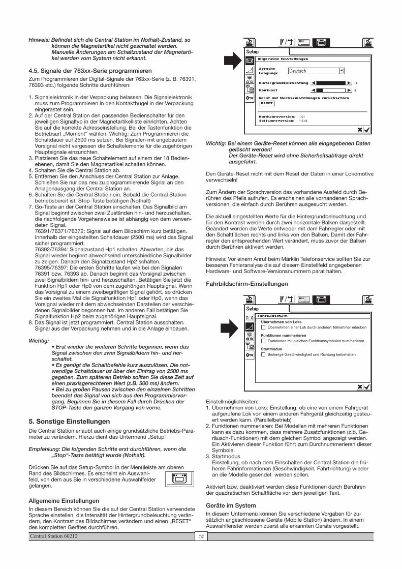
5. Sonstige EinstellungenDie Central Station erlaubt auch einige grundsätzliche Betriebs-Para-meter zu verändern. Hierzu dient das Untermenü „Setup“
Empfehlung: Die folgenden Schritte erst durchführen, wenn die „Stop“-Taste betätigt wurde (Nothalt).
Drücken Sie auf das Setup-Symbol in der Menüleiste am oberen Rand des Bildschirmes. Es erscheint ein Auswahl-feld, von dem aus Sie in verschiedene Auswahlfelder gelangen.
Allgemeine EinstellungenIn diesem Bereich können Sie die auf der Central Station verwendete Sprache einstellen, die Intensität der Hintergrundbeleuchtung verän-dern, den Kontrast des Bildschirmes verändern und einen „RESET“ des kompletten Gerätes durchführen.
Wichtig: Bei einem Geräte-Reset können alle eingegebenen Daten gelöscht werden! Der Geräte-Reset wird ohne Sicherheitsabfrage direkt ausgeführt.
Den Geräte-Reset nicht mit dem Reset der Daten in einer Lokomotive verwechseln!
Zum Ändern der Sprachversion das vorhandene Ausfeld durch Be-rühren des Pfeils aufrufen. Es erscheinen alle vorhandenen Sprach-versionen, die einfach durch Berühren ausgesucht werden.
Die aktuell eingestellten Werte für die Hintergrundbeleuchtung und für den Kontrast werden durch zwei horizontale Balken dargestellt. Geändert werden die Werte entweder mit dem Fahrregler oder mit den Schaltflächen rechts und links von den Balken. Damit der Fahr-regler den entsprechenden Wert verändert, muss zuvor der Balken durch Berühren aktiviert werden.
Hinweis: Vor einem Anruf beim Märklin Telefonservice sollten Sie zur besseren Fehleranalyse die auf diesem Einstellfeld angegebenen Hardware- und Software-Versionsnummern parat halten.
Fahrbildschirm-Einstellungen
Einstellmöglichkeiten:1. Übernehmen von Loks: Einstellung, ob eine von einem Fahrgerät
aufgerufene Lok von einem anderen Fahrgerät gleichzeitig gesteu-ert werden kann. (Parallelbetrieb)
2. Funktionen nummerieren: Bei Modellen mit mehreren Funktionen kann es dazu kommen, dass mehrere Zusatzfunktionen (z.b. Ge-räusch-Funktionen) mit dem gleichen Symbol angezeigt werden. Ein Aktivieren dieser Funktion führt zum Durchnummerieren dieser Symbole.
3. Startmodus Einstellung, ob nach dem Einschalten der Central Station die frü-heren Fahrinformationen (Geschwindigkeit, Fahrtrichtung) wieder an die Modelle gesendet werden sollen.
Aktiviert bzw. deaktiviert werden diese Funktionen durch Berühren der quadratischen Schaltfläche vor dem jeweiligen Text.
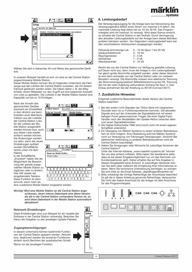
Geräte im SystemIn diesem Untermenü können Sie verschiedene Vorgaben für zu-sätzlich angeschlossene Geräte (Mobile Station) ändern. In einem Auswahlfenster werden zuerst alle erkannten Geräte vorgestellt.
1.011.6.44
Übernehmen von Loks
Funktionen nummerieren
Startmodus
Übernehmen einer Lok durch anderen Teilnehmer erlauben
Funktionen mit gleichen Funktionssymbolen nummerieren
Bisherige Geschwindigkeit und Richtung beibehalten
Central Station 6021215
6. LeistungsbedarfDer Versorgungsausgang für die Anlage kann bei Verwendung des Versorgungstrafos 60052 einen Strom von maximal 3 A liefern. Die maximale Leistung liegt daher bei ca. 45 bis 48 VA. Das Program-miergleis wird mit maximal 1A versorgt. Wird diese Grenze erreicht, so schaltet die Central Station in den Nothalt. Durch Verringerung des aktuellen Leistungsbedarfs auf der Anlage kann dieses Betriebs-problem behoben werden. Von folgendem Leistungsbedarf kann bei den verschiedenen Verbrauchern ausgegangen werden:
Fahrende einmotorige Lok 5 - 10 VA (Spur 1 bis 20 VA)Geräuschelektronik 5 - 10 VARauchgenerator 2 - 5 VAGlühlampe 1 - 2 VAWeichenantrieb 5 - 10 VA
Reicht die von der Central Station zur Verfügung gestellte Leistung auf Dauer nicht aus, dann muss die Anlage in vom Leistungsbedarf her gleich große Abschnitte aufgeteilt werden. Jeder dieser Abschnit-te wird dann entweder von der Central Station oder von weiteren Boostern versorgt. Die Abschnitte müssen eine elektrische Trennung der Stromversorgung besitzen (Mittelleitertrennung bei H0, Trennung der mit der roten Zuleitung verbundenen Schiene bei Spur 1). Den Einbau entnehmen Sie der Anleitung zu 60129 (Connect 6017).
7. Zusätzliche Hinweise:Folgende zusätzliche Besonderheiten dieser Version der Central Station beachten:
1. Bei den ersten Licht-Signalen der 763xx-Serie mit integriertem Decoder kann es zu Funktionsproblemen kommen. Die aktuellen Signale sind auf der Unterseite der Signalelektronik mit einem farbigen Punkt gekennzeichnet. Fragen Sie Ihren Digital-Fach-händler nach den Modalitäten der Update-Aktion zwischen alten und neuen Signalelektroniken.
2. Die Digital-Drehscheibe 7686 wird (noch) nicht mit einem eigenen Schaltfeld unterstützt.
3. Ein Übergang von Märklin Systems zu einem anderen Betriebssys-tem ist nicht möglich. Eine Oberleitung wird bei Märklin Systems nicht zur Versorgung von Fahrzeugen herangezogen. Vorsicht! Bei elektrischer Verbindung zu anderen Betriebssystemen wird die Central Station beschädigt!
4. Haben Sie Anregungen oder Wünsche für zukünftige Versionen der Central Station? Unter der Internet-Adresse „www.maerklin-systems.de“ können Sie uns dies einfach mitteilen. Bitte haben Sie Verständnis dafür, dass es bei dieser Eingabemöglichkeit nur um das Sammeln von Kundenreaktionen geht. Daher erhalten Sie auf Ihre Angaben in diesem Eingabefeld keine Antwort. In zukünftigen Versionen kön-nen Sie dann aber vielleicht die Umsetzung Ihrer Informationen er-leben. Wenn Sie technische Unterstützung benötigen, so wenden Sie sich bitte an die Email-Adresse „[email protected]“
5. Bitte unbedingt die richtige Reihenfolge der Anschlüsse beachten! Es gilt die in dieser Anleitung genannte Reihenfolge. Vertauschen Sie nicht den Kabel-Anschluss für die Anlage mit dem Anschluss für das Programmiergleis.
Wählen Sie dort in bekannter Art und Weise das gewünschte Gerät aus.
In unserem Beispiel handelt es sich um eine an die Central Station angeschlossene Mobile Station. Dieser Mobile Station können Sie im folgenden Untermenü die Fahr-zeuge aus der Lokliste der Central Station zuweisen, die mit diesem Fahrpult gesteuert werden sollen. Sie haben daher z. B. die Mög-lichkeit, einem Mitspieler nur den Zugriff auf eine begrenzte Auswahl von Loks zu gestatten. Die Lokliste in der Mobile Station besitzt eine Kapazität von bis zu 10 Einträgen.
Nach der Anwahl des gewünschten Gerätes erscheint ein Einstellfeld, in dem ähnlich wie beim Erstellen einer Mehrfach-traktion aus der Lokliste der Central Station Loks für die Lokliste der Mo-bile Station ausgewählt werden können bzw. auch aus dieser Liste wieder entfernt werden können. Die Änderungen werden nur aktiv, wenn die neuen Einstellungen quittiert wurden (Schaltfläche rechts unten mit dem Haken).In der Schaltfläche „Erweitert“ haben Sie die Möglichkeit die Bezeich-nung der gerade ausge-wählten Mobile Station zu ergänzen oder zu ändern. Hier hilft wieder die eingeblendete Tastatur. Diese Funktion ist dann sinnvoll, wenn mehr als eine zusätzliche Mobile Station eingesetzt werden.
Wichtig! Wird eine Mobile Station an die Central Station ange-schlossen, deren interne Datenbank eine ältere Version als die in der Central Station vorhandene Version ist, so wird diese Datenbank in der Mobile Station automatisch aktualisiert!
Netzwerk-EinstellungenDiese Einstellungen sind zum Beispiel für ein Update der Software in der Central Station notwendig. Beachten Sie hierzu die Vorgaben zu den jeweiligen Update-Paketen.
ZugangsberechtigungenIn diesem Untermenü können bestimmte Funktio-nen der Central Station gesperrt werden. Aktiviert bzw. deaktiviert werden die einzelnen Funktionen einfach durch Berühren der quadratischen Schalt-
fläche vor der jeweiligen Funktion.
Central Station 60212 16
1. IntroductionThe third generation of Märklin multi-train control systems is now ready with Märklin Systems. The Central Station represents the most important component for this. It is responsible for generating the correct control data, it manages the coordination of the components connected to the system, and also offers an easy to use, manageab-le control surface. Trouble-free operation with this complex system is only guaranteed, when you use tested Märklin System components and nothing else. Any use of other makes of products with Märklin Systems will invalidate the manufacturer’s warranty from Märklin. Damages arising from the use of other makes of products is therefore the responsibility of the operator.
When connecting the Central Station and other components to your layout, follow the techniques and principles contained in these instructions. The use of other circuits may easily lead to damage to the electronic components. It is best if you refrain from “expensive” experiments.
The Central Station is not a toy. Make sure that this unit is used by children only as a controller for model trains.
We hope and trust that you will have much enjoyment in the use of the Central Station on your model railroad layout.
Your Märklin Service Team
2. Basic Information for Using the Central Station
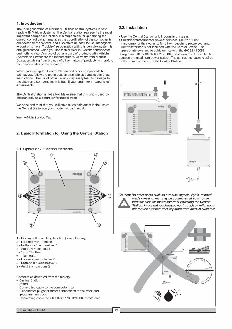
2.1. Operation / Function Elements
1 - Display with switching function (Touch Display)2 - Locomotive Controller 13 - Button for “Locomotive” 14 - Auxiliary Functions 15 - “Stop” Button6 - “Go” Button 7 - Locomotive Controller 28 - Button for “Locomotive” 29 - Auxiliary Functions 2
Contents as delivered from the factory:- Central Station- Stand- Connecting cable to the connector box- 2 connector plugs for direct connections to the track and
programming track- Connecting cable for a 6000/6001/6002/6003 transformer
2.2. Installation
• Use the Central Station only indoors in dry areas.• Suitable transformer for power: Item nos. 60052 / 60055 transformer or their variants for other household power systems. The transformer is not included with the Central Station. The appropriate connecting cable comes with the 60052 / 60055. Using a no. 6000 / 6001/ 6002 or 6003 transformer will mean limita-tions on the maximum power output. The connecting cable required for the above comes with the Central Station.
Caution: No other users such as turnouts, signals, lights, railroad grade crossing, etc. may be connected directly to the terminal clips for the transformer powering the Central Station! Users not receiving power through a digital deco-der require a transformer separate from Märklin Systems!
�
�
�
�
� �
�
�
�
16 V ~
��
!
Central Station 6021217
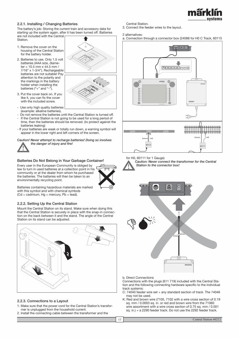
2.2.1. Installing / Changing Batteries The battery’s job: Storing the current train and accessory data for starting up the system again, after it has been turned off. Batteries are not included with the Central Station.
1. Remove the cover on the housing of the Central Station for the battery holder.
2. Batteries to use. Only 1.5 volt batteries (AAA size, diame-ter = 10.5 mm x 44.5 mm / 7/16” x 1-3/4”). Rechargeable batteries are not suitable! Pay attention to the polarity and the markings in the battery holder when installing the batteries (“+” and “-”).
3. Put the cover back on. If you like it, you can fix the cover with the included screw.
- Use only high quality batteries (example: alkaline batteries).
- Do not remove the batteries until the Central Station is turned off.- If the Central Station is not going to be used for a long period of
time, then the batteries should be removed. (to protect against the batteries leaking)
- If your batteries are weak or totally run down, a warning symbol will appear in the lower right and left corners of the screen.
Caution! Never attempt to recharge batteries! Doing so involves the danger of injury and fire!
Batteries Do Not Belong in Your Garbage Container!Every user in the European Community is obliged by law to turn in used batteries at a collection point in his community or at the dealer from whom he purchased the batteries. The batteries will then be taken to an environmentally recycling point.
Batteries containing hazardous materials are marked with this symbol and with chemical symbols (Cd = cadmium, Hg = mercury, Pb = lead).
2.2.2. Setting Up the Central Station Mount the Central Station on its stand. Make sure when doing this that the Central Station is securely in place with the snap-in connec-tion on the back between it and the stand. The angle of the Central Station on its stand can be adjusted.
2.2.3. Connections to a Layout1. Make sure that the power cord for the Central Station’s transfor-
mer is unplugged from the household current.2. Install the connecting cable between the transformer and the
Titel: »Batteriefach öffnen«Seite Nr: 6Datei: 6 Batteriefach öffnen.AIDatei-Typ: Adobe Illustrator 10.0Anleitung: 610 571 »Centralstation«Artikel-Nr.: 60212Datum: 22.11.2004
Central Station.3. Connect the feeder wires to the layout.
2 alternatives: a. Connection through a connector box (24088 for H0 C Track, 60115
for H0, 60111 for 1 Gauge)Caution: Never connect the transformer for the Central Station to the connector box!
b. Direct Connections Connections with the plugs (611 719) included with the Central Sta-tion and the following connecting hardware specific to the individual track systems: C: 74040 feeder wire set + any standard section of track. The 74046 may not be used.K: Red and brown wire (7105, 7102 with a wire cross section of 0.19 sq. mm / 0.0003 sq. in. or red and brown wire from the 71060 wire assortment with a wire cross section of 0.75 sq. mm / 0.001 sq. in.) + a 2290 feeder track. Do not use the 2292 feeder track.
6011560111
redbrownredbrown
!
!
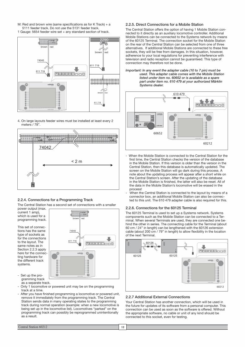
Central Station 60212 18
M: Red and brown wire (same specifications as for K Track) + a 5111 feeder track. Do not use the 5131 feeder track. 1 Gauge: 5654 feeder wire set + any standard section of track.
4. On large layouts feeder wires must be installed at least every 2 meters / 78”.
2.2.4. Connections for a Programming TrackThe Central Station has a second set of connections with a smaller power output (max. current 1 amp), which is used for a programming track.
This set of connec-tions has the same type of sockets as for the connections to the layout. The same notes as in Section 2.2.3 apply here for the connec-ting hardware for the different track systems.
- Set up the pro-gramming track as a separate track.
- Only 1 locomotive or powered unit may be on the programming track at a time.
- After you have finished programming a locomotive or powered unit, remove it immediately from the programming track. The Central Station sends data in many operating states to the programming track during normal operation (example: when a new locomotive is being set up in the locomotive list). Locomotives “parked” on the programming track can possibly be reprogrammed unintentionally as a result.
611 719
74040
redbrown
611 719
redbrown
611 719
redbrown
< 2 m
74042
611 719
74040
redbrown
2.2.5. Direct Connections for a Mobile StationThe Central Station offers the option of having 1 Mobile Station con-nected to it directly as an auxiliary locomotive controller. Additional Mobile Stations can be connected to the Systems network by means of the 60125 Terminal. The connection socket for the Mobile Station on the rear of the Central Station can be selected from one of three alternatives. If additional Mobile Stations are connected to these free sockets, they will be free from damages. In this situation, however, adherence to your local regulations for preventing interference with television and radio reception cannot be guaranteed. This type of connection may therefore not be done.
Important: In any event the adapter cable (10 to 7 pin) must be used. This adapter cable comes with the Mobile Station listed under item no. 60652 or is available as a spare part under item no. 610 479 at your authorized Märklin Systems dealer.
- When the Mobile Station is connected to the Central Station for the first time, the Central Station checks the version of the database in the Mobile Station. If this version is older than the version in the Central Station, then this database is automatically updated. The screen on the Mobile Station will go dark during this process. A note about the updating process will appear after a short while on the Central Station’s screen. After the updating of the database in the Mobile Station is finished, the latter will also be reset. All of the data in the Mobile Station’s locomotive will be erased in the process!
- When the Central Station is connected to the layout by means of a connector box, an additional Mobile Station can also be connec-ted to this unit. The 610 479 adapter cable is also required for this.
2.2.6. Connections for the 60125 Terminal The 60125 Terminal is used to set up a Systems network. Systems components such as the Mobile Station can be connected to a Ter-minal. When several Terminals are used, they are connected one be-hind the other in series. The connecting cable for the Terminal (about 60 cm / 24” in length) can be lengthened with the 60126 extension cable (about 200 cm / 79” in length) to allow flexibility in the location of the next Terminal.
2.2.7 Additional External ConnectionsYour Central Station has another connection, which will be used in the future for updates of its software from a personal computer. This connection can be used as soon as the software is offered. Without the appropriate software, no cable or unit of any kind should be connected to this socket, even for testing.
STOP
610 479
60652
60212
60212
term
inal
term
inal
60126
60125 60125
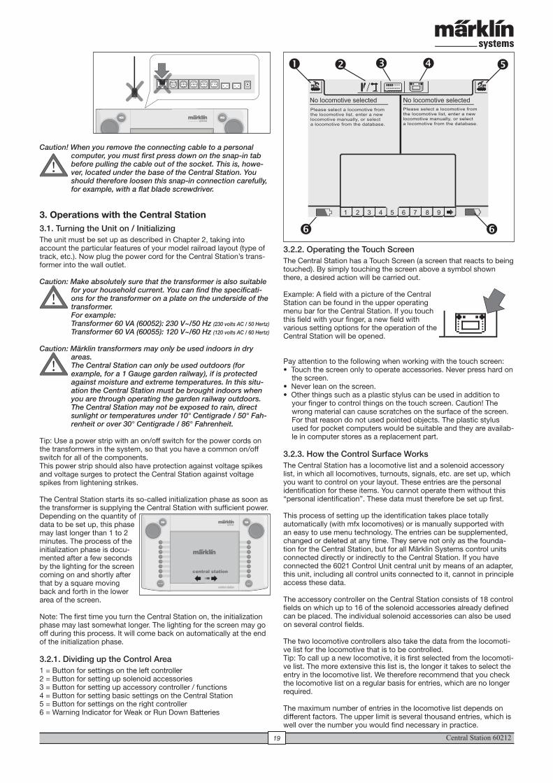
Central Station 6021219
Caution! When you remove the connecting cable to a personal computer, you must first press down on the snap-in tab before pulling the cable out of the socket. This is, howe-ver, located under the base of the Central Station. You should therefore loosen this snap-in connection carefully, for example, with a flat blade screwdriver.
3. Operations with the Central Station3.1. Turning the Unit on / InitializingThe unit must be set up as described in Chapter 2, taking into account the particular features of your model railroad layout (type of track, etc.). Now plug the power cord for the Central Station’s trans-former into the wall outlet.
Caution: Make absolutely sure that the transformer is also suitable for your household current. You can find the specificati-ons for the transformer on a plate on the underside of the transformer. For example: Transformer 60 VA (60052): 230 V~/50 Hz (230 volts AC / 50 Hertz)
Transformer 60 VA (60055): 120 V~/60 Hz (120 volts AC / 60 Hertz)
Caution: Märklin transformers may only be used indoors in dry
areas. The Central Station can only be used outdoors (for example, for a 1 Gauge garden railway), if is protected against moisture and extreme temperatures. In this situ-ation the Central Station must be brought indoors when you are through operating the garden railway outdoors. The Central Station may not be exposed to rain, direct sunlight or temperatures under 10° Centigrade / 50° Fah-renheit or over 30° Centigrade / 86° Fahrenheit.
Tip: Use a power strip with an on/off switch for the power cords on the transformers in the system, so that you have a common on/off switch for all of the components.This power strip should also have protection against voltage spikes and voltage surges to protect the Central Station against voltage spikes from lightening strikes.
The Central Station starts its so-called initialization phase as soon as the transformer is supplying the Central Station with sufficient power. Depending on the quantity of data to be set up, this phase may last longer than 1 to 2 minutes. The process of the initialization phase is docu-mented after a few seconds by the lighting for the screen coming on and shortly after that by a square moving back and forth in the lower area of the screen.
Note: The first time you turn the Central Station on, the initialization phase may last somewhat longer. The lighting for the screen may go off during this process. It will come back on automatically at the end of the initialization phase.
3.2.1. Dividing up the Control Area1 = Button for settings on the left controller2 = Button for setting up solenoid accessories3 = Button for setting up accessory controller / functions4 = Button for setting basic settings on the Central Station5 = Button for settings on the right controller6 = Warning Indicator for Weak or Run Down Batteries
!
central station
1 2 3 4 5 6 7 8 9
No locomotive selected No locomotive selected Please select a locomotive from the locomotive list, enter a new locomotive manually, or select a locomotive from the database.
Please select a locomotive from the locomotive list, enter a new locomotive manually, or select a locomotive from the database.
� � � � �
� �3.2.2. Operating the Touch Screen The Central Station has a Touch Screen (a screen that reacts to being touched). By simply touching the screen above a symbol shown there, a desired action will be carried out. Example: A field with a picture of the Central Station can be found in the upper operating menu bar for the Central Station. If you touch this field with your finger, a new field with various setting options for the operation of the Central Station will be opened.
Pay attention to the following when working with the touch screen:• Touch the screen only to operate accessories. Never press hard on
the screen. • Never lean on the screen.• Other things such as a plastic stylus can be used in addition to
your finger to control things on the touch screen. Caution! The wrong material can cause scratches on the surface of the screen. For that reason do not used pointed objects. The plastic stylus used for pocket computers would be suitable and they are availab-le in computer stores as a replacement part.
3.2.3. How the Control Surface Works The Central Station has a locomotive list and a solenoid accessory list, in which all locomotives, turnouts, signals, etc. are set up, which you want to control on your layout. These entries are the personal identification for these items. You cannot operate them without this “personal identification”. These data must therefore be set up first.
This process of setting up the identification takes place totally automatically (with mfx locomotives) or is manually supported with an easy to use menu technology. The entries can be supplemented, changed or deleted at any time. They serve not only as the founda-tion for the Central Station, but for all Märklin Systems control units connected directly or indirectly to the Central Station. If you have connected the 6021 Control Unit central unit by means of an adapter, this unit, including all control units connected to it, cannot in principle access these data.
The accessory controller on the Central Station consists of 18 control fields on which up to 16 of the solenoid accessories already defined can be placed. The individual solenoid accessories can also be used on several control fields.
The two locomotive controllers also take the data from the locomoti-ve list for the locomotive that is to be controlled.Tip: To call up a new locomotive, it is first selected from the locomoti-ve list. The more extensive this list is, the longer it takes to select the entry in the locomotive list. We therefore recommend that you check the locomotive list on a regular basis for entries, which are no longer required.
The maximum number of entries in the locomotive list depends on different factors. The upper limit is several thousand entries, which is well over the number you would find necessary in practice.
!
60212
!
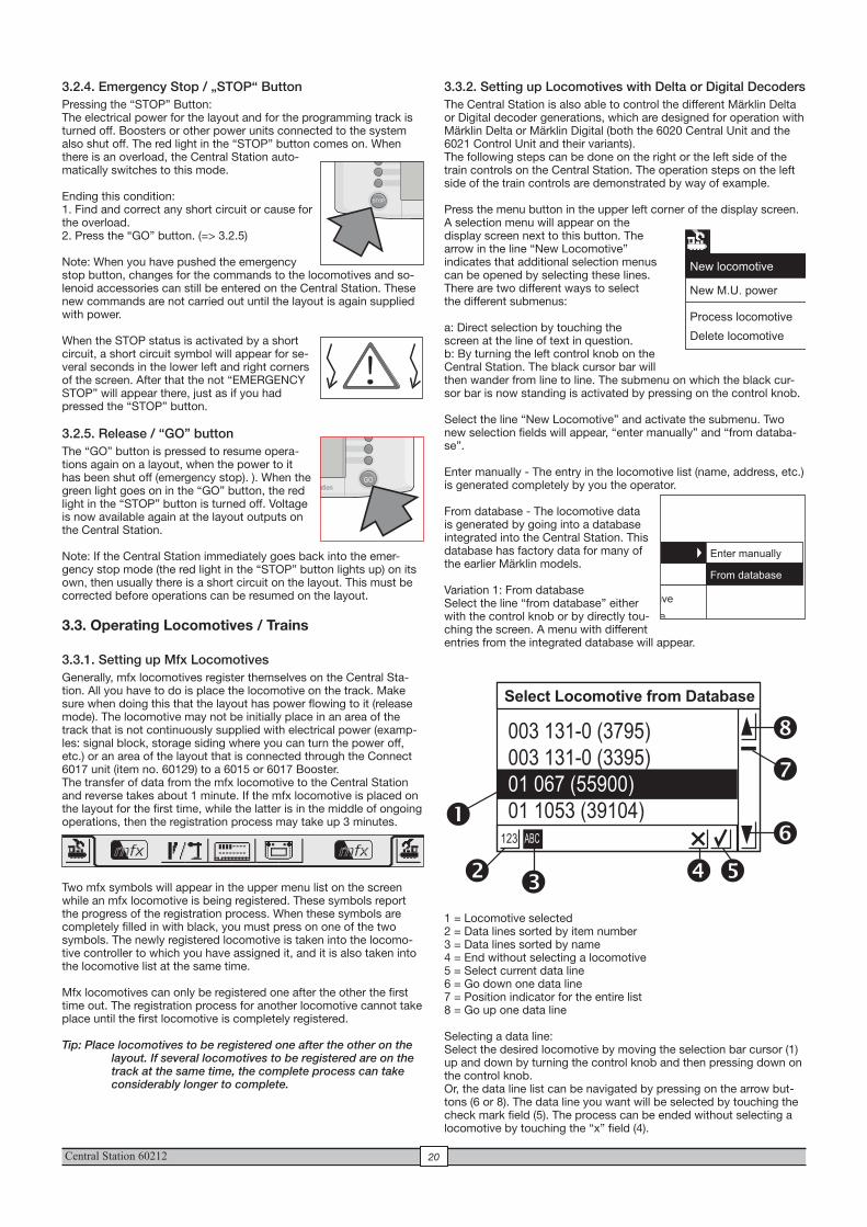
Central Station 60212 20
3.3.2. Setting up Locomotives with Delta or Digital DecodersThe Central Station is also able to control the different Märklin Delta or Digital decoder generations, which are designed for operation with Märklin Delta or Märklin Digital (both the 6020 Central Unit and the 6021 Control Unit and their variants).The following steps can be done on the right or the left side of the train controls on the Central Station. The operation steps on the left side of the train controls are demonstrated by way of example.
Press the menu button in the upper left corner of the display screen. A selection menu will appear on the display screen next to this button. The arrow in the line “New Locomotive” indicates that additional selection menus can be opened by selecting these lines. There are two different ways to select the different submenus:
a: Direct selection by touching the screen at the line of text in question.b: By turning the left control knob on the Central Station. The black cursor bar will then wander from line to line. The submenu on which the black cur-sor bar is now standing is activated by pressing on the control knob.
Select the line “New Locomotive” and activate the submenu. Two new selection fields will appear, “enter manually” and “from databa-se”.
Enter manually - The entry in the locomotive list (name, address, etc.) is generated completely by you the operator.
From database - The locomotive data is generated by going into a database integrated into the Central Station. This database has factory data for many of the earlier Märklin models.
Variation 1: From databaseSelect the line “from database” either with the control knob or by directly tou-ching the screen. A menu with different entries from the integrated database will appear.
1 = Locomotive selected 2 = Data lines sorted by item number3 = Data lines sorted by name4 = End without selecting a locomotive5 = Select current data line6 = Go down one data line7 = Position indicator for the entire list8 = Go up one data line
Selecting a data line:Select the desired locomotive by moving the selection bar cursor (1) up and down by turning the control knob and then pressing down on the control knob.Or, the data line list can be navigated by pressing on the arrow but-tons (6 or 8). The data line you want will be selected by touching the check mark field (5). The process can be ended without selecting a locomotive by touching the “x” field (4).
3.2.4. Emergency Stop / „STOP“ ButtonPressing the “STOP” Button:The electrical power for the layout and for the programming track is turned off. Boosters or other power units connected to the system also shut off. The red light in the “STOP” button comes on. When there is an overload, the Central Station auto-matically switches to this mode.
Ending this condition:1. Find and correct any short circuit or cause for the overload.2. Press the “GO” button. (=> 3.2.5)
Note: When you have pushed the emergency stop button, changes for the commands to the locomotives and so-lenoid accessories can still be entered on the Central Station. These new commands are not carried out until the layout is again supplied with power.
When the STOP status is activated by a short circuit, a short circuit symbol will appear for se-veral seconds in the lower left and right corners of the screen. After that the not “EMERGENCY STOP” will appear there, just as if you had pressed the “STOP” button.
3.2.5. Release / “GO” buttonThe “GO” button is pressed to resume opera-tions again on a layout, when the power to it has been shut off (emergency stop). ). When the green light goes on in the “GO” button, the red light in the “STOP” button is turned off. Voltage is now available again at the layout outputs on the Central Station.
Note: If the Central Station immediately goes back into the emer-gency stop mode (the red light in the “STOP” button lights up) on its own, then usually there is a short circuit on the layout. This must be corrected before operations can be resumed on the layout.
3.3. Operating Locomotives / Trains
3.3.1. Setting up Mfx LocomotivesGenerally, mfx locomotives register themselves on the Central Sta-tion. All you have to do is place the locomotive on the track. Make sure when doing this that the layout has power flowing to it (release mode). The locomotive may not be initially place in an area of the track that is not continuously supplied with electrical power (examp-les: signal block, storage siding where you can turn the power off, etc.) or an area of the layout that is connected through the Connect 6017 unit (item no. 60129) to a 6015 or 6017 Booster.The transfer of data from the mfx locomotive to the Central Station and reverse takes about 1 minute. If the mfx locomotive is placed on the layout for the first time, while the latter is in the middle of ongoing operations, then the registration process may take up 3 minutes.
Two mfx symbols will appear in the upper menu list on the screen while an mfx locomotive is being registered. These symbols report the progress of the registration process. When these symbols are completely filled in with black, you must press on one of the two symbols. The newly registered locomotive is taken into the locomo-tive controller to which you have assigned it, and it is also taken into the locomotive list at the same time.
Mfx locomotives can only be registered one after the other the first time out. The registration process for another locomotive cannot take place until the first locomotive is completely registered.
Tip: Place locomotives to be registered one after the other on the layout. If several locomotives to be registered are on the track at the same time, the complete process can take considerably longer to complete.
GO
Select Locomotive from Database
123 ABC
003 131-0 (3795)
003 131-0 (3395)
01 067 (55900)
01 1053 (39104)
� � ��
�
�
�
�
!
New locomotive
New M.U. power
Process locomotive
Delete locomotive
New locomotive
New M.U. power
Process locomotive
Delete locomotive
Enter manually
From database
mfx mfx
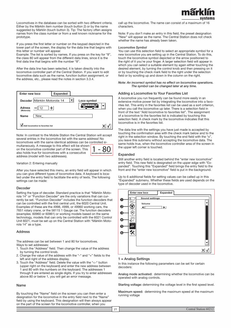
Central Station 6021221
Locomotives in the database can be sorted with two different criteria. Either by the Märklin item number (touch button 2) or by the name suggested by Märklin (touch button 3). Tip: The factory often assigns names from the class number or from a well known nickname for the prototype.
If you press the first letter or number on the keypad depicted in the lower part of the screen, the display for the data line that begins with this letter or number will appear. Example: The list is sorted by names. If you press on the key for “8”, the class 80 will appear from the different data lines, since it is the first data line that begins with the number “8”.
After the data line has been selected, it is taken directly into the locomotive controller part of the Central Station. If you want to edit locomotive data such as the name, function button assignment, or the address, etc., please read the notes in section 3.3.4.
Note: In contrast to the Mobile Station the Central Station will accept several entries in the locomotive list with the same address! No locomotives with the same identical address can be controlled si-multaneously. A message to this effect will be shown on the locomotive controller part of the screen. This also holds true for locomotives with a consecutive address (model with two addresses).
Variation 2: Entering manually
After you have selected this menu, an entry field will appear in which you can give different types of locomotive data. A keyboard is loca-ted under the entry field to facilitate the entry of texts. The following settings can be made:
DecoderSetting the type of decoder. Standard practice is that “Märklin Moto-rola 14” or “Function Decoder” are the only variations that can cur-rently be set. “Function Decoder” includes the function decoders that can be controlled with the first central unit, the 6020 Central Unit. Examples of these are the 4998, 4999, or 49960 working cars, the 7651 rotary crane, or the 58115 1 Gauge car. The function decoders (examples: 60960 or 60961) or working models based on the same technology, models that can only be controlled with the 6021 Control Unit 6021, must be set up on the Central Station with “Märklin Moto-rola 14” as a type. Address
The address can be set between 1 and 80 for locomotives. Ways to set addresses:1. Touch the “Address” field. Then change the value of the address
by turning the control knob.2. Change the value of the address with the “-“ and “+” fields to the
left and right of the address display.3. Touch the “Address” field. Delete the value with the “<-“ button
(upper right on the keyboard) and enter the new address between 1 and 80 with the numbers on the keyboard. The addresses 1 through 9 are entered as single digits. If you try to enter addresses above 80 or below 1, you will get an error message.
Name
By touching the “Name” field on the screen you can then enter a designation for the locomotive in the entry field next to the “Name” field by using the keyboard. This designation will then always appear on the part of the screen for the locomotive controller, when you
call up the locomotive. The name can consist of a maximum of 16 characters.
Note: If you don’t make an entry in this field, the preset designation “New” will appear as the name. The Central Station does not check whether the name has already been taken.
Locomotive SymbolYou can use this selection field to select an appropriate symbol for a new locomotive you are setting up in the Central Station. To do this, touch the locomotive symbol depicted or the arrow positioned to the right of it you’re your finger. A larger selection field will appear in which you can select a suitable element by again either touching the desired element, by turning the control knob and then pressing on it or by touching the check mark field to the right under the selection field or by scrolling up and down in the column on the right.
Note: An incorrect symbol has no effect on locomotive operations. The symbol can be changed later at any time.
Adding a Locomotive to Your Favorites ListA locomotive you run frequently can be found more easily in an extensive motive power list by integrating the locomotive into a favo-rites list. This entry in the favorites list can be used as a sort criterion, when you call the locomotive up later. There is a selection field in front of the text “Add locomotive to favorites list”. The assignment of a locomotive to the favorites list is indicated by touching this selection field. A check mark by the locomotive indicates that this locomotive is in the favorites list.
The data line with the settings you have just made is accepted by touching the confirmation area with the check mark below and to the right in the selection window. By touching the end field with the “x”, you leave this submenu without accepting the locomotive data. The same holds true, when the locomotive controller area of the screen in the upper left corner is touched.
Expanded Still another entry field is located behind the “enter new locomotive” entry field. This new field is designated on the upper edge with “Ex-panded”. Touching this “Expanded” field brings the entry field to the front and the “enter new locomotive” field is put in the background.
Up to 6 additional fields for setting values can be called up in this “Expanded” submenu. Whether these fields are used depends on the type of decoder used in the locomotive.
1 = Analog SettingsIn this instance the following parameters can be set for certain decoders:
Analog mode activated: determining whether the locomotive can be operated with analog controls.
Starting voltage: determining the voltage level in the first speed level.
Maximum speed: determining the maximum speed at the maximum running voltage
Enter new loco Expanded
Decoder Loco symbol
Adress (Motorola)
Name
Add locomotive to favorites list
New_
12
Märklin Motorola 14
1 - 80
Enter new loco Expanded
Sound settings
AC
MAUX
�
�
�
�
�
�
Volume
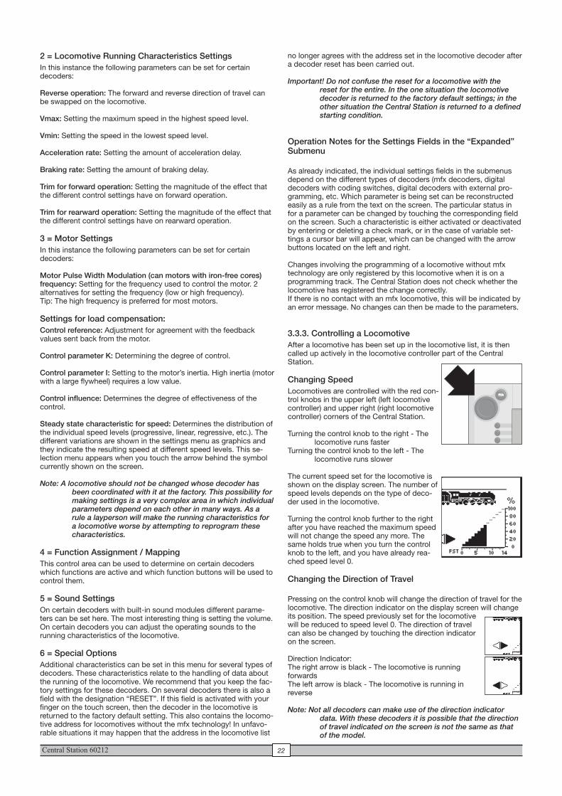
Central Station 60212 22
no longer agrees with the address set in the locomotive decoder after a decoder reset has been carried out.
Important! Do not confuse the reset for a locomotive with the reset for the entire. In the one situation the locomotive decoder is returned to the factory default settings; in the other situation the Central Station is returned to a defined starting condition.
Operation Notes for the Settings Fields in the “Expanded” Submenu
As already indicated, the individual settings fields in the submenus depend on the different types of decoders (mfx decoders, digital decoders with coding switches, digital decoders with external pro-gramming, etc. Which parameter is being set can be reconstructed easily as a rule from the text on the screen. The particular status in for a parameter can be changed by touching the corresponding field on the screen. Such a characteristic is either activated or deactivated by entering or deleting a check mark, or in the case of variable set-tings a cursor bar will appear, which can be changed with the arrow buttons located on the left and right.
Changes involving the programming of a locomotive without mfx technology are only registered by this locomotive when it is on a programming track. The Central Station does not check whether the locomotive has registered the change correctly. If there is no contact with an mfx locomotive, this will be indicated by an error message. No changes can then be made to the parameters.
3.3.3. Controlling a Locomotive After a locomotive has been set up in the locomotive list, it is then called up actively in the locomotive controller part of the Central Station.
Changing Speed Locomotives are controlled with the red con-trol knobs in the upper left (left locomotive controller) and upper right (right locomotive controller) corners of the Central Station.
Turning the control knob to the right - The locomotive runs faster
Turning the control knob to the left - The locomotive runs slower
The current speed set for the locomotive is shown on the display screen. The number of speed levels depends on the type of deco-der used in the locomotive.
Turning the control knob further to the right after you have reached the maximum speed will not change the speed any more. The same holds true when you turn the control knob to the left, and you have already rea-ched speed level 0.
Changing the Direction of Travel
Pressing on the control knob will change the direction of travel for the locomotive. The direction indicator on the display screen will change its position. The speed previously set for the locomotive will be reduced to speed level 0. The direction of travel can also be changed by touching the direction indicator on the screen.
Direction Indicator:The right arrow is black - The locomotive is running forwardsThe left arrow is black - The locomotive is running in reverse
Note: Not all decoders can make use of the direction indicator data. With these decoders it is possible that the direction of travel indicated on the screen is not the same as that of the model.
2 = Locomotive Running Characteristics Settings In this instance the following parameters can be set for certain decoders: Reverse operation: The forward and reverse direction of travel can be swapped on the locomotive.
Vmax: Setting the maximum speed in the highest speed level.
Vmin: Setting the speed in the lowest speed level.
Acceleration rate: Setting the amount of acceleration delay.
Braking rate: Setting the amount of braking delay.
Trim for forward operation: Setting the magnitude of the effect that the different control settings have on forward operation.
Trim for rearward operation: Setting the magnitude of the effect that the different control settings have on rearward operation.
3 = Motor SettingsIn this instance the following parameters can be set for certain decoders:
Motor Pulse Width Modulation (can motors with iron-free cores) frequency: Setting for the frequency used to control the motor. 2 alternatives for setting the frequency (low or high frequency). Tip: The high frequency is preferred for most motors.
Settings for load compensation:Control reference: Adjustment for agreement with the feedback values sent back from the motor.
Control parameter K: Determining the degree of control.
Control parameter I: Setting to the motor’s inertia. High inertia (motor with a large flywheel) requires a low value.
Control influence: Determines the degree of effectiveness of the control.
Steady state characteristic for speed: Determines the distribution of the individual speed levels (progressive, linear, regressive, etc.). The different variations are shown in the settings menu as graphics and they indicate the resulting speed at different speed levels. This se-lection menu appears when you touch the arrow behind the symbol currently shown on the screen.
Note: A locomotive should not be changed whose decoder has been coordinated with it at the factory. This possibility for making settings is a very complex area in which individual parameters depend on each other in many ways. As a rule a layperson will make the running characteristics for a locomotive worse by attempting to reprogram these characteristics.
4 = Function Assignment / MappingThis control area can be used to determine on certain decoders which functions are active and which function buttons will be used to control them.
5 = Sound SettingsOn certain decoders with built-in sound modules different parame-ters can be set here. The most interesting thing is setting the volume. On certain decoders you can adjust the operating sounds to the running characteristics of the locomotive.
6 = Special OptionsAdditional characteristics can be set in this menu for several types of decoders. These characteristics relate to the handling of data about the running of the locomotive. We recommend that you keep the fac-tory settings for these decoders. On several decoders there is also a field with the designation “RESET”. If this field is activated with your finger on the touch screen, then the decoder in the locomotive is returned to the factory default setting. This also contains the locomo-tive address for locomotives without the mfx technology! In unfavo-rable situations it may happen that the address in the locomotive list
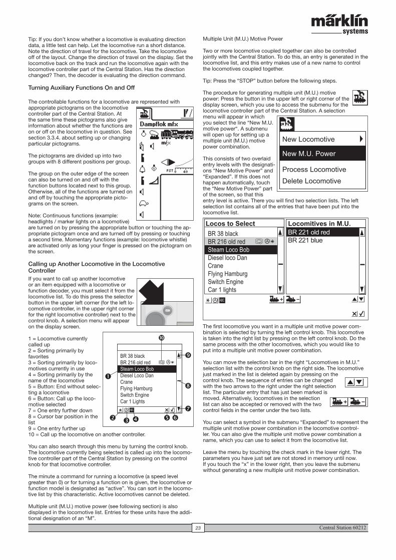
Central Station 6021223
Multiple Unit (M.U.) Motive Power
Two or more locomotive coupled together can also be controlled jointly with the Central Station. To do this, an entry is generated in the locomotive list, and this entry makes use of a new name to control the locomotives coupled together.
Tip: Press the “STOP” button before the following steps.
The procedure for generating multiple unit (M.U.) motive power: Press the button in the upper left or right corner of the display screen, which you use to access the submenu for the locomotive controller part of the Central Station. A selection menu will appear in which you select the line “New M.U. motive power“. A submenu will open up for setting up a multiple unit (M.U.) motive power combination.
This consists of two overlaid entry levels with the designati-ons “New Motive Power” and “Expanded”. If this does not happen automatically, touch the “New Motive Power” part of the screen, so that this entry level is active. There you will find two selection lists. The left selection list contains all of the entries that have been put into the locomotive list.
The first locomotive you want in a multiple unit motive power com-bination is selected by turning the left control knob. This locomotive is taken into the right list by pressing on the left control knob. Do the same process with the other locomotives, which you would like to put into a multiple unit motive power combination.
You can move the selection bar in the right “Locomotives in M.U.” selection list with the control knob on the right side. The locomotive just marked in the list is deleted again by pressing on the control knob. The sequence of entries can be changed with the two arrows to the right under the right selection list. The particular entry that has just been marked is moved. Alternatively, locomotives in the selection list can also be accepted or removed with the two control fields in the center under the two lists.
You can select a symbol in the submenu “Expanded” to represent the multiple unit motive power combination in the locomotive control-ler. You can also give the multiple unit motive power combination a name, which you can use to select it from the locomotive list.
Leave the menu by touching the check mark in the lower right. The parameters you have just set are not stored in memory until now. If you touch the “x” in the lower right, then you leave the submenu without generating a new multiple unit motive power combination.
Tip: If you don’t know whether a locomotive is evaluating direction data, a little test can help. Let the locomotive run a short distance. Note the direction of travel for the locomotive. Take the locomotive off of the layout. Change the direction of travel on the display. Set the locomotive back on the track and run the locomotive again with the locomotive controller part of the Central Station. Has the direction changed? Then, the decoder is evaluating the direction command.
Turning Auxiliary Functions On and Off
The controllable functions for a locomotive are represented with appropriate pictograms on the locomotive controller part of the Central Station. At the same time these pictograms also give information about whether the functions are on or off on the locomotive in question. See section 3.3.4. about setting up or changing particular pictograms.
The pictograms are divided up into two groups with 8 different positions per group.
The group on the outer edge of the screen can also be turned on and off with the function buttons located next to this group. Otherwise, all of the functions are turned on and off by touching the appropriate picto-grams on the screen.
Note: Continuous functions (example: headlights / marker lights on a locomotive) are turned on by pressing the appropriate button or touching the ap-propriate pictogram once and are turned off by pressing or touching a second time. Momentary functions (example: locomotive whistle) are activated only as long your finger is pressed on the pictogram on the screen.
Calling up Another Locomotive in the Locomotive Controller If you want to call up another locomotive or an item equipped with a locomotive or function decoder, you must select it from the locomotive list. To do this press the selector button in the upper left corner (for the left lo-comotive controller, in the upper right corner for the right locomotive controller) next to the control knob. A selection menu will appear on the display screen.
1 = Locomotive currently called up 2 = Sorting primarily by favorites 3 = Sorting primarily by loco-motives currently in use4 = Sorting primarily by the name of the locomotive 5 = Button: End without selec-ting a locomotive6 = Button: Call up the loco-motive selected7 = One entry further down 8 = Cursor bar position in the list9 = One entry further up 10 = Call up the locomotive on another controller.
You can also search through this menu by turning the control knob. The locomotive currently being selected is called up into the locomo-tive controller part of the Central Station by pressing on the control knob for that locomotive controller.
The minute a command for running a locomotive (a speed level greater than 0) or for turning a function on is given, the locomotive or function model is designated as “active”. You can sort in the locomo-tive list by this characteristic. Active locomotives cannot be deleted.
Multiple unit (M.U.) motive power (see following section) is also displayed in the locomotive list. Entries for these units have the addi-tional designation of an “M”.
BR 38 black
BR 216 old red
Steam Loco Bob
Diesel loco Dan
Crane
Flying Hamburg
Switch Engine
Car 1 lights
ABCA
A
BR 221 old red
BR 221 blue
Locos to Select Locomitives in M.U.
BR 38 black
BR 216 old red
Steam Loco Bob
Diesel Loco Dan
Crane
Flying Hamburg
Switch Engine
Car 1 Lights
� � ��
�
�
�
�
ABCA
�
A
�
New Locomotive
New M.U. Power
Process Locomotive
Delete Locomotive
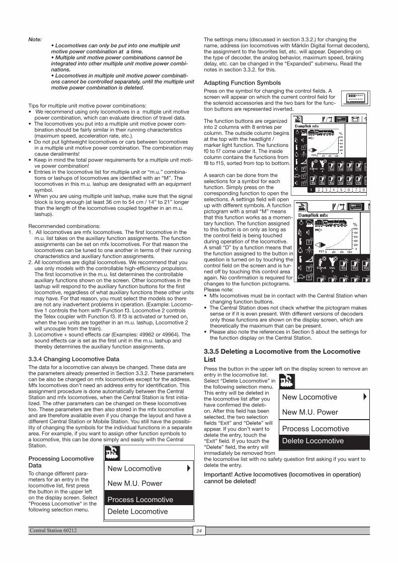
Central Station 60212 24
The settings menu (discussed in section 3.3.2.) for changing the name, address (on locomotives with Märklin Digital format decoders), the assignment to the favorites list, etc. will appear. Depending on the type of decoder, the analog behavior, maximum speed, braking delay, etc. can be changed in the “Expanded” submenu. Read the notes in section 3.3.2. for this.
Adapting Function SymbolsPress on the symbol for changing the control fields. A screen will appear on which the current control field for the solenoid accessories and the two bars for the func-tion buttons are represented inverted.
The function buttons are organized into 2 columns with 8 entries per column. The outside column begins at the top with the headlight / marker light function. The functions f0 to f7 come under it. The inside column contains the functions from f8 to f15, sorted from top to bottom.
A search can be done from the selections for a symbol for each function. Simply press on the corresponding function to open the selections. A settings field will open up with different symbols. A function pictogram with a small “M” means that this function works as a momen-tary function. The function assigned to this button is on only as long as the control field is being touched during operation of the locomotive. A small “D” by a function means that the function assigned to the button in question is turned on by touching the control field on the screen and is tur-ned off by touching this control area again. No confirmation is required for changes to the function pictograms.Please note:• Mfx locomotives must be in contact with the Central Station when
changing function buttons.• The Central Station does not check whether the pictogram makes
sense or if it is even present. With different versions of decoders only those functions are shown on the display screen, which are theoretically the maximum that can be present.
• Please also note the references in Section 5 about the settings for the function display on the Central Station.
3.3.5 Deleting a Locomotive from the Locomotive ListPress the button in the upper left on the display screen to remove an entry in the locomotive list. Select “Delete Locomotive” in the following selection menu. This entry will be deleted in the locomotive list after you have confirmed the deleti-on. After this field has been selected, the two selection fields “Exit” and “Delete” will appear. If you don’t want to delete the entry, touch the “Exit” field. If you touch the “Delete” field, the entry will immediately be removed from the locomotive list with no safety question first asking if you want to delete the entry.
Important! Active locomotives (locomotives in operation) cannot be deleted!
Note: • Locomotives can only be put into one multiple unit motive power combination at a time. • Multiple unit motive power combinations cannot be integrated into other multiple unit motive power combi-nations. • Locomotives in multiple unit motive power combinati-ons cannot be controlled separately, until the multiple unit motive power combination is deleted.
Tips for multiple unit motive power combinations:• We recommend using only locomotives in a multiple unit motive
power combination, which can evaluate direction of travel data. • The locomotives you put into a multiple unit motive power com-
bination should be fairly similar in their running characteristics (maximum speed, acceleration rate, etc.).
• Do not put lightweight locomotives or cars between locomotives in a multiple unit motive power combination. The combination may cause derailments!
• Keep in mind the total power requirements for a multiple unit moti-ve power combination!
• Entries in the locomotive list for multiple unit or “m.u.” combina-tions or lashups of locomotives are identified with an “M”. The locomotives in this m.u. lashup are designated with an equipment symbol.
• When you are using multiple unit lashup, make sure that the signal block is long enough (at least 36 cm to 54 cm / 14” to 21” longer than the length of the locomotives coupled together in an m.u. lashup).
Recommended combinations:1. All locomotives are mfx locomotives. The first locomotive in the
m.u. list takes on the auxiliary function assignments. The function assignments can be set on mfx locomotives. For that reason the locomotives can be tuned to one another in terms of their running characteristics and auxiliary function assignments.
2. All locomotives are digital locomotives. We recommend that you use only models with the controllable high-efficiency propulsion. The first locomotive in the m.u. list determines the controllable auxiliary functions shown on the screen. Other locomotives in the lashup will respond to the auxiliary function buttons for the first locomotive, regardless of what auxiliary functions these other units may have. For that reason, you must select the models so there are not any inadvertent problems in operation. (Example: Locomo-tive 1 controls the horn with Function f3. Locomotive 2 controls the Telex coupler with Function f3. If f3 is activated or turned on, when the two units are together in an m.u. lashup, Locomotive 2 will uncouple from the train).
3. Locomotive + sound effects car (Examples: 49962 or 49964). The sound effects car is set as the first unit in the m.u. lashup and thereby determines the auxiliary function assignments.
3.3.4 Changing Locomotive DataThe data for a locomotive can always be changed. These data are the parameters already presented in Section 3.3.2. These parameters can be also be changed on mfx locomotives except for the address. Mfx locomotives don’t need an address entry for identification. This assignment procedure is done automatically between the Central Station and mfx locomotives, when the Central Station is first initia-lized. The other parameters can be changed on these locomotives too. These parameters are then also stored in the mfx locomotive and are therefore available even if you change the layout and have a different Central Station or Mobile Station. You still have the possibi-lity of changing the symbols for the individual functions in a separate area. For example, if you want to assign other function symbols to a locomotive, this can be done simply and easily with the Central Station.
Processing Locomotive DataTo change different para-meters for an entry in the locomotive list, first press the button in the upper left on the display screen. Select ”Process Locomotive“ in the following selection menu.
New Locomotive
New M.U. Power
Process Locomotive
Delete Locomotive
New Locomotive
New M.U. Power
Process Locomotive
Delete Locomotive
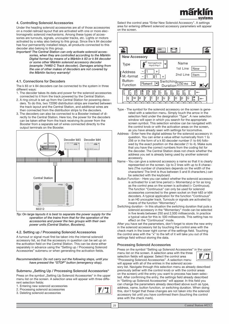
Central Station 6021225
4. Controlling Solenoid AccessoriesUnder the heading solenoid accessories are all of those accessories on a model railroad layout that are activated with one or more elec-tromagnetic solenoid mechanisms. Among these types of acces-sories are turnouts, signals, uncoupler tracks, etc. Lights or motors activated by a relay also belong to this group. Since the k 84 decoder has four permanently installed relays, all products connected to this decoder also belong to this group.Important! The Central Station can only activate solenoid acces-
sories, when they are controlled according to the Märklin Digital format by means of a Märklin k 83 or k 84 decoder or some other Märklin solenoid accessory decoder (example: 74460 C Track decoder). Damages arising from the use of other makes of decoders are not covered by the Märklin factory warranty!
4.1. Connections for Decoders The k 83 or k 84 decoders can be connected to the system in three different ways:1. The decoder takes its data and power for the solenoid accessories
connected to it from the track powered by the Central Station.2. A ring circuit is set up from the Central Station for powering deco-
ders. To do this, two 72090 distribution strips are inserted between the track layout and the Central Station, and additional wires are then connected from the distribution strips to the decoders.
3. The decoders can also be connected to a Booster instead of di-rectly to the Central Station. Here too, the power for the decoders can be taken either from the track receiving its power from the Booster from a separate set of wires connected directly to the output terminals on the Booster.
Tip: On large layouts it is best to separate the power supply for the operation of the trains from that for the operation of the accessories and power the two groups with their own power units (Central Station, Boosters).
4.2. Setting up / Processing Solenoid AccessoriesA turnout or signal must first be taken into the internal solenoid accessory list, so that the accessory in question can be set up on the activation field on the Central Station. This can be done either separately in advance using the “Setting up / Processing Solenoid Accessories” submenu or when generating the activation fields.
Recommendation: Do not carry out the following steps, until you have pressed the “STOP” button (emergency stop).
Submenu „Setting Up / Processing Solenoid Accessories“Press on the symbol „Setting Up Solenoid Accessories“ in the upper menu list on the screen. A selection area will appear with three diffe-rent selection fields: 1. Entering new solenoid accessories2. Processing solenoid accessories 3. Deleting solenoid accessories
Select the control area “Enter New Solenoid Accessory”. A settings area for entering different solenoid accessory parameters will appear on the screen.
Type - The symbol for the solenoid accessory on the screen is gene-rated with a selection menu. Simply touch the arrow in the selection field under the designation “Type”. A new selection window will open in which you search for the appropriate screen symbol. This selection window can be navigated with the control knob or with the activation areas on the screen, as you have already seen with settings for locomotive.
Address - Enter here the digital address for the solenoid accessory in question. You can enter a value either numerically from 1 to 256 or in the form of a k 83 decoder number (1 to 64) follo-wed by the exact position on the decoder (1 to 4). Make sure that you have the correct numbers from the coding list for the decoder. The Central Station does not check whether the address you set is already being used by another solenoid accessory.
Name - You can give a solenoid accessory a name so that it is clearly represented on the screen. Up to 2 lines with up to 8 charac-ters (The number of characters depends on the width of the characters! The limit is thus between 5 and 8 characters.) can be selected with the keyboard.
Button Function - Here you can select whether the solenoid accessory is activated for a set time period (= Momentary) or for as long as the control area on the screen is activated (= Continuous).The function “Continuous” can only be used for solenoid accessories connected to the green socket on their k83 or k84 decoders. A typical application for the function “Continuous” is an H0 uncoupler track. Turnouts or signals are activated by means of the function “Momentary”.
Switching duration - In this situation the switching duration that puts a solenoid accessory in the “Momentary” mode can be selected in five levels between 250 and 2,500 milliseconds. In practice a typical value for this is: 500 milliseconds. This setting has no effect on the “Continuous” mode.
After you have set the parameters, don’t forget to store the new entry in the solenoid accessory list by touching the control area with the check mark in the lower right corner of the settings field. Touching the control area with the “x” to the left of it will take you out of this settings field without storing the data.
Processing Solenoid AccessoriesPress on the symbol “Setting up Solenoid Accessories” in the upper menu list on the screen. A selection area with the three selection fields will appear. Select the control area “Processing Solenoid Accessories”. A selection menu will appear with all of the entries in the solenoid acces-sory list. Navigate through this selection menu as already described previously (either with the control knob or with the control areas on the screen) until the entry you want to process has been selec-ted. After confirming the entry, the settings field already described in “Setting up Solenoid Accessories” will appear. In this field you can change the parameters already described above such as type, address, name, button function, or switching duration. When doing this, don’t forget that these changes are not taken into the solenoid accessory list until you have confirmed them (touching the control area with the check mark).
Central Station
60212
d e c o d e r k 8 4
34
21
Decoder k83 Decoder k84red brown
New Accessory
Type
AddressM.-formatButton- Function
SemaphoreHp0/Hp1
Switching Duration
Name1st Line
2nd Line
New
Item
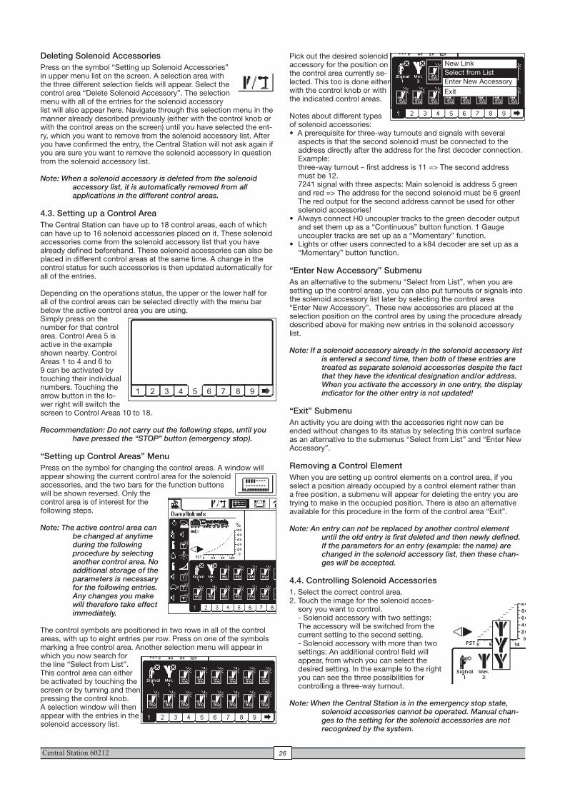
Central Station 60212 26
Pick out the desired solenoid accessory for the position on the control area currently se-lected. This too is done either with the control knob or with the indicated control areas.
Notes about different types of solenoid accessories:• A prerequisite for three-way turnouts and signals with several
aspects is that the second solenoid must be connected to the address directly after the address for the first decoder connection.Example: three-way turnout – first address is 11 => The second address must be 12. 7241 signal with three aspects: Main solenoid is address 5 green and red => The address for the second solenoid must be 6 green! The red output for the second address cannot be used for other solenoid accessories!
• Always connect H0 uncoupler tracks to the green decoder output and set them up as a “Continuous” button function. 1 Gauge uncoupler tracks are set up as a “Momentary” function.
• Lights or other users connected to a k84 decoder are set up as a “Momentary” button function.
“Enter New Accessory” SubmenuAs an alternative to the submenu “Select from List”, when you are setting up the control areas, you can also put turnouts or signals into the solenoid accessory list later by selecting the control area “Enter New Accessory”. These new accessories are placed at the selection position on the control area by using the procedure already described above for making new entries in the solenoid accessory list.
Note: If a solenoid accessory already in the solenoid accessory list is entered a second time, then both of these entries are treated as separate solenoid accessories despite the fact that they have the identical designation and/or address. When you activate the accessory in one entry, the display indicator for the other entry is not updated!
“Exit” SubmenuAn activity you are doing with the accessories right now can be ended without changes to its status by selecting this control surface as an alternative to the submenus “Select from List” and “Enter New Accessory”.
Removing a Control Element When you are setting up control elements on a control area, if you select a position already occupied by a control element rather than a free position, a submenu will appear for deleting the entry you are trying to make in the occupied position. There is also an alternative available for this procedure in the form of the control area “Exit”.
Note: An entry can not be replaced by another control element until the old entry is first deleted and then newly defined. If the parameters for an entry (example: the name) are changed in the solenoid accessory list, then these chan-ges will be accepted.
4.4. Controlling Solenoid Accessories1. Select the correct control area.2. Touch the image for the solenoid acces-
sory you want to control. - Solenoid accessory with two settings: The accessory will be switched from the current setting to the second setting. - Solenoid accessory with more than two settings: An additional control field will appear, from which you can select the desired setting. In the example to the right you can see the three possibilities for controlling a three-way turnout.
Note: When the Central Station is in the emergency stop state, solenoid accessories cannot be operated. Manual chan-ges to the setting for the solenoid accessories are not recognized by the system.
Deleting Solenoid AccessoriesPress on the symbol “Setting up Solenoid Accessories” in upper menu list on the screen. A selection area with the three different selection fields will appear. Select the control area “Delete Solenoid Accessory”. The selection menu with all of the entries for the solenoid accessory list will also appear here. Navigate through this selection menu in the manner already described previously (either with the control knob or with the control areas on the screen) until you have selected the ent-ry, which you want to remove from the solenoid accessory list. After you have confirmed the entry, the Central Station will not ask again if you are sure you want to remove the solenoid accessory in question from the solenoid accessory list.
Note: When a solenoid accessory is deleted from the solenoid accessory list, it is automatically removed from all applications in the different control areas.
4.3. Setting up a Control AreaThe Central Station can have up to 18 control areas, each of which can have up to 16 solenoid accessories placed on it. These solenoid accessories come from the solenoid accessory list that you have already defined beforehand. These solenoid accessories can also be placed in different control areas at the same time. A change in the control status for such accessories is then updated automatically for all of the entries.
Depending on the operations status, the upper or the lower half for all of the control areas can be selected directly with the menu bar below the active control area you are using. Simply press on the number for that control area. Control Area 5 is active in the example shown nearby. Control Areas 1 to 4 and 6 to 9 can be activated by touching their individual numbers. Touching the arrow button in the lo-wer right will switch the screen to Control Areas 10 to 18.
Recommendation: Do not carry out the following steps, until you have pressed the “STOP” button (emergency stop).
“Setting up Control Areas” Menu Press on the symbol for changing the control areas. A window will appear showing the current control area for the solenoid accessories, and the two bars for the function buttons will be shown reversed. Only the control area is of interest for the following steps.
Note: The active control area can be changed at anytime during the following procedure by selecting another control area. No additional storage of the parameters is necessary for the following entries. Any changes you make will therefore take effect immediately.
The control symbols are positioned in two rows in all of the control areas, with up to eight entries per row. Press on one of the symbols marking a free control area. Another selection menu will appear in which you now search for the line “Select from List”. This control area can either be activated by touching the screen or by turning and then pressing the control knob. A selection window will then appear with the entries in the solenoid accessory list.
1 2 3 4 5 6 7 8 9
ExitEnter New AccessorySelect from ListNew Link
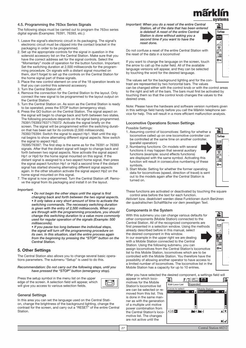
Central Station 6021227
4.5. Programming the 763xx Series Signals The following steps must be carried out to program the 763xx series digital signals (Examples: 76391, 76393, etc.):
1. Leave the signal’s electronic circuit in its packaging. The signal’s electronic circuit must be clipped into the contact bracket in the packaging in order to be programmed.
2. Set up the appropriate controls for the signal in question in the solenoid accessory list on the Central Station. Make sure that you have the correct address set for the signal controls. Select the “Momentary” mode of operation for the button function. Important: Set the switching duration at 2,500 milliseconds for the program-ming procedure. On signals with a distant signal mounted on them, don’t forget to set up the controls on the Central Station for the home signal part of these signals.
3. Place the new control element on one of the 18 operation levels so that you can control this solenoid accessory.
3. Turn the Central Station off.4. Remove the connection for the Central Station to the layout. Only
connect the new signal to be programmed to the layout output on the Central Station.
5. Turn the Central Station on. As soon as the Central Station is ready to be operated, press the STOP button (emergency stop).
6. Press the GO button on the Central Station. The signal aspect on the signal will begin to change back and forth between two states. The following procedure depends on the signal being programmed. 76391/76393/76371/76372: Activate the signal briefly on the screen. The signal will be programmed within the switching durati-on that has been set for its controls (2,500 milliseconds). 76392/76394: Switch the signal to aspect Hp1. Wait until the sig-nal begins to show alternating different signal aspects. Now switch the signal to aspect Hp2. 76395/76397: The first step is the same as for the 76391 or 76393 signals. After that the distant signal will begin to change back and forth between two signal aspects. Now activate the signal aspect Hp1 or Hp0 for the home signal mounted on this signal. If the distant signal is assigned to a two-aspect home signal, then press the signal aspect function Hp1 or Hp0 a second time if the distant signal has started showing alternating different signal aspects again. In the other situation activate the signal aspect Hp2 on the home signal mounted on this signal.
7. The signal is now programmed. Turn the Central Station off. Remo-ve the signal from its packaging and install it on the layout.
Important: • Do not begin the other steps until the signal is first changing back and forth between the two signal aspects. • It only takes a very short amount of time to activate the switching commands. The necessary switching duration is given with the entry of 2,500 milliseconds. When you are through with the programming procedure, you should change this switching duration to a value more commonly used for regular operation of the signals (Example: 500 milliseconds). • If you pause too long between the individual steps, the signal will turn off the programming procedure on its own. In this situation, start the entire process again from the beginning by pressing the “STOP” button on the Central Station.
5. Other SettingsThe Central Station also allows you to change several basic opera-tions parameters. The submenu “Setup” is used to do this.
Recommendation: Do not carry out the following steps, until you have pressed the “STOP” button (emergency stop).
Press the setup symbol in the menu list on the upper edge of the screen. A selection field will appear, which will give you access to various selection fields.
General Settings In this area you can set the language used on the Central Stati-on, change the brightness of the background lighting, change the contrast for the screen, and carry out a “RESET” of the entire Central Station.
Important: When you do a reset of the entire Central Station, all of the data that has been entered is deleted! A reset of the entire Central Station is done without asking you a second time if you want to have the reset done.
Do not confuse a reset of the entire Central Station with the reset of the data in a locomotive!
If you want to change the language on the screen, touch the arrow to call up the outer field. All of the available language versions will appear, and they can be selected by touching the word for the desired language.
The values set for the background lighting and for the con-trast are represented by two horizontal bars. The values can be changed either with the control knob or with the control areas to the right and left of the bars. The bars must first be activated by touching them so that the control knob changes the values to the desired ones.
Note: Please have the hardware and software version numbers given in this settings field handy before you call the Märklin telephone ser-vice for help. This will result in a more efficient malfunction analysis.
Locomotive Operations Screen Settings Possible Settings:1. Assuming control of locomotives: Setting for whether a
locomotive called up on one locomotive controller can be controlled at the same time on another controller. (parallel operation)
2. Numbering functions: On models with several functions it may happen that several auxiliary functions (example: sound effects functions) are displayed with the same symbol. Activating this function will result in consecutive numbering of these symbols.
3. Start Mode: Setting for whether the former operating data for locomotives (speed, direction of travel) is sent out to the models again after the Central Station is turned on.
These functions are activated or deactivated by touching the square control area before the text for each function.
Aktiviert bzw. deaktiviert werden diese Funktionen durch Berühren der quadratischen Schaltfläche vor dem jeweiligen Text.
Components in the SystemWith this submenu you can change various defaults for other components (Mobile Station) connected to the Central Station. All of the recognized components are first presented in a selection window. Using the methods already described before in this manual, select the desired component in this window. In our example in the upper right we are dealing with a Mobile Station connected to the Central Station. Using the following submenu, you can assign locomotives from the Central Station’s locomotive list to this Mobile Station, locomotives which are to be controlled with the Mobile Station. You therefore have the possibility of allowing another operator to have access to a limited number of locomotives. The locomotive list in the Mobile Station has a capacity for up to 10 entries.
After you have selected the desired component, a settings field will appear in which loco-motives for the Mobile Station’s locomotive list are can be selected or re-moved from this list. This is done in the same man-ner as with the generation of a multiple unit motive power combination from the Central Station’s loco-motive list. The changes are not active until the
1.011.6.44
Übernehmen von Loks
Funktionen nummerieren
Startmodus
Übernehmen einer Lok durch anderen Teilnehmer erlauben
Funktionen mit gleichen Funktionssymbolen nummerieren
Bisherige Geschwindigkeit und Richtung beibehalten
Edit Loco List Expanded
Locos to select Mobile StationSteam Loco Steam Loco
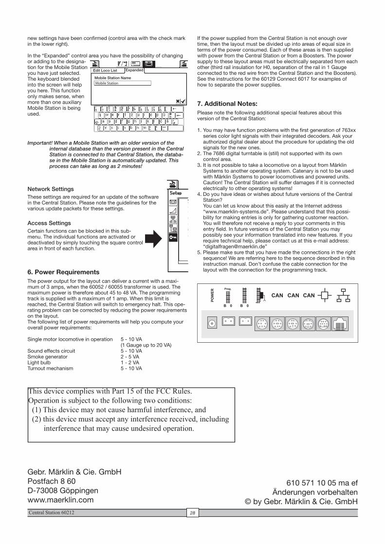
Central Station 60212 28
If the power supplied from the Central Station is not enough over time, then the layout must be divided up into areas of equal size in terms of the power consumed. Each of these areas is then supplied with power from the Central Station or from a Boosters. The power supply to these layout areas must be electrically separated from each other (third rail insulation for H0, separation of the rail in 1 Gauge connected to the red wire from the Central Station and the Boosters). See the instructions for the 60129 Connect 6017 for examples of how to separate the power supplies.
7. Additional Notes:Please note the following additional special features about this version of the Central Station:
1. You may have function problems with the first generation of 763xx series color light signals with their integrated decoders. Ask your authorized digital dealer about the procedure for updating the old signals for the new ones.
2. The 7686 digital turntable is (still) not supported with its own control area.
3. It is not possible to take a locomotive on a layout from Märklin Systems to another operating system. Catenary is not to be used with Märklin Systems to power locomotives and powered units. Caution! The Central Station will suffer damages if it is connected electrically to other operating systems!
4. Do you have ideas or wishes about future versions of the Central Station? You can let us know about this easily at the Internet address “www.maerklin-systems.de”. Please understand that this possi-bility for making entries is only for gathering customer reaction. You will therefore not receive a reply to your comments in this entry field. In future versions of the Central Station you may possibly see your information translated into new features. If you require technical help, please contact us at this e-mail address: “[email protected]”
5. Please make sure that you have made the connections in the right sequence! We are referring here to the sequence described in this instruction manual. Don’t confuse the cable connection for the layout with the connection for the programming track.
new settings have been confirmed (control area with the check mark in the lower right).
In the “Expanded” control area you have the possibility of changing or adding to the designa-tion for the Mobile Station you have just selected. The keyboard blended into the screen will help you here. This function only makes sense, when more than one auxiliary Mobile Station is being used.
Important! When a Mobile Station with an older version of the internal database than the version present in the Central Station is connected to that Central Station, the databa-se in the Mobile Station is automatically updated. This process can take as long as 2 minutes!
Network SettingsThese settings are required for an update of the software in the Central Station. Please note the guidelines for the various update packets for these settings.
Access SettingsCertain functions can be blocked in this sub-menu. The individual functions are activated or deactivated by simply touching the square control area in front of each function.
6. Power RequirementsThe power output for the layout can deliver a current with a maxi-mum of 3 amps, when the 60052 / 60055 transformer is used. The maximum power is therefore about 45 to 48 VA. The programming track is supplied with a maximum of 1 amp. When this limit is reached, the Central Station will switch to emergency halt. This ope-rating problem can be corrected by reducing the power requirements on the layout. The following list of power requirements will help you compute your overall power requirements:
Single motor locomotive in operation 5 - 10 VA (1 Gauge up to 20 VA)Sound effects circuit 5 - 10 VASmoke generator 2 - 5 VALight bulb 1 - 2 VATurnout mechanism 5 - 10 VA
Edit Loco List Expanded
Mobile Station NameMobile Station
This device complies with Part 15 of the FCC Rules.Operation is subject to the following two conditions: (1) This device may not cause harmful interference, and (2) this device must accept any interference received, including interference that may cause undesired operation.
Gebr. Märklin & Cie. GmbHPostfach 8 60D-73008 Göppingenwww.maerklin.com
610 571 10 05 ma ef Änderungen vorbehalten
© by Gebr. Märklin & Cie. GmbH