Embed Size (px)
Citation preview
IEC qualification testing of bifacial PV modules –Test conditions and test requirements
bifiPV Workshop26/27 May 2014, INES, Chambery
Dr. Werner Herrmann, René DüpontTÜV Rheinland Energie und Umwelt GmbH51101 Cologne, GermanyPhone: +49-221/806-2272Email: [email protected]
27.05.2014
2
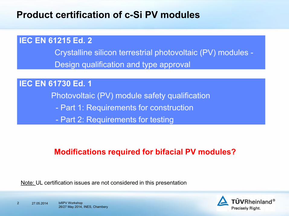
Product certification of c-Si PV modules
IEC EN 61215 Ed. 2Crystalline silicon terrestrial photovoltaic (PV) modules -Design qualification and type approval
IEC EN 61730 Ed. 1Photovoltaic (PV) module safety qualification - Part 1: Requirements for construction- Part 2: Requirements for testing
Note: UL certification issues are not considered in this presentation
Modifications required for bifacial PV modules?
27.05.2014 bifiPV Workshop26/27 May 2014, INES, Chambery
3
Specific test requirements for bifacial modules
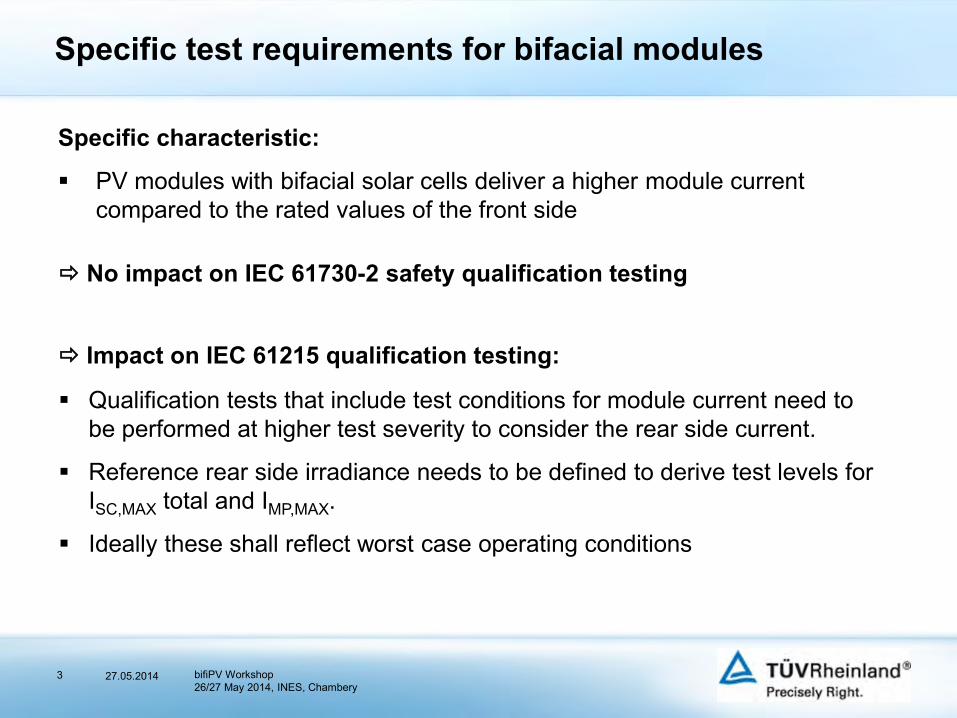
Specific characteristic:
PV modules with bifacial solar cells deliver a higher module current compared to the rated values of the front side
Qualification tests that include test conditions for module current need to be performed at higher test severity to consider the rear side current.
Reference rear side irradiance needs to be defined to derive test levels for ISC,MAX total and IMP,MAX.
Ideally these shall reflect worst case operating conditions
Impact on IEC 61215 qualification testing:
No impact on IEC 61730-2 safety qualification testing
27.05.2014 bifiPV Workshop26/27 May 2014, INES, Chambery
4
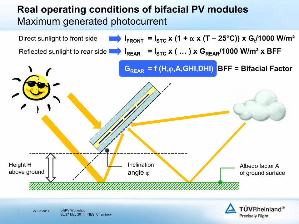
Real operating conditions of bifacial PV modulesMaximum generated photocurrentDirect sunlight to front side
Reflected sunlight to rear side
Albedo factor A of ground surface
Height H above ground
Inclinationangle
IFRONT = ISTC x (1 + x (T – 25°C)) x Gt/1000 W/m²IREAR = ISTC x ( … ) x GREAR/1000 W/m² x BFF
GREAR = f (H,,A,GHI,DHI) BFF = Bifacial Factor
27.05.2014 bifiPV Workshop26/27 May 2014, INES, Chambery
5
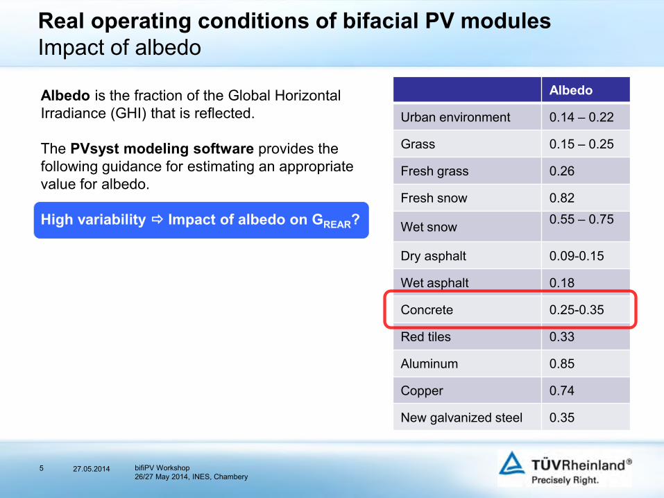
Real operating conditions of bifacial PV modulesImpact of albedo
Albedo is the fraction of the Global Horizontal Irradiance (GHI) that is reflected.
The PVsyst modeling software provides the following guidance for estimating an appropriate value for albedo.
High variability Impact of albedo on GREAR?
Albedo
Urban environment 0.14 – 0.22
Grass 0.15 – 0.25
Fresh grass 0.26
Fresh snow 0.82
Wet snow 0.55 – 0.75
Dry asphalt 0.09-0.15
Wet asphalt 0.18
Concrete 0.25-0.35
Red tiles 0.33
Aluminum 0.85
Copper 0.74
New galvanized steel 0.35
27.05.2014 bifiPV Workshop26/27 May 2014, INES, Chambery
6
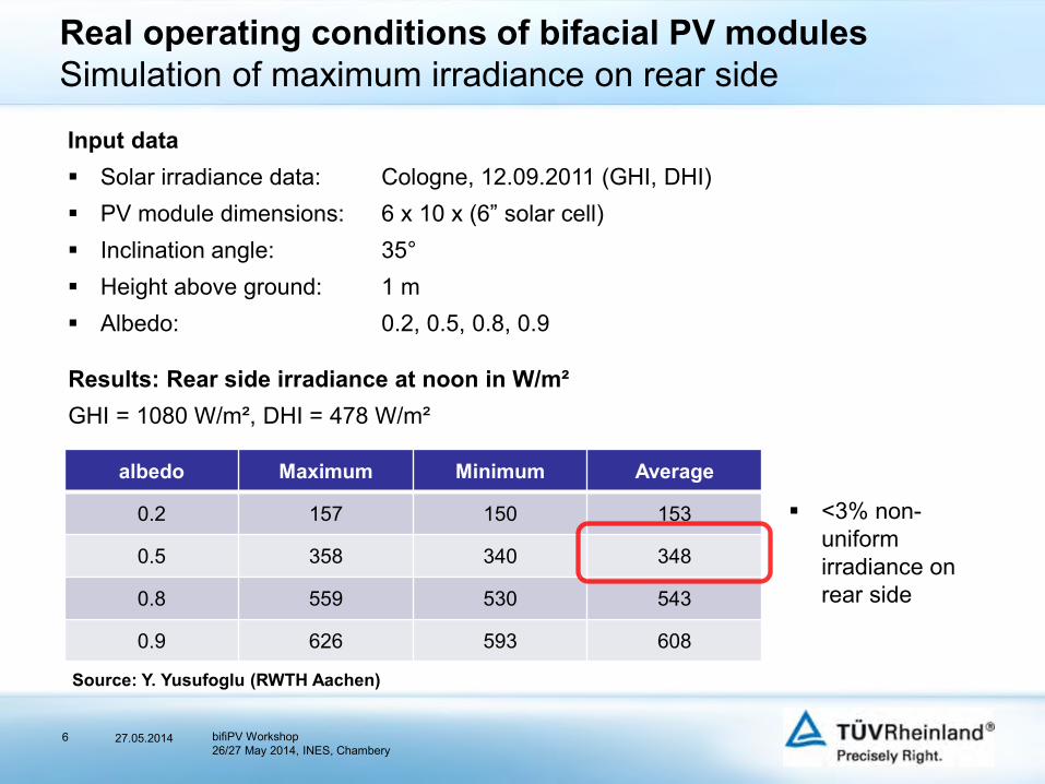
Real operating conditions of bifacial PV modulesSimulation of maximum irradiance on rear side
Source: Y. Yusufoglu (RWTH Aachen)
Input data Solar irradiance data: Cologne, 12.09.2011 (GHI, DHI) PV module dimensions: 6 x 10 x (6” solar cell) Inclination angle: 35° Height above ground: 1 m Albedo: 0.2, 0.5, 0.8, 0.9
Results: Rear side irradiance at noon in W/m²GHI = 1080 W/m², DHI = 478 W/m²
albedo Maximum Minimum Average
0.2 157 150 153
0.5 358 340 348
0.8 559 530 543
0.9 626 593 608
<3% non-uniform irradiance on rear side
27.05.2014 bifiPV Workshop26/27 May 2014, INES, Chambery
7
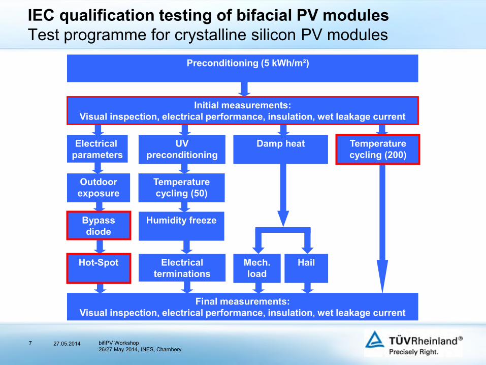
IEC qualification testing of bifacial PV modulesTest programme for crystalline silicon PV modules
Initial measurements: Visual inspection, electrical performance, insulation, wet leakage current
Preconditioning (5 kWh/m²)
Temperature cycling (200)
Electrical parameters
Outdoor exposure
Hot-Spot
UV preconditioning
Temperature cycling (50)
Humidity freeze
Electrical terminations
Damp heat
HailMech.load
Final measurements: Visual inspection, electrical performance, insulation, wet leakage current
Bypass diode
27.05.2014 bifiPV Workshop26/27 May 2014, INES, Chambery
8
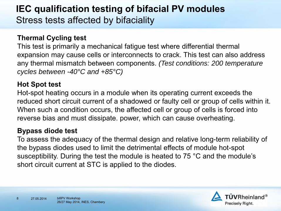
Thermal Cycling testThis test is primarily a mechanical fatigue test where differential thermal expansion may cause cells or interconnects to crack. This test can also address any thermal mismatch between components. (Test conditions: 200 temperature
cycles between -40°C and +85°C)
Hot Spot testHot-spot heating occurs in a module when its operating current exceeds the reduced short circuit current of a shadowed or faulty cell or group of cells within it. When such a condition occurs, the affected cell or group of cells is forced into reverse bias and must dissipate. power, which can cause overheating.
Bypass diode testTo assess the adequacy of the thermal design and relative long-term reliability of the bypass diodes used to limit the detrimental effects of module hot-spot susceptibility. During the test the module is heated to 75 °C and the module’s short circuit current at STC is applied to the diodes.
IEC qualification testing of bifacial PV modulesStress tests affected by bifaciality
27.05.2014 bifiPV Workshop26/27 May 2014, INES, Chambery
9
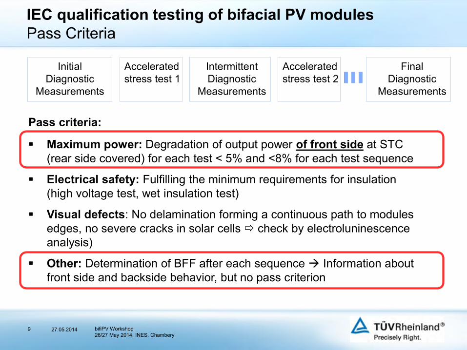
Accelerated stress test 2
IEC qualification testing of bifacial PV modulesPass Criteria
InitialDiagnostic
Measurements
Accelerated stress test 1
FinalDiagnostic
Measurements
IntermittentDiagnostic
Measurements
Pass criteria:
Maximum power: Degradation of output power of front side at STC (rear side covered) for each test < 5% and <8% for each test sequence
Electrical safety: Fulfilling the minimum requirements for insulation (high voltage test, wet insulation test)
Visual defects: No delamination forming a continuous path to modules edges, no severe cracks in solar cells check by electroluninescenceanalysis)
Other: Determination of BFF after each sequence Information about front side and backside behavior, but no pass criterion
27.05.2014 bifiPV Workshop26/27 May 2014, INES, Chambery
10
IEC qualification testing of bifacial PV modulesOutput power determination of bifacial PV modules
Rating of nominal output power (Global agreement within TÜV Rheinland Group)
Power rating/labelling of module type shall comply to nominal power of the front side only.
Front side output power at STC is measured by covering rear side with an opaque sheet.
Power rating of rear side is performed at STC or 400 W/m². This value is to be regarded as additional information on module label or datasheet.
27.05.2014 bifiPV Workshop26/27 May 2014, INES, Chambery
11
IEC qualification testing of bifacial PV modulesOutput power determination of bifacial PV modules
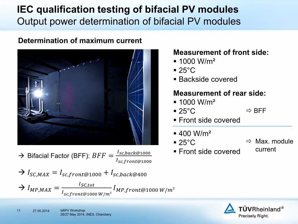
Measurement of front side: 1000 W/m² 25°C Backside covered
Measurement of rear side: 1000 W/m² 25°C Front side covered
400 W/m² 25°C Front side covered
Determination of maximum current
BFF
Max. modulecurrent
Bifacial Factor (BFF): 𝐵𝐹𝐹 =𝐼𝑠𝑐,𝑏𝑎𝑐𝑘@1000
𝐼𝑠𝑐,𝑓𝑟𝑜𝑛𝑡@1000
𝐼𝑆𝐶,𝑀𝐴𝑋 = 𝐼𝑠𝑐,𝑓𝑟𝑜𝑛𝑡@1000 + 𝐼𝑠𝑐,𝑏𝑎𝑐𝑘@400
𝐼𝑀𝑃,𝑀𝐴𝑋 =𝐼𝑆𝐶,𝑡𝑜𝑡
𝐼𝑠𝑐,𝑓𝑟𝑜𝑛𝑡@1000𝑊/𝑚²𝐼𝑀𝑃,𝑓𝑟𝑜𝑛𝑡@1000𝑊/𝑚²
27.05.2014 bifiPV Workshop26/27 May 2014, INES, Chambery
12
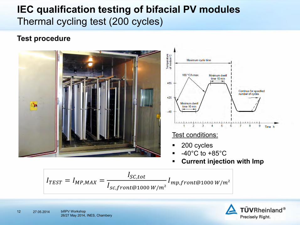
IEC qualification testing of bifacial PV modulesThermal cycling test (200 cycles)Test procedure
Test conditions: 200 cycles -40°C to +85°C Current injection with Imp
𝐼𝑇𝐸𝑆𝑇 = 𝐼𝑀𝑃,𝑀𝐴𝑋 =𝐼𝑆𝐶,𝑡𝑜𝑡
𝐼𝑠𝑐,𝑓𝑟𝑜𝑛𝑡@1000𝑊/𝑚²𝐼𝑚𝑝,𝑓𝑟𝑜𝑛𝑡@1000𝑊/𝑚²
27.05.2014 bifiPV Workshop26/27 May 2014, INES, Chambery
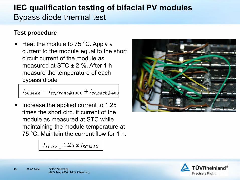
Heat the module to 75 °C. Apply a current to the module equal to the short circuit current of the module as measured at STC ± 2 %. After 1 h measure the temperature of each bypass diode
𝐼𝑆𝐶,𝑀𝐴𝑋 = 𝐼𝑠𝑐,𝑓𝑟𝑜𝑛𝑡@1000 + 𝐼𝑠𝑐,𝑏𝑎𝑐𝑘@400
Increase the applied current to 1.25 times the short circuit current of the module as measured at STC while maintaining the module temperature at 75 °C. Maintain the current flow for 1 h.
𝐼𝑇𝐸𝑆𝑇2 =1.25 𝑥 𝐼𝑆𝐶,𝑀𝐴𝑋
13
IEC qualification testing of bifacial PV modulesBypass diode thermal test
Test procedure
27.05.2014 bifiPV Workshop26/27 May 2014, INES, Chambery
14
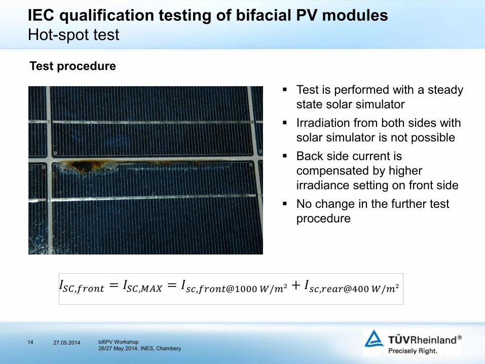
IEC qualification testing of bifacial PV modulesHot-spot test
Test is performed with a steady state solar simulator
Irradiation from both sides with solar simulator is not possible
Back side current is compensated by higher irradiance setting on front side
No change in the further test procedure
Test procedure
𝐼𝑆𝐶,𝑓𝑟𝑜𝑛𝑡 = 𝐼𝑆𝐶,𝑀𝐴𝑋 = 𝐼𝑠𝑐,𝑓𝑟𝑜𝑛𝑡@1000𝑊/𝑚² + 𝐼𝑠𝑐,𝑟𝑒𝑎𝑟@400𝑊/𝑚²
27.05.2014 bifiPV Workshop26/27 May 2014, INES, Chambery
15
Conclusions
Test standard IEC 61215 is applicable for bifacial PV modules. Just test levels of current driven tests need to be modified: a) Thermal cycling 200, b) Hot-Spot test, c) Bypass diode thermal test
Test current is related to 1000 W/m² front side irradiation and 400 W/m² rear side irradiation.
Assumption of 400 W/m² irradiation on rear side has been confirmed by simulation study with real weather data.
Power rating of a bifacial PV module type shall be referenced to the front side only. Power contribution of rear side shall be informative.
27.05.2014 bifiPV Workshop26/27 May 2014, INES, Chambery
27.05.201416
Thank you for your attention.
bifiPV Workshop26/27 May 2014, INES, Chambery
17
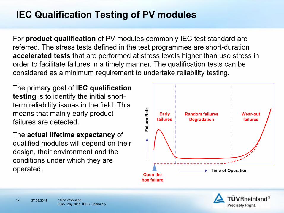
For product qualification of PV modules commonly IEC test standard are referred. The stress tests defined in the test programmes are short-duration accelerated tests that are performed at stress levels higher than use stress in order to facilitate failures in a timely manner. The qualification tests can be considered as a minimum requirement to undertake reliability testing.
The primary goal of IEC qualification testing is to identify the initial short-term reliability issues in the field. This means that mainly early product failures are detected.
The actual lifetime expectancy of qualified modules will depend on their design, their environment and the conditions under which they are operated. Time of Operation
Open the box failure
Early failures
Random failures Degradation
Wear-out failures
Failu
re R
ate
IEC Qualification Testing of PV modules
27.05.2014 bifiPV Workshop26/27 May 2014, INES, Chambery
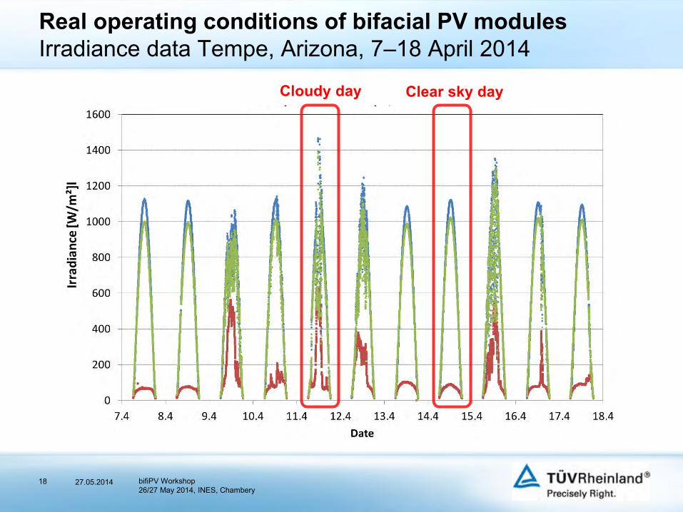
18
Real operating conditions of bifacial PV modulesIrradiance data Tempe, Arizona, 7–18 April 2014
Clear sky dayCloudy day
27.05.2014 bifiPV Workshop26/27 May 2014, INES, Chambery
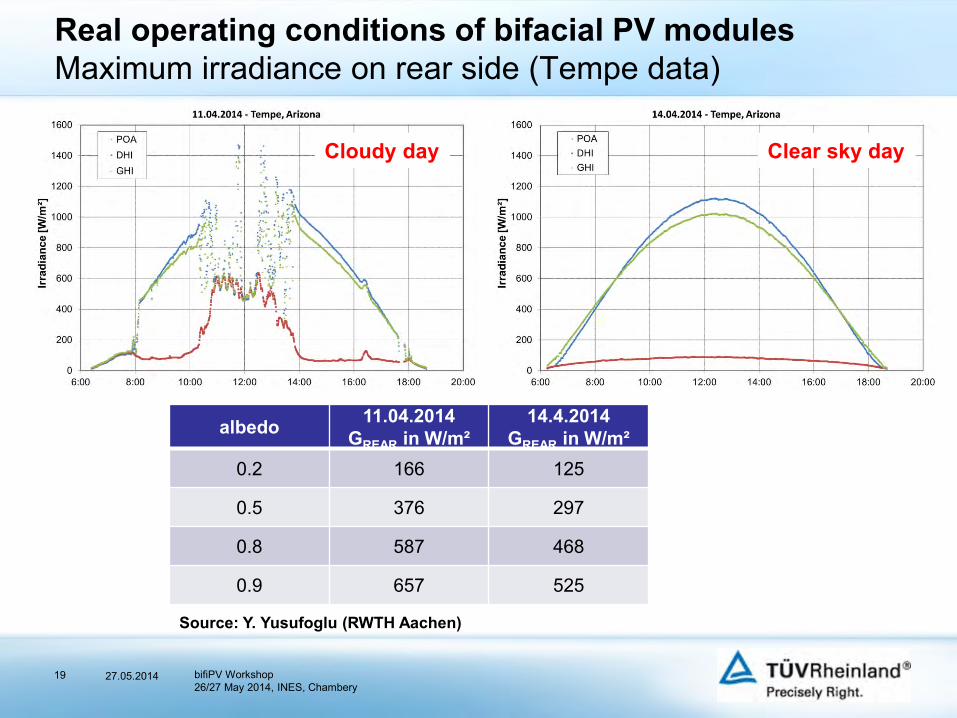
19
Real operating conditions of bifacial PV modulesMaximum irradiance on rear side (Tempe data)
albedo 11.04.2014GREAR in W/m²
14.4.2014GREAR in W/m²
0.2 166 125
0.5 376 297
0.8 587 468
0.9 657 525
Source: Y. Yusufoglu (RWTH Aachen)
Cloudy day Clear sky day
27.05.2014 bifiPV Workshop26/27 May 2014, INES, Chambery