Embed Size (px)
DESCRIPTION
http://www.dungs.com/fileadmin/media/Downloads/DBs_BMAs/225912.pdf?1290007620
Citation preview
1 … 8
M/CD · 版本 Edition 02.10·号码 225 912
Betriebs- und Montagean-leitung
Luftdruckwächter LGW … A2Luftdruckwächter mit PrüftasteLGW … A2P
Operation and assembly instructions
Air pressure switchLGW ... A2Air pressure switch with test buttonLGW ... A2P
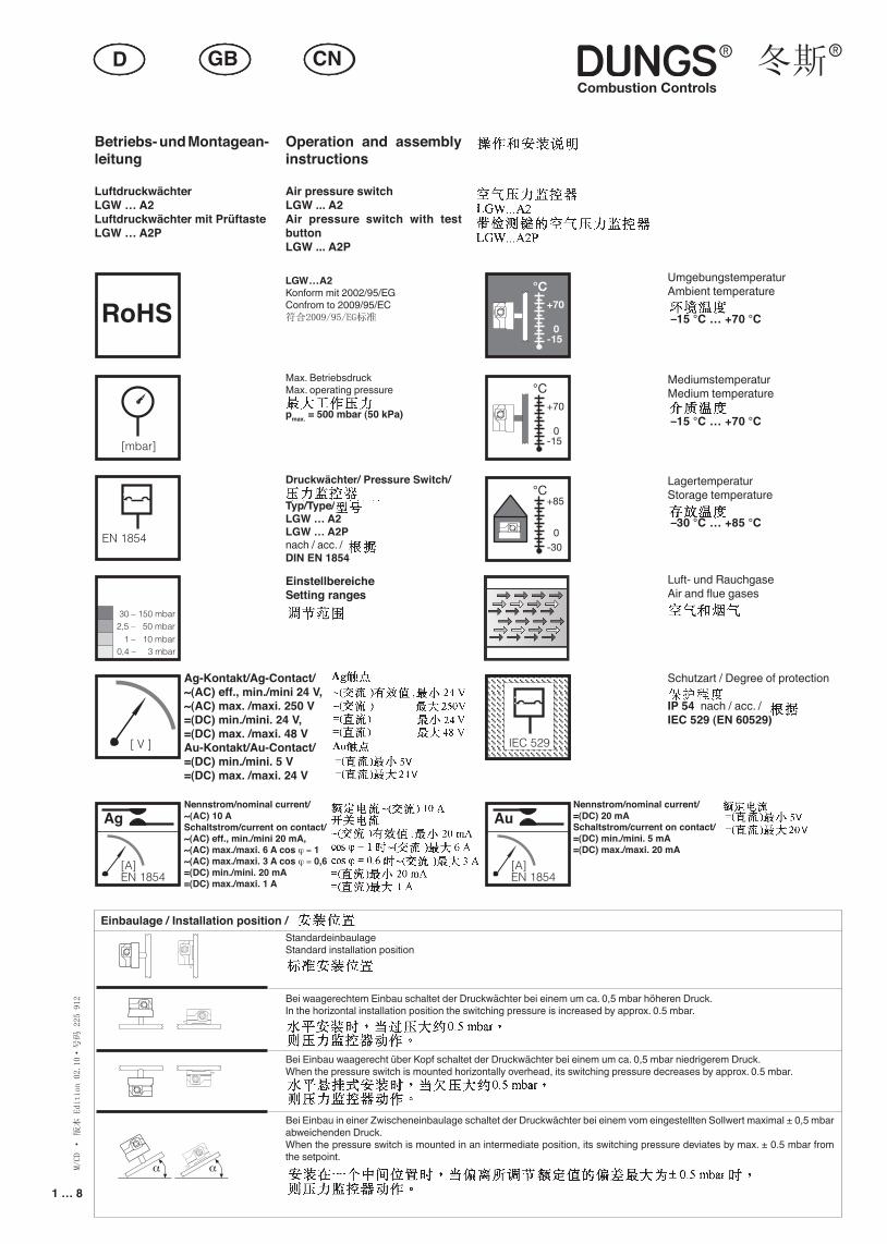
Max. BetriebsdruckMax. operating pressure
pmax. = 500 mbar (50 kPa)
LGW…A2Konform mit 2002/95/EGConfrom to 2009/95/EC符合2009/95/EG标准
Druckwächter/ Pressure Switch/
Typ/Type/LGW … A2LGW … A2Pnach / acc. / DIN EN 1854
UmgebungstemperaturAmbient temperature
–15 °C … +70 °C
MediumstemperaturMedium temperature
–15 °C … +70 °C
LagertemperaturStorage temperature
–30 °C … +85 °C
Luft- und RauchgaseAir and flue gases
Schutzart / Degree of protection
IP 54 nach / acc. / IEC 529 (EN 60529)
EinstellbereicheSetting ranges
Nennstrom/nominal current/~(AC) 10 ASchaltstrom/current on contact/~(AC) eff., min./mini 20 mA,~(AC) max./maxi. 6 A cos ϕ = 1~(AC) max./maxi. 3 A cos ϕ = 0,6 =(DC) min./mini. 20 mA=(DC) max./maxi. 1 A
[mbar]
2,5 – 50 mbar
0,4 – 3 mbar
30 – 150 mbar
1 – 10 mbar
[ V ] IEC 529IEC 529
°C
0
+85
-30
0
+70
-15
°C
0
+70
-15
°C
Ag
[A]EN 1854
EN 1854
StandardeinbaulageStandard installation position
Bei waagerechtem Einbau schaltet der Druckwächter bei einem um ca. 0,5 mbar höheren Druck.In the horizontal installation position the switching pressure is increased by approx. 0.5 mbar.
Bei Einbau waagerecht über Kopf schaltet der Druckwächter bei einem um ca. 0,5 mbar niedrigerem Druck.When the pressure switch is mounted horizontally overhead, its switching pressure decreases by approx. 0.5 mbar.
Bei Einbau in einer Zwischeneinbaulage schaltet der Druckwächter bei einem vom eingestellten Sollwert maximal ± 0,5 mbar abweichenden Druck.When the pressure switch is mounted in an intermediate position, its switching pressure deviates by max. ± 0.5 mbar from the setpoint.
Einbaulage / Installation position /
Au
[A]EN 1854
Nennstrom/nominal current/=(DC) 20 mASchaltstrom/current on contact/=(DC) min./mini. 5 mA=(DC) max./maxi. 20 mA
Ag-Kontakt/Ag-Contact/~(AC) eff., min./mini 24 V, ~(AC) max. /maxi. 250 V=(DC) min./mini. 24 V, =(DC) max. /maxi. 48 VAu-Kontakt/Au-Contact/=(DC) min./mini. 5 V =(DC) max. /maxi. 24 V
α αα α
α α
α α
RoHS
2 … 8
M/CD · 版本 Edition 02.10·号码 225 912
3 … 8
G 1/4
7 Nm
1,2 Nm
A
B
Made in Germany–
+
+
Made in Germany–
+
12
Made in Germany
2
–
–
+
–
Made in Germany
–
+
2
3
1
2
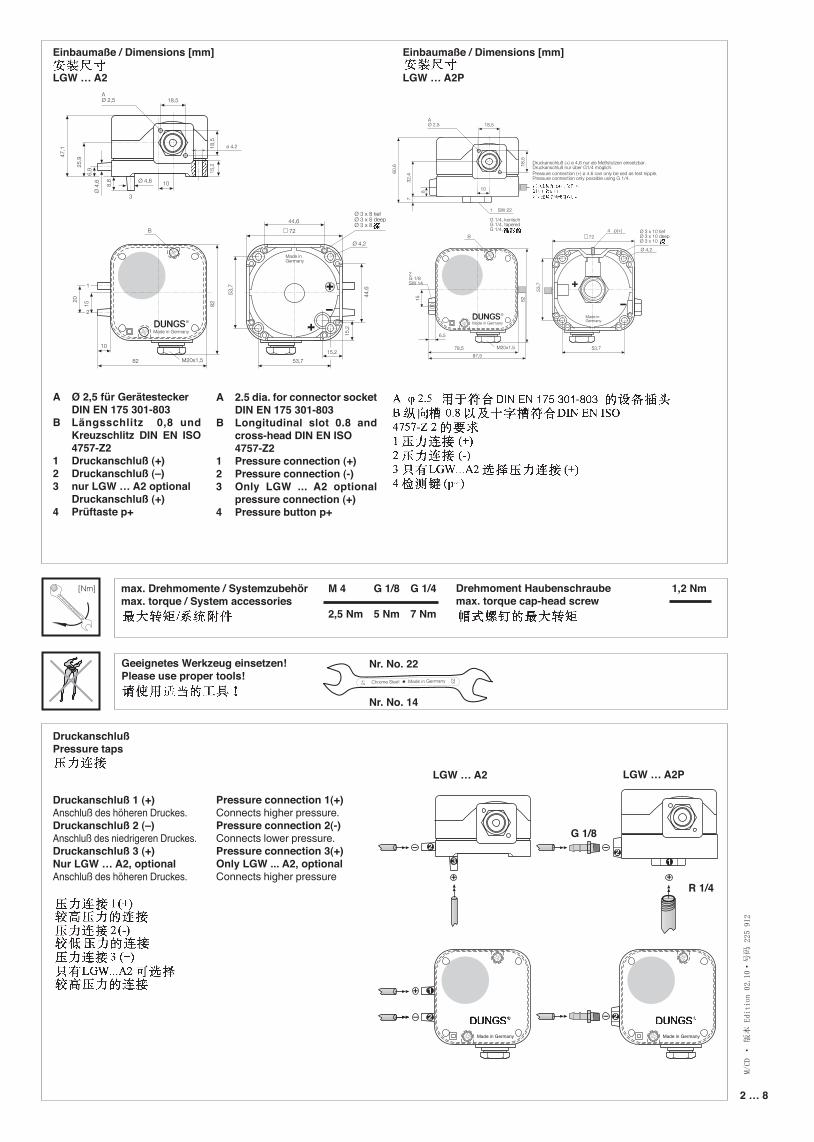
Einbaumaße / Dimensions [mm]
LGW … A2
Einbaumaße / Dimensions [mm]
LGW … A2P
DruckanschlußPressure taps
Druckanschluß 1 (+) Anschluß des höheren Druckes.Druckanschluß 2 (–)Anschluß des niedrigeren Druckes. Druckanschluß 3 (+) Nur LGW … A2, optionalAnschluß des höheren Druckes.
max. Drehmomente / Systemzubehörmax. torque / System accessories
Geeignetes Werkzeug einsetzen! Please use proper tools!
Drehmoment Haubenschraubemax. torque cap-head screw
M 4
2,5 Nm
G 1/8
5 Nm
G 1/8
A Ø 2,5 für Gerätestecker DIN EN 175 301-803B Längsschlitz 0,8 und
Kreuzschlitz DIN EN ISO 4757-Z2
1 Druckanschluß (+)2 Druckanschluß (–)3 nur LGW … A2 optional Druckanschluß (+)4 Prüftaste p+
A 2.5 dia. for connector socket DIN EN 175 301-803
B Longitudinal slot 0.8 and cross-head DIN EN ISO
4757-Z21 Pressure connection (+)2 Pressure connection (-)3 Only LGW ... A2 optional
pressure connection (+)4 Pressure button p+
Pressure connection 1(+)Connects higher pressure.Pressure connection 2(-)Connects lower pressure. Pressure connection 3(+)Only LGW ... A2, optionalConnects higher pressure
Nr. No. 22
Nr. No. 14
LGW … A2 LGW … A2P
R 1/4
[Nm]
18
19
2123
2 … 8 3 … 8
M/CD · 版本 Edition 02.10·号码 225 912
22
24
22
24
[Nm] t ≤ 10 s
[Nm] t ≤ 10 s
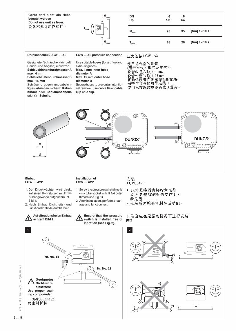
EinbauLGW … A2P
1. Der Druckwächter wird direkt auf einen Rohrstutzen mit R 1/4 Außengewinde aufgeschraubt.
Bild 1.2. Nach Einbau Dichtheits- und
Funktionskontrolle durchführen.
Auf vibrationsfreien Einbau achten! Bild 2.
1
Installation ofLGW … A2P
1. Screw the pressure switch directly on a tube socket with R 1/4 outer thread (see Fig. 1).
2. After installation, perform a leak-age and function test.
Ensure that the pressure switch is installed free of vibration (see Fig. 2).
2
Geeignetes Dichtmittel einsetzen!
Use proper seal-ing compounds!
Nr. No. 22
Nr. No. 14
Druckanschluß LGW … A2
Geeignete Schläuche (für Luft, Rauch- und Abgase) einsetzen. Schlauchinnendurchmesser Amax. 4 mmSchlauchaußendurchmesser Bmax. 15 mm Schläuche gegen unbeabsich-tigtes Abziehen sichern: Kabel-binder oder Schlauchschelle oder Ω - Schelle.
LGW ... A2 pressure connection
Use suitable hoses (for air, flue and exhaust gases)Max. 4 mm inner hose diameter AMax. 15 mm outer hose diameter BSecure hoses to prevent unintentio-nal removal: use cable tie or cable clip or Ω clip.
A
B
Made in Germany–
+
+Made in Germany
–
+
12
Made in Germany
2
–
–
+
–
Made in Germany
–
+
2
3
1
2
A
B
Made in Germany–
+
+
Made in Germany–
+
12
Made in Germany
2
–
–
+
–
Made in Germany
–
+
2
3
1
2
A
B
Made in Germany–
+
+
Made in Germany–
+
12
Made in Germany
2
–
–
+
–
Made in Germany
–
+
2
3
1
2
DNRp
Mmax.
Tmax.
81/4
35
20
61/8
25
15
Tmax.
Mmax.
Mmax.
Gerät darf nicht als Hebel benutzt werdenDo not use unit as lever.
4 … 8
M/CD · 版本 Edition 02.10·号码 225 912
5 … 8
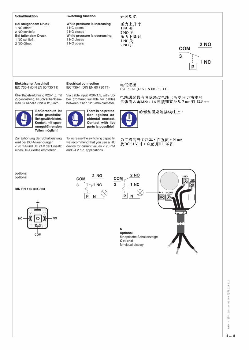
Electrical connectionIEC 730-1 (DIN EN 60 730 T1)
Via cable input M20x1,5, with rub-ber grommet suitable for cables between 7 and 12.5 mm diameter.
There is no protec-tion against ac-cidental contact. Contact with live parts is possible!
To increase the switching capacity, we recommend that you use a RC device for current values < 20 mA and 24 V d.c. applications.
Elektrischer AnschlußIEC 730-1 (DIN EN 60 730 T1)
Über Kabeleinführung M20x1,5, mit Zugentlastung, an Schraubenklem-men für Kabel ø 7 bis ø 12,5 mm.
Berührschutz ist nicht grundsätz-lich gewährleistet, Kontakt mit span-nungsführenden Teilen möglich!
Zur Erhöhung der Schaltleistung wird bei DC-Anwendungen < 20 mA und DC 24 V der Einsatz eines RC-Gliedes empfohlen.
Schaltfunktion
Bei steigendem Druck1 NC öffnet2 NO schließtBei fallendem Druck1 NC schließt2 NO öffnet
Switching function
While pressure is increasing1 NC opens2 NO closesWhile pressure is decreasing1 NC closes2 NO opens
p
COMNO
NC
2
13
COMNO
NC
2
1
p
3
N
COMNO
NC
2
1
p
3
N
1 NC2 NO
3 COMN
optionaloptional
DIN EN 175 301-803
Noptionalfür optische Schaltanzeige Optionalfor visual display
NC NO1 2
3
COM
p
COMNO
NC
2
13
COMNO
NC
2
1
p
3
N
COMNO
NC
2
1
p
3
N
p
COMNO
NC
2
13
COMNO
NC
2
1
p
3
N
COMNO
NC
2
1
p
3
N
4 … 8 5 … 8
M/CD · 版本 Edition 02.10·号码 225 912
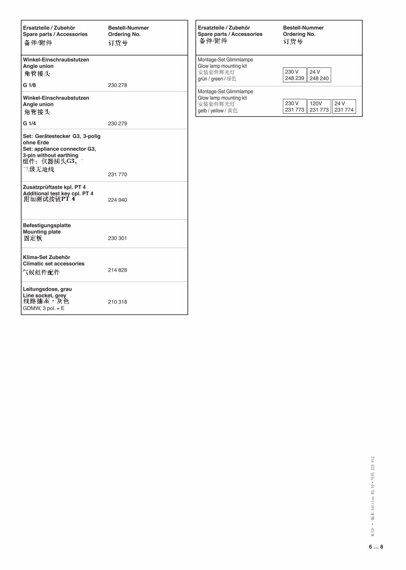
Setting the pressure switch Dismount the hood using a suitable tool, e.g. screwdriver no. 3 or PZ2, Fig. 1. Remove hood.
There is no protection against accidental contact.
Contact with live parts is possi-ble.
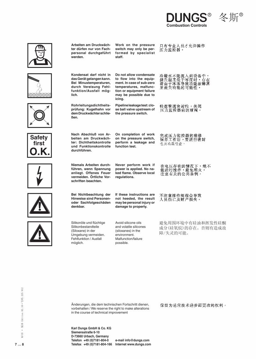
Setting LGW … A2, LGW … A2P Set the pressure switch at the setting wheel to the specified pressure setpoint using the scale, Fig. 2.Follow the instructions of the burner manufacturer!Pressure switch switches as pres-sure increases: Set to left limit line ↑. Pressure switch switches as pressure reduces: Set to right limit line ↓.Remount hood!
Einstellung des DruckwächtersHaube mit geeignetem Werkzeug demontieren, Schraubendreher No. 3 bzw. PZ 2, Bild 1.Haube abnehmen.
Berührschutz ist nicht grundsätzlich gewährt,
Kontakt mit spannungsführen-den Teilen möglich.
Einstellung LGW…A2, LGW…A2PDruckwächter am Einstellrad mit Skala auf vorgeschriebenen Drucksollwert einstellen, Bild 2.Anleitung des Brennerherstel-lers beachten!Druckwächter schaltet bei stei-gendem Druck: Einstellung auf die linke Begrenzungslinie↑. Druckwächter schaltet bei fal-lendem Druck: Einstellung auf die rechte Begrenzungslinie ↓.Haube wieder aufsetzen!
1
2 LGW … A2 2 LGW … A2P
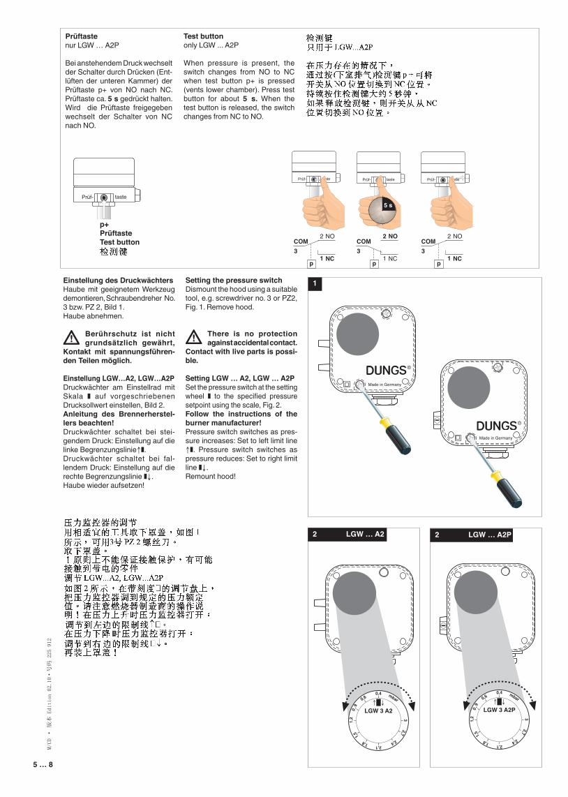
Prüftastenur LGW … A2P
Bei anstehendem Druck wechselt der Schalter durch Drücken (Ent-lüften der unteren Kammer) der Prüftaste p+ von NO nach NC. Prüftaste ca. 5 s gedrückt halten. Wird die Prüftaste freigegeben wechselt der Schalter von NC nach NO.
Test buttononly LGW ... A2P
When pressure is present, the switch changes from NO to NC when test button p+ is pressed (vents lower chamber). Press test button for about 5 s. When the test button is released, the switch changes from NC to NO.
Made in Germany Made in Germany
0,4
2,1
0,6
0,9
1,2
1,5
1,8 2,4
2,73
mbar
LGW 3 A2P↑ ↓
0,4
2,1
0,6
0,9
1,2
1,5
1,8 2,4
2,73
mbar
LGW 3 A2↑ ↓
Made in Germany Made in Germany
0,4
2,1
0,6
0,9
1,2
1,5
1,8 2,4
2,73
mbar
LGW 3 A2P↑ ↓
0,4
2,1
0,6
0,9
1,2
1,5
1,8 2,4
2,73
mbar
LGW 3 A2↑ ↓
Made in Germany Made in Germany
0,4
2,1
0,6
0,9
1,2
1,5
1,8 2,4
2,73
mbar
LGW 3 A2P↑ ↓
0,4
2,1
0,6
0,9
1,2
1,5
1,8 2,4
2,73
mbar
LGW 3 A2↑ ↓
Made in Germany Made in Germany
0,4
2,1
0,6
0,9
1,2
1,5
1,8 2,4
2,73
mbar
LGW 3 A2P↑ ↓
0,4
2,1
0,6
0,9
1,2
1,5
1,8 2,4
2,73
mbar
LGW 3 A2↑ ↓
Prüf- taste Prüf- taste Prüf- taste Prüf- taste
5 s
p
COMNO
NC
2
13
p
COMNO
NC
2
13
p
COMNO
NC
2
13
Prüf- taste Prüf- taste Prüf- taste Prüf- taste
5 s
p
COMNO
NC
2
13
p
COMNO
NC
2
13
p
COMNO
NC
2
13
p+PrüftasteTest button
6 … 8
M/CD · 版本 Edition 02.10·号码 225 912
7 … 8
Ersatzteile / ZubehörSpare parts / Accessories
Montage-Set Glimmlampe Glow lamp mounting kit 安装套件辉光灯grün / green / 绿色
Montage-Set Glimmlampe Glow lamp mounting kit 安装套件辉光灯gelb / yellow / 黄色
Bestell-NummerOrdering No.
230 278
230 279
231 770
224 940
230 301
214 828
210 318
Ersatzteile / ZubehörSpare parts / Accessories
Winkel-EinschraubstutzenAngle union
G 1/8
Winkel-EinschraubstutzenAngle union
G 1/4
Set: Gerätestecker G3, 3-polig ohne ErdeSet: appliance connector G3, 3-pin without earthing
Zusatzprüftaste kpl. PT 4Additional test key cpl. PT 4
BefestigungsplatteMounting plate
Klima-Set ZubehörClimatic set accessories
Leitungsdose, grauLine socket, grey
GDMW, 3 pol. + E
Bestell-NummerOrdering No.
230 V248 239
230 V231 773
24 V248 240
120V231 773
24 V231 774
6 … 8 7 … 8
M/CD · 版本 Edition 02.10·号码 225 912
Rohrleitungsdichtheits-prüfung: Kugelhahn vor dem Druckwächter schlie-ßen.
Nach Abschluß von Ar-beiten am Druckwäch-ter: Dichtheitskontrolle und Funktionskontrolle durchführen.
Niemals Arbeiten durch-führen, wenn Spannung anliegt. Offenes Feuer vermeiden. Örtliche Vor-schriften beachten.
Bei Nichtbeachtung der Hinweise sind Personen- oder Sachfolgeschäden denkbar.
Pipeline leakage test: clo-se ball valve upstream of the pressure switch.
On completion of work on the pressure switch, perform a leakage and function test.
Never perform work if power is applied. No na-ked flame. Observe local regulations.
If these instructions are not heeded, the result may be personal injury or damage to property.
Kondensat darf nicht in das Gerät gelangen kann. Bei Minustemperaturen, durch Vereisung Fehl-funktion/Ausfall mög-lich.
Do not allow condensate to flow into the equip-ment. In case of sub-zero temperatures, malfunc-tion or equipment failure may be possible due to icing.
Arbeiten am Druckwäch-ter dürfen nur von Fach-personal durchgeführt werden.
Work on the pressure switch may only be per-formed by specialist staff.
Safetyfirst
O.K.
Änderungen, die dem technischen Fortschritt dienen, vorbehalten / We reserve the right to make alterations in the course of technical improvement
Karl Dungs GmbH & Co. KG Siemensstraße 6-10 D-73660 Urbach, GermanyTelefon +49 (0)7181-804-0Telefax +49 (0)7181-804-166
e-mail [email protected] www.dungs.com
Silikonöle und flüchtige Silikonbestandteile (Siloxane) in der Umgebung vermeiden. Fehlfunktion / Ausfall möglich.
Avoid silicone oils and volatile silicones (siloxanes) in the environment. Malfunction/failure possible.
避免周围环境中有硅油和挥发性硅酮成分(硅氧烷)的存在。否则有造成故障/失灵的可能。
8 … 8
M/CD · 版本 Edition 02.10·号码 225 912
Die Druckgeräterichtlinie (PED) und die Richtlinie über die Gesamtener-gieeffizienz von Gebäuden (EPBD) fordern eine regel-mässige Überprüfung von Heizungsanlagen zur lang-fristigen Sicherstellung von hohen Nutzungsgraden und somit geringster Um-weltbelastung. Es besteht die Notwendigkeit sicher-heitsrelevante Komponen-ten nach Erreichen ihrer Nutzungsdauer auszutau-schen. Diese Empfehlung gilt nur für Heizungsan-lagen und nicht für Ther-mprozessanwendungen. DUNGS empfiehlt den Austausch gemäss fol-gender Tabelle:
按照压力器械指令(PED)和建筑物总能源效率指令(EPBD)的要求,要对采暖设备定期进行检查,以便长期确保高度的利用率和最低的环境负荷。对于和安全相关的组件,当达到其使用期限时,要予以更换。此建议仅适用于采暖设备,而不适用于工业加热过程应用场合。东斯公司建议根据以下表格实施更换工作:
Sicherheitsrelevante KomponenteSafety relevant component和安全相关的组件
NUTZUNGSDAUERDUNGS empfiehlt den Austausch nach:USEFUL LIFEDUNGS recommends replacement after:使用期限东斯公司建议更换按照:
SchaltspieleOperating cycles操作循环次数
Ventilprüfsysteme / Valve proving systems 阀门检漏系统
10 Jahre/years 10年 250.000
Druckwächter / Pressure switch / 调压阀 10 Jahre/years 10年 N/AFeuerungsmanager mit FlammenwächterAutomatic burner control with flame safe guard带火焰调节器的自动燃烧器
10 Jahre/years 10年 250.000
UV-FlammenfühlerFlame detector (UV probes)紫外线火焰传感器
10.000 h Betriebsstunden/Operating hours / 工作小时
Gasdruckregelgeräte / Gas pressure regulators燃气压力开关
15 Jahre/years 15年 N/A
Gasventil mit Ventilprüfsystem / Gas valve with valve testing system带阀门检漏系统的燃气阀
nach erkanntem Fehlerafter error detection按照发现的错误
Gasventil ohne Ventilprüfsystem* / Gas valve without valve testing system*无阀门检漏系统的燃气阀*
10 Jahre/years 10年 250.000
Min. Gasdruckwächter / Low gas pressure switch最小燃气调压阀
10 Jahre/years 10年 N/A
Sicherheitsabblaseventil / Pressure relief valve安全阀
10 Jahre/years 10年 N/A
Gas-Luft-Verbundsysteme / Gas-air-ratio control system燃气空气联合系统
10 Jahre/years 10年 N/A
* Gasfamilien I, II, III / Gas families I, II, III N/A kann nicht verwendet werden / not applicable / N/A - 不适用 *I, II, III类燃气
The Pressure Equipment Directive (PED) and the Energy Performance of Buildings Directive (EPBD) require a periodic inspec-tion of heating appliances in order to ensure a high degree of efficiency over a long term and, consequent-ly, the least environmental pollution. It is necessary to replace safety-relevant components after they have reached the end of their useful life. This rec-ommendation applies only to heating appliances and not to industrial heating processes. DUNGS rec-ommends replacing such components according to the following table:
Karl Dungs GmbH & Co. KG Siemensstraße 6-10 D-73660 Urbach, GermanyTelefon +49 (0)7181-804-0Telefax +49 (0)7181-804-166
e-mail [email protected] www.dungs.com