Embed Size (px)
Citation preview
CHAPTER I
INTRODUCTION
Electricity generation is the process of harnessing electrical power from
other sources of energy. Electricity transmission, distribution and electrical power
storage and recovery using pumped-storage methods are other processes
normally carried out by the electric power industry.
Power plants or power stations generate electricity by using
electromechanical generators. These generators are driven by heat engines
which are fueled by combustion or nuclear fission. Other means like the kinetic
energy from wind and flowing water are also viable options for electricity
generation. The most common types of power stations are nuclear power plant,
geothermal power plant, hydroelectric power plant, combine cycle power plant
and the diesel electric power plant which will be the main focus of this design
project.
Since the invention of diesel engine at the end of the nineteenth century,
this engine has found major applications either as a peak or as continuous
source of electric power due to its excellent qualities of operation and economy.
The diesel plants are more efficient than any other heat engines of comparable
sizes. First, it is cheap in cost. It can be started quickly and brought into service.
Its manufacturing periods are short and therefore, a diesel station may be rapidly
extended to keep pace with load growth by adding generating units of suitable
sizes.
1
In a diesel electric power plant, diesel engine is used as the prime mover.
The diesel fuel burns inside the engine and the products of this combustion act
as the working fluid to produce the mechanical energy. The diesel engine then
drives the alternator to convert the mechanical energy into electrical energy.
Such power stations are only used to produce small power, because of the
considerably high price of diesel.
Existing diesel power stations here in the Philippines offers a good
reference for this study. The 225 MW Bauang medium-speed bunker-fired diesel
power plant is one of the largest bunker-fired diesel power generation facilities in
the world. It has the highest capacity among all the diesel electric power plants
here in the Philippines operating under a 15 year Build-Operate-Transfer (BOT)
agreement. It is located approximately 255 kilometers north of Manila in
Payocpoc Sur, Bauang La Union. Other notable DEPPs in the Philippines are the
11 MW Bohol Diesel Power Plant in Tagbilaran, Bohol and the 75 MW Panay
Diesel Power Plant located in Iloilo City.
The researchers propose of establishing a Diesel Electric Power Plant
(DEPP) at Brgy. Locloc, Bauan, Batangas that will supply electricity to Bauan and
other nearby municipalities. The province of Batangas is located at the southern
tip of Luzon. It is one-hundred twenty kilometers away from Metro Manila through
a modernized expressway. A lot of large scale industries and modernized
commercial establishments can be found in the province.
2
Since the proposed location is near the coastal area, the water supply and
the cooling system of the plant will not be a problem. Other factors like fuel
transportation and the like will also not be much of an issue. The main objective
of the construction of the power plant in Locloc, Bauan, Batangas is to provide
and generate enough electricity to cope up with the increasing demands of the
people for a better way of living and economic advancements.
After a comprehensive survey of the load demands of Bauan and 10 other
nearby municipalities, namely, Agoncillo, Alitagtag, Calaca, Cuenca, Lemery,
Mabini, San Luis, San Nicolas, Sta. Teresita and Taal, the following load
demands for the year 2009 to 2013 was obtained:
3

Table 1. Historical Load Demands of Municipalities
4
Municipalities
Load Demands (kW-hr)
2009 2010 2011 2012 2013
Agoncillo 7,281,081 7,731,959 8,182,837 8,633,715 7,957,398
Alitagtag 60,859,471.82 69,988,392.59 80,486,651.48 92,559,649.20
Bauan 37,914,721 37,908,337 43,081,375 46,204,496.76
Calaca 24,754,058 26,244,091 27,734,124 29,224,157 30,714,190
Cuenca 122,868,953.73 141,299,296.79 162,494,191.30 186,868,320.00
Lemery 29,279,849 33,398,348 31,531,465 32,643,483 31,713,286.25
Mabini 151,147,129 173,819,199 199,892,079 229,875,890.40
San Luis 7,565,409 8,985,330 8,677,323 8,970,158 8,549,555
San Nicolas 4,373,104 5,065,873 4,930,757 4,537,849 4,726,895.75
Sta. Teresita 3,820,507 4,380,060 4,173,034 4,207,120 4,145,180.25
Taal 15,537,074 17,854,530 17,144,951 17,713,587 17,062,535.50

To obtain the capacity of the diesel electric power plant, an assumption of 13% annual load increase was made. Using a 10
year load projection the following data were obtained:
5
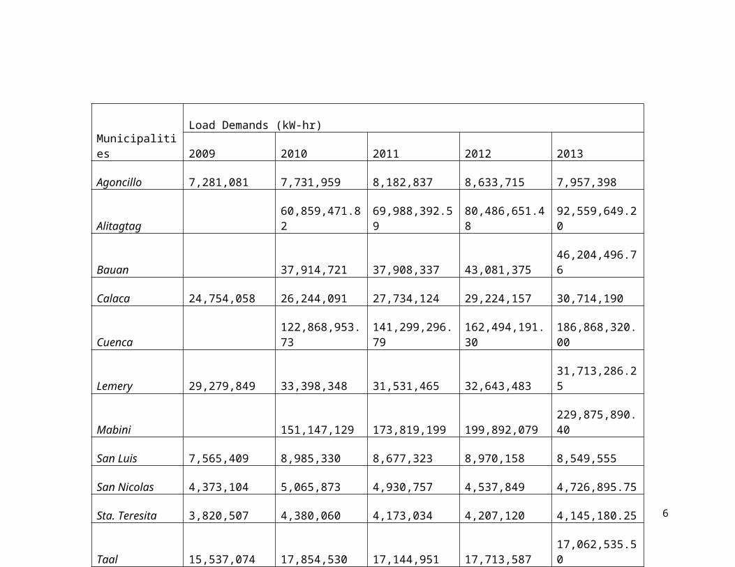
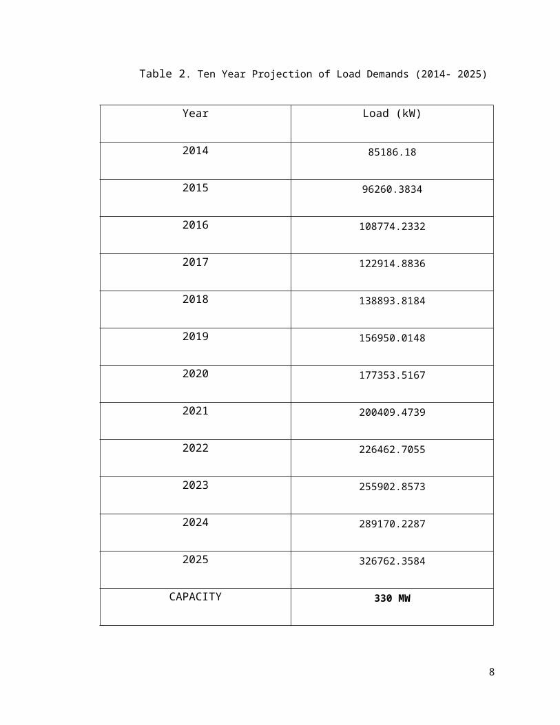
Table 2. Ten Year Projection of Load Demands (2014- 2025)
Year Load (kW)
2014 85186.18
2015 96260.3834
2016 108774.2332
2017 122914.8836
2018 138893.8184
2019 156950.0148
2020 177353.5167
2021 200409.4739
2022 226462.7055
2023 255902.8573
2024 289170.2287
2025 326762.3584
CAPACITY 330 MW
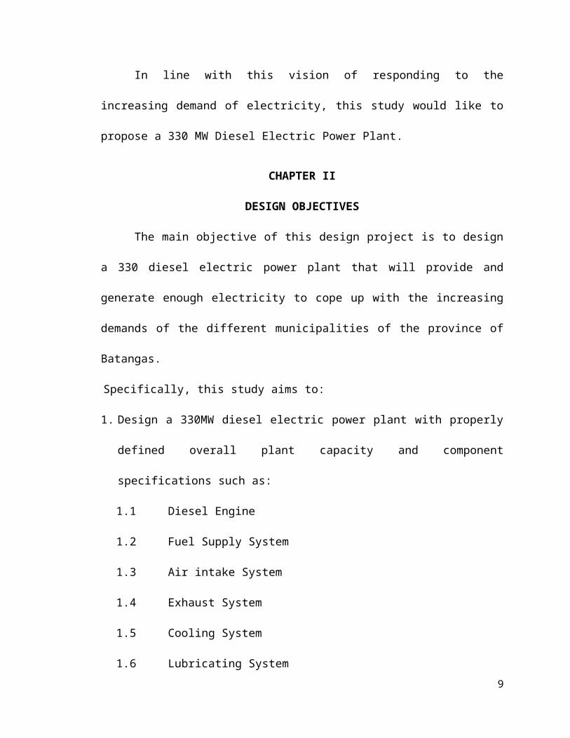
In line with this vision of responding to the increasing demand of
electricity, this study would like to propose a 330 MW Diesel Electric Power
Plant.
6
CHAPTER II
DESIGN OBJECTIVES
The main objective of this design project is to design a 330 diesel electric
power plant that will provide and generate enough electricity to cope up with the
increasing demands of the different municipalities of the province of Batangas.
Specifically, this study aims to:
1. Design a 330MW diesel electric power plant with properly defined overall
plant capacity and component specifications such as:
1.1 Diesel Engine
1.2 Fuel Supply System
1.3 Air intake System
1.4 Exhaust System
1.5 Cooling System
1.6 Lubricating System
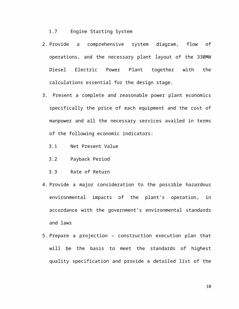
1.7 Engine Starting System
2. Provide a comprehensive system diagram, flow of operations, and the
necessary plant layout of the 330MW Diesel Electric Power Plant together
with the calculations essential for the design stage.
3. Present a complete and reasonable power plant economics specifically the
price of each equipment and the cost of manpower and all the necessary
services availed in terms of the following economic indicators:
3.1 Net Present Value
3.2 Payback Period
7
3.3 Rate of Return
4. Provide a major consideration to the possible hazardous environmental
impacts of the plant’s operation, in accordance with the government’s
environmental standards and laws
5. Prepare a projection – construction execution plan that will be the basis to
meet the standards of highest quality specification and provide a detailed list
of the plants operation from the time of construction to its operation.
8
CHAPTER III
DATA AND ASSUMPTIONS
This chapter presents all the data and information acquired including the
load demand profile of the chosen municipalities and the basic assumptions
which will be used and considered in the design calculation to pursue the
designing process of the 330 MW diesel electric power plant.
Load Demand Profile of the chosen Municipalities
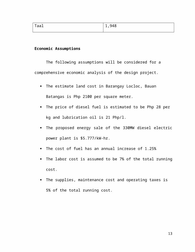
Table 3. Survey of Load Demands of the Proposed Location for 2013
Municipality Load (kW)
Agoncillo 908
Alitagtag 10566.17
Bauan 5,274
Calaca 3,506
Cuenca 21332
Lemery 3,620
Mabini 26241.54
San Luis 976
San Nicolas 540
Sta. Teresita 473
Taal 1,948
Economic Assumptions
9
The following assumptions will be considered for a comprehensive
economic analysis of the design project.
The estimate land cost in Barangay Locloc, Bauan Batangas is Php 2100
per square meter.
The price of diesel fuel is estimated to be Php 28 per kg and lubrication oil
is 21 Php/l.
The proposed energy sale of the 330MW diesel electric power plant is
$5.777/kW-hr.
The cost of fuel has an annual increase of 1.25%
The labor cost is assumed to be 7% of the total running cost.
The supplies, maintenance cost and operating taxes is 5% of the total
running cost.
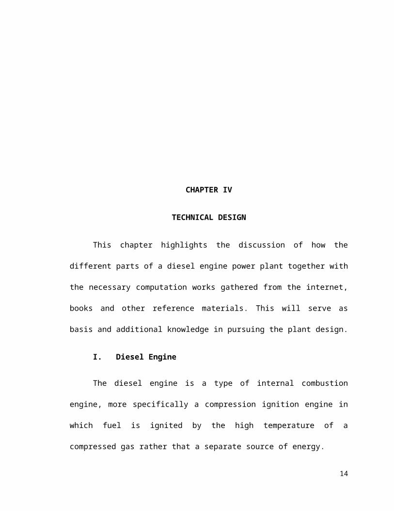
CHAPTER IV
10

TECHNICAL DESIGN
This chapter highlights the discussion of how the different parts of a diesel
engine power plant together with the necessary computation works gathered
from the internet, books and other reference materials. This will serve as basis
and additional knowledge in pursuing the plant design.
I. Diesel Engine
The diesel engine is a type of internal combustion engine, more
specifically a compression ignition engine in which fuel is ignited by the high
temperature of a compressed gas rather that a separate source of energy.
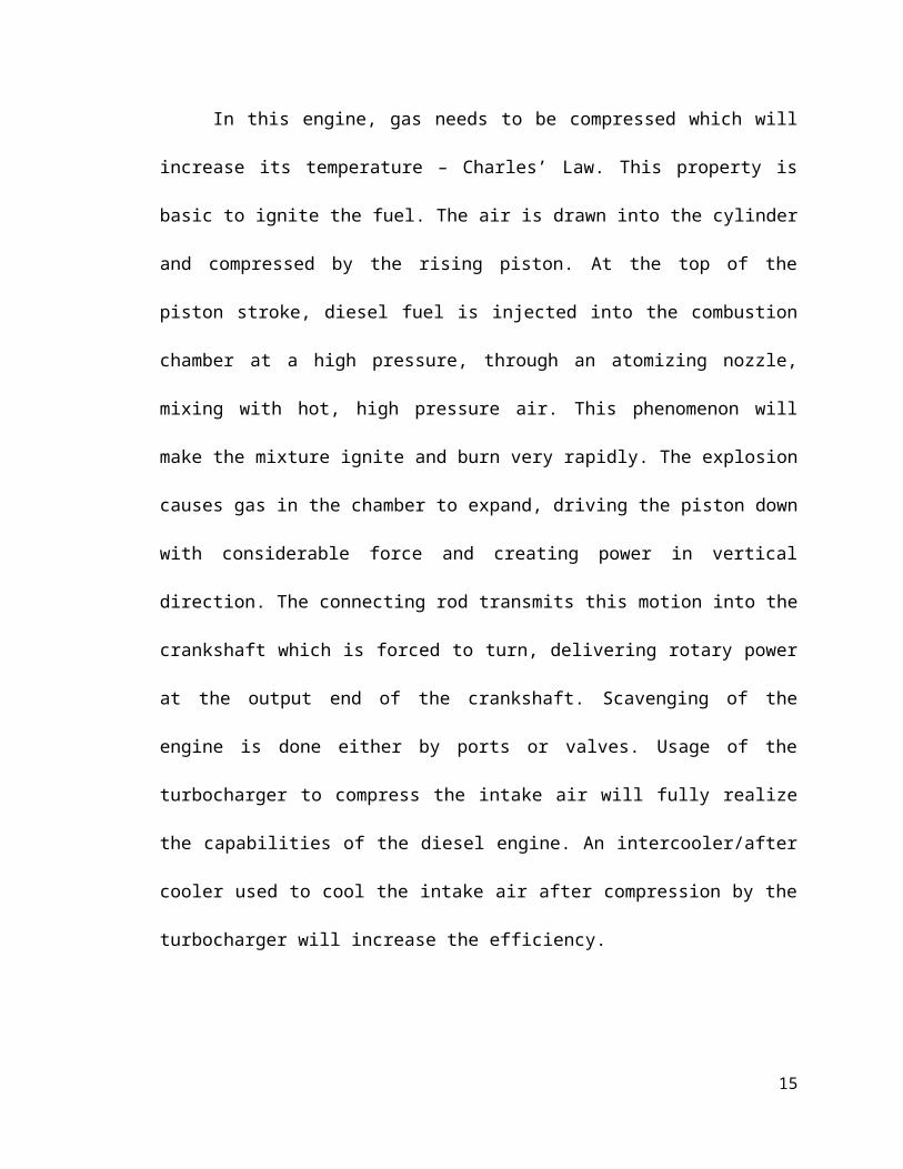
In this engine, gas needs to be compressed which will increase its
temperature – Charles’ Law. This property is basic to ignite the fuel. The air is
drawn into the cylinder and compressed by the rising piston. At the top of the
piston stroke, diesel fuel is injected into the combustion chamber at a high
pressure, through an atomizing nozzle, mixing with hot, high pressure air. This
phenomenon will make the mixture ignite and burn very rapidly. The explosion
causes gas in the chamber to expand, driving the piston down with considerable
force and creating power in vertical direction. The connecting rod transmits this
motion into the crankshaft which is forced to turn, delivering rotary power at the
output end of the crankshaft. Scavenging of the engine is done either by ports or
valves. Usage of the turbocharger to compress the intake air will fully realize the
capabilities of the diesel engine. An intercooler/after cooler used to cool the
intake air after compression by the turbocharger will increase the efficiency.
11
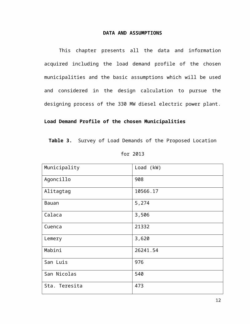
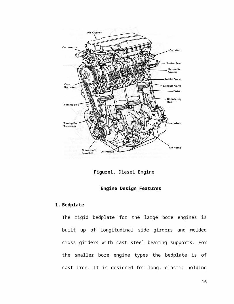
Figure1. Diesel Engine
Engine Design Features
1. Bedplate
The rigid bedplate for the large bore engines is built up of longitudinal
side girders and welded cross girders with cast steel bearing supports.
For the smaller bore engine types the bedplate is of cast iron. It is
designed for long, elastic holding down bolts arranged in a single row
and tightened with hydraulic tools. The main bearings are line with
white metal and the thrust bearing is incorporated in the aft end of the
bedplate. The aftmost cross girder is therefore designed with ample
12
stiffness to transmit the variable thrust from the thrust collar to engine
seating.
2. Frame box
The frame box is equipped on the exhaust side with a relief valve and
on the camshaft side with large door for each cylinder providing access
to the crankshaft components.
3. Cylinder Frame
The cat iron cylinder frames from the top of the frame box make
another significant contribution to the rigidity of the overall engine
structure. The frame include the scavenge boxes which are
dimensioned to ensure that scavenge air is admitted uniformly to the
cylinders. Staybolts are tightened hydraulically to connect the bedplate,
the frame box and the cylinder frames and form a very rigid unit.
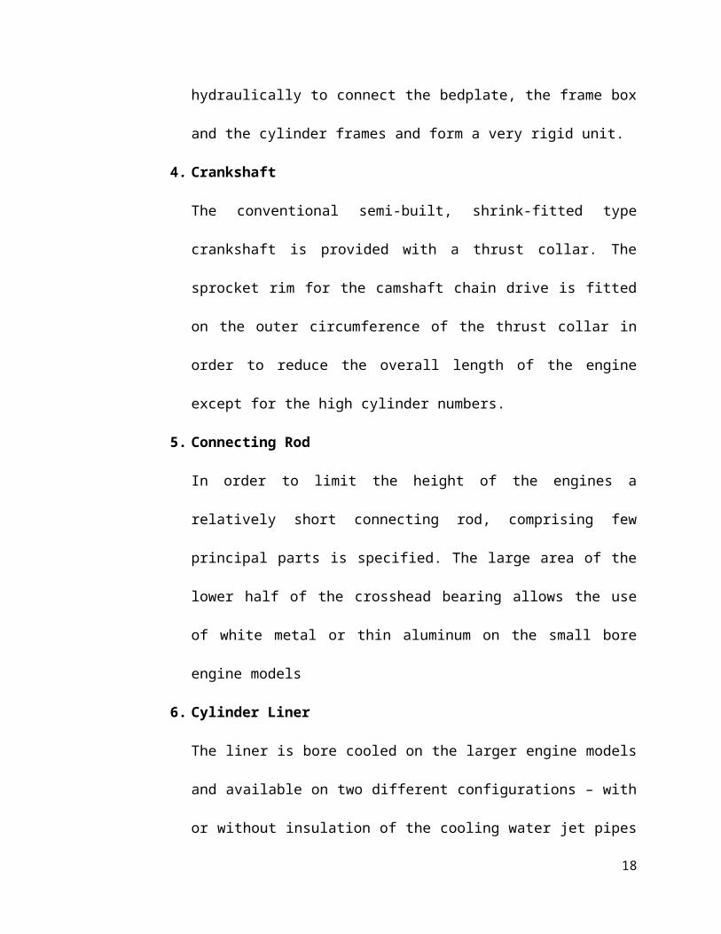
4. Crankshaft
The conventional semi-built, shrink-fitted type crankshaft is provided
with a thrust collar. The sprocket rim for the camshaft chain drive is
fitted on the outer circumference of the thrust collar in order to reduce
the overall length of the engine except for the high cylinder numbers.
5. Connecting Rod
In order to limit the height of the engines a relatively short connecting
rod, comprising few principal parts is specified. The large area of the
lower half of the crosshead bearing allows the use of white metal or
thin aluminum on the small bore engine models
13
6. Cylinder Liner
The liner is bore cooled on the larger engine models and available on
two different configurations – with or without insulation of the cooling
water jet pipes to match the cooling intensity closely to the different
engine ratings.
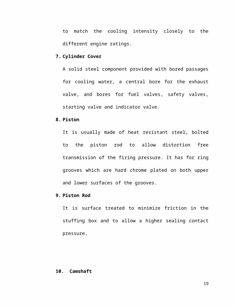
7. Cylinder Cover
A solid steel component provided with bored passages for cooling
water, a central bore for the exhaust valve, and bores for fuel valves,
safety valves, starting valve and indicator valve.
8. Piston
It is usually made of heat resistant steel, bolted to the piston rod to
allow distortion free transmission of the firing pressure. It has for ring
grooves which are hard chrome plated on both upper and lower
surfaces of the grooves.
9. Piston Rod
It is surface treated to minimize friction in the stuffing box and to allow
a higher sealing contact pressure.
10.Camshaft
It drives the fuel injection pumps and the hydraulic exhaust valve
actuator. Cams are shrink fitted to the shaft and can be individually
adjusted by the high pressure oil method.
14
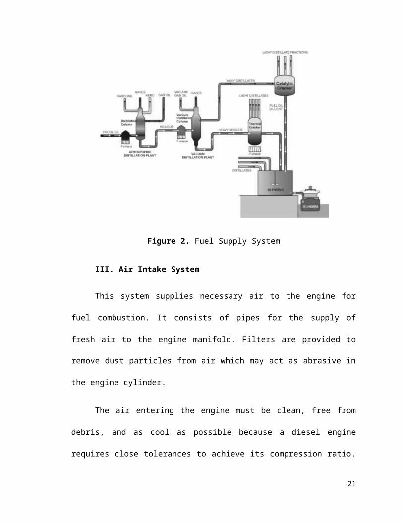
II. Fuel Supply System
It consists of storage tank, strainers, fuel transfer pump and all day fuel
tanks. The fuel oil is supplied at the plant by rail or road. The oil is stored in the
storage tank. From the storage tank, oil is pumped to smaller all day at daily or
short intervals. From this tank, fuel oil is passed through strainers to remove
suspended impurities.
Figure 2. Fuel Supply System
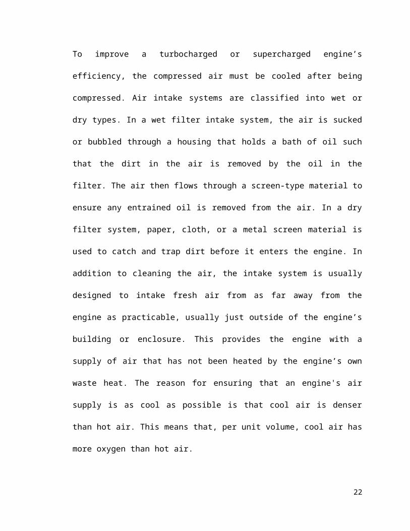
III. Air Intake System
This system supplies necessary air to the engine for fuel combustion. It
consists of pipes for the supply of fresh air to the engine manifold. Filters are
15
provided to remove dust particles from air which may act as abrasive in the
engine cylinder.
The air entering the engine must be clean, free from debris, and as cool
as possible because a diesel engine requires close tolerances to achieve its
compression ratio. To improve a turbocharged or supercharged engine’s
efficiency, the compressed air must be cooled after being compressed. Air intake
systems are classified into wet or dry types. In a wet filter intake system, the air is
sucked or bubbled through a housing that holds a bath of oil such that the dirt in
the air is removed by the oil in the filter. The air then flows through a screen-type
material to ensure any entrained oil is removed from the air. In a dry filter system,
paper, cloth, or a metal screen material is used to catch and trap dirt before it
enters the engine. In addition to cleaning the air, the intake system is usually
designed to intake fresh air from as far away from the engine as practicable,
usually just outside of the engine’s building or enclosure. This provides the
engine with a supply of air that has not been heated by the engine’s own waste
heat. The reason for ensuring that an engine's air supply is as cool as possible is
that cool air is denser than hot air. This means that, per unit volume, cool air has
more oxygen than hot air.
16
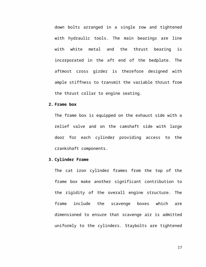
Figure 3. Air Intake System
IV. Exhaust System
This system leads the engine exhaust gas outside the building and
discharges it into the atmosphere. To reduce the noise level of this process; a
silencer is usually incorporated in the system.
The exhaust system of a diesel engine performs three major functions.
First, the exhaust system routes the spent combustion gases away from the
engine, where they are diluted by the atmosphere. This keeps the area around
the engine habitable. Second, the exhaust system confines and routes the gases
to the turbocharger if used. Lastly, the exhaust system allows mufflers to be used
to reduce the engine noise.
17
V. Cooling System
The heat released by the burning of fuel in the engine cylinder is partially
converted into work. The remaining amount of heat passes through the cylinder
wall, piston, rings and other parts may cause damage to the system. Cooling is
provided in order to keep the temperature of the engine parts within safe
operating limits. It consists of a water source, pump and cooling towers. The
pump circulates water through cylinder and head jacket. The water takes away
heat from the engine and becomes hot. The hot water is cooled by cooling
towers and then re-circulated for cooling.
Figure 4. Cooling Water System
18
VI. Lubricating System
This system minimizes the wear of rubbing surfaces of the engine. It
comprises of lubricating oil tank, pump, filter and oil cooler. The lubrication oil is
drawn from the lubricating oil tank by the pump and is passed through filter to
remove impurities .The clean lubrication oil is delivered to the points which
require lubrication. The oil coolers incorporated in the system keep the
temperature of the oil low.
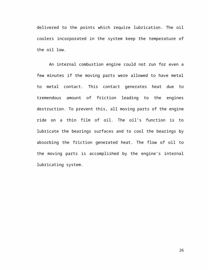
An internal combustion engine could not run for even a few minutes if the
moving parts were allowed to have metal to metal contact. This contact
generates heat due to tremendous amount of friction leading to the engines
destruction. To prevent this, all moving parts of the engine ride on a thin film of
oil. The oil’s function is to lubricate the bearings surfaces and to cool the
bearings by absorbing the friction generated heat. The flow of oil to the moving
parts is accomplished by the engine’s internal lubricating system.
19
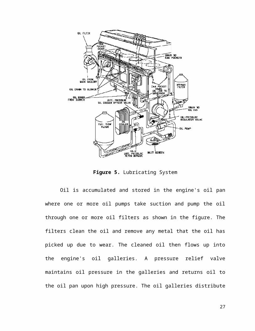
Figure 5. Lubricating System
Oil is accumulated and stored in the engine's oil pan where one or more
oil pumps take suction and pump the oil through one or more oil filters as shown
in the figure. The filters clean the oil and remove any metal that the oil has picked
up due to wear. The cleaned oil then flows up into the engine's oil galleries. A
pressure relief valve maintains oil pressure in the galleries and returns oil to the
oil pan upon high pressure. The oil galleries distribute the oil to all the bearing
surfaces in the engine. Once the oil has cooled and lubricated the bearing
surfaces, it flows out of the bearing and gravity-flows back into the oil pan. In
medium to large diesel engines, the oil is also cooled before being distributed
20
into the block. This is accomplished by either internal or external oil cooler. The
lubrication system also supplies oil to the engine’s governor.
VII. Engine Starting System
This is an arrangement to rotate the engine initially, while starting, until
firing starts and the unit runs with its own power. Usually, small sets are started
manually by handling but larger units use compressed air for starting.
Starting Circuits
Diesel engines have as many different types of starting circuits as
there are types, sizes, and manufacturers of diesel engines. Commonly,
they can be started by air motors, electric motors, hydraulic motors, and
manually. The start circuit is usually a simple start pushbutton or a
complex auto-start circuit. The following process must occur to start the
engine.
a. The start signal is sent to the starting motor. The air electric or
hydraulic motor will engage the engine’s flywheel.
b. The starting motor will crank the engine. It will let the engine
reach a high enough rpm to allow the engine’s compression to
ignite the fuel and start the engine running.
c. The engine will then accelerate to idle speed. When the starter
motor is overdriven by the running motor it will disengage the
flywheel.
21
22
23
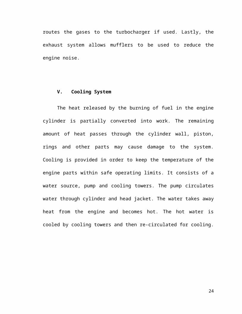
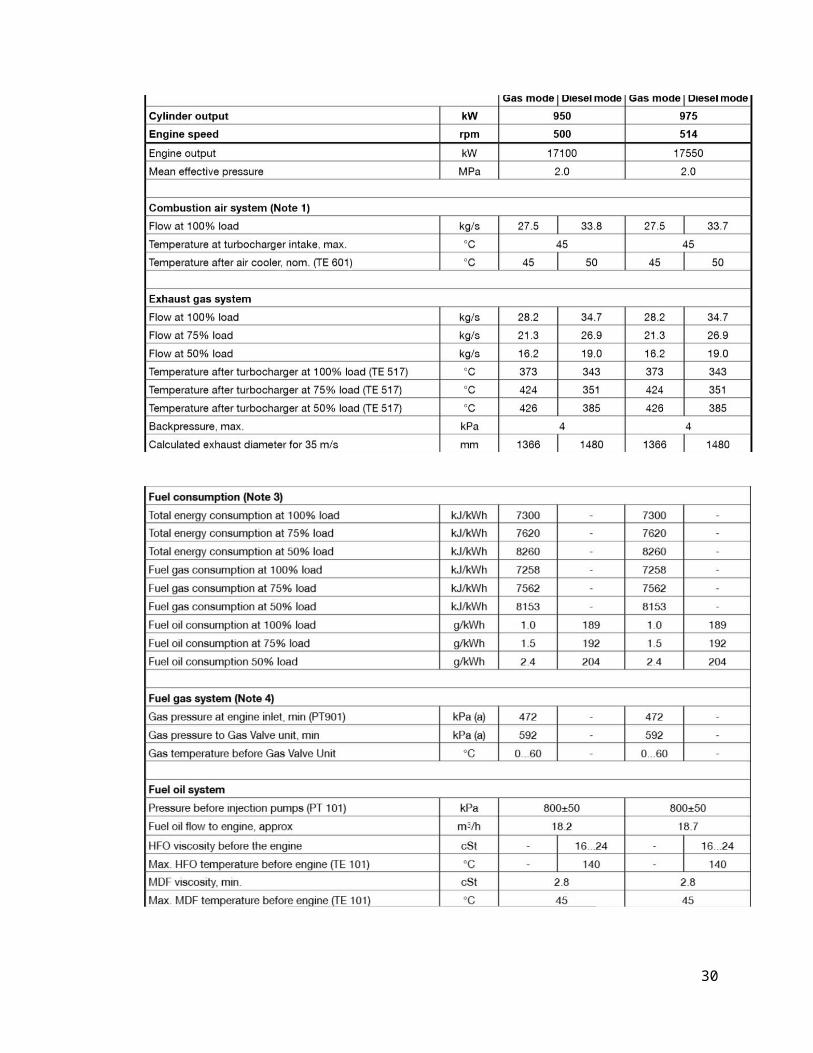
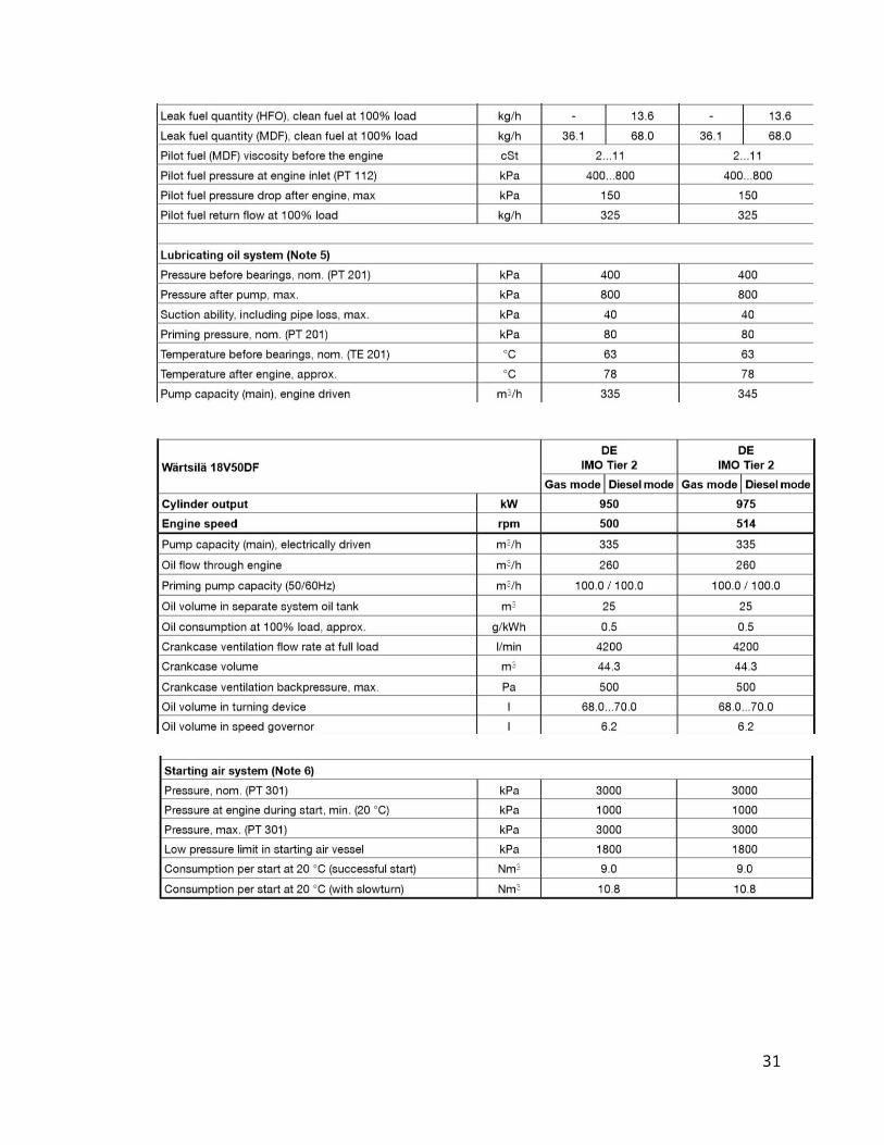
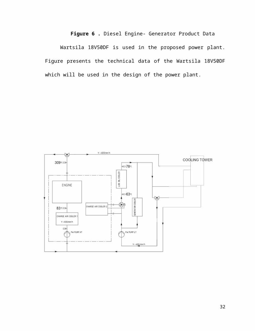
Figure 6 . Diesel Engine- Generator Product Data
Wartsila 18V50DF is used in the proposed power plant. Figure presents
the technical data of the Wartsila 18V50DF which will be used in the design of
the power plant.
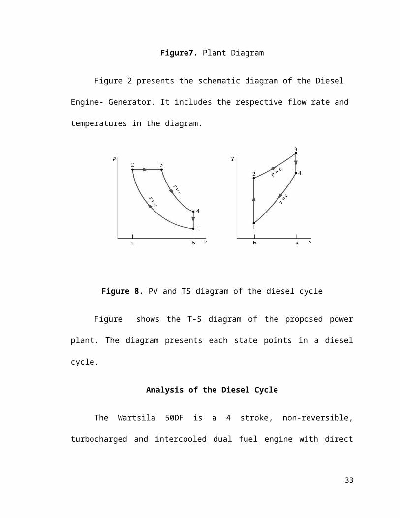
Figure7. Plant Diagram
Figure 2 presents the schematic diagram of the Diesel Engine- Generator.
It includes the respective flow rate and temperatures in the diagram.
24
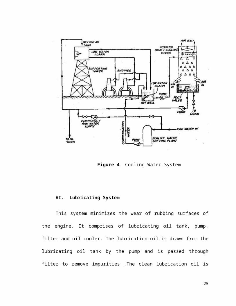
Figure 8. PV and TS diagram of the diesel cycle
Figure shows the T-S diagram of the proposed power plant. The diagram
presents each state points in a diesel cycle.
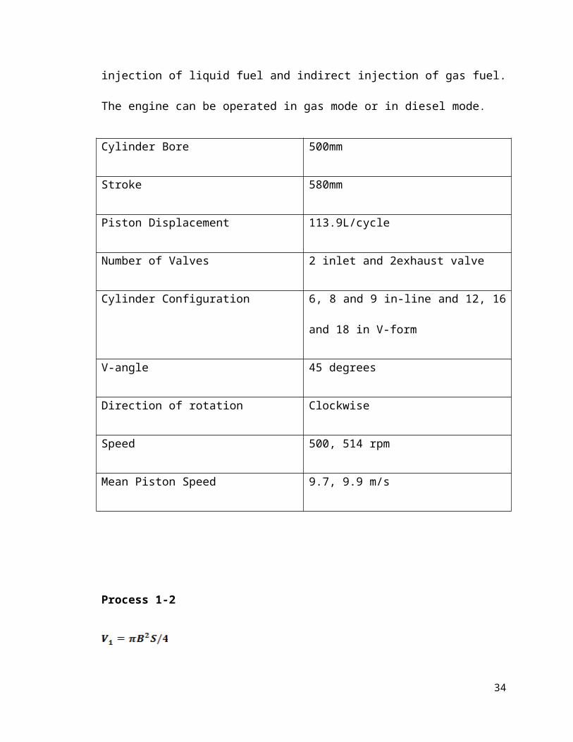
Analysis of the Diesel Cycle
The Wartsila 50DF is a 4 stroke, non-reversible, turbocharged and
intercooled dual fuel engine with direct injection of liquid fuel and indirect injection
of gas fuel. The engine can be operated in gas mode or in diesel mode.
Cylinder Bore 500mm
Stroke 580mm
Piston Displacement 113.9L/cycle
Number of Valves 2 inlet and 2exhaust valve
Cylinder Configuration 6, 8 and 9 in-line and 12, 16 and 18 in
V-form
25
V-angle 45 degrees
Direction of rotation Clockwise
Speed 500, 514 rpm
Mean Piston Speed 9.7, 9.9 m/s
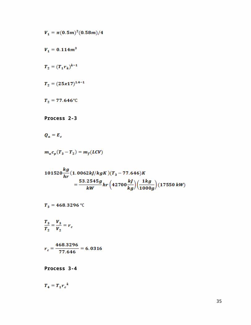
Process 1-2
Process 2-3
26
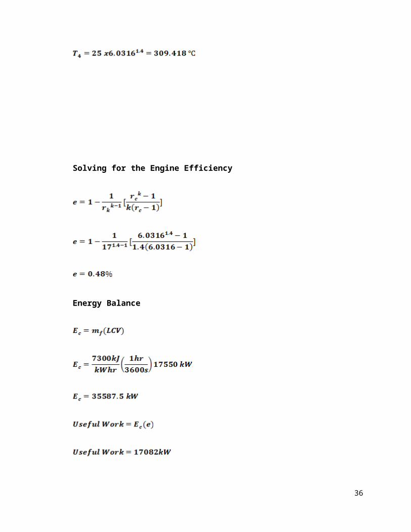
Process 3-4
Solving for the Engine Efficiency
27
Energy Balance
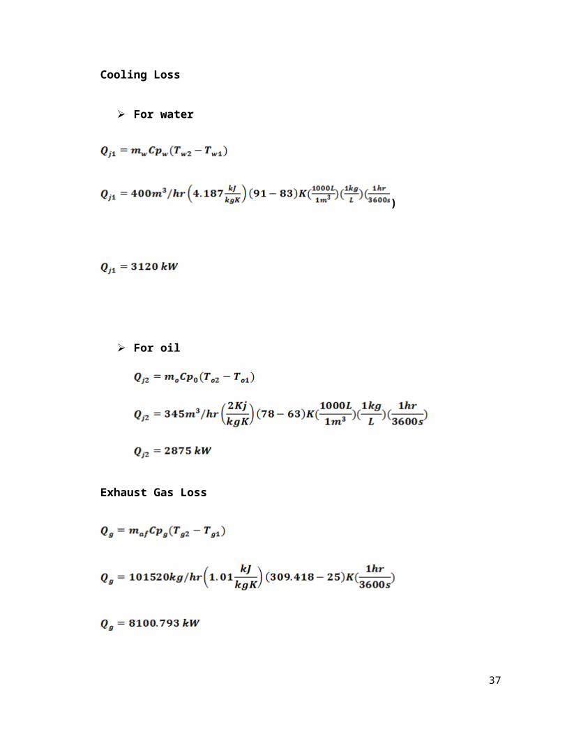
Cooling Loss
For water
)
For oil
28
Exhaust Gas Loss
29
Generator
KWe= Generator Efficiency x Ec
= 0.965 x 0.48 x 35587.5 kW
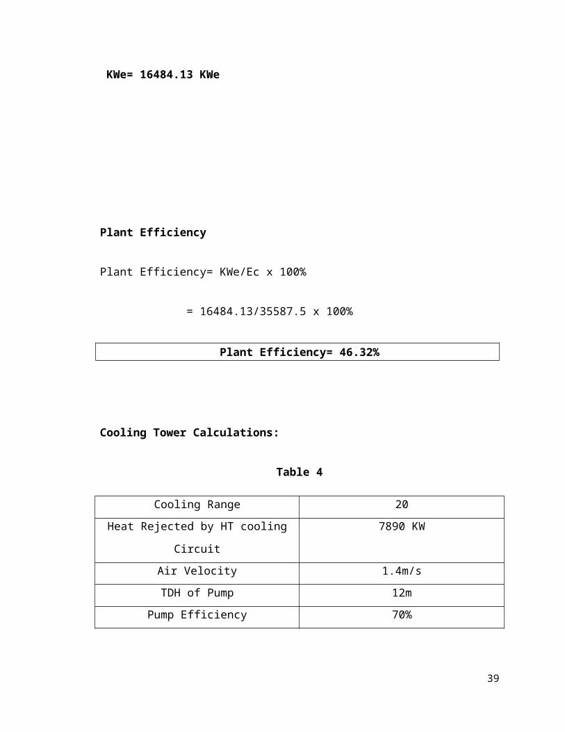
KWe= 16484.13 KWe
Plant Efficiency
Plant Efficiency= KWe/Ec x 100%
= 16484.13/35587.5 x 100%
Plant Efficiency= 46.32%
Cooling Tower Calculations:
Table 4
Cooling Range 20
Heat Rejected by HT cooling Circuit 7890 KW
Air Velocity 1.4m/s
30
TDH of Pump 12m
Pump Efficiency 70%
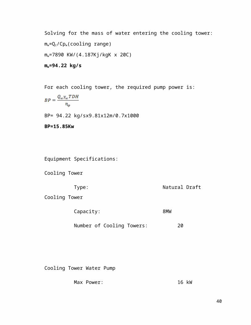
Solving for the mass of water entering the cooling tower:
mw=Qr/Cpw(cooling range)
mw=7890 KW/(4.187Kj/kgK x 20C)
mw=94.22 kg/s
For each cooling tower, the required pump power is:
BP= 94.22 kg/sx9.81x12m/0.7x1000
BP=15.85Kw
Equipment Specifications:
Cooling Tower
Type: Natural Draft Cooling Tower
Capacity: 8MW
Number of Cooling Towers: 20
Cooling Tower Water Pump
Max Power: 16 kW
Speed: up to 1000 rpm
31
Max Head: up to 12m
CHAPTER V
ECONOMIC ANALYSIS
This chapter presents the power plant economics of the designed 330 MW
Diesel Electric Power Plant.
Plant Economics
A power station’s function is to deliver power at the lowest possible cost
per kilo watt hour. The charges must include the of interest on the capital, taxes,
insurance, depreciation and salary of managerial staff, the operating expenses
such as cost of fuels, water, oil, labor, repairs and maintenance.
The power production can be minimized by:
32
1. Reducing the amount of investment in the plant.
2. The plant must be operated by fewer worker
3. The plant must be uniformly designed
4. Selecting the station as to reduce cost of fuel, labor, etc.
All the electrical energy generated in a power station must be consumed
immediately as it cannot be stored. So the electrical energy generated in a power
station must be regulated according to the demand. The demand of electrical
energy or load will also vary with the time and a power station must be capable of
meeting the maximum load at any time.
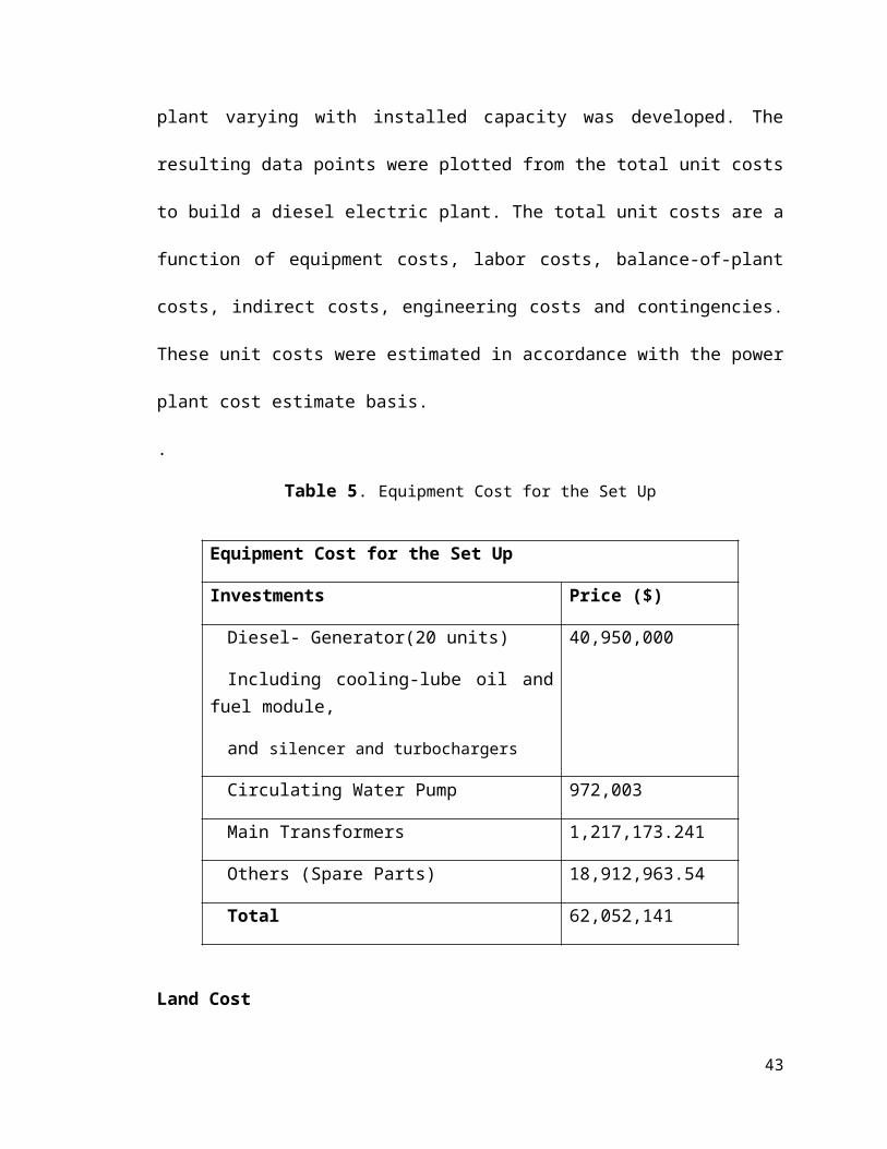
In order to predict power plant costs given the desired output power, a
model to relate the unit cost of a new power plant varying with installed capacity
was developed. The resulting data points were plotted from the total unit costs to
build a diesel electric plant. The total unit costs are a function of equipment costs,
labor costs, balance-of-plant costs, indirect costs, engineering costs and
contingencies. These unit costs were estimated in accordance with the power
plant cost estimate basis.
.
Table 5. Equipment Cost for the Set Up
Equipment Cost for the Set Up
Investments Price ($)
Diesel- Generator(20 units)
Including cooling-lube oil and fuel module,
and silencer and turbochargers
40,950,000
33
Circulating Water Pump 972,003
Main Transformers 1,217,173.241
Others (Spare Parts) 18,912,963.54
Total 62,052,141
Land Cost
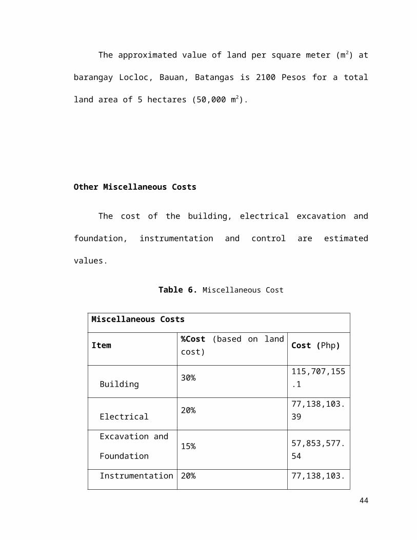
The approximated value of land per square meter (m2) at barangay
Locloc, Bauan, Batangas is 2100 Pesos for a total land area of 5 hectares
(50,000 m2).
Other Miscellaneous Costs
The cost of the building, electrical excavation and foundation,
instrumentation and control are estimated values.
Table 6. Miscellaneous Cost
Miscellaneous Costs
Item %Cost (based on land cost) Cost (Php)
Building 30% 115,707,155.1
Electrical 20% 77,138,103.39
Excavation and
Foundation 15%
57,853,577.54
34
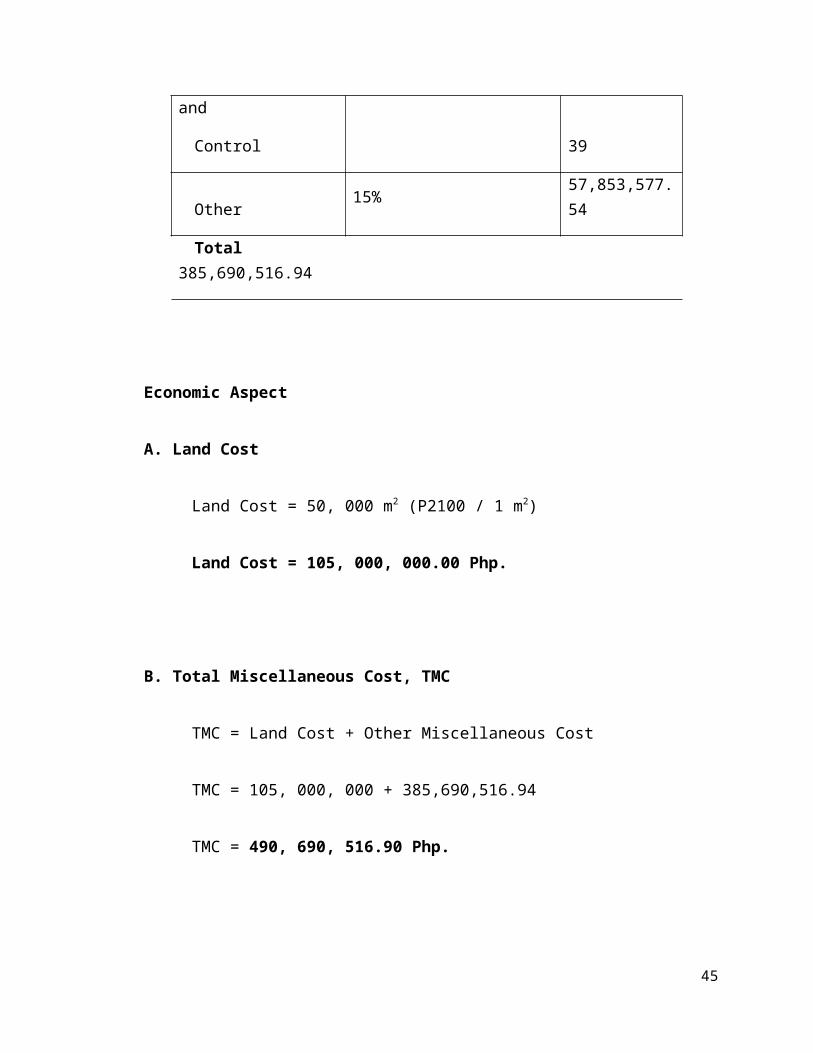
Instrumentation and
Control20%
77,138,103.39
Other 15% 57,853,577.54
Total 385,690,516.94
Economic Aspect
A. Land Cost
Land Cost = 50, 000 m2 (P2100 / 1 m2)
Land Cost = 105, 000, 000.00 Php.
B. Total Miscellaneous Cost, TMC
TMC = Land Cost + Other Miscellaneous Cost
TMC = 105, 000, 000 + 385,690,516.94
TMC = 490, 690, 516.90 Php.
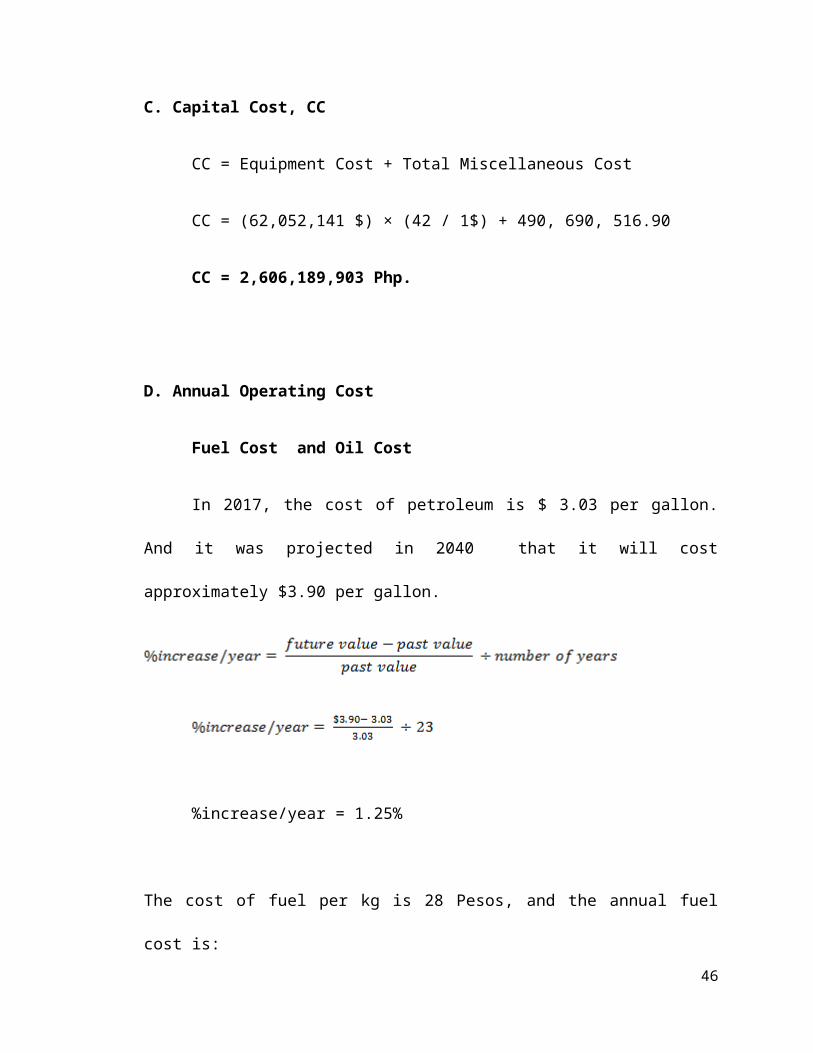
C. Capital Cost, CC
CC = Equipment Cost + Total Miscellaneous Cost
CC = (62,052,141 $) × (42 / 1$) + 490, 690, 516.90
35
CC = 2,606,189,903 Php.
D. Annual Operating Cost
Fuel Cost and Oil Cost
In 2017, the cost of petroleum is $ 3.03 per gallon. And it was projected in
2040 that it will cost approximately $3.90 per gallon.
%increase/year = 1.25%
The cost of fuel per kg is 28 Pesos, and the annual fuel cost is:
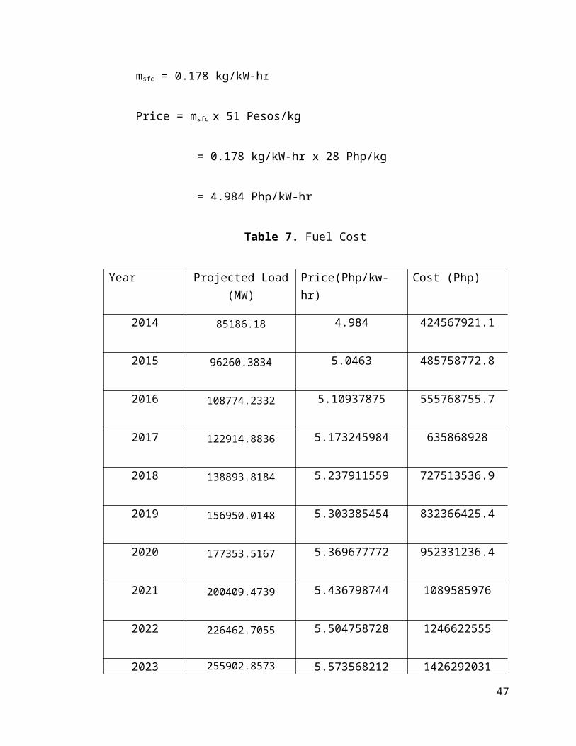
msfc = 0.178 kg/kW-hr
Price = msfc x 51 Pesos/kg
= 0.178 kg/kW-hr x 28 Php/kg
= 4.984 Php/kW-hr
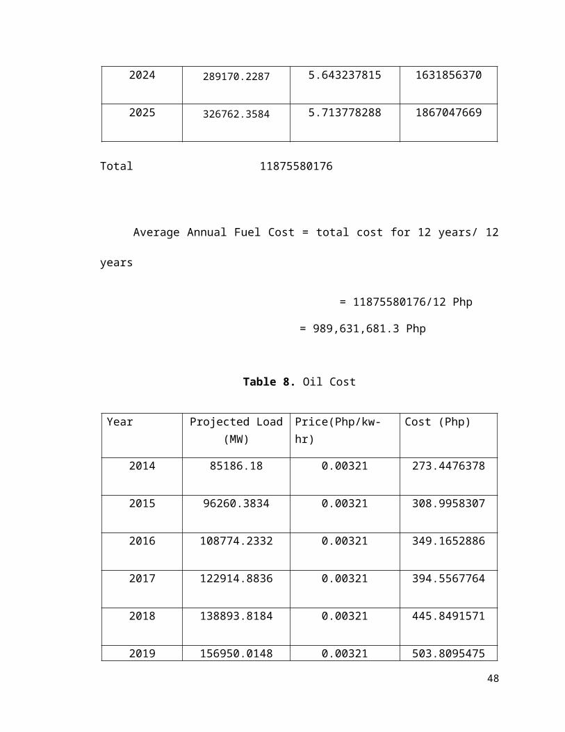
Table 7. Fuel Cost
Year Projected Load (MW)
Price(Php/kw-hr) Cost (Php)
36
2014 85186.18 4.984 424567921.1
2015 96260.3834 5.0463 485758772.8
2016 108774.2332 5.10937875 555768755.7
2017 122914.8836 5.173245984 635868928
2018 138893.8184 5.237911559 727513536.9
2019 156950.0148 5.303385454 832366425.4
2020 177353.5167 5.369677772 952331236.4
2021 200409.4739 5.436798744 1089585976
2022 226462.7055 5.504758728 1246622555
2023 255902.8573 5.573568212 1426292031
2024 289170.2287 5.643237815 1631856370
2025 326762.3584 5.713778288 1867047669
Total 11875580176
Average Annual Fuel Cost = total cost for 12 years/ 12 years
= 11875580176/12 Php
= 989,631,681.3 Php
37
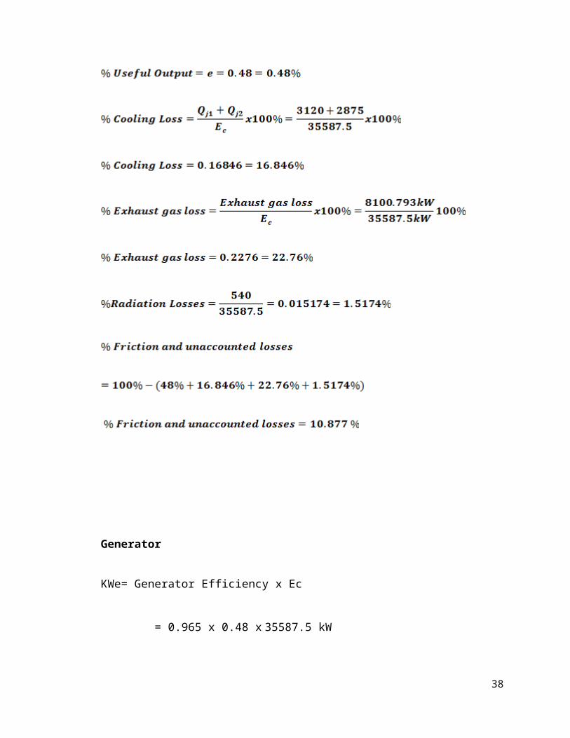
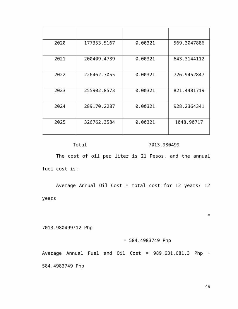
Table 8. Oil Cost
Year Projected Load (MW)
Price(Php/kw-hr) Cost (Php)
2014 85186.18 0.00321 273.4476378
2015 96260.3834 0.00321 308.9958307
2016 108774.2332 0.00321 349.1652886
2017 122914.8836 0.00321 394.5567764
2018 138893.8184 0.00321 445.8491571
2019 156950.0148 0.00321 503.8095475
2020 177353.5167 0.00321 569.3047886
2021 200409.4739 0.00321 643.3144112
2022 226462.7055 0.00321 726.9452847
2023 255902.8573 0.00321 821.4481719
2024 289170.2287 0.00321 928.2364341
2025 326762.3584 0.00321 1048.90717
Total 7013.980499
The cost of oil per liter is 21 Pesos, and the annual fuel cost is:
Average Annual Oil Cost = total cost for 12 years/ 12 years
38
= 7013.980499/12 Php
= 584.4983749 Php
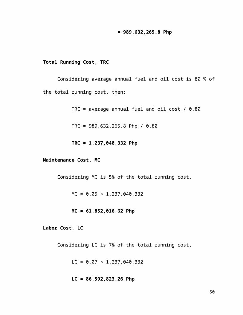
Average Annual Fuel and Oil Cost = 989,631,681.3 Php + 584.4983749 Php
= 989,632,265.8 Php
Total Running Cost, TRC
Considering average annual fuel and oil cost is 80 % of the total running
cost, then:
TRC = average annual fuel and oil cost / 0.80
TRC = 989,632,265.8 Php / 0.80
TRC = 1,237,040,332 Php
Maintenance Cost, MC
Considering MC is 5% of the total running cost,
MC = 0.05 × 1,237,040,332
MC = 61,852,016.62 Php
Labor Cost, LC
Considering LC is 7% of the total running cost,
LC = 0.07 × 1,237,040,332
LC = 86,592,823.26 Php
39
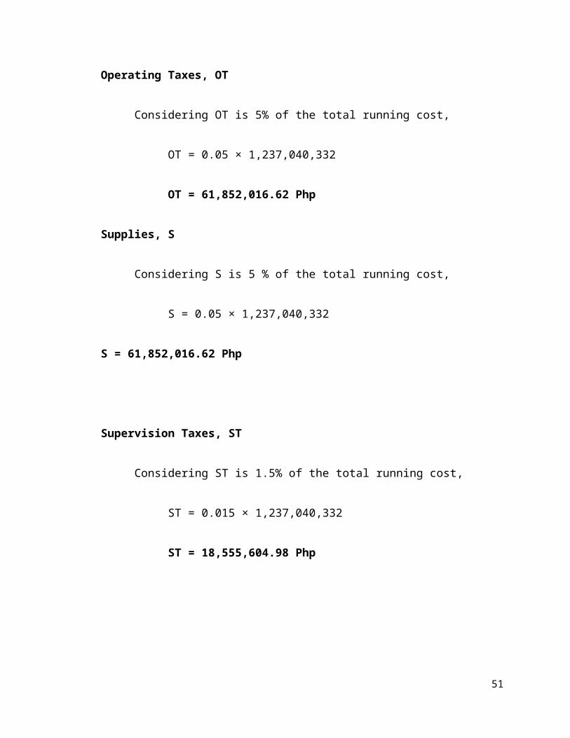
Operating Taxes, OT
Considering OT is 5% of the total running cost,
OT = 0.05 × 1,237,040,332
OT = 61,852,016.62 Php
Supplies, S
Considering S is 5 % of the total running cost,
S = 0.05 × 1,237,040,332
S = 61,852,016.62 Php
Supervision Taxes, ST
Considering ST is 1.5% of the total running cost,
ST = 0.015 × 1,237,040,332
ST = 18,555,604.98 Php
40
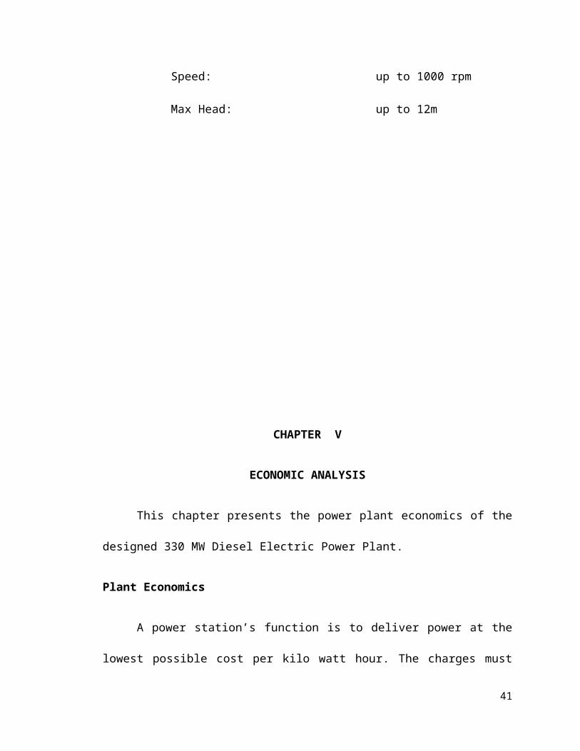
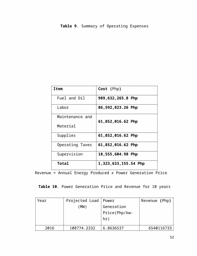
Table 9. Summary of Operating Expenses
Revenue = Annual Energy Produced x Power Generation Price
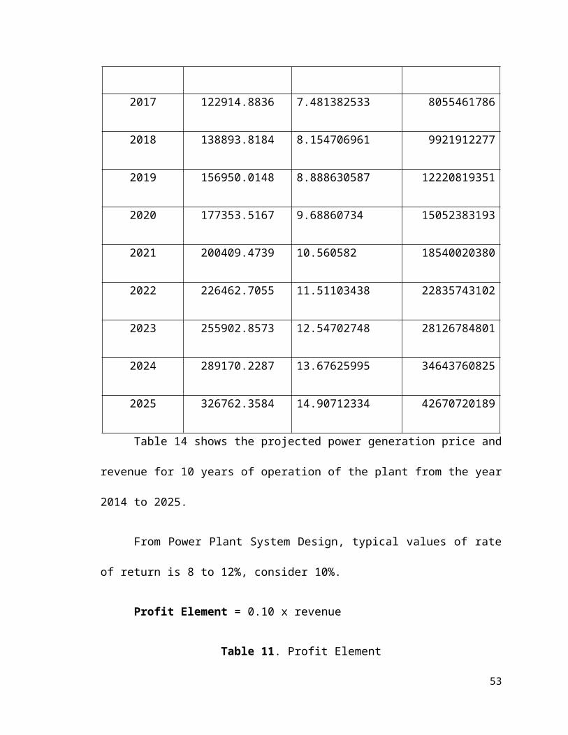
Table 10. Power Generation Price and Revenue for 10 years
Year Projected Load (MW)
Power Generation Price(Php/kw-hr)
Revenue (Php)
2016 108774.2332 6.8636537 6540116733
2017 122914.8836 7.481382533 8055461786
2018 138893.8184 8.154706961 9921912277
41
Item Cost (Php)
Fuel and Oil 989,632,265.8 Php
Labor 86,592,823.26 Php
Maintenance and
Material61,852,016.62 Php
Supplies 61,852,016.62 Php
Operating Taxes 61,852,016.62 Php
Supervision 18,555,604.98 Php
Total 1,323,633,155.54 Php
2019 156950.0148 8.888630587 12220819351
2020 177353.5167 9.68860734 15052383193
2021 200409.4739 10.560582 18540020380
2022 226462.7055 11.51103438 22835743102
2023 255902.8573 12.54702748 28126784801
2024 289170.2287 13.67625995 34643760825
2025 326762.3584 14.90712334 42670720189
Table 14 shows the projected power generation price and revenue for 10
years of operation of the plant from the year 2014 to 2025.
From Power Plant System Design, typical values of rate of return is 8 to
12%, consider 10%.
Profit Element = 0.10 x revenue
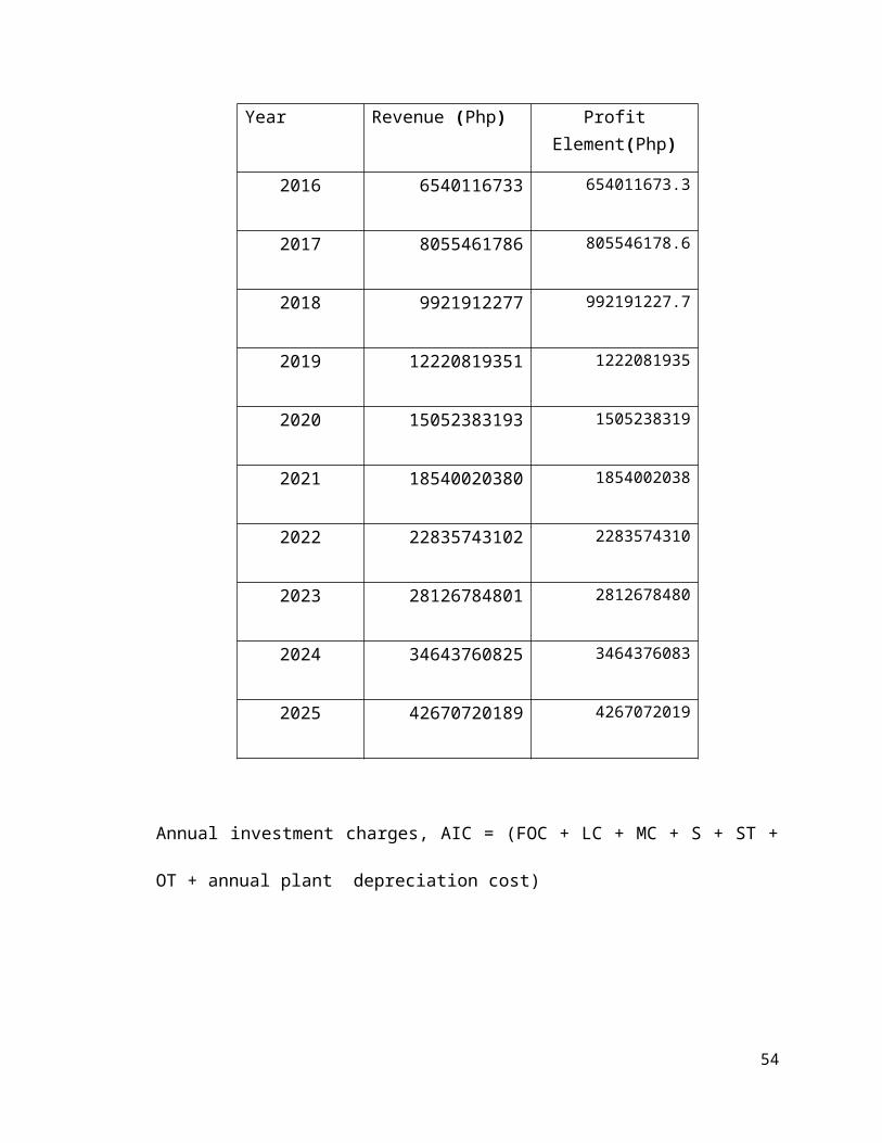
Table 11. Profit Element
Year Revenue (Php) Profit Element(Php)
2016 6540116733 654011673.3
2017 8055461786 805546178.6
2018 9921912277 992191227.7
42
2019 12220819351 1222081935
2020 15052383193 1505238319
2021 18540020380 1854002038
2022 22835743102 2283574310
2023 28126784801 2812678480
2024 34643760825 3464376083
2025 42670720189 4267072019
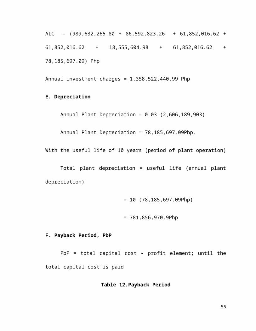
Annual investment charges, AIC = (FOC + LC + MC + S + ST + OT + annual
plant depreciation cost)
AIC = (989,632,265.80 + 86,592,823.26 + 61,852,016.62 + 61,852,016.62 +
18,555,604.98 + 61,852,016.62 + 78,185,697.09) Php
Annual investment charges = 1,358,522,440.99 Php
E. Depreciation
Annual Plant Depreciation = 0.03 (2,606,189,903)
Annual Plant Depreciation = 78,185,697.09Php.
With the useful life of 10 years (period of plant operation)
Total plant depreciation = useful life (annual plant depreciation)
43
= 10 (78,185,697.09Php)
= 781,856,970.9Php
F. Payback Period, PbP
PbP = total capital cost - profit element; until the total capital cost is paid
Table 12.Payback Period
Year Total capital cost(Php) Profit Element(Php)
2014 2,606,189,903 431097612.2 2,175,092,291
2015 2,175,092,291 530982928.9 1,644,109,362
2016 1,644,109,362 654011673.3 990,097,689
2017 990,097,689 805546178.6 184,551,510
2018 184,551,510 992191227.7 -807,639,718
Payback Period = 5 years
Approximately five (5) years is the expected payback period of the plant.
CHAPTER VI
ENVIRONMENTAL MANAGEMENT
44
This chapter incorporates the environmental standards for the design
policies related to the Diesel Electric Power Plant.
Environmental Aspect
Environmental Management Plan
Environmental conditions shall provide dust control of all excavations,
material sites, roads, disposal areas within its assigned areas of responsibility
and shall provide suitable equipment, facilities and precautions limit, the
discharge of contaminants and noise level. The ambient air quality impact
resulting from the emission of pollutants shall not exceed the National Ambient
Air Quality Standards for Source Specific Air Pollutants. Noise generated during
power plant operation shall conform to Noise Standards stipulated in NPCC
memorandum. The waste water discharges from the power plant complex shall
not cause the water quality of bodies around the power plant to exceed the
standards set by DENR.
One of the important first steps in establishing an environmental
management system is to understand the range and diversity of environmental
issues to be addressed.
The list of issues is no longer than many managers at first believe. The
relationship between issues is also an important factor, for action on one issue
can easily affect the estate’s performance on another.
45
The preparation of a comprehensive environmental assessment report is
thus an important first step.
Some of the specific management elements, which contribute to improving
environmental performance, are described below.
Elements of an Environmental Program
1. Sound policies and clear objectives, which define environmental issues and
identify the state’s approach, such as emphasis on prevention rather than
treatment.
2. Well-defined operating standards and realistic targets for discharges and site
safety.
3. Visible and effective management commitment to environmental protection.
4. Clearly defined line management responsibility and accountability.
5. Adequate resources for the program.
6. Regular review of environmental performance e.g. audits.
7. Programs on training and awareness on environmental risks.
8. Effective incident reporting and investigation.
9. Effective contingency planning for accidents, spills and fires.
10. Reporting systems within the estate, and with the public.
Environmental Monitoring
46
Stack and ambient air quality monitoring devices and testing facilities shall
be provided for proper determination of the nature and quantity of air pollutants
which are or may emitted as a result of power plant operation. All testing
procedure shall be acceptable to DENR.
Water quality monitoring equipment and testing facilities shall be provided
to test compliance of the power plant to DENR.
The handling and storage of solid waste and hazardous waste from the
power station facilities shall be in accordance with the DENR Administrative
Order.
A pollution control officer should be appointed during construction whose
duties and responsibilities should be in accordance with DENR.
Replacement of the landfill refuse will require a properly engineered
disposal facility to before re-location of the dump facility.
Before the refuse can be removed from its present site, a new site should
be found, with adequate storage capacity.
The landfill site should be properly engineered, to prevent leaching of
trace metals, heavy metals, particulate organic matter (POM) and dissolved
organic matter (DOM)/nutrients.
Of course if the above is not done, then there will be inevitable pollution of
soils, surface and groundwater and eventually coastal water. This will create
health and safety hazards.
47
Power plants should comply with the following laws:
(According to the news release of EMB-DENR dated October 9, 2002 and the
power plants managers themselves said so.)
• Philippine Environmental Impact Statement System,
• The Philippine Clean Air Act,
• DENR Effluent Regulations,
• Toxic and Hazardous Waste Act of 1990,
• Ecological Solid Waste Management Act and other permit requirements
The management shall adopt and implement programs for environmental
protection and occupational health and safety during construction and
operations. They shall have a waste management plan and shall be responsible
for the safe handling and disposal of hazardous or toxic waste.
CHAPTER VII
PROJECTION CONSTRUCTION EXECUTION PLAN
This chapter addresses the planning problem of a 330 MW Diesel Electric
Power Plant by optimal allocation of diesel fuel portfolios in long term fixed
contracts and short term market. It includes the method of the design policies
related to the project management of the entire operation of the plant.
48
I. Construction Strategy and Management
The construction of buildings and engine layout are similar in many
respects to the steam power plants, although on a much smaller scale. A steel
frame with brick panels and asbestos sheet roof is quite satisfactory. Good
natural lighting can be provided by including large vertical or horizontal windows
in the side walls and rows of skylights in the engine house roof. Quick deliveries,
simplicity of operation and ability to start quickly are in the favor of diesel plants.
However, the direct numerical comparison is meaningless unless
accompanied by a detailed analysis of each plant in respect to the construction
difficulties encountered during erection, special foundation needs equipment,
transportation costs, availability of materials and labor and other differences
caused by location and general financial conditions.
Diesel plants can be located very near to the load centers, many times in the
heart of the town. The diesel plants are admirably suited to load centre location.
The combination of fuel economy, remote operational control, flexibility as to
installed capacity and high degree of freedom from hazard allow placement of
diesel generation sets almost anywhere that it would be useful and economical.
Management Strategies
Control measures will minimize the likelihood of accidents at the power
station or due to transportation of hazardous materials. When a detailed design
of the power station is completed, a Risk Management and Emergency
49
Response Plan will be developed prior to commissioning for review by
appropriate stakeholders. The plan will cover:
•Design specifications for layout, selection of materials, construction and
operation of the facility preventative measures;
• Specific details of natural gas handling, metering and management
procedures;
• control measures;
• Non-technical measures including organizational and systems measures;
• Safety training;
• Emergency plans (on-site and off-site);
• monitoring;
• Incident and safety reporting; and
• Community consultation and information.
These risk management approaches will follow the National Standard for
the Control of Major Hazard Facilities developed by the National Occupational
Health and Safety Commission.
II. Quality Control
The basic activities of quality assurance are: prevention, verification and
correction. This yields the process flows necessary for a specific customer order.
50
Quality Assurance
Project quality assurance program activities include:
• Planning for project quality.
• Specifications for project quality assurance.
• Auditing system for Quality Assurance (QA).
• Selection for supplier and contractor.
• Manufacturing Code Review
• QA procedures and regulations for establishment of works and site.
• Program monitoring.
• General and technical testing and inspection for the materials,
equipments, and safety of the workers.
• Payment verification of the plant and management progress.
III. Risk Management
The main risk refers to fire. Individual injury risk is estimated at less than
one in a million per year based on the risk of pipeline failure, the probability of
gas dispersion to near a residence and the flash fire radius and intensity. Heat
radiation from a tank and bund fire would not extend to the distance of a
residence.
51
The air emission modeling for a major tank and bund fire suggests that
individual risk of injury from smoke inhalation would depend on the potential risk
of fire (eg. 10 in a million per year) and the dispersion of smoke. The individual
risk of smoke inhalation could be less than one in a million per year. The risk of
injury depends on major bund fire frequency and the probability of exposure to
toxic smoke under prevailing climatic conditions.
Public risk is expected to be low because of the low probability of initiating
events and the proposed control measures. The impact of adverse incidents is
also reduced due to the type of land use and low-level density of residents within
a radius of approximately 2 kilometers. Three residences occur close to or about
1 kilometer from the proposed site.
Risk Assessment Process
• Review of previous reports
• Review of power plant information
• Engineering documents review
• Location visit to learn specifics of operations
• Identify and quantify hazards
• Create risk assessment report
IV. Work Scheduling
52
Getting the plant built under schedule and budget is one thing, but the
plant operating staff had to confront some additional challenges. A new diesel
electric power plant had to be up and running on an aggressive time schedule.
CHAPTER VIII
SUMMARY OF FINDINGS, CONCLUSION AND RECOMMENDATIONS
Summary of Results and Discussion
53
The Project Company proposes to develop a diesel electric power plant of
total capacity 330 MW at the coastal area of Locloc, Bauan, Batangas . The site
is an Industrial Setting and does not contain significant residual environmental
sensitivity of importance. Using diesel fuel to generate electricity, particularly in
higher efficiency diesel electric power systems, can reduce the environmental
impact of energy usage in this country.
In general, high load factors and large differences in the prices of diesel
and boiler fuel will tend to lower the value of installed capacity. Quick deliveries,
simplicity of operation and ability to start quickly are in the favor of diesel plants.
The key environmental issues associated with the power plant are as follows:
• Emission of carbon dioxide to the air;
• Generation and disposal of liquid effluents including cooling water;
and
• Emission of noise.
The potential impacts of the carbon dioxide emissions to the air,
generation and disposal of liquid effluents including cooling water; and the
emissions of noise have been assessed using sophisticated modeling
techniques, which include consideration of the ambient background environment
and the characteristics of the releases or emissions, and predicts the potential
impacts which may occur. The assessment indicates that no significant
environmental impacts will occur as a result of the construction or operation of
54
the power plant and, when taken together, the overall environmental and social
impact will not be significant.
Conclusion
This final section briefly reviews findings of the study across the various
environmental factors. It notes the potential impacts and indicates whether
mitigation measures can alleviate all concerns, and if they cannot, it identifies the
residual impacts. This section follows the sequence of environmental factors
presented in the last two chapters. In essence, it is an overall summation of the
environmental soundness of the proposed project.
Recommendations
The findings in this work can be used for training and also serve as an
important handbook for Diesel Electric Power Plants. The outcome of the
research may also serve as an information source for Mechanical Engineering
students.
55