Embed Size (px)
Citation preview
uCentumTM OP-Technik, offener Zugang l Surgical technique, open approach 1
8
uCentum™
comprehensive posterior system
OP-Technik l Surgical Technique
Offen
Open
2
Zuverlässigkeit und deutsche Präzision seit 100 Jahren
Wirbelsäulensysteme von ulrich medical® stehen für Qualität „Made in Germany“. Sie sind das erfolgreiche Ergebnis systematischer Entwicklungsarbeit und lang jähriger Erfahrung in der Medizintechnik. Seit über 100 Jahren geben wir mit unseren selbstentwickelten und innovativen Produkten täglich unser Bestes für unsere Kunden und die Gesundheit der Patienten.
Spitzentechnologie und Kompetenz aus einer Hand
100 years of reliability and German precision
Spinal systems by ulrich medical® stand for quality “Made in Germany”.They are the successful result of systematic development activities and many years of experience in medical technology.For more than 100 years, we have done our best every day for our customers and for patient health with our proprietary and innovative products.
Leading-edge technology and competence from one source
uCentumTM OP-Technik, offener Zugang l Surgical technique, open approach 3
1
2
3
4
5
6.1
6.2
6.3
6.4
6.5
6.6
6.7
6.8
6.9
7
8
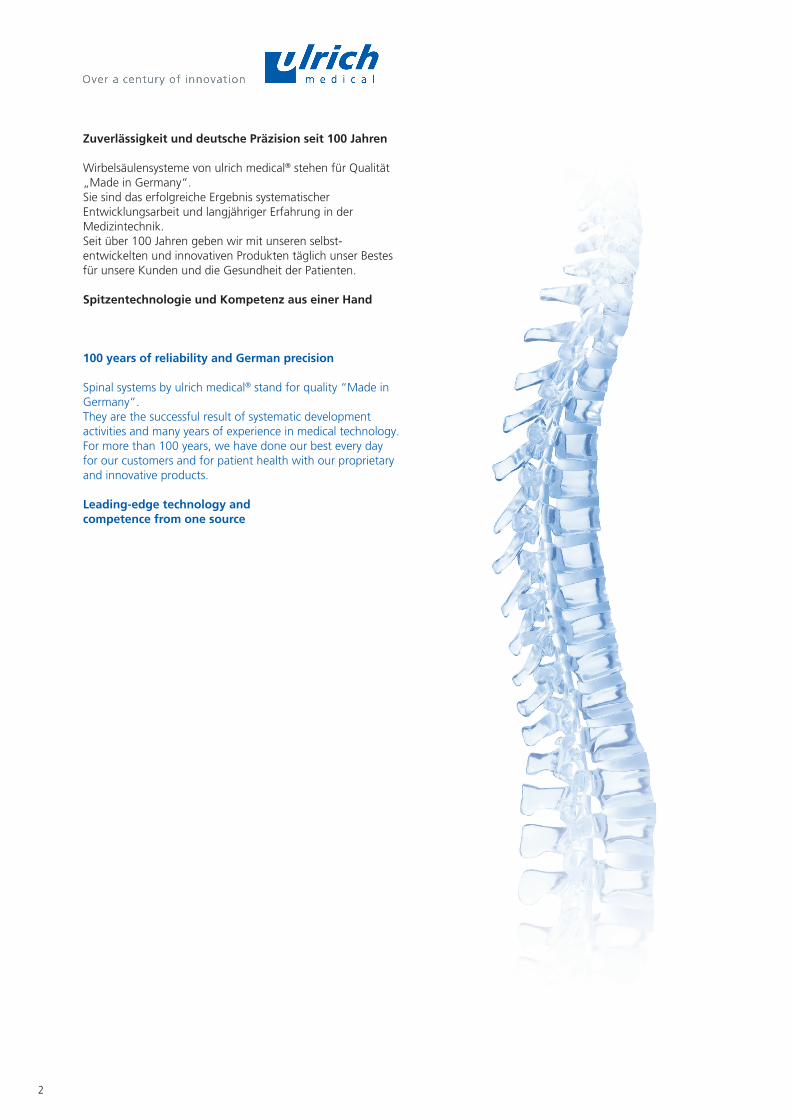
Inhalt l Content
SeitePage
Einleitung 4
5
6
7
16
24
30
39
50
61
65
68
70
72
73
77
Kennzeichnung und Symbole
Anwendung des Systems
uCentum™ Implantate
uCentum™ Instrumente
Operationstechnik �Präparation
�Instrumentierung mit polyaxialen und monoaxialen Schrauben
�Instrumentierung mit vorklemmbaren Schrauben
�Instrumentierung mit vorklemmbaren Langkopfschrauben
�Verbinder
�Haken
�Reposition
�Augmentation mit Zement
�Schraubenentfernung
Siebe
Komponenten
Introduction
Labeling and symbols
System application
uCentum™ implants
uCentum™ instruments
Surgical technique�Preparation
�Instrumentation with polyaxial and monoaxial screws
�Instrumentation with Pre-Fixation screws
�Instrumentation with Pre-Fixation Long-Arm screws
�Connectors
�Hooks
�Reduction
�Cement augmentation
�Removal of the screw
Trays
Components
uCentumTM OP-Technik, offener Zugang l Surgical technique, open approach4
1
Einleitung l Introduction
Allgemeine Informationen
Der Anwender muss sicherstellen, dass die aktuellen Versionen der systembezogenen Gebrauchsanweisungen, OPTechniken und Supplements vorliegen und berücksichtigt werden. Diese sind verfügbar unter: www.ifu.ulrichmedical.com
Das System uCentum™ kann über den offenen und perkutanen Zugang angewendet werden. Die vorliegende OPTechnik beschreibt das Implantat und die Instrumente sowie die Arbeitsschritte für die Anwendung des uCentumTM Systems bei offenem Zugang. Sie ist als alleinige Grundlage für die erfolgreiche Anwendung des Systems nicht ausreichend. Es wird empfohlen, die Operationstechnik bei einem erfahrenen Operateur zu erlernen.
Die kanülierten uCentum™ Schrauben erlauben eine sichere und präzise Platzierung über Führungsdrähte sowie die minimalinvasive bzw. perkutane Applikation. Die Perforationen an der Schraubenspitze ermöglichen die Zementaugmentation durch die bereits implantierte Schraube (außer Schrauben mit Ø 4,5 mm). Das uCentumTM System zeichnet sich durch einen schlanken und niedrig profilierten Schraubenkopf aus. Dadurch besteht Raum für die Knochenanlagerung und gute Sicht zur Fusionskontrolle. Für polyaxiale, monoaxiale und vorklemmbare Schrauben werden die gleichen Instrumente verwendet. Alle Schraubenvarianten können frei kombiniert werden. Die Polyaxialität der vorklemmbaren Schrauben kann durch Anziehen der äußeren Fixierschraube mit Drehmoment blockiert werden, ohne jedoch eine axial oder radial zum Stab gewünschte Bewegung zu unterbinden. Dadurch ergeben sich vielseitige Möglichkeiten für die Reposition des Wirbelkörpers, z.B. der Aufrichtung nach Frakturen oder der Derotation von Skoliosen. Die monoaxiale uCentumTM Schraube weist eine höhere Winkelstabilität im Vergleich zu den polyaxialen Schrauben auf. Diese höhere Stabilität erlaubt kürzere Instrumentierungen und eine vereinfachte Reposition.
In Ländern, in denen das System uBase™ zugelassen ist, kann uCentum™ für die sakrale, iliosakrale und iliakale Instrumentierung mit uBase™ kombiniert werden.
Siehe dazu uBase™ Gebrauchsanweisung WS 7195 und uBase™ OPTechnik WS 7101. Diese sind verfügbar unter: www.ifu.ulrichmedical.com
! Wichtig: Werden in einer Instrumentierung mit offenem Zugang gebogene Stäbe (CS 3809xxx) eingesetzt, ist zu beachten, dass der Stab einen Überstand von mindestens 5 mm haben muss.
Siehe OPTechnik, perkutaner Zugang WS 380102.
Die kleinen Bilder in der Fußzeile zeigen die Instrumente in chronologischer Reihen folge, die für die dargestellten OPSchritte auf einer Doppelseite verwendet werden. Ist das Bild blau unterlegt, wurde das Instrument bereits verwendet.
General information
The user has to ensure, that the latest versions of the systemrelated instructions for use, surgical techniques and supplements are on hand and considered. These are available at: www.ifu.ulrichmedical.com
The uCentum™ system can be used by open and percutaneous approach. This surgical technique describes the implant, the instruments, and the steps involved in the openapproach application of the uCentum™ system. It is not sufficient as the sole basis for a successful application of the system. It is recommended to master the surgical technique with an experienced surgeon.
The cannulated uCentum™ screws permit safe and precise placement via guide wires as well as minimally invasive and percutaneous application. The perforations at the tip of the screw enable cement augmentation through the already implanted screw (except for screws with Ø 4.5 mm). The uCentum™ system is distinguished by a slim, low-profile screw head. It thus allows space for bone grafting and a good view for fusion monitoring. The same instruments are used for polyaxial, monoaxial and pre-fixation screws. All screw variations can be freely combined. The polyaxial design of the pre-fixation screws can be blocked by tightening the external locking screw with torque without, however, inhibiting any desired movement that is axial or radial to the rod. In this way, there are numerous options for reduction the spine, e.g. alignment following fractures or derotation of scoliosis. The monoaxial uCentum™ screw has a higher degree of angular stability as compared to the polyaxial screws. This increased stability allows shorter instrumentation procedures and simplified reduction.
In countries in which the uBase™ system is registered, uCentum™ can be combined with uBase™ for the sacral, iliosacral and iliac instrumentation.
For more information, please consult the uBase™ instructions for use WS 7195 and the uBase™ Surgical Technique WS 7101. These are available at: www.ifu.ulrichmedical.com
! Important: When using curved rods (CS 3809xxx) in an instrumentation with open approach, it must be observed that the rod must project at least 5 mm.
See surgical technique, percutaneous approach WS 380102.
The small pictures at the bottom of the page show the stepbystep application of the instruments that are used as per the surgical steps on the double page. Pictures with instruments that had been used before are bluecolored.
Art. Nr./Art. No. Art. Nr./Art. No.
uCentumTM OP-Technik, offener Zugang l Surgical technique, open approach 5
2
MR Bedingt MR-sicher
Die nichtklinische Prüfung hat erwiesen, dass alle Implantat Komponenten des uCentum™ Systems bedingt MRsicher sind. Weitere Informationen entnehmen Sie bitte der zugehörigen Gebrauchsanweisung. www.ifu.ulrichmedical.com
! Zusätzliche Informationen zur Aufbereitung, Montage und Demontage
Der Anwender muss sicherstellen, dass die aktuelle Version des „Aufbereitungshandbuchs Implantate und Instrumente“ UH 1100 vorliegt und berücksichtigt wird. Für einzelne Instrumente, die in der OPTechnik entsprechend markiert sind , müssen die „Montage und Demontageanleitungen mit speziellen Reinigungshinweisen“ beachtet werden. Diese sind verfügbar unter: www.ifu.ulrichmedical.com.
MR MR conditional
Nonclinical testing has demonstrated that the implants of the uCentum™ system are MR conditional. For further information please refer to the respective IFU.www.ifu.ulrichmedical.com
! Additional information for processing, assembly and disassembly
The user has to ensure, that the latest version of the “Processing manual implants and instruments“ UH 1100 is on hand / present and considered. For individual instruments which are correspondingly marked , the “Assembly and disassembly instructions with special cleaning instructions“ have to be considered. These are available at: www.ifu.ulrichmedical.com.
Kennzeichnung und Symbole l Labeling and symbols
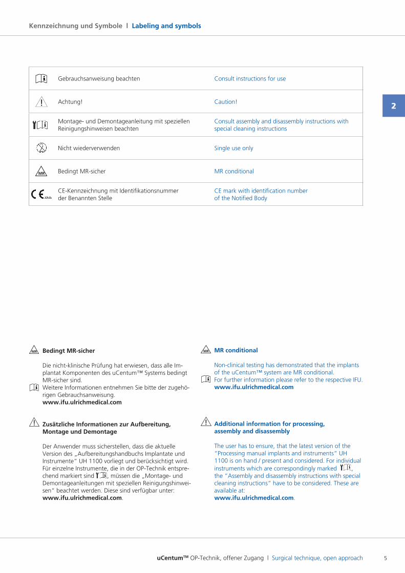
Gebrauchsanweisung beachten Consult instructions for use
! Achtung! Caution!
Montage und Demontageanleitung mit speziellen Reinigungshinweisen beachten
Consult assembly and disassembly instructions with special cleaning instructions
Nicht wiederverwenden Single use only
MR
Bedingt MRsicher MR conditional
CE-Kennzeichnung mit Identifikationsnummer der Benannten Stelle
CE mark with identification number of the Notified Body
uCentumTM OP-Technik, offener Zugang l Surgical technique, open approach6
3
Anwendung des Systems l System application
Bestimmungsgemäßer Gebrauch
uCentum™ ist ein Implantatsystem zur dorsalen operativen Stabilisierung, Fixierung und Korrektur der ausgewachsenen menschlichen Brust und Lendenwirbelsäule, gegebenenfalls unter Einschluss des Sakrums.
Indikationen
Degenerative Bandscheibenerkrankung, Deformität, spinaler Tumor, Spondylolisthese, fehlgeschlagene vorangegangene Fusion, Pseudarthrose, Spinalstenose, Destruktion und Instabilität.
Kontraindikationen
� Patienten mit Fieber oder Leukozytose bei nicht Wirbelsäuleassoziierten Infektionen.
� Patienten mit nachgewiesener Metallallergie oder Neigung zu Fremdkörperreaktionen.
Intended use
uCentum™ is an implant system for the posterior surgical stabilization, fixation and correction of the mature human thoracic and lumbar spine, including the sacrum if necessary.
Indications
Degenerative disk disease, deformity, spinal tumor, spondylolisthesis, failed prior fusion, pseudarthrosis, spinal stenosis, destruction and instability.
Contraindications
� Patients with fever or leukocytosis with nonspine associated infections.
� Patients with a history of metal allergy or who tend to react to foreign bodies.
uCentumTM OP-Technik, offener Zugang l Surgical technique, open approach 7
Fixierschrauben l Locking screws
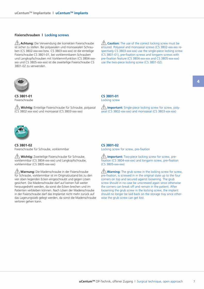
CS 3801-01Locking screw
! Important: Singlepiece locking screw for screw, polyaxial (CS 3802xxxxxx) and monoaxial (CS 3803xxxxxx)
CS 3801-02Locking screw for screw, prefixation
! Important: Twopiece locking screw for screw, prefixation (CS 3804xxxxxx) and longarm screw, prefixation (CS 3805xxxxxx)
! Warning: The grub screw in the locking screw for screw, pre-fixation, is screwed in in the original state up to the four corners on top and secured against loosening. The grub screw should in no case be unscrewed again since otherwise the corners can break off and remain in the patient. After loosening the grub screw in the locking screw, the implant should no longer be laid back on the storage tray since otherwise the grub screw can get lost.
CS 3801-01Fixierschraube
! Wichtig: Einteilige Fixierschraube für Schraube, polyaxial (CS 3802xxxxxx) und monoaxial (CS 3803xxxxxx)
CS 3801-02Fixierschraube für Schraube, vorklemmbar
! Wichtig: Zweiteilige Fixierschraube für Schraube, vorklemmbar (CS 3804xxxxxx) und Langkopfschraube, vorklemmbar (CS 3805xxxxxx)
! Warnung: Die Madenschraube in der Fixierschraube für Schraube, vorklemmbar ist im Originalzustand bis zu den vier oben liegenden Ecken eingeschraubt und gegen Lösen gesichert. Die Madenschraube darf auf keinen Fall weiter herausgedreht werden, da sonst die Ecken brechen und im Patienten verbleiben können. Nach Lösen der Madenschraube in der Fixierschraube darf das Implantat nicht mehr zurück auf das Lagerungssieb gelegt werden, da sonst die Madenschraube verloren gehen kann.
! Achtung: Die Verwendung der korrekten Fixierschraube ist sicher zu stellen. Bei polyaxialen und monoaxialen Schrauben (CS 3802xxxxxx bzw. CS 3803xxxxxx) ist die einteilige Fixierschraube CS 380101, bei vorklemmbaren Schrauben und Langkopfschrauben mit Vorklemmfunktion (CS 3804xxxxxx und CS 3805xxxxxx) ist die zweiteilige Fixierschraube CS 380102 zu verwenden.
! Caution: The use of the correct locking screw must be ensured. Polyaxial and monoaxial screws (CS 3802xxxxxx respectively CS 3803xxxxxx) use the singlepiece locking screw (CS 3801-01), pre-fixation screws and longarm screws with pre-fixation feature (CS 3804-xxx-xxx and CS 3805-xxx-xxx) use the twopiece locking screw (CS 380102).
uCentumTM Implantate l uCentumTM implants
4
uCentumTM OP-Technik, offener Zugang l Surgical technique, open approach8
4
uCentumTM Implantate l uCentumTM implants
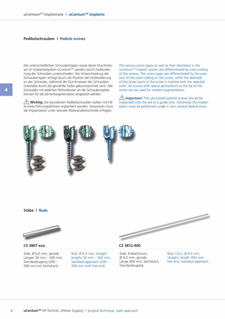
CS 3807-xxx
Stab, Ø 6,0 mm, gerade Längen 30 mm – 500 mm, Standardzugang (200 – 500 mm mit Sechskant)
Rod, Ø 6.0 mm, straight lengths 30 mm – 500 mm, standard approach (200 – 500 mm with hex end)
CS 3812-400
Stab, Kobaltchrom, Ø 6,0 mm, gerade, Länge 400 mm, Sechskant, Standardzugang
Rod, CoCr, Ø 6.0 mm, straight, length 400 mm, hex end, standard approach
Stäbe l Rods
Die unterschiedlichen Schraubentypen sowie deren Durchmesser im Implantatsystem uCentumTM werden durch Farbkodierung der Schrauben unterschieden. Die Unterscheidung der Schraubentypen erfolgt durch die Position der Farbkodierung an der Schraube, während der Durchmesser der Schraubenunterteile durch die gewählte Farbe gekennzeichnet wird. Alle Schrauben mit seitlichen Perforationen an der Schraubenspitze können für die Zementaugmentation eingesetzt werden.
! Wichtig: Die kanülierten Pedikelschrauben sollten mit Hilfe eines Führungsdrahtes implantiert werden. Ansonsten muss die Implantation unter lateraler Bildwandlerkontrolle erfolgen.
The various screw types as well as their diameters in the uCentumTM implant system are differentiated by colorcoding of the screws. The screw types are differentiated by the position of the colorcoding on the screw, while the diameter of the lower parts of the screw is marked with the selected color. All screws with lateral perforations at the tip of the screw can be used for cement augmentation.
! Important: The cannulated pedicle screws should be implanted with the aid of a guide wire. Otherwise the implantation must be performed under Carm control (lateral view).
Pedikelschrauben l Pedicle screws
uCentumTM OP-Technik, offener Zugang l Surgical technique, open approach 9
4
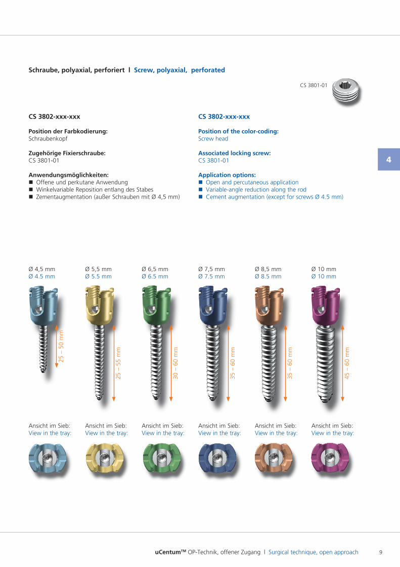
Schraube, polyaxial, perforiert l Screw, polyaxial, perforated
CS 3802-xxx-xxx
Position der Farbkodierung:Schraubenkopf
Zugehörige Fixierschraube:CS 380101
Anwendungsmöglichkeiten: � Offene und perkutane Anwendung � Winkelvariable Reposition entlang des Stabes � Zementaugmentation (außer Schrauben mit Ø 4,5 mm)
CS 3802-xxx-xxx
Position of the color-coding:Screw head
Associated locking screw:CS 380101
Application options: � Open and percutaneous application � Variableangle reduction along the rod � Cement augmentation (except for screws Ø 4.5 mm)
Ansicht im Sieb:View in the tray:
Ansicht im Sieb:View in the tray:
Ansicht im Sieb:View in the tray:
Ansicht im Sieb:View in the tray:
Ansicht im Sieb:View in the tray:
Ansicht im Sieb:View in the tray:
Ø 4,5 mmØ 4.5 mm
Ø 5,5 mmØ 5.5 mm
Ø 6,5 mmØ 6.5 mm
Ø 7,5 mmØ 7.5 mm
Ø 8,5 mmØ 8.5 mm
Ø 10 mmØ 10 mm
25 –
50
mm
25 –
55
mm
30 –
60
mm
35 –
60
mm
35 –
60
mm
45 –
60
mm
CS 380101
uCentumTM OP-Technik, offener Zugang l Surgical technique, open approach10
4
uCentumTM Implantate l uCentumTM implants
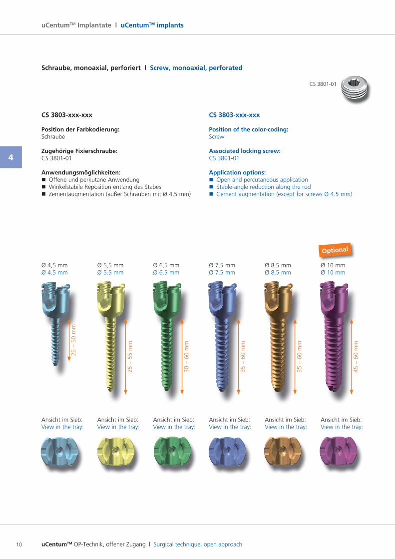
Schraube, monoaxial, perforiert l Screw, monoaxial, perforated
CS 3803-xxx-xxx
Position der Farbkodierung:Schraube
Zugehörige Fixierschraube:CS 380101
Anwendungsmöglichkeiten: � Offene und perkutane Anwendung � Winkelstabile Reposition entlang des Stabes � Zementaugmentation (außer Schrauben mit Ø 4,5 mm)
CS 3803-xxx-xxx
Position of the color-coding:Screw
Associated locking screw:CS 380101
Application options: � Open and percutaneous application � Stableangle reduction along the rod � Cement augmentation (except for screws Ø 4.5 mm)
Ø 4,5 mmØ 4.5 mm
Ø 5,5 mmØ 5.5 mm
Ø 6,5 mmØ 6.5 mm
Ø 7,5 mmØ 7.5 mm
Ø 8,5 mmØ 8.5 mm
Ansicht im Sieb:View in the tray:
Ansicht im Sieb:View in the tray:
Ansicht im Sieb:View in the tray:
Ansicht im Sieb:View in the tray:
Ansicht im Sieb:View in the tray:
25 –
50
mm
25 –
55
mm
30 –
60
mm
35 –
60
mm
35 –
60
mm
Ø 10 mmØ 10 mm
Ansicht im Sieb:View in the tray:
45 –
60
mm
CS 380101
Optional
uCentumTM OP-Technik, offener Zugang l Surgical technique, open approach 11
4
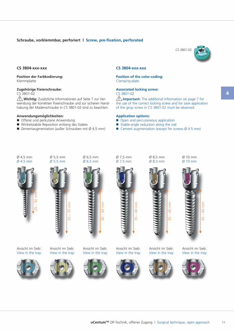
Ø 4,5 mmØ 4.5 mm
Ø 5,5 mmØ 5.5 mm
Ø 6,5 mmØ 6.5 mm
Ø 7,5 mmØ 7.5 mm
Ø 8,5 mmØ 8.5 mm
Ø 10 mmØ 10 mm
Ansicht im Sieb:View in the tray:
Ansicht im Sieb:View in the tray:
Ansicht im Sieb:View in the tray:
Ansicht im Sieb:View in the tray:
Ansicht im Sieb:View in the tray:
Ansicht im Sieb:View in the tray:
25 –
50
mm
25 –
55
mm
30 –
60
mm
35 –
60
mm
35 –
60
mm
45 –
60
mm
Schraube, vorklemmbar, perforiert l Screw, pre-fixation, perforated
CS 3804-xxx-xxx
Position der Farbkodierung:Klemmplatte
Zugehörige Fixierschraube:CS 380102
! Wichtig: Zusätzliche Informationen auf Seite 7 zur Ver wendung der korrekten Fixierschraube und zur sicheren Handhabung der Madenschraube in CS 380102 sind zu beachten.
Anwendungsmöglichkeiten: � Offene und perkutane Anwendung � Winkelstabile Reposition entlang des Stabes � Zementaugmentation (außer Schrauben mit Ø 4,5 mm)
CS 3804-xxx-xxx
Position of the color-coding:Clamping plate
Associated locking screw:CS 380102
! Important: The additional information on page 7 for the use of the correct locking screw and for save application of the grup screw in CS 380102 must be observed.
Application options: � Open and percutaneous application � Stableangle reduction along the rod � Cement augmentation (except for screws Ø 4.5 mm)
CS 380102
uCentumTM OP-Technik, offener Zugang l Surgical technique, open approach12
4
uCentumTM Implantate l uCentumTM implants
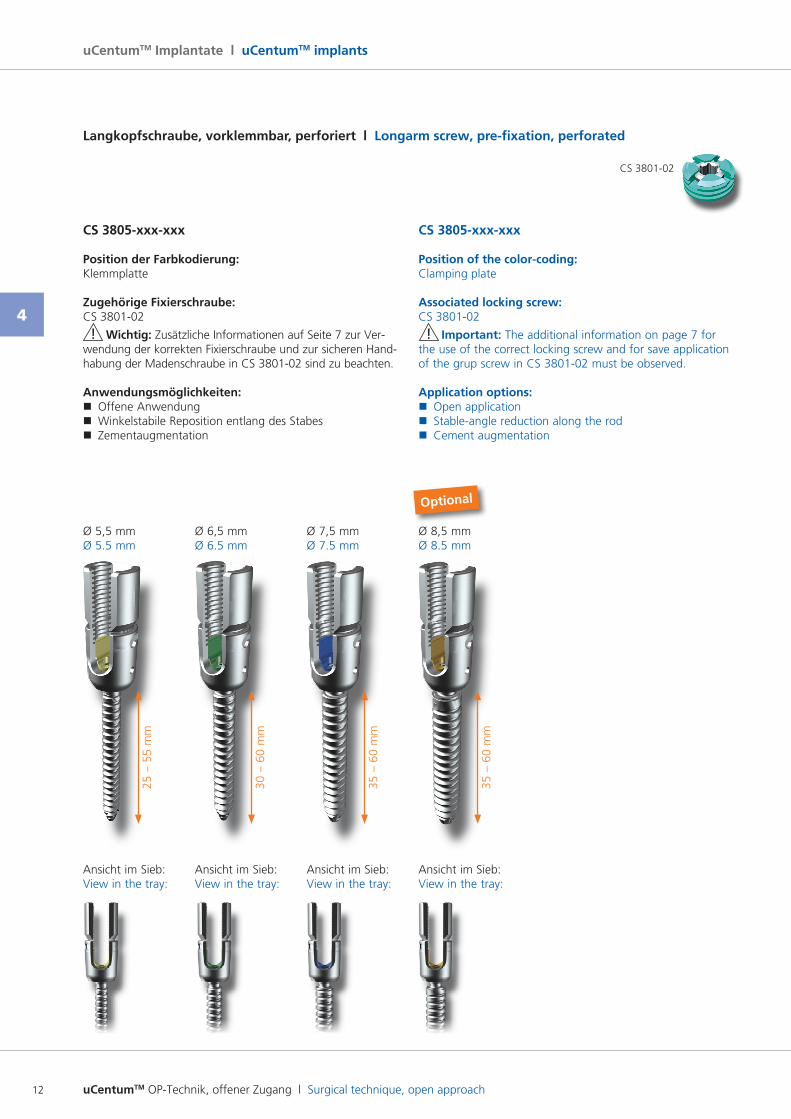
Langkopfschraube, vorklemmbar, perforiert l Longarm screw, pre-fixation, perforated
Ø 5,5 mmØ 5.5 mm
Ø 6,5 mmØ 6.5 mm
Ø 7,5 mmØ 7.5 mm
CS 3805-xxx-xxx
Position der Farbkodierung:Klemmplatte
Zugehörige Fixierschraube:CS 380102
! Wichtig: Zusätzliche Informationen auf Seite 7 zur Ver wendung der korrekten Fixierschraube und zur sicheren Handhabung der Madenschraube in CS 380102 sind zu beachten.
Anwendungsmöglichkeiten: � Offene Anwendung � Winkelstabile Reposition entlang des Stabes � Zementaugmentation
CS 3805-xxx-xxx
Position of the color-coding:Clamping plate
Associated locking screw:CS 380102
! Important: The additional information on page 7 for the use of the correct locking screw and for save application of the grup screw in CS 380102 must be observed.
Application options: � Open application � Stableangle reduction along the rod � Cement augmentation
Ansicht im Sieb:View in the tray:
Ansicht im Sieb:View in the tray:
Ansicht im Sieb:View in the tray:
25 –
55
mm
30 –
60
mm
35 –
60
mm
Ø 8,5 mmØ 8.5 mm
Ansicht im Sieb:View in the tray:
35 –
60
mm
CS 380102
Optional
uCentumTM OP-Technik, offener Zugang l Surgical technique, open approach 13
4
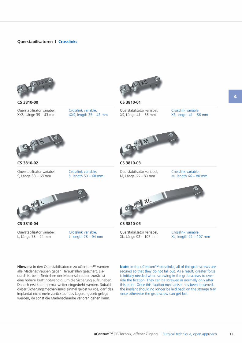
Querstabilisatoren l Crosslinks
CS 3810-00 CS 3810-01
Querstabilisator variabel, XXS, Länge 35 – 43 mm
Querstabilisator variabel, XS, Länge 41 – 56 mm
Crosslink variable, XXS, length 35 – 43 mm
Crosslink variable, XS, length 41 – 56 mm
CS 3810-02 CS 3810-03
Querstabilisator variabel, S, Länge 53 – 68 mm
Querstabilisator variabel, M, Länge 66 – 80 mm
Crosslink variable, S, length 53 – 68 mm
Crosslink variable, M, length 66 – 80 mm
CS 3810-04 CS 3810-05
Querstabilisator variabel, L, Länge 78 – 94 mm
Querstabilisator variabel, XL, Länge 92 – 107 mm
Crosslink variable, L, length 78 – 94 mm
Crosslink variable, XL, length 92 – 107 mm
Hinweis: In den Querstabilisatoren zu uCentum™ werden alle Madenschrauben gegen Herausfallen gesichert. Dadurch ist beim Eindrehen der Madenschrauben zunächst eine höhere Kraft notwendig, um die Sicherung aufzuheben. Danach erst kann normal weiter eingedreht werden. Sobald dieser Sicherungsmechanismus einmal gelöst wurde, darf das Implantat nicht mehr zurück auf das Lagerungssieb gelegt werden, da sonst die Madenschraube verloren gehen kann.
Note: In the uCentum™ crosslinks, all of the grub screws are secured so that they do not fall out. As a result, greater force is initially needed when screwing in the grub screws to override the fixation. They can be screwed in normally only after this point. Once this fixation mechanism has been loosened, the implant should no longer be laid back on the storage tray since otherwise the grub screw can get lost.
uCentumTM OP-Technik, offener Zugang l Surgical technique, open approach14
4
uCentumTM Implantate l uCentumTM implants
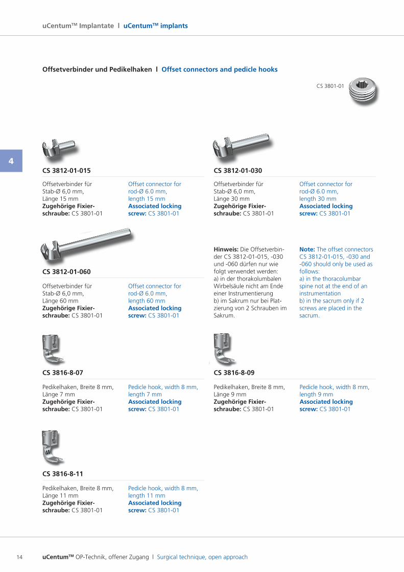
Offsetverbinder und Pedikelhaken l Offset connectors and pedicle hooks
CS 3812-01-015 CS 3812-01-030
Offsetverbinder für StabØ 6,0 mm, Länge 15 mm Zugehörige Fixier- schraube: CS 380101
Offsetverbinder für StabØ 6,0 mm, Länge 30 mm Zugehörige Fixier- schraube: CS 380101
Offset connector for rodØ 6.0 mm, length 15 mm Associated locking screw: CS 380101
Offset connector for rodØ 6.0 mm, length 30 mm Associated locking screw: CS 380101
CS 3812-01-060
Offsetverbinder für StabØ 6,0 mm, Länge 60 mm Zugehörige Fixier- schraube: CS 380101
Offset connector for rodØ 6.0 mm, length 60 mm Associated locking screw: CS 380101
Hinweis: Die Offsetverbinder CS 381201015, 030 und 060 dürfen nur wie folgt verwendet werden: a) in der thorakolumbalen Wirbelsäule nicht am Ende einer Instrumentierung b) im Sakrum nur bei Platzierung von 2 Schrauben im Sakrum.
Note: The offset connectors CS 381201015, 030 and 060 should only be used as follows:a) in the thoracolumbar spine not at the end of an instrumentationb) in the sacrum only if 2 screws are placed in the sacrum.
CS 3816-8-07
CS 3816-8-11
CS 3816-8-09
Pedikelhaken, Breite 8 mm, Länge 7 mm Zugehörige Fixier- schraube: CS 380101
Pedikelhaken, Breite 8 mm, Länge 11 mm Zugehörige Fixier- schraube: CS 380101
Pedikelhaken, Breite 8 mm, Länge 9 mm Zugehörige Fixier- schraube: CS 380101
Pedicle hook, width 8 mm, length 7 mm Associated locking screw: CS 380101
Pedicle hook, width 8 mm, length 11 mm Associated locking screw: CS 380101
Pedicle hook, width 8 mm, length 9 mm Associated locking screw: CS 380101
CS 380101
uCentumTM OP-Technik, offener Zugang l Surgical technique, open approach 15
4
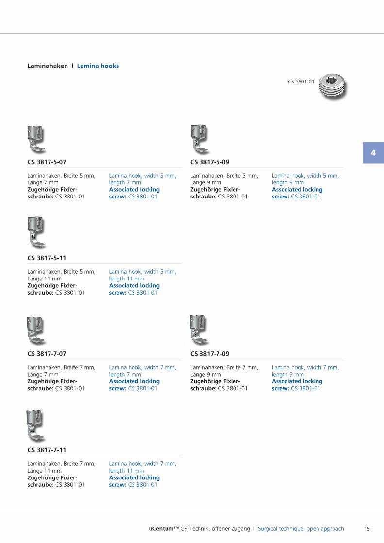
Laminahaken l Lamina hooks
CS 3817-5-07
CS 3817-7-09
CS 3817-7-11
CS 3817-5-11
CS 3817-5-09
CS 3817-7-07
Laminahaken, Breite 5 mm, Länge 7 mm Zugehörige Fixier- schraube: CS 380101
Laminahaken, Breite 7 mm, Länge 9 mm Zugehörige Fixier- schraube: CS 380101
Laminahaken, Breite 7 mm, Länge 11 mm Zugehörige Fixier- schraube: CS 380101
Laminahaken, Breite 5 mm, Länge 11 mm Zugehörige Fixier- schraube: CS 380101
Laminahaken, Breite 5 mm, Länge 9 mm Zugehörige Fixier- schraube: CS 380101
Laminahaken, Breite 7 mm, Länge 7 mm Zugehörige Fixier- schraube: CS 380101
Lamina hook, width 5 mm, length 7 mm Associated locking screw: CS 380101
Lamina hook, width 7 mm, length 9 mm Associated locking screw: CS 380101
Lamina hook, width 7 mm, length 11 mm Associated locking screw: CS 380101
Lamina hook, width 5 mm, length 11 mm Associated locking screw: CS 380101
Lamina hook, width 5 mm, length 9 mm Associated locking screw: CS 380101
Lamina hook, width 7 mm, length 7 mm Associated locking screw: CS 380101
CS 380101
uCentumTM OP-Technik, offener Zugang l Surgical technique, open approach16
5
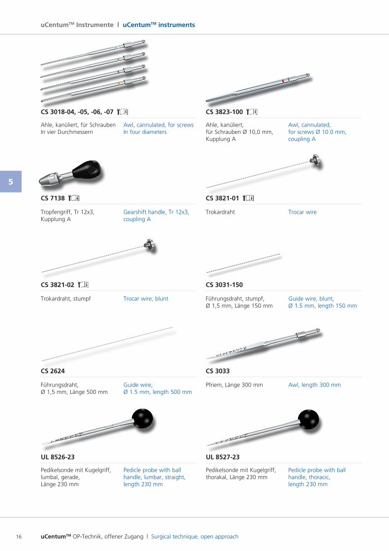
uCentumTM Instrumente l uCentumTM instruments
UL 8526-23 UL 8527-23
Pedikelsonde mit Kugelgriff, lumbal, gerade, Länge 230 mm
Pedikelsonde mit Kugelgriff, thorakal, Länge 230 mm
Pedicle probe with ball handle, lumbar, straight, length 230 mm
Pedicle probe with ball handle, thoracic, length 230 mm
CS 2624 CS 3033
Führungsdraht, Ø 1,5 mm, Länge 500 mm
Pfriem, Länge 300 mmGuide wire, Ø 1.5 mm, length 500 mm
Awl, length 300 mm
CS 3821-02 CS 3031-150
Trokardraht, stumpf Führungsdraht, stumpf, Ø 1,5 mm, Länge 150 mm
Trocar wire, blunt Guide wire, blunt, Ø 1.5 mm, length 150 mm
CS 7138 CS 3821-01
Tropfengriff, Tr 12x3, Kupplung A
TrokardrahtGearshift handle, Tr 12x3, coupling A
Trocar wire
CS 3018-04, -05, -06, -07 CS 3823-100
Ahle, kanüliert, für SchraubenIn vier Durchmessern
Ahle, kanüliert, für Schrauben Ø 10,0 mm, Kupplung A
Awl, cannulated, for screwsIn four diameters
Awl, cannulated, for screws Ø 10.0 mm, coupling A
uCentumTM OP-Technik, offener Zugang l Surgical technique, open approach 17
5
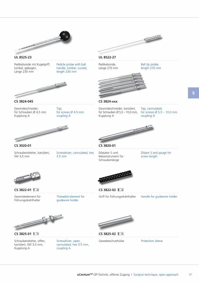
Dilator S and gauge for screw length
UL 8525-23 UL 8522-27
Pedikelsonde mit Kugelgriff, lumbal, gebogen, Länge 230 mm
Pedikelsonde, Länge 270 mm
Pedicle probe with ball handle, lumbar, curved, length 230 mm
Ball tip probe, length 270 mm
CS 3020-01 CS 3820-01
Schraubendreher, kanüliert, SW 3,5 mm
Dilatator S und Messinstrument für Schraubenlänge
Screwdriver, cannulated, hex 3.5 mm
CS 3822-01 CS 3822-02
Gewindeelement für Führungsdrahthalter
Griff für FührungsdrahthalterThreaded element for guidewire holder
Handle for guidewire holder
CS 3825-01 CS 3825-02
Schraubendreher, offen, kanüliert, SW 3,5 mm, Kupplung A
GewebeschutzhülseScrewdriver, open, cannulated, hex 3.5 mm, coupling A
Protection sleeve
CS 3824-xxx
Gewindeschneider, kanüliert, für Schrauben Ø 5,5 – 10,0 mm, Kupplung A
Tap, cannulated, for screws Ø 5.5 – 10.0 mm coupling A
CS 3824-045
Gewindeschneider, für Schrauben Ø 4,5 mm Kupplung A
Tap, for screws Ø 4.5 mm coupling A
uCentumTM OP-Technik, offener Zugang l Surgical technique, open approach18
5
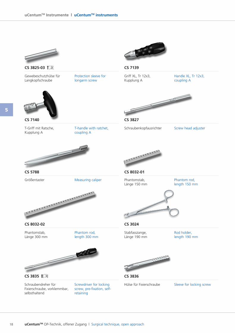
uCentumTM Instrumente l uCentumTM instruments
Hülse für Fixierschraube Sleeve for locking screw
CS 3836CS 3835
Schraubendreher für Fixierschraube, vorklemmbar, selbsthaltend
Screwdriver for locking screw, prefixation, selfretaining
CS 3825-03 CS 7139
Gewebeschutzhülse für Langkopfschraube
Griff XL, Tr 12x3, Kupplung A
Protection sleeve for longarm screw
Handle XL, Tr 12x3, coupling A
CS 7140 CS 3827
TGriff mit Ratsche, Kupplung A
SchraubenkopfausrichterThandle with ratchet, coupling A
Screw head adjuster
CS 5788 CS 8032-01
Größentaster Phantomstab, Länge 150 mm
Measuring caliper Phantom rod, length 150 mm
CS 8032-02 CS 3024
Phantomstab, Länge 300 mm
Stabfasszange, Länge 190 mm
Phantom rod, length 300 mm
Rod holder, length 190 mm
uCentumTM OP-Technik, offener Zugang l Surgical technique, open approach 19
5
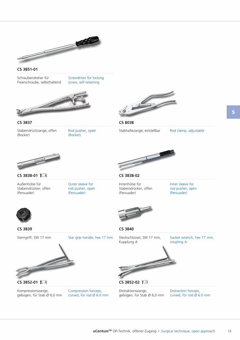
CS 3839 CS 3840
Sterngriff, SW 17 mm Steckschlüssel, SW 17 mm, Kupplung A
Star grip handle, hex 17 mm Socket wrench, hex 17 mm, coupling A
CS 3852-01
Kompressionszange, gebogen, für Stab Ø 6,0 mm
Compression forceps, curved, for rod Ø 6.0 mm
CS 3852-02
Distraktionszange, gebogen, für Stab Ø 6,0 mm
Distraction forceps, curved, for rod Ø 6.0 mm
CS 3838-01 CS 3838-02
Außenhülse für Stabeindrücker, offen (Persuader)
Innenhülse für Stabeindrücker, offen (Persuader)
Outer sleeve for rod pusher, open (Persuader)
Inner sleeve for rod pusher, open (Persuader)
CS 3837 CS 8038
Stabeindrückzange, offen (Rocker)
Stabhaltezange, einstellbarRod pusher, open (Rocker)
Rod clamp, adjustable
Screwdriver for locking screw, selfretaining
Schraubendreher für Fixierschraube, selbsthaltend
CS 3851-01
uCentumTM OP-Technik, offener Zugang l Surgical technique, open approach20
5
uCentumTM Instrumente l uCentumTM instruments
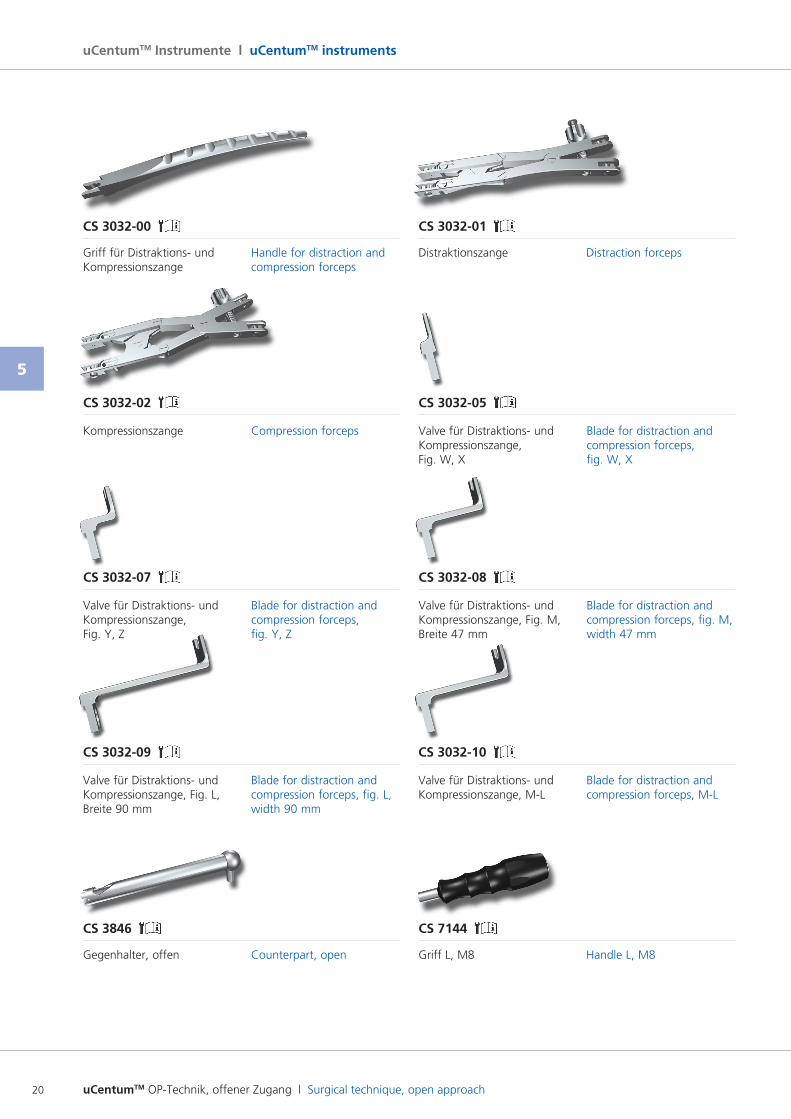
CS 3032-00 CS 3032-01
Griff für Distraktions und Kompressionszange
DistraktionszangeHandle for distraction and compression forceps
Distraction forceps
CS 3032-07 CS 3032-08
Valve für Distraktions und Kompressionszange, Fig. Y, Z
Valve für Distraktions und Kompressionszange, Fig. M, Breite 47 mm
Blade for distraction and compression forceps, fig. Y, Z
Blade for distraction and compression forceps, fig. M, width 47 mm
CS 3032-02 CS 3032-05
Kompressionszange Valve für Distraktions und Kompressionszange, Fig. W, X
Compression forceps Blade for distraction and compression forceps, fig. W, X
CS 3846 CS 7144
Gegenhalter, offen Griff L, M8Counterpart, open Handle L, M8
CS 3032-09 CS 3032-10
Valve für Distraktions und Kompressionszange, Fig. L, Breite 90 mm
Valve für Distraktions und Kompressionszange, ML
Blade for distraction and compression forceps, fig. L, width 90 mm
Blade for distraction and compression forceps, ML
uCentumTM OP-Technik, offener Zugang l Surgical technique, open approach 21
5
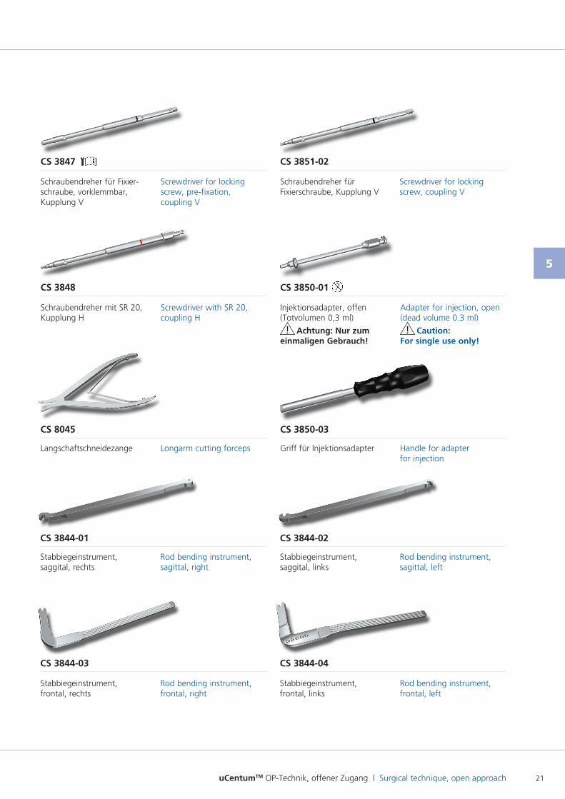
CS 8045 CS 3850-03
Langschaftschneidezange Griff für InjektionsadapterLongarm cutting forceps Handle for adapter for injection
CS 3844-01 CS 3844-02
Stabbiegeinstrument, saggital, rechts
Stabbiegeinstrument, saggital, links
Rod bending instrument, sagittal, right
Rod bending instrument, sagittal, left
Rod bending instrument, frontal, left
CS 3844-04
Stabbiegeinstrument, frontal, links
CS 3844-03
Stabbiegeinstrument, frontal, rechts
Rod bending instrument, frontal, right
CS 3848 CS 3850-01
Schraubendreher mit SR 20, Kupplung H
Injektionsadapter, offen (Totvolumen 0,3 ml)
! Achtung: Nur zum einmaligen Gebrauch!
Screwdriver with SR 20, coupling H
Adapter for injection, open (dead volume 0.3 ml)
! Caution: For single use only!
Screwdriver for locking screw, coupling V
CS 3851-02
Schraubendreher für Fixierschraube, Kupplung V
CS 3847
Schraubendreher für Fixierschraube, vorklemmbar, Kupplung V
Screwdriver for locking screw, prefixation, coupling V
uCentumTM OP-Technik, offener Zugang l Surgical technique, open approach22
5
uCentumTM Instrumente l uCentumTM instruments
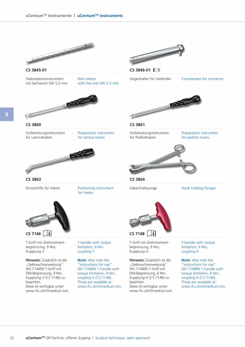
CS 3845-01 CS 3846-01
Stabrotationsinstrument mit Sechskant SW 5,5 mm
Gegenhalter für VerbinderRod rotator with hex end SW 5.5 mm
Counterpart for connector
CS 3860 CS 3861
Vorbereitungsinstrument für Laminahaken
Vorbereitungsinstrument für Pedikelhaken
Preparation instrument for lamina hooks
Preparation instrument for pedicle hooks
CS 7146
TGriff mit Drehmomentbegrenzung, 9 Nm, Kupplung V
Hinweis: Zusätzlich ist die „Gebrauchsanweisung“ WS 714695 TGriff mit DMBegrenzung, 9 Nm, Kupplung V (CS 7146) zu beachten. Diese ist verfügbar unter: www.ifu.ulrichmedical.com.
Thandle with torque limitation, 9 Nm coupling V
Note: Also note the “Instructions for use” WS 714695 Thandle with torque limitation, 9 Nm, coupling V (CS 7146). These are available at: www.ifu.ulrichmedical.com.
CS 7148
TGriff mit Drehmomentbegrenzung, 6 Nm, Kupplung H
Hinweis: Zusätzlich ist die „Gebrauchsanweisung“ WS 714895 TGriff mit DMBegrenzung, 6 Nm, Kupplung H (CS 7148) zu beachten. Diese ist verfügbar unter: www.ifu.ulrichmedical.com.
Thandle with torque limitation, 6 Nm, coupling H
Note: Also note the “Instructions for use” WS 714895 Thandle with torque limitation, 6 Nm, coupling H (CS 7148). These are available at: www.ifu.ulrichmedical.com.
Hook holding forceps
CS 3864
Hakenhaltezange
CS 3863
Einsetzhilfe für Haken Positioning instrument for hooks
uCentumTM OP-Technik, offener Zugang l Surgical technique, open approach 23
5
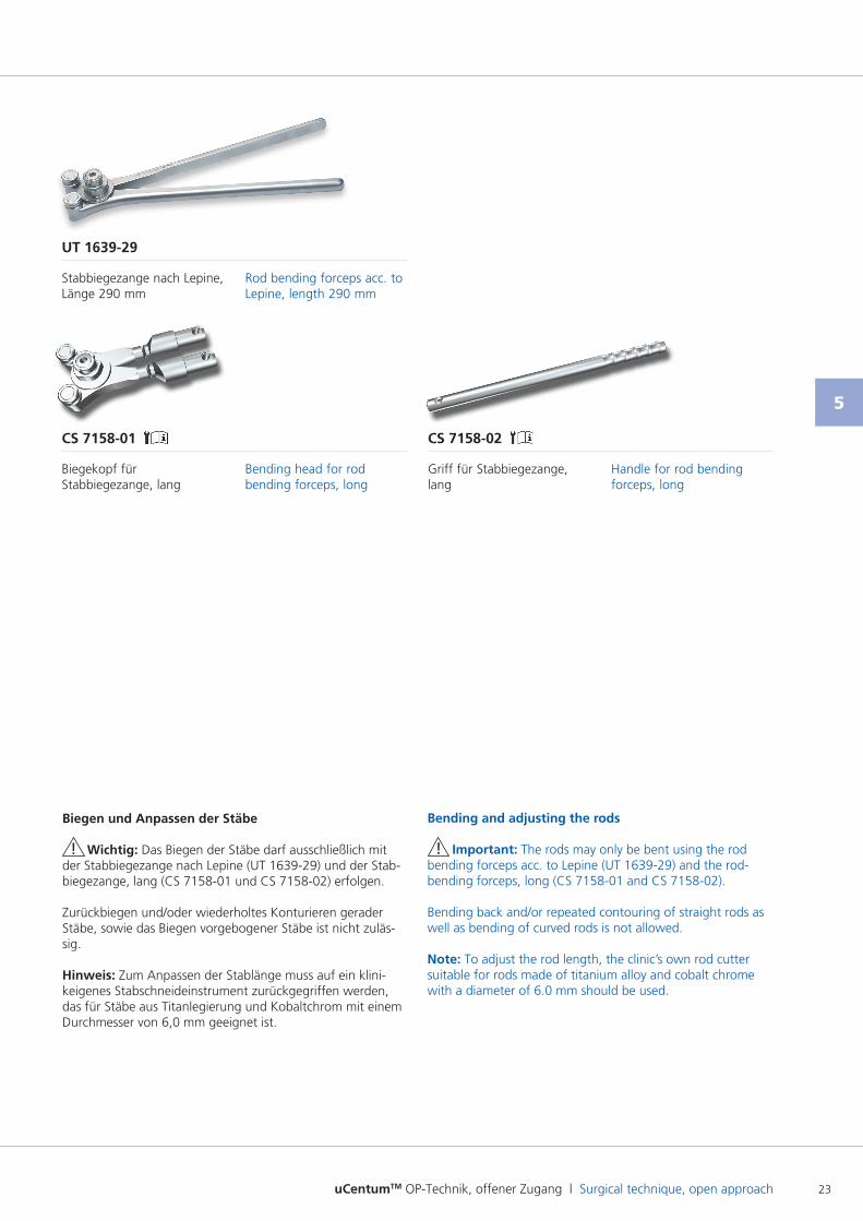
CS 7158-01 CS 7158-02
Biegekopf für Stabbiegezange, lang
Griff für Stabbiegezange, lang
Bending head for rod bending forceps, long
Handle for rod bending forceps, long
UT 1639-29
Stabbiegezange nach Lepine, Länge 290 mm
Rod bending forceps acc. to Lepine, length 290 mm
Biegen und Anpassen der Stäbe
! Wichtig: Das Biegen der Stäbe darf ausschließlich mit der Stabbiegezange nach Lepine (UT 163929) und der Stabbiegezange, lang (CS 715801 und CS 715802) erfolgen.
Zurückbiegen und/oder wiederholtes Konturieren gerader Stäbe, sowie das Biegen vorgebogener Stäbe ist nicht zulässig.
Hinweis: Zum Anpassen der Stablänge muss auf ein klinikeigenes Stabschneideinstrument zurückgegriffen werden, das für Stäbe aus Titanlegierung und Kobaltchrom mit einem Durchmesser von 6,0 mm geeignet ist.
Bending and adjusting the rods
! Important: The rods may only be bent using the rod bending forceps acc. to Lepine (UT 163929) and the rodbending forceps, long (CS 715801 and CS 715802).
Bending back and/or repeated contouring of straight rods as well as bending of curved rods is not allowed.
Note: To adjust the rod length, the clinic’s own rod cutter suitable for rods made of titanium alloy and cobalt chrome with a diameter of 6.0 mm should be used.
uCentumTM OP-Technik, offener Zugang l Surgical technique, open approach24
Operationstechnik l Surgical technique
6.1
CS 2624 CS 3820-01CS 7138 CS 3823-100 CS 3821-01CS 3018-xx
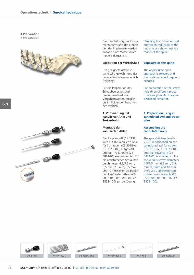
�Präparation�Preparation
Die Handhabung des Instru mentariums und das Einbrin gen der Implantate werden anhand eines Wirbelsäulenmodells dargestellt.
Exposition der Wirbelsäule
Der geeignete offene Zu gang wird gewählt und der dorsale Wirbelsäulenbereich freigelegt.
Für die Präparation des Schraubenloches sind drei unterschiedliche Vorgehensweisen möglich, die im Folgenden beschrieben werden.
1. Vorbereitung mit kanülierter Ahle und Trokardraht
Montage der kanülierten Ahlen
Der Tropfengriff (CS 7138) wird auf die kanülierte Ahle für Schrauben (CS 3018xx, CS 3823100) aufgesetzt und der Trokardraht (CS 382101) eingeschraubt. Für die verschiedenen Schrauben durchmesser 4,5/5,5 mm, 6,5 mm, 7,5 mm, 8,5 mm und 10 mm stehen die passen den kanülierten Ahlen (CS 301804, 05, 06, 07, CS 3823100) zur Verfügung.
Handling the instrument set and the introduction of the implants are shown using a model of the spine.
Exposure of the spine
The appropriate open approach is selected and the posterior spinal region is exposed.
For preparation of the screw hole three different procedures are possible. They are described hereafter.
1. Preparation using a cannulated awl and trocar wire
Assembling the cannulated awls
The gearshift handle (CS 7138) is positioned on the cannulated awl for screws (CS 3018xx, CS 3823100) and the trocar wire (CS 382101) is screwed in. For the various screw diameters 4.5/5.5 mm, 6.5 mm, 7.5 mm, 8.5 mm and 10 mm, there are appropriate cannulated awls available (CS 301804, 05, 06, 07, CS 3823100).
uCentumTM OP-Technik, offener Zugang l Surgical technique, open approach 25
6.1
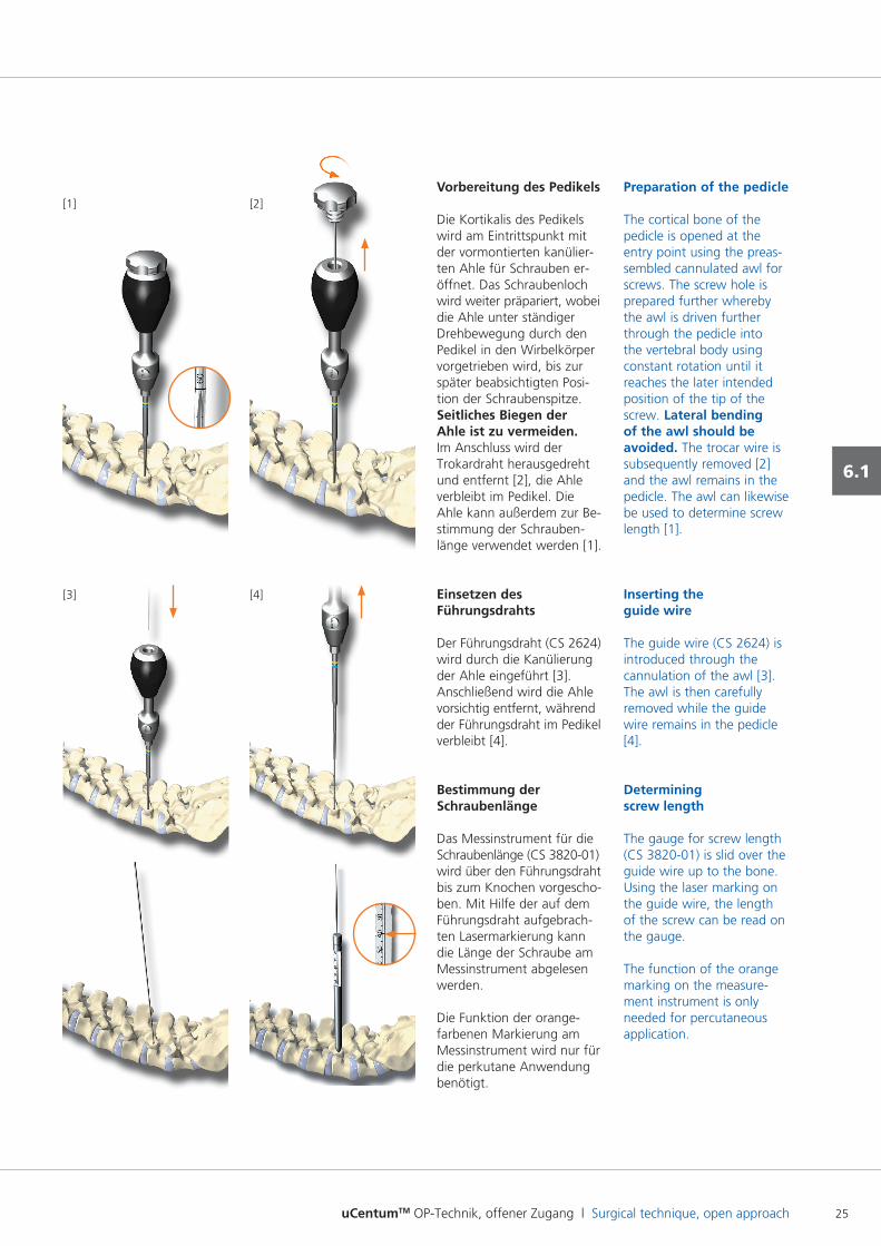
Vorbereitung des Pedikels
Die Kortikalis des Pedikels wird am Eintrittspunkt mit der vormontierten kanülierten Ahle für Schrauben eröffnet. Das Schraubenloch wird weiter präpariert, wobei die Ahle unter ständiger Drehbewegung durch den Pedikel in den Wirbelkörper vorgetrieben wird, bis zur später beabsichtigten Position der Schraubenspitze. Seitliches Biegen der Ahle ist zu vermeiden. Im Anschluss wird der Trokardraht herausgedreht und entfernt [2], die Ahle verbleibt im Pedikel. Die Ahle kann außerdem zur Be stimmung der Schraubenlänge verwendet werden [1].
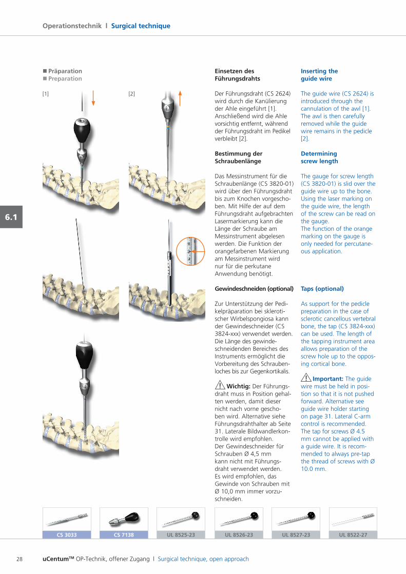
Einsetzen des Führungsdrahts
Der Führungsdraht (CS 2624) wird durch die Kanülierung der Ahle eingeführt [3]. Anschließend wird die Ahle vorsichtig entfernt, während der Führungsdraht im Pedikel verbleibt [4].
Bestimmung der Schraubenlänge
Das Messinstrument für die Schraubenlänge (CS 382001) wird über den Führungsdraht bis zum Knochen vorgeschoben. Mit Hilfe der auf dem Führungsdraht aufgebrachten Lasermarkierung kann die Länge der Schraube am Messinstrument abgelesen werden.
Die Funktion der orangefarbenen Markierung am Messinstrument wird nur für die perkutane Anwendung benötigt.
[3] [4]
Preparation of the pedicle
The cortical bone of the pedicle is opened at the entry point using the preassembled cannulated awl for screws. The screw hole is prepared further whereby the awl is driven further through the pedicle into the vertebral body using constant rotation until it reaches the later intended position of the tip of the screw. Lateral bending of the awl should be avoided. The trocar wire is subsequently removed [2] and the awl remains in the pedicle. The awl can likewise be used to determine screw length [1].
Inserting the guide wire
The guide wire (CS 2624) is introduced through the cannulation of the awl [3]. The awl is then carefully removed while the guide wire remains in the pedicle [4].
Determining screw length
The gauge for screw length (CS 382001) is slid over the guide wire up to the bone. Using the laser marking on the guide wire, the length of the screw can be read on the gauge.
The function of the orange marking on the measurement instrument is only needed for percutaneous application.
[1] [2]
uCentumTM OP-Technik, offener Zugang l Surgical technique, open approach26
Operationstechnik l Surgical technique
6.1
CS 3033 CS 7138 CS 3821-02CS 3018-xxCS 3823-100
�Präparation�Preparation
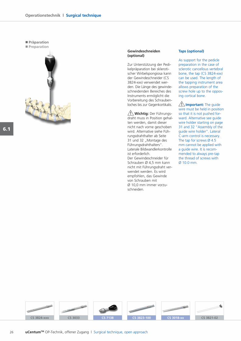
Gewindeschneiden (optional)
Zur Unterstützung der Pedi kelpräparation bei sklerotischer Wirbelspongiosa kann der Gewindeschneider (CS 3824xxx) verwendet werden. Die Länge des gewinde schneidenden Bereiches des Instruments ermöglicht die Vorbereitung des Schrauben loches bis zur Gegenkortikalis.
! Wichtig: Der Führungsdraht muss in Position gehal ten werden, damit dieser nicht nach vorne geschoben wird. Alternative siehe Füh rungsdrahthalter ab Seite 31 und 32 „Montage des Führungsdrahthalters“. Laterale Bildwandlerkontrolle ist erforderlich. Der Gewindeschneider für Schrauben Ø 4,5 mm kann nicht mit Führungsdraht verwendet werden. Es wird empfohlen, das Gewinde von Schrauben mit Ø 10,0 mm immer vorzuschneiden.
Taps (optional)
As support for the pedicle preparation in the case of sclerotic cancellous vertebral bone, the tap (CS 3824xxx) can be used. The length of the tapping instrument area allows preparation of the screw hole up to the opposing cortical bone.
! Important: The guide wire must be held in position so that it is not pushed forward. Alternative see guide wire holder starting on page 31 and 32 “Assembly of the guide wire holder”. Lateral Carm control is necessary. The tap for screws Ø 4.5 mm cannot be applied with a guide wire. It is recommended to always pretap the thread of screws with Ø 10.0 mm.
CS 3824-xxx
uCentumTM OP-Technik, offener Zugang l Surgical technique, open approach 27
6.1
CS 2624 CS 3820-01 CS 3824-xxx
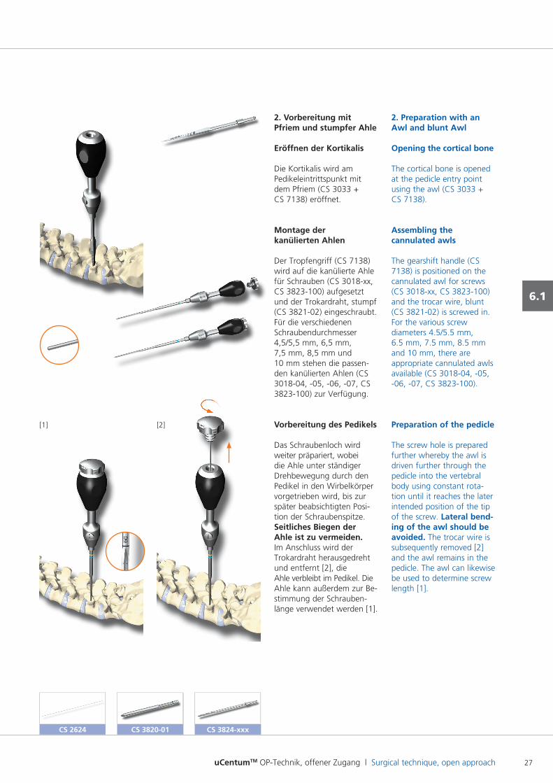
2. Vorbereitung mit Pfriem und stumpfer Ahle
Eröffnen der Kortikalis
Die Kortikalis wird am Pedikeleintrittspunkt mit dem Pfriem (CS 3033 + CS 7138) eröffnet.
Montage der kanülierten Ahlen
Der Tropfengriff (CS 7138) wird auf die kanülierte Ahle für Schrauben (CS 3018xx, CS 3823100) aufgesetzt und der Trokardraht, stumpf (CS 382102) eingeschraubt. Für die verschiedenen Schraubendurchmesser 4,5/5,5 mm, 6,5 mm, 7,5 mm, 8,5 mm und 10 mm stehen die passenden kanülierten Ahlen (CS 301804, 05, 06, 07, CS 3823100) zur Verfügung.
Vorbereitung des Pedikels
Das Schraubenloch wird weiter präpariert, wobei die Ahle unter ständiger Drehbewegung durch den Pedikel in den Wirbelkörper vorgetrieben wird, bis zur später beabsichtigten Position der Schraubenspitze. Seitliches Biegen der Ahle ist zu vermeiden. Im Anschluss wird der Trokardraht herausgedreht und entfernt [2], die Ahle verbleibt im Pedikel. Die Ahle kann außerdem zur Be stimmung der Schraubenlänge verwendet werden [1].
2. Preparation with an Awl and blunt Awl
Opening the cortical bone
The cortical bone is opened at the pedicle entry point using the awl (CS 3033 + CS 7138).
Assembling the cannulated awls
The gearshift handle (CS 7138) is positioned on the cannulated awl for screws (CS 3018xx, CS 3823100) and the trocar wire, blunt (CS 382102) is screwed in. For the various screw diameters 4.5/5.5 mm, 6.5 mm, 7.5 mm, 8.5 mm and 10 mm, there are appropriate cannulated awls available (CS 301804, 05, 06, 07, CS 3823100).
Preparation of the pedicle
The screw hole is prepared further whereby the awl is driven further through the pedicle into the vertebral body using constant rotation until it reaches the later intended position of the tip of the screw. Lateral bend-ing of the awl should be avoided. The trocar wire is subsequently removed [2] and the awl remains in the pedicle. The awl can likewise be used to determine screw length [1].
[1] [2]
uCentumTM OP-Technik, offener Zugang l Surgical technique, open approach28
Operationstechnik l Surgical technique
6.1
CS 3033 CS 7138 UL 8525-23 UL 8526-23 UL 8527-23 UL 8522-27
�Präparation�Preparation
Einsetzen des Führungsdrahts
Der Führungsdraht (CS 2624) wird durch die Kanülierung der Ahle eingeführt [1]. Anschließend wird die Ahle vorsichtig entfernt, während der Führungsdraht im Pedikel verbleibt [2].
Bestimmung der Schraubenlänge
Das Messinstrument für die Schraubenlänge (CS 382001) wird über den Führungsdraht bis zum Knochen vorgeschoben. Mit Hilfe der auf dem Führungsdraht aufgebrachten Lasermarkierung kann die Länge der Schraube am Messinstrument abgelesen werden. Die Funktion der orangefarbenen Markierung am Messinstrument wird nur für die perkutane Anwendung benötigt.
Gewindeschneiden (optional)
Zur Unterstützung der Pedi kelpräparation bei sklerotischer Wirbelspongiosa kann der Gewindeschneider (CS 3824xxx) verwendet werden. Die Länge des gewinde schneidenden Bereiches des Instruments ermöglicht die Vorbereitung des Schrauben loches bis zur Gegenkortikalis.
! Wichtig: Der Führungsdraht muss in Position gehal ten werden, damit dieser nicht nach vorne geschoben wird. Alternative siehe Führungsdrahthalter ab Seite 31. Laterale Bildwandlerkontrolle wird empfohlen. Der Gewindeschneider für Schrauben Ø 4,5 mm kann nicht mit Führungsdraht verwendet werden. Es wird empfohlen, das Gewinde von Schrauben mit Ø 10,0 mm immer vorzuschneiden.
Inserting the guide wire
The guide wire (CS 2624) is introduced through the cannulation of the awl [1]. The awl is then carefully removed while the guide wire remains in the pedicle [2].
Determining screw length
The gauge for screw length (CS 382001) is slid over the guide wire up to the bone. Using the laser marking on the guide wire, the length of the screw can be read on the gauge.The function of the orange marking on the gauge is only needed for percutaneous application.
Taps (optional)
As support for the pedicle preparation in the case of sclerotic cancellous vertebral bone, the tap (CS 3824xxx) can be used. The length of the tapping instrument area allows preparation of the screw hole up to the opposing cortical bone.
! Important: The guide wire must be held in position so that it is not pushed forward. Alternative see guide wire holder starting on page 31. Lateral Carm control is recommended. The tap for screws Ø 4.5 mm cannot be applied with a guide wire. It is recommended to always pretap the thread of screws with Ø 10.0 mm.
[1] [2]
uCentumTM OP-Technik, offener Zugang l Surgical technique, open approach 29
6.1
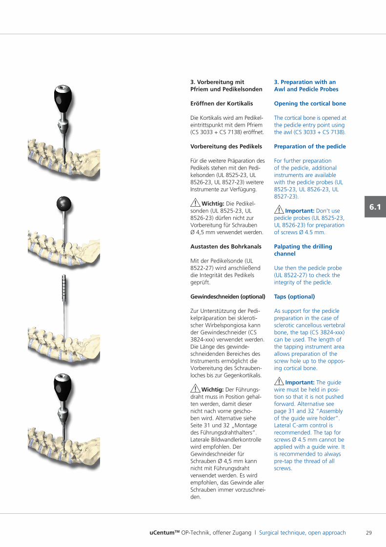
3. Vorbereitung mit Pfriem und Pedikelsonden
Eröffnen der Kortikalis
Die Kortikalis wird am Pedikel eintrittspunkt mit dem Pfriem (CS 3033 + CS 7138) eröffnet.
Vorbereitung des Pedikels
Für die weitere Präparation des Pedikels stehen mit den Pedikelsonden (UL 852523, UL 852623, UL 852723) weitere Instrumente zur Verfügung.
! Wichtig: Die Pedikelsonden (UL 852523, UL 852623) dürfen nicht zur Vorbereitung für Schrauben Ø 4,5 mm verwendet werden.
Austasten des Bohrkanals
Mit der Pedikelsonde (UL 852227) wird anschließend die Integrität des Pedikels geprüft.
Gewindeschneiden (optional)
Zur Unterstützung der Pedi kelpräparation bei sklerotischer Wirbelspongiosa kann der Gewindeschneider (CS 3824xxx) verwendet werden. Die Länge des gewindeschneidenden Bereiches des Instruments ermöglicht die Vorbereitung des Schrauben loches bis zur Gegenkortikalis.
! Wichtig: Der Führungsdraht muss in Position gehal ten werden, damit dieser nicht nach vorne geschoben wird. Alternative siehe Seite 31 und 32 „Montage des Führungsdrahthalters“. Laterale Bildwandlerkontrolle wird empfohlen. Der Gewindeschneider für Schrauben Ø 4,5 mm kann nicht mit Führungsdraht verwendet werden. Es wird empfohlen, das Gewinde aller Schrauben immer vorzuschneiden.
3. Preparation with an Awl and Pedicle Probes
Opening the cortical bone
The cortical bone is opened at the pedicle entry point using the awl (CS 3033 + CS 7138).
Preparation of the pedicle
For further preparation of the pedicle, additional instruments are available with the pedicle probes (UL 852523, UL 852623, UL 852723).
! Important: Don’t use pedicle probes (UL 852523, UL 852623) for preparation of screws Ø 4.5 mm.
Palpating the drilling channel
Use then the pedicle probe (UL 852227) to check the integrity of the pedicle.
Taps (optional)
As support for the pedicle preparation in the case of sclerotic cancellous vertebral bone, the tap (CS 3824xxx) can be used. The length of the tapping instrument area allows preparation of the screw hole up to the opposing cortical bone.
! Important: The guide wire must be held in position so that it is not pushed forward. Alternative see page 31 and 32 “Assembly of the guide wire holder”. Lateral Carm control is recommended. The tap for screws Ø 4.5 mm cannot be applied with a guide wire. It is recommended to always pretap the thread of all screws.
uCentumTM OP-Technik, offener Zugang l Surgical technique, open approach30
Operationstechnik l Surgical technique
6.2
CS 7138
� Instrumentierung mit polyaxialen und monoaxialen Schrauben� Instrumentation with polyaxial and monoaxial screws
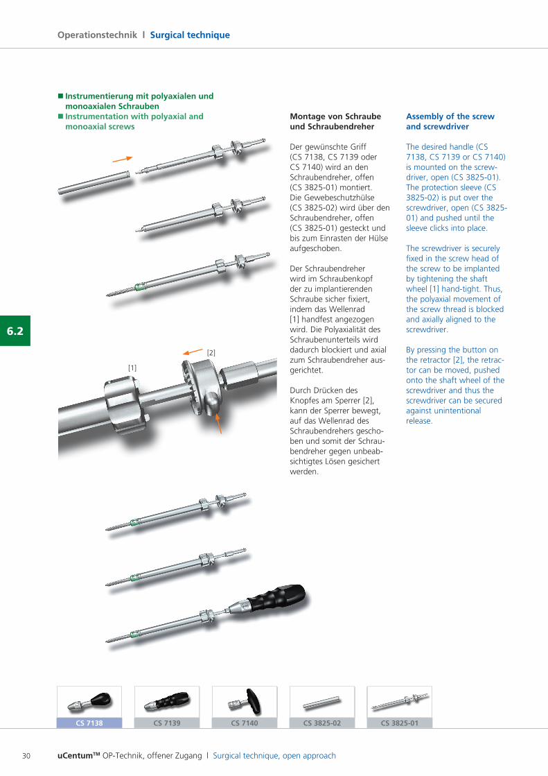
Montage von Schraube und Schraubendreher
Der gewünschte Griff (CS 7138, CS 7139 oder CS 7140) wird an den Schraubendreher, offen (CS 382501) montiert.Die Gewebeschutzhülse (CS 382502) wird über den Schraubendreher, offen (CS 382501) gesteckt und bis zum Einrasten der Hülse aufgeschoben.
Der Schraubendreher wird im Schraubenkopf der zu implantierenden Schraube sicher fixiert, indem das Wellenrad [1] handfest angezogen wird. Die Polyaxialität des Schraubenunterteils wird dadurch blockiert und axial zum Schraubendreher ausgerichtet.
Durch Drücken des Knopfes am Sperrer [2], kann der Sperrer bewegt, auf das Wellenrad des Schraubendrehers geschoben und somit der Schraubendreher gegen unbeabsichtigtes Lösen gesichert werden.
Assembly of the screw and screwdriver
The desired handle (CS 7138, CS 7139 or CS 7140) is mounted on the screwdriver, open (CS 382501).The protection sleeve (CS 382502) is put over the screwdriver, open (CS 382501) and pushed until the sleeve clicks into place.
The screwdriver is securely fixed in the screw head of the screw to be implanted by tightening the shaft wheel [1] handtight. Thus, the polyaxial movement of the screw thread is blocked and axially aligned to the screwdriver.
By pressing the button on the retractor [2], the retractor can be moved, pushed onto the shaft wheel of the screwdriver and thus the screwdriver can be secured against unintentional release.
[1]
[2]
CS 7139 CS 7140 CS 3825-01CS 3825-02
uCentumTM OP-Technik, offener Zugang l Surgical technique, open approach 31
6.2
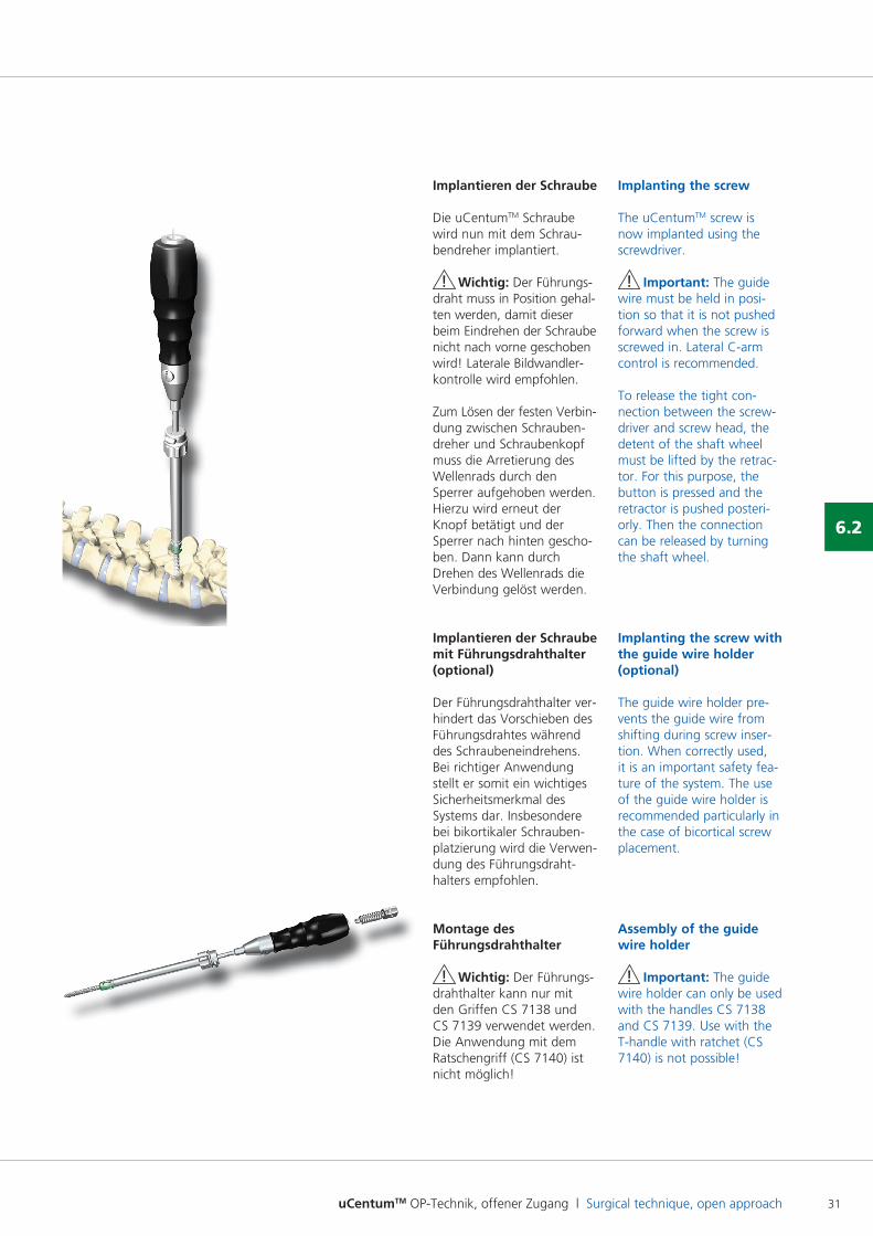
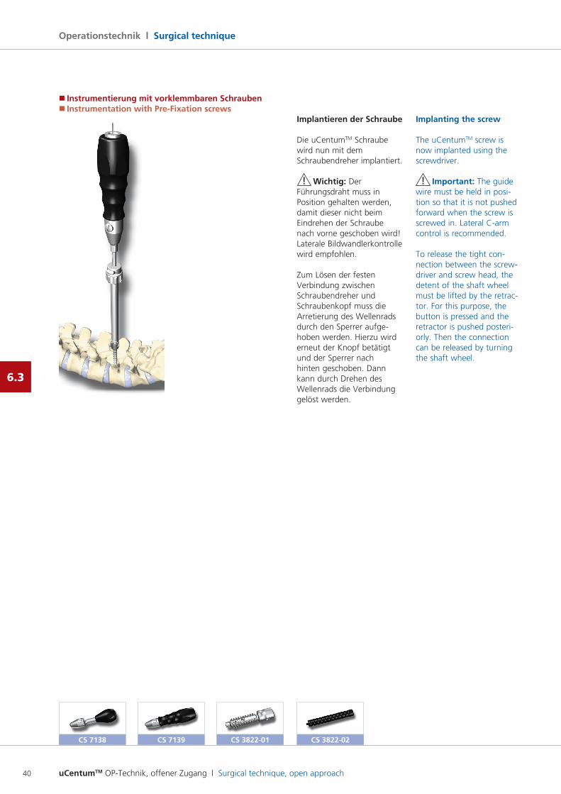
Implantieren der Schraube
Die uCentumTM Schraube wird nun mit dem Schraubendreher implantiert.
! Wichtig: Der Führungsdraht muss in Position gehal ten werden, damit dieser beim Eindrehen der Schraube nicht nach vorne geschoben wird! Laterale Bildwandlerkontrolle wird empfohlen.
Zum Lösen der festen Verbin dung zwischen Schrauben dreher und Schraubenkopf muss die Arretierung des Wellenrads durch den Sperrer aufgehoben werden. Hierzu wird erneut der Knopf betätigt und der Sperrer nach hinten geschoben. Dann kann durch Drehen des Wellenrads die Verbindung gelöst werden.
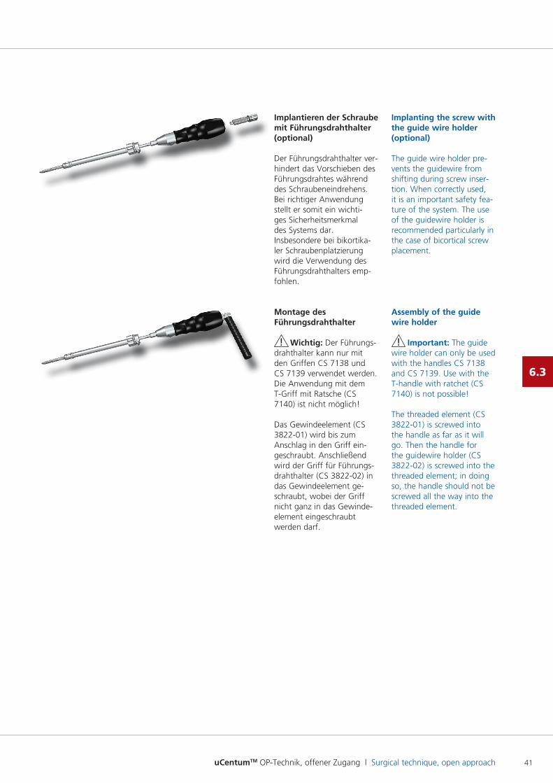
Implantieren der Schraube mit Führungsdrahthalter (optional)
Der Führungsdrahthalter verhindert das Vorschieben des Führungsdrahtes während des Schraubeneindrehens. Bei richtiger Anwendung stellt er somit ein wichtiges Sicherheitsmerkmal des Systems dar. Insbesondere bei bikortikaler Schraubenplatzierung wird die Verwen dung des Führungsdrahthalters empfohlen.
Montage des Führungsdrahthalter
! Wichtig: Der Führungsdrahthalter kann nur mit den Griffen CS 7138 und CS 7139 verwendet werden. Die Anwendung mit dem Ratschengriff (CS 7140) ist nicht möglich!
Implanting the screw
The uCentumTM screw is now implanted using the screwdriver.
! Important: The guide wire must be held in position so that it is not pushed forward when the screw is screwed in. Lateral Carm control is recommended.
To release the tight connection between the screwdriver and screw head, the detent of the shaft wheel must be lifted by the retractor. For this purpose, the button is pressed and the retractor is pushed posteriorly. Then the connection can be released by turning the shaft wheel.
Implanting the screw with the guide wire holder (optional)
The guide wire holder prevents the guide wire from shifting during screw insertion. When correctly used, it is an important safety feature of the system. The use of the guide wire holder is recommended particularly in the case of bicortical screw placement.
Assembly of the guide wire holder
! Important: The guide wire holder can only be used with the handles CS 7138 and CS 7139. Use with the Thandle with ratchet (CS 7140) is not possible!
uCentumTM OP-Technik, offener Zugang l Surgical technique, open approach32
Operationstechnik l Surgical technique
6.2
CS 3827 CS 5788 CS 8032-xx UT 1639-29
� Instrumentierung mit polyaxialen und monoaxialen Schrauben� Instrumentation with polyaxial and monoaxial screws
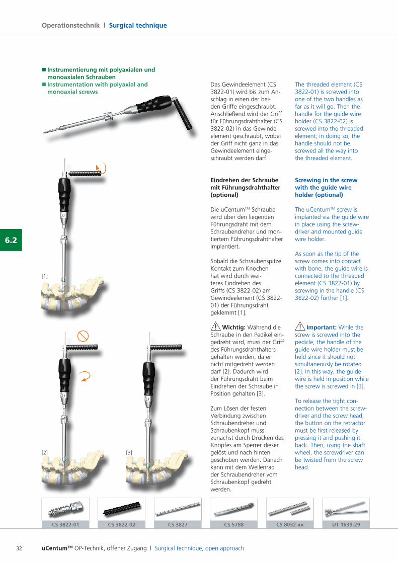
Das Gewindeelement (CS 382201) wird bis zum An schlag in einen der beiden Griffe eingeschraubt. Anschließend wird der Griff für Führungsdrahthalter (CS 382202) in das Gewindeelement geschraubt, wobei der Griff nicht ganz in das Gewindeelement eingeschraubt werden darf.
Eindrehen der Schraube mit Führungsdrahthalter (optional)
Die uCentumTM Schraube wird über den liegenden Führungsdraht mit dem Schraubendreher und montiertem Führungsdrahthalter implantiert.
Sobald die Schraubenspitze Kontakt zum Knochen hat wird durch weiteres Eindrehen des Griffs (CS 382202) am Gewindeelement (CS 382201) der Führungsdraht geklemmt [1].
! Wichtig: Während die Schraube in den Pedikel eingedreht wird, muss der Griff des Führungsdrahthalters gehalten werden, da er nicht mitgedreht werden darf [2]. Dadurch wird der Führungsdraht beim Eindrehen der Schraube in Position gehalten [3].
Zum Lösen der festen Verbindung zwischen Schraubendreher und Schraubenkopf muss zunächst durch Drücken des Knopfes am Sperrer dieser gelöst und nach hinten geschoben werden. Danach kann mit dem Wellenrad der Schraubendreher vom Schraubenkopf gedreht werden.
The threaded element (CS 382201) is screwed into one of the two handles as far as it will go. Then the handle for the guide wire holder (CS 382202) is screwed into the threaded element; in doing so, the handle should not be screwed all the way into the threaded element.
Screwing in the screw with the guide wire holder (optional)
The uCentumTM screw is implanted via the guide wire in place using the screwdriver and mounted guide wire holder.
As soon as the tip of the screw comes into contact with bone, the guide wire is connected to the threaded element (CS 382201) by screwing in the handle (CS 382202) further [1].
! Important: While the screw is screwed into the pedicle, the handle of the guide wire holder must be held since it should not simultaneously be rotated [2]. In this way, the guide wire is held in position while the screw is screwed in [3].
To release the tight connection between the screwdriver and the screw head, the button on the retractor must be first released by pressing it and pushing it back. Then, using the shaft wheel, the screwdriver can be twisted from the screw head.
[1]
[2] [3]
CS 3822-01 CS 3822-02
uCentumTM OP-Technik, offener Zugang l Surgical technique, open approach 33
6.2
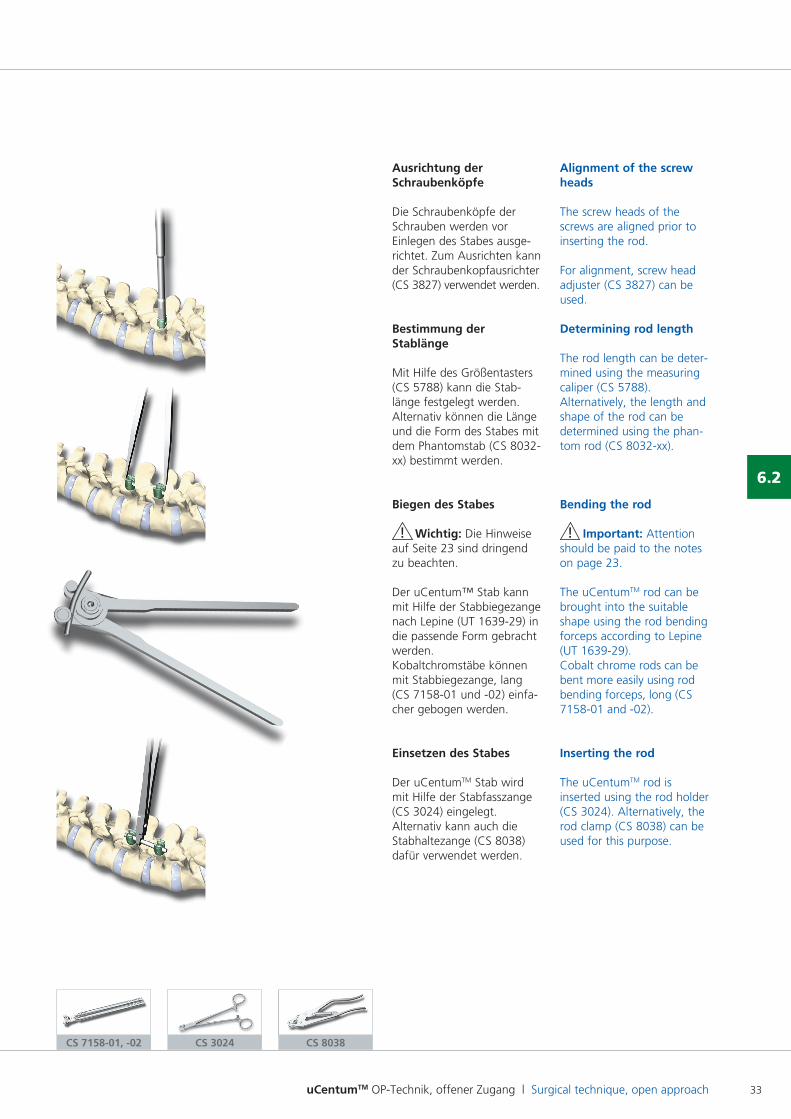
Ausrichtung der Schraubenköpfe
Die Schraubenköpfe der Schrauben werden vor Einlegen des Stabes ausgerichtet. Zum Ausrichten kann der Schraubenkopfausrichter (CS 3827) verwendet werden.
Bestimmung der Stablänge
Mit Hilfe des Größentasters (CS 5788) kann die Stablänge festgelegt werden.Alternativ können die Länge und die Form des Stabes mit dem Phantomstab (CS 8032xx) bestimmt werden.
Biegen des Stabes
! Wichtig: Die Hinweise auf Seite 23 sind dringend zu beachten.
Der uCentum™ Stab kann mit Hilfe der Stabbiegezange nach Lepine (UT 163929) in die passende Form gebracht werden.Kobaltchromstäbe können mit Stabbiegezange, lang (CS 715801 und 02) einfacher gebogen werden.
Einsetzen des Stabes
Der uCentumTM Stab wird mit Hilfe der Stabfasszange (CS 3024) eingelegt. Alternativ kann auch die Stabhaltezange (CS 8038) dafür verwendet werden.
Alignment of the screw heads
The screw heads of the screws are aligned prior to inserting the rod.
For alignment, screw head adjuster (CS 3827) can be used.
Determining rod length
The rod length can be determined using the measuring caliper (CS 5788).Alternatively, the length and shape of the rod can be determined using the phantom rod (CS 8032xx).
Bending the rod
! Important: Attention should be paid to the notes on page 23.
The uCentumTM rod can be brought into the suitable shape using the rod bending forceps according to Lepine (UT 163929).Cobalt chrome rods can be bent more easily using rod bending forceps, long (CS 715801 and 02).
Inserting the rod
The uCentumTM rod is inserted using the rod holder (CS 3024). Alternatively, the rod clamp (CS 8038) can be used for this purpose.
CS 3024 CS 8038CS 7158-01, -02
uCentumTM OP-Technik, offener Zugang l Surgical technique, open approach34
Operationstechnik l Surgical technique
6.2
� Instrumentierung mit polyaxialen und monoaxialen Schrauben� Instrumentation with polyaxial and monoaxial screws
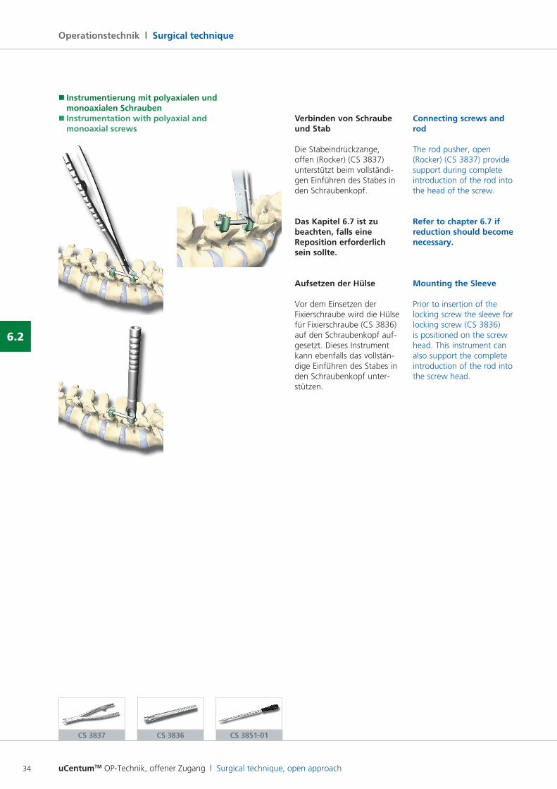
Verbinden von Schraube und Stab
Die Stabeindrückzange, offen (Rocker) (CS 3837) unterstützt beim vollständigen Einführen des Stabes in den Schraubenkopf.
Das Kapitel 6.7 ist zu beachten, falls eine Reposition erforderlich sein sollte.
Aufsetzen der Hülse
Vor dem Einsetzen der Fixierschraube wird die Hülse für Fixierschraube (CS 3836) auf den Schraubenkopf aufgesetzt. Dieses Instrument kann ebenfalls das vollständige Einführen des Stabes in den Schraubenkopf unterstützen.
Connecting screws and rod
The rod pusher, open (Rocker) (CS 3837) provide support during complete introduction of the rod into the head of the screw.
Refer to chapter 6.7 if reduction should become necessary.
Mounting the Sleeve
Prior to insertion of the locking screw the sleeve for locking screw (CS 3836) is positioned on the screw head. This instrument can also support the complete introduction of the rod into the screw head.
CS 3837 CS 3836 CS 3851-01
uCentumTM OP-Technik, offener Zugang l Surgical technique, open approach 35
6.2
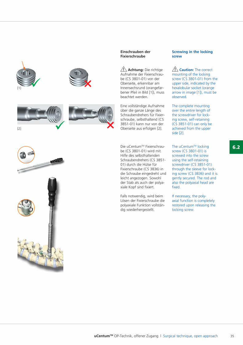
Einschrauben der Fixierschraube
! Achtung: Die richtige Aufnahme der Fixierschraube (CS 380101) von der Oberseite, erkennbar am Innensechsrund (orangefarbener Pfeil in Bild [1]), muss beachtet werden.
Eine vollständige Aufnahme über die ganze Länge des Schraubendrehers für Fixierschraube, selbsthaltend (CS 385101) kann nur von der Oberseite aus erfolgen [2].
Die uCentumTM Fixierschraube (CS 380101) wird mit Hilfe des selbsthaltenden Schraubendrehers (CS 385101) durch die Hülse für Fixierschraube (CS 3836) in die Schraube eingedreht und leicht angezogen. Sowohl der Stab als auch der polyaxiale Kopf sind fixiert.
Falls notwendig, wird beim Lösen der Fixierschraube die polyaxiale Funktion vollständig wiederhergestellt.
ü r[1]
ü r[2]
Screwing in the locking screw
! Caution: The correct mounting of the locking screw (CS 380101) from the upper side, indicated by the hexalobular socket (orange arrow in image [1]), must be observed.
The complete mounting over the entire length of the screwdriver for locking screw, selfretaining (CS 385101) can only be achieved from the upper side [2].
The uCentumTM locking screw (CS 380101) is screwed into the screw using the selfretaining screwdriver (CS 385101) through the sleeve for locking screw (CS 3836) and it is gently secured. The rod and also the polyaxial head are fixed.
If necessary, the polyaxial function is completely restored upon releasing the locking screw.
uCentumTM OP-Technik, offener Zugang l Surgical technique, open approach36
Operationstechnik l Surgical technique
6.2
CS 3032-00 CS 3032-01 CS 3032-02
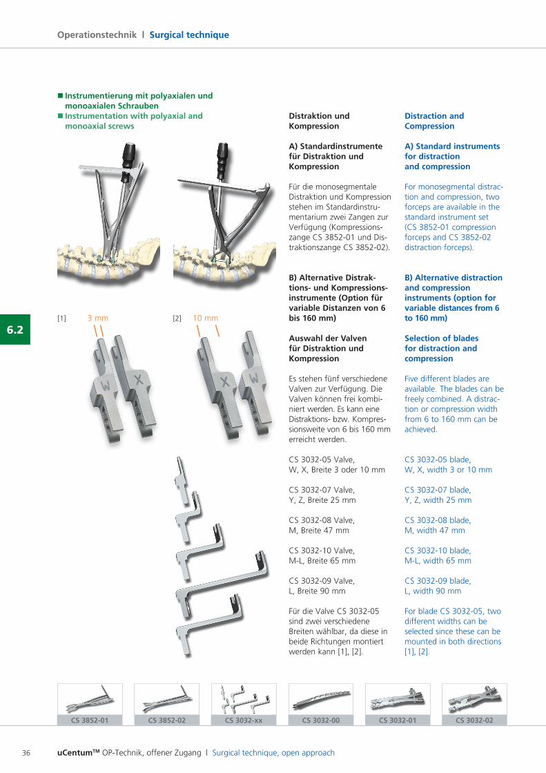
Distraktion und Kompression
A) Standardinstrumente für Distraktion und Kompression
Für die monosegmentale Distraktion und Kompression stehen im Standardinstrumentarium zwei Zangen zur Verfügung (Kompressionszange CS 385201 und Distraktionszange CS 385202).
B) Alternative Distrak- tions- und Kompressions-instrumente (Option für variable Distanzen von 6 bis 160 mm)
Auswahl der Valven für Distraktion und Kompression
Es stehen fünf verschiedene Valven zur Verfügung. Die Valven können frei kombiniert werden. Es kann eine Distraktions bzw. Kompressionsweite von 6 bis 160 mm erreicht werden.
CS 303205 Valve, W, X, Breite 3 oder 10 mm
CS 303207 Valve, Y, Z, Breite 25 mm
CS 303208 Valve, M, Breite 47 mm
CS 303210 Valve, ML, Breite 65 mm
CS 303209 Valve, L, Breite 90 mm
Für die Valve CS 303205 sind zwei verschiedene Breiten wählbar, da diese in beide Richtungen montiert werden kann [1], [2].
Distraction and Compression
A) Standard instruments for distraction and compression
For monosegmental distraction and compression, two forceps are available in the standard instrument set (CS 385201 compression forceps and CS 385202 distraction forceps).
B) Alternative distraction and compression instruments (option for variable distances from 6 to 160 mm)
Selection of blades for distraction and compression
Five different blades are available. The blades can be freely combined. A distraction or compression width from 6 to 160 mm can be achieved.
CS 303205 blade, W, X, width 3 or 10 mm
CS 303207 blade, Y, Z, width 25 mm
CS 303208 blade, M, width 47 mm
CS 303210 blade, ML, width 65 mm
CS 303209 blade, L, width 90 mm
For blade CS 303205, two different widths can be selected since these can be mounted in both directions [1], [2].
CS 3852-01 CS 3852-02
[1] [2]3 mm 10 mm
� Instrumentierung mit polyaxialen und monoaxialen Schrauben� Instrumentation with polyaxial and monoaxial screws
CS 3032-xx
uCentumTM OP-Technik, offener Zugang l Surgical technique, open approach 37
6.2
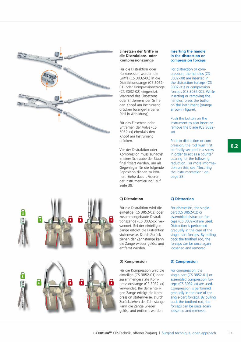
Einsetzen der Griffe in die Distraktions- oder Kompressionszange
Für die Distraktion oder Kompression werden die Griffe (CS 303200) in die Distraktionszange (CS 303201) oder Kompressionszange (CS 303202) eingesetzt. Während des Einsetzens oder Entfernens der Griffe den Knopf am Instrument drücken (orangefarbener Pfeil in Abbildung).
Für das Einsetzen oder Entfernen der Valve (CS 3032xx) ebenfalls den Knopf am Instrument drücken.
Vor der Distraktion oder Kompression muss zunächst in einer Schraube der Stab final fixiert werden, um als Gegenlager für die folgende Reposition dienen zu können. Siehe dazu „Fixieren der Instrumentierung“ auf Seite 38.
C) Distraktion
Für die Distraktion wird die einteilige (CS 385202) oder zusammengebaute Distraktionszange (CS 3032xx) ver wendet. Bei der einteiligen Zange erfolgt die Distraktion stufenweise. Durch Zurückziehen der Zahnstange kann die Zange wieder gelöst und entfernt werden.
D) Kompression
Für die Kompression wird die einteilige (CS 385201) oder zusammengesetzte Kompressionszange (CS 3032xx) verwendet. Bei der einteili gen Zange erfolgt die Kom pression stufenweise. Durch Zurückziehen der Zahnstange kann die Zange wieder gelöst und entfernt werden.
Inserting the handle in the distraction or compression forceps
For distraction or compression, the handles (CS 303200) are inserted in the distraction forceps (CS 303201) or compression forceps (CS 303202). While inserting or removing the handles, press the button on the instrument (orange arrow in figure).
Push the button on the instrument to also insert or remove the blade (CS 3032xx).
Prior to distraction or compression, the rod must first be finally secured in a screw in order to act as a counter bearing for the following reduction. For more information on this, see “Securing the instrumentation” on page 38.
C) Distraction
For distraction, the single part (CS 385202) or assembled distraction forceps (CS 3032xx) are used. Distraction is performed gradually in the case of the singlepart forceps. By pulling back the toothed rod, the forceps can be once again loosened and removed.
D) Compression
For compression, the singlepart (CS 385201) or assembled compression forceps (CS 3032xx) are used. Compression is performed gradually in the case of the singlepart forceps. By pulling back the toothed rod, the forceps can be once again loosened and removed.
uCentumTM OP-Technik, offener Zugang l Surgical technique, open approach38
Operationstechnik l Surgical technique
6.2
CS 7138
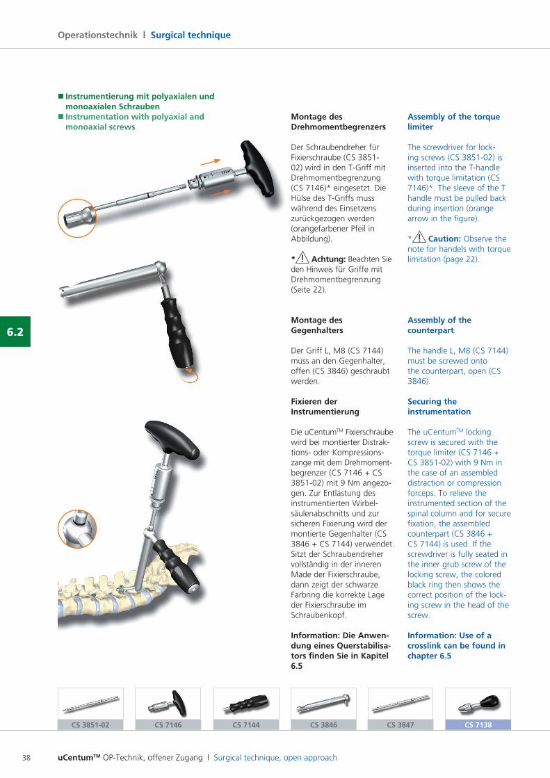
Montage des Drehmomentbegrenzers
Der Schraubendreher für Fixierschraube (CS 385102) wird in den TGriff mit Drehmomentbegrenzung (CS 7146)* eingesetzt. Die Hülse des TGriffs muss während des Einsetzens zurückgezogen werden (orangefarbener Pfeil in Abbildung).
* ! Achtung: Beachten Sie den Hinweis für Griffe mit Drehmomentbegrenzung (Seite 22).
Montage des Gegenhalters
Der Griff L, M8 (CS 7144) muss an den Gegenhalter, offen (CS 3846) geschraubt werden.
Fixieren der Instrumentierung
Die uCentumTM Fixierschraube wird bei montierter Distrak tions oder Kompressionszange mit dem Drehmoment begrenzer (CS 7146 + CS 385102) mit 9 Nm angezogen. Zur Entlastung des instrumentierten Wirbelsäulenabschnitts und zur sicheren Fixierung wird der montierte Gegenhalter (CS 3846 + CS 7144) verwendet.Sitzt der Schraubendreher vollständig in der inneren Made der Fixierschraube, dann zeigt der schwarze Farbring die korrekte Lage der Fixierschraube im Schraubenkopf.
Information: Die Anwen- dung eines Querstabilisa-tors finden Sie in Kapitel 6.5
Assembly of the torque limiter
The screwdriver for locking screws (CS 385102) is inserted into the Thandle with torque limitation (CS 7146)*. The sleeve of the T handle must be pulled back during insertion (orange arrow in the figure).
* ! Caution: Observe the note for handels with torque limitation (page 22).
Assembly of the counterpart
The handle L, M8 (CS 7144) must be screwed onto the counterpart, open (CS 3846).
Securing the instrumentation
The uCentumTM locking screw is secured with the torque limiter (CS 7146 + CS 385102) with 9 Nm in the case of an assembled distraction or compression forceps. To relieve the instrumented section of the spinal column and for secure fixation, the assembled counterpart (CS 3846 + CS 7144) is used. If the screwdriver is fully seated in the inner grub screw of the locking screw, the colored black ring then shows the correct position of the locking screw in the head of the screw.
Information: Use of a crosslink can be found in chapter 6.5
CS 3851-02 CS 7146 CS 7144 CS 3847CS 3846
� Instrumentierung mit polyaxialen und monoaxialen Schrauben� Instrumentation with polyaxial and monoaxial screws
uCentumTM OP-Technik, offener Zugang l Surgical technique, open approach 39
6.3
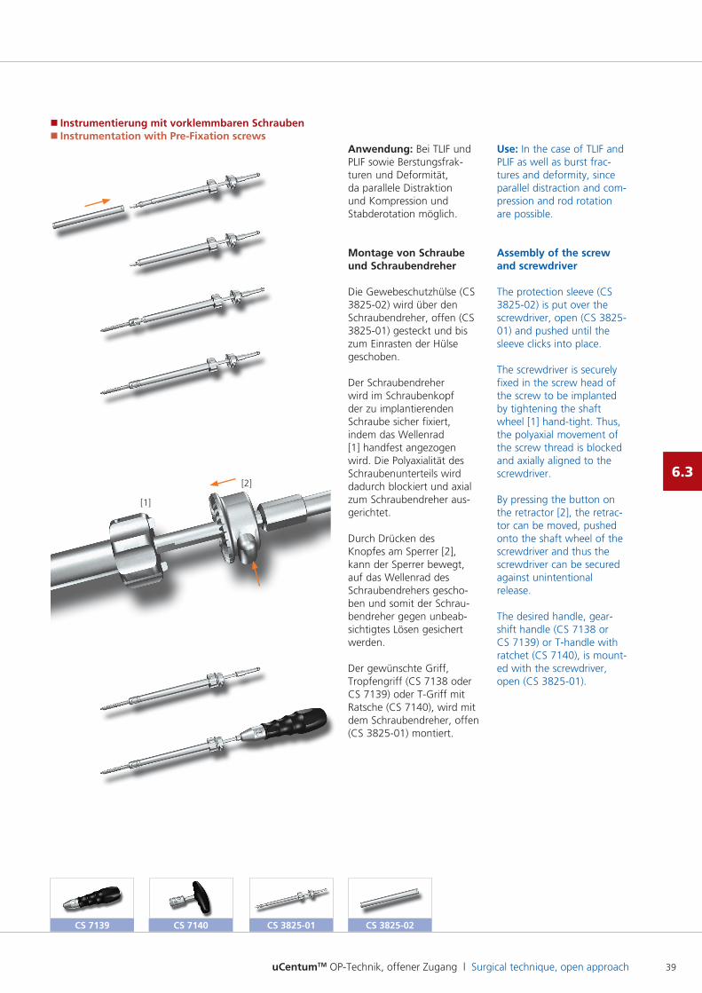
Anwendung: Bei TLIF und PLIF sowie Berstungsfrakturen und Deformität, da parallele Distraktion und Kompression und Stabderotation möglich.
Montage von Schraube und Schraubendreher
Die Gewebeschutzhülse (CS 382502) wird über den Schraubendreher, offen (CS 382501) gesteckt und bis zum Einrasten der Hülse geschoben.
Der Schraubendreher wird im Schraubenkopf der zu implantierenden Schraube sicher fixiert, indem das Wellenrad [1] handfest angezogen wird. Die Polyaxialität des Schraubenunterteils wird dadurch blockiert und axial zum Schraubendreher ausgerichtet.
Durch Drücken des Knopfes am Sperrer [2], kann der Sperrer bewegt, auf das Wellenrad des Schraubendrehers geschoben und somit der Schraubendreher gegen unbeabsichtigtes Lösen gesichert werden.
Der gewünschte Griff, Tropfengriff (CS 7138 oder CS 7139) oder TGriff mit Ratsche (CS 7140), wird mit dem Schraubendreher, offen (CS 382501) montiert.
Use: In the case of TLIF and PLIF as well as burst fractures and deformity, since parallel distraction and compression and rod rotation are possible.
Assembly of the screw and screwdriver
The protection sleeve (CS 382502) is put over the screwdriver, open (CS 382501) and pushed until the sleeve clicks into place.
The screwdriver is securely fixed in the screw head of the screw to be implanted by tightening the shaft wheel [1] handtight. Thus, the polyaxial movement of the screw thread is blocked and axially aligned to the screwdriver.
By pressing the button on the retractor [2], the retractor can be moved, pushed onto the shaft wheel of the screwdriver and thus the screwdriver can be secured against unintentional release.
The desired handle, gearshift handle (CS 7138 or CS 7139) or Thandle with ratchet (CS 7140), is mounted with the screwdriver, open (CS 382501).
CS 7139 CS 7140 CS 3825-01 CS 3825-02
� Instrumentierung mit vorklemmbaren Schrauben� Instrumentation with Pre-Fixation screws
[1]
[2]
uCentumTM OP-Technik, offener Zugang l Surgical technique, open approach40
Operationstechnik l Surgical technique
6.3
CS 7138 CS 7139 CS 3822-01 CS 3822-02
Implantieren der Schraube
Die uCentumTM Schraube wird nun mit dem Schraubendreher implantiert.
! Wichtig: Der Führungsdraht muss in Position gehalten werden, damit dieser nicht beim Eindrehen der Schraube nach vorne geschoben wird! Laterale Bildwandlerkontrolle wird empfohlen.
Zum Lösen der festen Verbindung zwischen Schraubendreher und Schraubenkopf muss die Arretierung des Wellenrads durch den Sperrer aufgehoben werden. Hierzu wird erneut der Knopf betätigt und der Sperrer nach hinten geschoben. Dann kann durch Drehen des Wellenrads die Verbindung gelöst werden.
Implanting the screw
The uCentumTM screw is now implanted using the screwdriver.
! Important: The guide wire must be held in position so that it is not pushed forward when the screw is screwed in. Lateral Carm control is recommended.
To release the tight connection between the screwdriver and screw head, the detent of the shaft wheel must be lifted by the retractor. For this purpose, the button is pressed and the retractor is pushed posteriorly. Then the connection can be released by turning the shaft wheel.
� Instrumentierung mit vorklemmbaren Schrauben� Instrumentation with Pre-Fixation screws
uCentumTM OP-Technik, offener Zugang l Surgical technique, open approach 41
6.3
Implantieren der Schraube mit Führungsdrahthalter (optional)
Der Führungsdrahthalter verhindert das Vorschieben des Führungsdrahtes während des Schraubeneindrehens. Bei richtiger Anwendung stellt er somit ein wichtiges Sicherheitsmerkmal des Systems dar. Insbesondere bei bikortikaler Schraubenplatzierung wird die Verwendung des Führungsdrahthalters empfohlen.
Montage des Führungsdrahthalter
! Wichtig: Der Führungsdrahthalter kann nur mit den Griffen CS 7138 und CS 7139 verwendet werden. Die Anwendung mit dem TGriff mit Ratsche (CS 7140) ist nicht möglich!
Das Gewindeelement (CS 382201) wird bis zum Anschlag in den Griff eingeschraubt. Anschließend wird der Griff für Führungsdrahthalter (CS 382202) in das Gewindeelement ge schraubt, wobei der Griff nicht ganz in das Gewindeelement eingeschraubt werden darf.
Implanting the screw with the guide wire holder (optional)
The guide wire holder prevents the guidewire from shifting during screw insertion. When correctly used, it is an important safety feature of the system. The use of the guidewire holder is recommended particularly in the case of bicortical screw placement.
Assembly of the guide wire holder
! Important: The guide wire holder can only be used with the handles CS 7138 and CS 7139. Use with the Thandle with ratchet (CS 7140) is not possible!
The threaded element (CS 382201) is screwed into the handle as far as it will go. Then the handle for the guidewire holder (CS 382202) is screwed into the threaded element; in doing so, the handle should not be screwed all the way into the threaded element.
uCentumTM OP-Technik, offener Zugang l Surgical technique, open approach42
Operationstechnik l Surgical technique
6.3
CS 3822-01
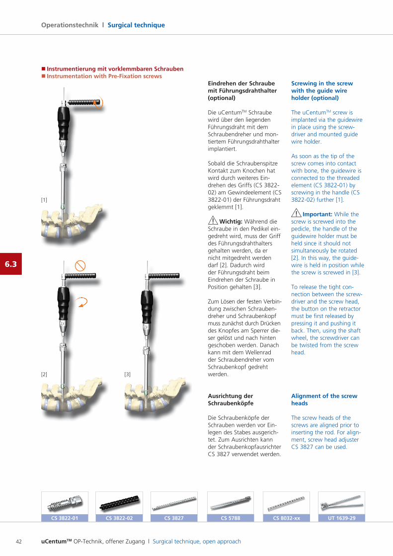
Eindrehen der Schraube mit Führungsdrahthalter (optional)
Die uCentumTM Schraube wird über den liegenden Führungsdraht mit dem Schraubendreher und montiertem Führungsdrahthalter implantiert.
Sobald die Schraubenspitze Kontakt zum Knochen hat wird durch weiteres Eindrehen des Griffs (CS 382202) am Gewindeelement (CS 382201) der Führungsdraht geklemmt [1].
! Wichtig: Während die Schraube in den Pedikel eingedreht wird, muss der Griff des Führungsdrahthalters gehalten werden, da er nicht mitgedreht werden darf [2]. Dadurch wird der Führungsdraht beim Eindrehen der Schraube in Position gehalten [3].
Zum Lösen der festen Verbin dung zwischen Schraubendreher und Schraubenkopf muss zunächst durch Drücken des Knopfes am Sperrer dieser gelöst und nach hinten geschoben werden. Danach kann mit dem Wellenrad der Schraubendreher vom Schraubenkopf gedreht werden.
Ausrichtung der Schraubenköpfe
Die Schraubenköpfe der Schrauben werden vor Einlegen des Stabes ausgerichtet. Zum Ausrichten kann der Schraubenkopfausrichter CS 3827 verwendet werden.
Screwing in the screw with the guide wire holder (optional)
The uCentumTM screw is implanted via the guidewire in place using the screwdriver and mounted guide wire holder.
As soon as the tip of the screw comes into contact with bone, the guidewire is connected to the threaded element (CS 382201) by screwing in the handle (CS 382202) further [1].
! Important: While the screw is screwed into the pedicle, the handle of the guidewire holder must be held since it should not simultaneously be rotated [2]. In this way, the guidewire is held in position while the screw is screwed in [3].
To release the tight connection between the screwdriver and the screw head, the button on the retractor must be first released by pressing it and pushing it back. Then, using the shaft wheel, the screwdriver can be twisted from the screw head.
Alignment of the screw heads
The screw heads of the screws are aligned prior to inserting the rod. For alignment, screw head adjuster CS 3827 can be used.
CS 3822-02 CS 3827 CS 5788 CS 8032-xx
[1]
[2] [3]
UT 1639-29
� Instrumentierung mit vorklemmbaren Schrauben� Instrumentation with Pre-Fixation screws
uCentumTM OP-Technik, offener Zugang l Surgical technique, open approach 43
6.3
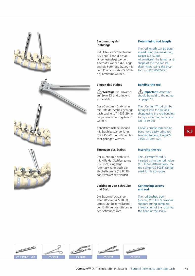
Bestimmung der Stablänge
Mit Hilfe des Größentasters (CS 5788) kann die Stablänge festgelegt werden.Alternativ können die Länge und die Form des Stabes mit dem Phantomstab (CS 8032XX) bestimmt werden.
Biegen des Stabes
! Wichtig: Die Hinweise auf Seite 23 sind dringend zu beachten.
Der uCentumTM Stab kann mit Hilfe der Stabbiegezange nach Lepine (UT 163929) in die passende Form gebracht werden.
Kobaltchromstäbe können mit Stabbiegezange, lang (CS 715801 und 02) einfacher gebogen werden.
Einsetzen des Stabes
Der uCentumTM Stab wird mit Hilfe der Stabfasszange (CS 3024) eingelegt. Alternativ kann auch die Stabhaltezange (CS 8038) dafür verwendet werden.
Verbinden von Schraube und Stab
Die Stabeindrückzange, offen (Rocker) (CS 3837) unterstützt beim vollständigen Einführen des Stabes in den Schraubenkopf.
Determining rod length
The rod length can be determined using the measuring caliper (CS 5788). Alternatively, the length and shape of the rod can be determined using the phantom rod (CS 8032XX).
Bending the rod
! Important: Attention should be paid to the notes on page 23.
The uCentumTM rod can be brought into the suitable shape using the rod bending forceps according to Lepine (UT 163929).
Cobalt chrome rods can be bent more easily using rod bending forceps, long (CS 715801 und 02).
Inserting the rod
The uCentumTM rod is inserted using the rod holder (CS 3024). Alternatively, the rod clamp (CS 8038) can be used for this purpose.
Connecting screws and rod
The rod pusher, open (Rocker) (CS 3837) provides support during complete introduction of the rod into the head of the screw.
CS 8038 CS 3837CS 3024 CS 3836CS 7158-01, -02
uCentumTM OP-Technik, offener Zugang l Surgical technique, open approach44
Operationstechnik l Surgical technique
6.3
CS 7144 CS 3846
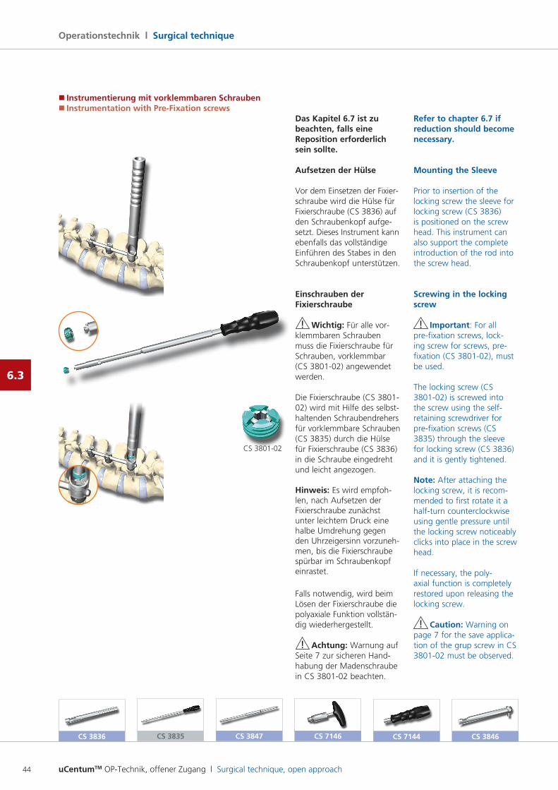
Das Kapitel 6.7 ist zu beachten, falls eine Reposition erforderlich sein sollte.
Aufsetzen der Hülse
Vor dem Einsetzen der Fixier schraube wird die Hülse für Fixierschraube (CS 3836) auf den Schraubenkopf aufgesetzt. Dieses Instrument kann ebenfalls das vollständige Einführen des Stabes in den Schraubenkopf unterstützen.
Einschrauben der Fixierschraube
! Wichtig: Für alle vorklemmbaren Schrauben muss die Fixierschraube für Schrauben, vorklemmbar (CS 380102) angewendet werden.
Die Fixierschraube (CS 380102) wird mit Hilfe des selbsthaltenden Schraubendrehers für vorklemmbare Schrauben (CS 3835) durch die Hülse für Fixierschraube (CS 3836) in die Schraube eingedreht und leicht angezogen.
Hinweis: Es wird empfohlen, nach Aufsetzen der Fixierschraube zunächst unter leichtem Druck eine halbe Umdrehung gegen den Uhrzeigersinn vorzunehmen, bis die Fixierschraube spürbar im Schraubenkopf einrastet.
Falls notwendig, wird beim Lösen der Fixierschraube die polyaxiale Funktion vollständig wiederhergestellt.
! Achtung: Warnung auf Seite 7 zur sicheren Hand habung der Madenschraube in CS 380102 beachten.
Refer to chapter 6.7 if reduction should become necessary.
Mounting the Sleeve
Prior to insertion of the locking screw the sleeve for locking screw (CS 3836) is positioned on the screw head. This instrument can also support the complete introduction of the rod into the screw head.
Screwing in the locking screw
! Important: For all prefixation screws, locking screw for screws, prefixation (CS 380102), must be used.
The locking screw (CS 380102) is screwed into the screw using the selfretaining screwdriver for prefixation screws (CS 3835) through the sleeve for locking screw (CS 3836) and it is gently tightened.
Note: After attaching the locking screw, it is recommended to first rotate it a halfturn counterclockwise using gentle pressure until the locking screw noticeably clicks into place in the screw head.
If necessary, the polyaxial function is completely restored upon releasing the locking screw.
! Caution: Warning on page 7 for the save application of the grup screw in CS 380102 must be observed.
CS 3835 CS 7146CS 3847CS 3836
� Instrumentierung mit vorklemmbaren Schrauben� Instrumentation with Pre-Fixation screws
CS 380102
uCentumTM OP-Technik, offener Zugang l Surgical technique, open approach 45
6.3
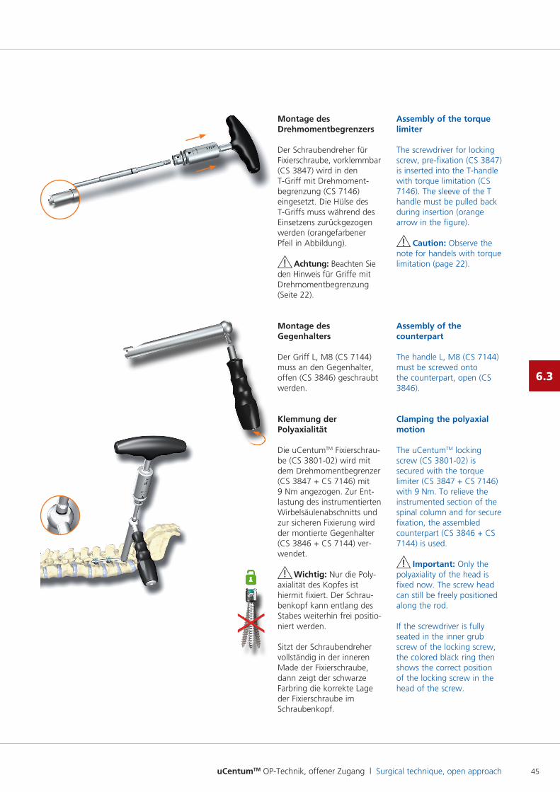
Montage des Drehmomentbegrenzers
Der Schraubendreher für Fixierschraube, vorklemmbar (CS 3847) wird in den TGriff mit Drehmomentbegrenzung (CS 7146) eingesetzt. Die Hülse des TGriffs muss während des Einsetzens zurückgezogen werden (orangefarbener Pfeil in Abbildung).
! Achtung: Beachten Sie den Hinweis für Griffe mit Drehmomentbegrenzung (Seite 22).
Montage des Gegenhalters
Der Griff L, M8 (CS 7144) muss an den Gegenhalter, offen (CS 3846) geschraubt werden.
Klemmung der Polyaxialität
Die uCentumTM Fixierschraube (CS 380102) wird mit dem Drehmomentbegrenzer (CS 3847 + CS 7146) mit 9 Nm angezogen. Zur Entlastung des instrumentierten Wirbelsäulenabschnitts und zur sicheren Fixierung wird der montierte Gegenhalter (CS 3846 + CS 7144) verwendet.
! Wichtig: Nur die Poly axialität des Kopfes ist hiermit fixiert. Der Schraubenkopf kann entlang des Stabes weiterhin frei positioniert werden.
Sitzt der Schraubendreher vollständig in der inneren Made der Fixierschraube, dann zeigt der schwarze Farbring die korrekte Lage der Fixierschraube im Schraubenkopf.
Assembly of the torque limiter
The screwdriver for locking screw, prefixation (CS 3847) is inserted into the Thandle with torque limitation (CS 7146). The sleeve of the T handle must be pulled back during insertion (orange arrow in the figure).
! Caution: Observe the note for handels with torque limitation (page 22).
Assembly of the counterpart
The handle L, M8 (CS 7144) must be screwed onto the counterpart, open (CS 3846).
Clamping the polyaxial motion
The uCentumTM locking screw (CS 380102) is secured with the torque limiter (CS 3847 + CS 7146) with 9 Nm. To relieve the instrumented section of the spinal column and for secure fixation, the assembled counterpart (CS 3846 + CS 7144) is used.
! Important: Only the polyaxiality of the head is fixed now. The screw head can still be freely positioned along the rod.
If the screwdriver is fully seated in the inner grub screw of the locking screw, the colored black ring then shows the correct position of the locking screw in the head of the screw.
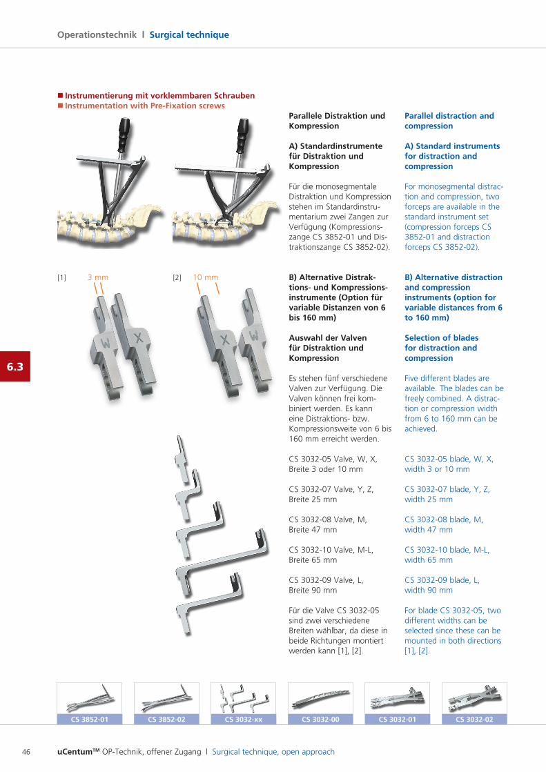
uCentumTM OP-Technik, offener Zugang l Surgical technique, open approach46
Operationstechnik l Surgical technique
6.3
CS 3032-02CS 3032-00 CS 3032-01CS 3852-02
Parallele Distraktion und Kompression
A) Standardinstrumente für Distraktion und Kompression
Für die monosegmentale Distraktion und Kompression stehen im Standardinstrumentarium zwei Zangen zur Verfügung (Kompressions zange CS 385201 und Distraktionszange CS 385202).
B) Alternative Distrak- tions- und Kompressions-instrumente (Option für variable Distanzen von 6 bis 160 mm)
Auswahl der Valven für Distraktion und Kompression
Es stehen fünf verschiedene Valven zur Verfügung. Die Valven können frei kombiniert werden. Es kann eine Distraktions bzw. Kompressionsweite von 6 bis 160 mm erreicht werden.
CS 303205 Valve, W, X, Breite 3 oder 10 mm
CS 303207 Valve, Y, Z, Breite 25 mm
CS 303208 Valve, M, Breite 47 mm
CS 303210 Valve, ML, Breite 65 mm
CS 303209 Valve, L, Breite 90 mm
Für die Valve CS 303205 sind zwei verschiedene Breiten wählbar, da diese in beide Richtungen montiert werden kann [1], [2].
Parallel distraction and compression
A) Standard instruments for distraction and compression
For monosegmental distraction and compression, two forceps are available in the standard instrument set (compression forceps CS 385201 and distraction forceps CS 385202).
B) Alternative distraction and compression instruments (option for variable distances from 6 to 160 mm)
Selection of blades for distraction and compression
Five different blades are available. The blades can be freely combined. A distraction or compression width from 6 to 160 mm can be achieved.
CS 303205 blade, W, X, width 3 or 10 mm
CS 303207 blade, Y, Z, width 25 mm
CS 303208 blade, M, width 47 mm
CS 303210 blade, ML, width 65 mm
CS 303209 blade, L, width 90 mm
For blade CS 303205, two different widths can be selected since these can be mounted in both directions [1], [2].
[1] [2]3 mm 10 mm
� Instrumentierung mit vorklemmbaren Schrauben� Instrumentation with Pre-Fixation screws
CS 3032-xxCS 3852-01
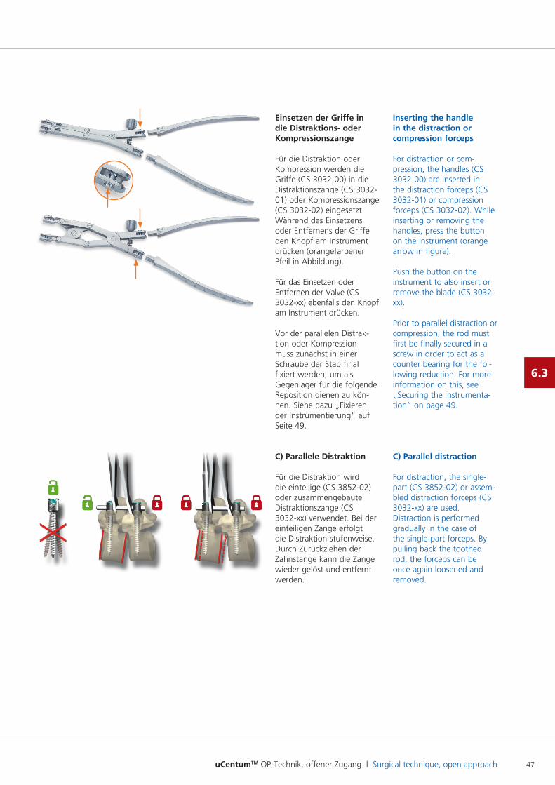
uCentumTM OP-Technik, offener Zugang l Surgical technique, open approach 47
6.3
Einsetzen der Griffe in die Distraktions- oder Kompressionszange
Für die Distraktion oder Kompression werden die Griffe (CS 303200) in die Distraktionszange (CS 303201) oder Kompressionszange (CS 303202) eingesetzt. Während des Einsetzens oder Entfernens der Griffe den Knopf am Instrument drücken (orangefarbener Pfeil in Abbildung).
Für das Einsetzen oder Entfernen der Valve (CS 3032xx) ebenfalls den Knopf am Instrument drücken.
Vor der parallelen Distraktion oder Kompression muss zunächst in einer Schraube der Stab final fixiert werden, um als Gegenlager für die folgende Reposition dienen zu können. Siehe dazu „Fixieren der Instrumentierung“ auf Seite 49.
C) Parallele Distraktion
Für die Distraktion wird die einteilige (CS 385202) oder zusammengebaute Distraktionszange (CS 3032xx) verwendet. Bei der einteiligen Zange erfolgt die Distraktion stufenweise. Durch Zurückziehen der Zahnstange kann die Zange wieder gelöst und entfernt werden.
Inserting the handle in the distraction or compression forceps
For distraction or compression, the handles (CS 303200) are inserted in the distraction forceps (CS 303201) or compression forceps (CS 303202). While inserting or removing the handles, press the button on the instrument (orange arrow in figure).
Push the button on the instrument to also insert or remove the blade (CS 3032xx).
Prior to parallel distraction or compression, the rod must first be finally secured in a screw in order to act as a counter bearing for the following reduction. For more information on this, see „Securing the instrumentation“ on page 49.
C) Parallel distraction
For distraction, the singlepart (CS 385202) or assembled distraction forceps (CS 3032xx) are used. Distraction is performed gradually in the case of the singlepart forceps. By pulling back the toothed rod, the forceps can be once again loosened and removed.
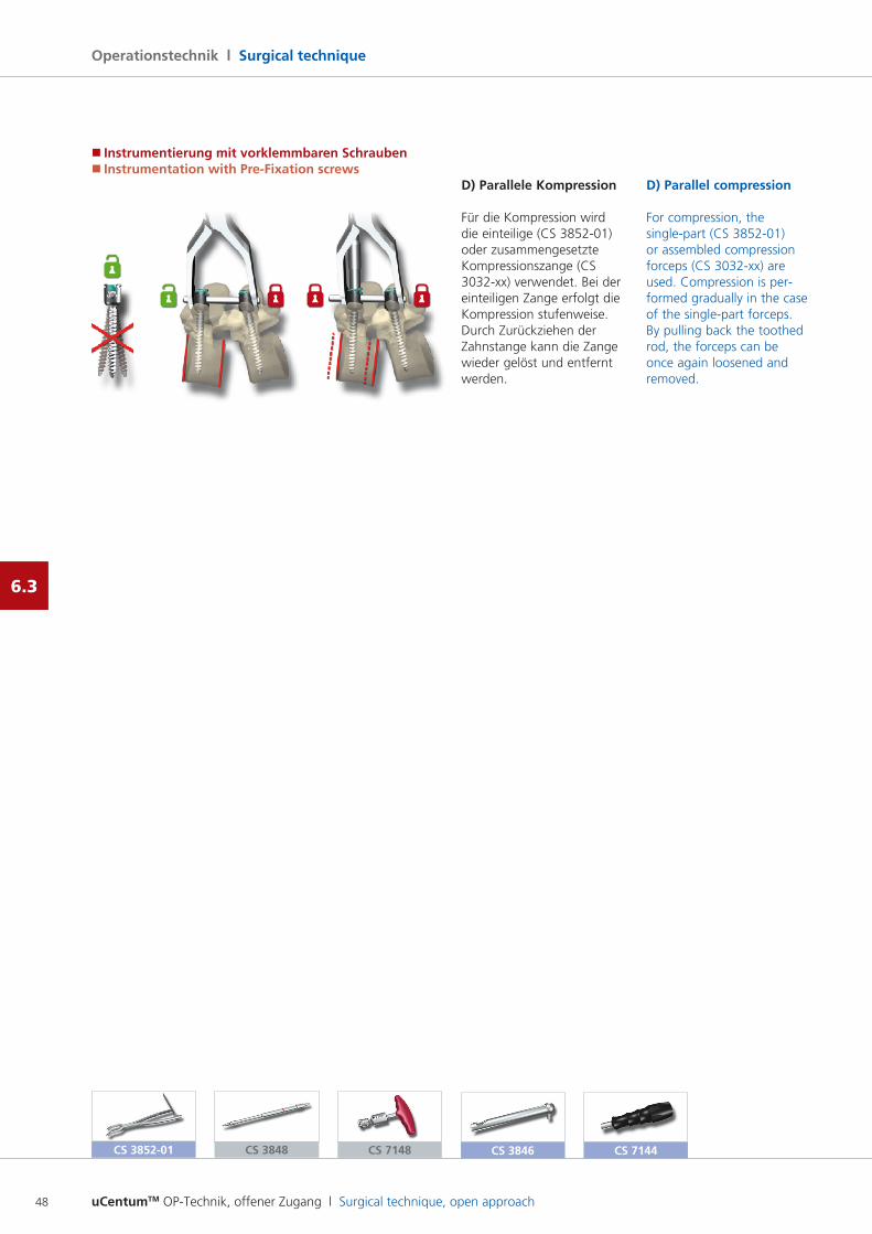
uCentumTM OP-Technik, offener Zugang l Surgical technique, open approach48
Operationstechnik l Surgical technique
6.3
� Instrumentierung mit vorklemmbaren Schrauben� Instrumentation with Pre-Fixation screws
D) Parallele Kompression
Für die Kompression wird die einteilige (CS 385201) oder zusammengesetzte Kompressionszange (CS 3032xx) verwendet. Bei der einteiligen Zange erfolgt die Kompression stufenweise. Durch Zurückziehen der Zahnstange kann die Zange wieder gelöst und entfernt werden.
D) Parallel compression
For compression, the singlepart (CS 385201) or assembled compression forceps (CS 3032xx) are used. Compression is performed gradually in the case of the singlepart forceps. By pulling back the toothed rod, the forceps can be once again loosened and removed.
CS 3852-01 CS 3848 CS 7148 CS 3846 CS 7144
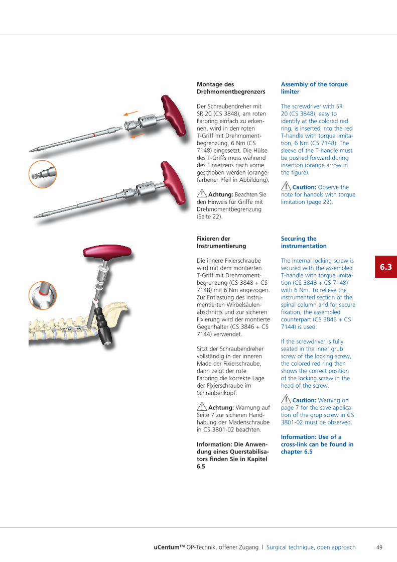
uCentumTM OP-Technik, offener Zugang l Surgical technique, open approach 49
6.3
Montage des Drehmomentbegrenzers
Der Schraubendreher mit SR 20 (CS 3848), am roten Farbring einfach zu erken nen, wird in den roten TGriff mit Drehmomentbegrenzung, 6 Nm (CS 7148) eingesetzt. Die Hülse des TGriffs muss während des Einsetzens nach vorne geschoben werden (orangefarbener Pfeil in Abbildung).
! Achtung: Beachten Sie den Hinweis für Griffe mit Drehmomentbegrenzung (Seite 22).
Fixieren der Instrumentierung
Die innere Fixierschraube wird mit dem montierten TGriff mit Drehmomentbegrenzung (CS 3848 + CS 7148) mit 6 Nm angezogen. Zur Entlastung des instru mentierten Wirbelsäulenabschnitts und zur sicheren Fixierung wird der montierte Gegenhalter (CS 3846 + CS 7144) verwendet.
Sitzt der Schraubendreher vollständig in der inneren Made der Fixierschraube, dann zeigt der rote Farbring die korrekte Lage der Fixierschraube im Schraubenkopf.
! Achtung: Warnung auf Seite 7 zur sicheren Hand habung der Madenschraube in CS 380102 beachten.
Information: Die Anwen- dung eines Querstabilisa-tors finden Sie in Kapitel 6.5
Assembly of the torque limiter
The screwdriver with SR 20 (CS 3848), easy to identify at the colored red ring, is inserted into the red Thandle with torque limitation, 6 Nm (CS 7148). The sleeve of the Thandle must be pushed forward during insertion (orange arrow in the figure).
! Caution: Observe the note for handels with torque limitation (page 22).
Securing the instrumentation
The internal locking screw is secured with the assembled Thandle with torque limitation (CS 3848 + CS 7148) with 6 Nm. To relieve the instrumented section of the spinal column and for secure fixation, the assembled counterpart (CS 3846 + CS 7144) is used.
If the screwdriver is fully seated in the inner grub screw of the locking screw, the colored red ring then shows the correct position of the locking screw in the head of the screw.
! Caution: Warning on page 7 for the save application of the grup screw in CS 380102 must be observed.
Information: Use of a cross-link can be found in chapter 6.5
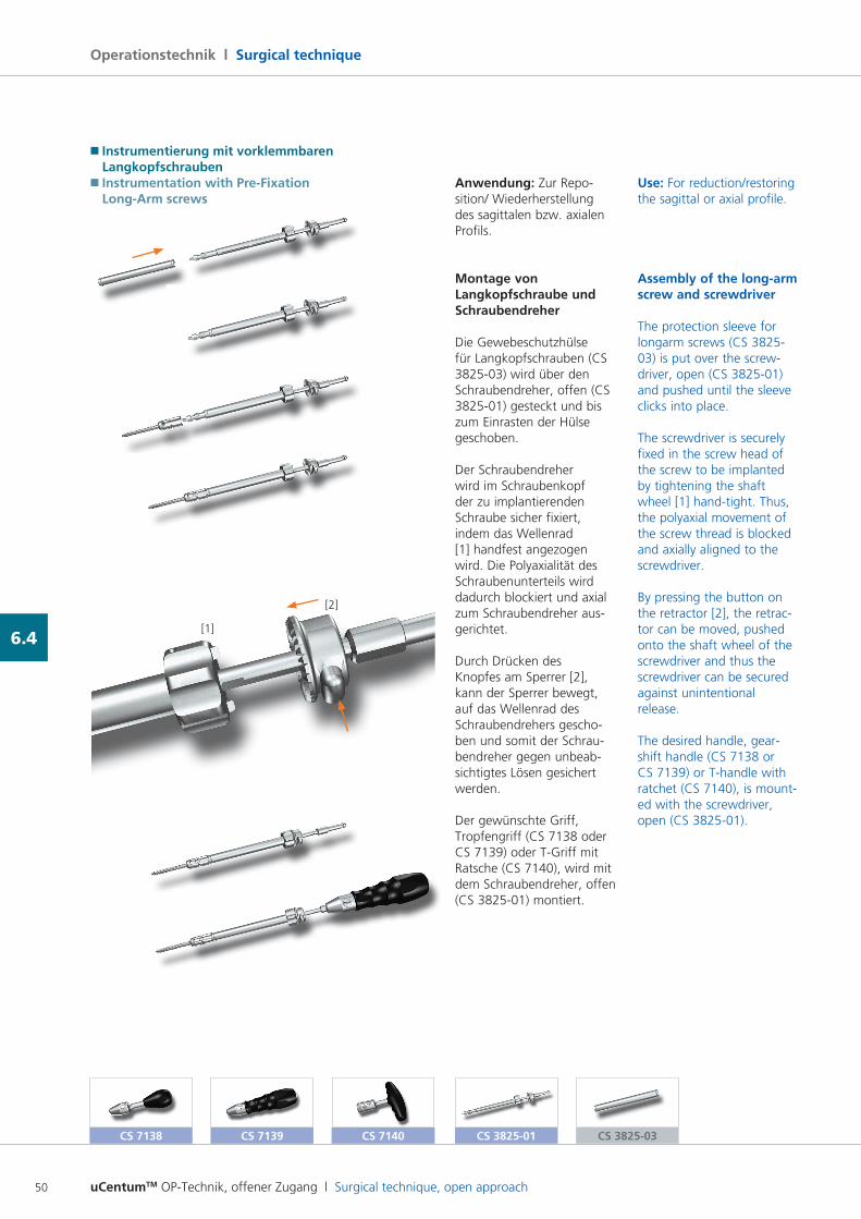
uCentumTM OP-Technik, offener Zugang l Surgical technique, open approach50
Operationstechnik l Surgical technique
6.4
Anwendung: Zur Reposition/ Wiederherstellung des sagittalen bzw. axialen Profils.
Montage von Langkopfschraube und Schraubendreher
Die Gewebeschutzhülse für Langkopfschrauben (CS 382503) wird über den Schraubendreher, offen (CS 382501) gesteckt und bis zum Einrasten der Hülse geschoben.
Der Schraubendreher wird im Schraubenkopf der zu implantierenden Schraube sicher fixiert, indem das Wellenrad [1] handfest angezogen wird. Die Polyaxialität des Schraubenunterteils wird dadurch blockiert und axial zum Schraubendreher ausgerichtet.
Durch Drücken des Knopfes am Sperrer [2], kann der Sperrer bewegt, auf das Wellenrad des Schraubendrehers geschoben und somit der Schraubendreher gegen unbeabsichtigtes Lösen gesichert werden.
Der gewünschte Griff, Tropfengriff (CS 7138 oder CS 7139) oder TGriff mit Ratsche (CS 7140), wird mit dem Schraubendreher, offen (CS 382501) montiert.
Use: For reduction/restoring the sagittal or axial profile.
Assembly of the long-arm screw and screwdriver
The protection sleeve for longarm screws (CS 382503) is put over the screwdriver, open (CS 382501) and pushed until the sleeve clicks into place.
The screwdriver is securely fixed in the screw head of the screw to be implanted by tightening the shaft wheel [1] handtight. Thus, the polyaxial movement of the screw thread is blocked and axially aligned to the screwdriver.
By pressing the button on the retractor [2], the retractor can be moved, pushed onto the shaft wheel of the screwdriver and thus the screwdriver can be secured against unintentional release.
The desired handle, gearshift handle (CS 7138 or CS 7139) or Thandle with ratchet (CS 7140), is mounted with the screwdriver, open (CS 382501).
CS 7138 CS 7139 CS 7140 CS 3825-01 CS 3825-03
� Instrumentierung mit vorklemmbaren Langkopfschrauben� Instrumentation with Pre-Fixation Long-Arm screws
[1]
[2]
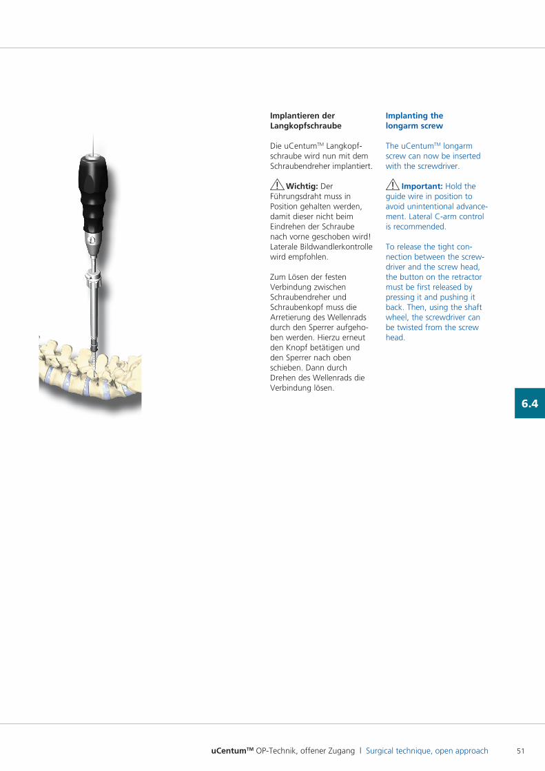
uCentumTM OP-Technik, offener Zugang l Surgical technique, open approach 51
6.4
Implantieren der Langkopfschraube
Die uCentumTM Langkopfschraube wird nun mit dem Schraubendreher implantiert.
! Wichtig: Der Führungsdraht muss in Position gehalten werden, damit dieser nicht beim Eindrehen der Schraube nach vorne geschoben wird! Laterale Bildwandlerkontrolle wird empfohlen.
Zum Lösen der festen Verbindung zwischen Schraubendreher und Schraubenkopf muss die Arretierung des Wellenrads durch den Sperrer aufgehoben werden. Hierzu erneut den Knopf betätigen und den Sperrer nach oben schieben. Dann durch Drehen des Wellenrads die Verbindung lösen.
Implanting the longarm screw
The uCentumTM longarm screw can now be inserted with the screwdriver.
! Important: Hold the guide wire in position to avoid unintentional advancement. Lateral Carm control is recommended.
To release the tight connection between the screwdriver and the screw head, the button on the retractor must be first released by pressing it and pushing it back. Then, using the shaft wheel, the screwdriver can be twisted from the screw head.
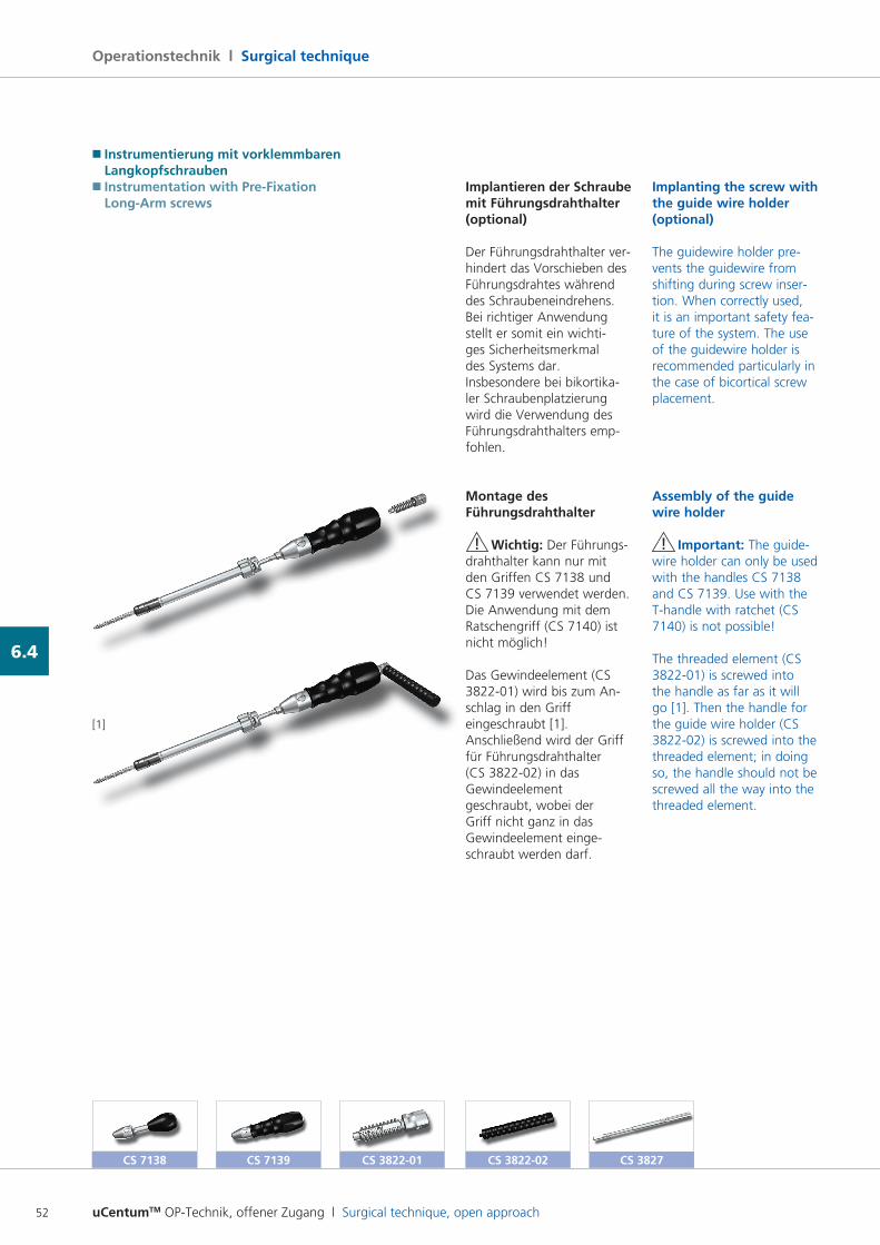
uCentumTM OP-Technik, offener Zugang l Surgical technique, open approach52
Operationstechnik l Surgical technique
6.4
Implantieren der Schraube mit Führungsdrahthalter (optional)
Der Führungsdrahthalter verhindert das Vorschieben des Führungsdrahtes während des Schraubeneindrehens. Bei richtiger Anwendung stellt er somit ein wichtiges Sicherheitsmerkmal des Systems dar. Insbesondere bei bikortikaler Schraubenplatzierung wird die Verwendung des Führungsdrahthalters empfohlen.
Montage des Führungsdrahthalter
! Wichtig: Der Führungsdrahthalter kann nur mit den Griffen CS 7138 und CS 7139 verwendet werden. Die Anwendung mit dem Ratschengriff (CS 7140) ist nicht möglich!
Das Gewindeelement (CS 382201) wird bis zum An schlag in den Griff eingeschraubt [1]. Anschließend wird der Griff für Führungsdrahthalter (CS 382202) in das Gewindeelement geschraubt, wobei der Griff nicht ganz in das Gewindeelement eingeschraubt werden darf.
Implanting the screw with the guide wire holder (optional)
The guidewire holder prevents the guidewire from shifting during screw insertion. When correctly used, it is an important safety feature of the system. The use of the guidewire holder is recommended particularly in the case of bicortical screw placement.
Assembly of the guide wire holder
! Important: The guidewire holder can only be used with the handles CS 7138 and CS 7139. Use with the Thandle with ratchet (CS 7140) is not possible!
The threaded element (CS 382201) is screwed into the handle as far as it will go [1]. Then the handle for the guide wire holder (CS 382202) is screwed into the threaded element; in doing so, the handle should not be screwed all the way into the threaded element.
CS 7138 CS 7139 CS 3822-01 CS 3822-02
[1]
CS 3827
� Instrumentierung mit vorklemmbaren Langkopfschrauben� Instrumentation with Pre-Fixation Long-Arm screws
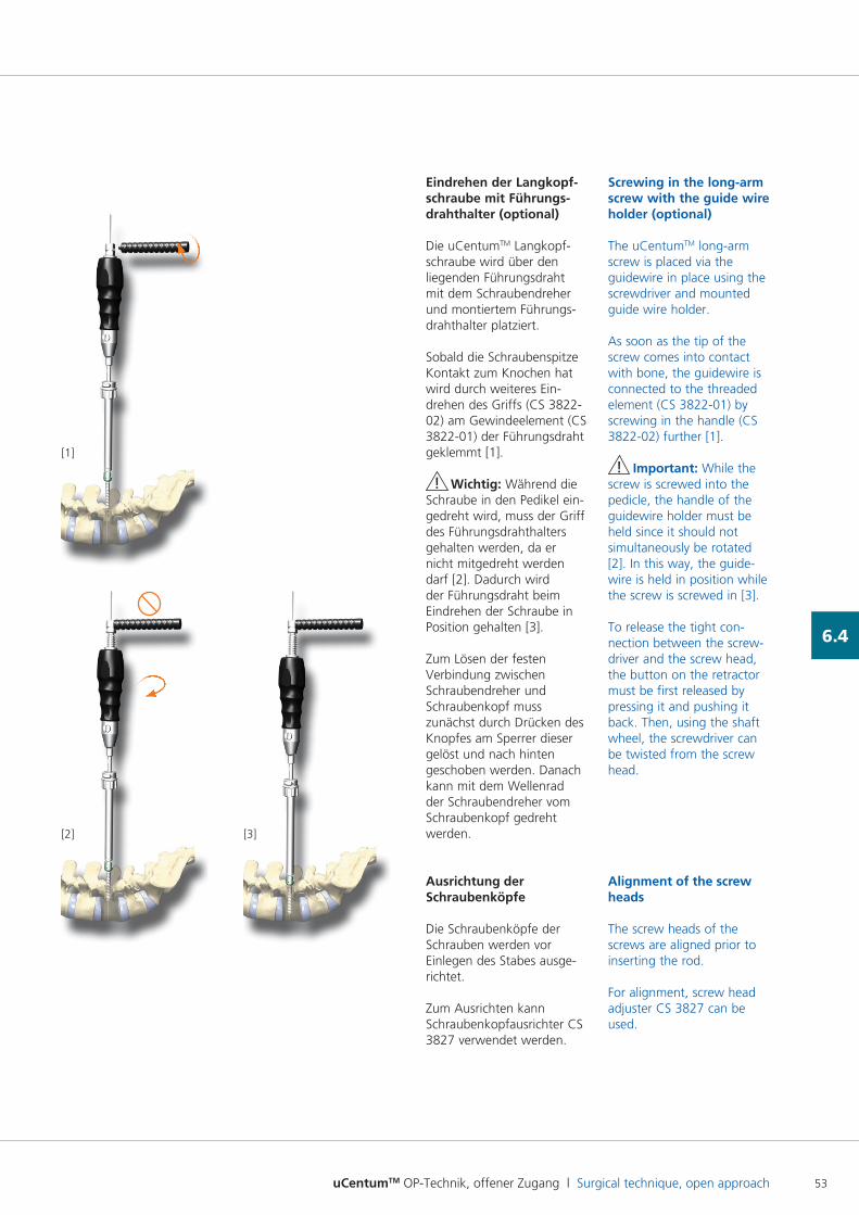
uCentumTM OP-Technik, offener Zugang l Surgical technique, open approach 53
6.4
Eindrehen der Langkopf- schraube mit Führungs-drahthalter (optional)
Die uCentumTM Langkopfschraube wird über den liegenden Führungsdraht mit dem Schraubendreher und montiertem Führungsdrahthalter platziert.
Sobald die Schraubenspitze Kontakt zum Knochen hat wird durch weiteres Eindrehen des Griffs (CS 382202) am Gewindeelement (CS 382201) der Führungsdraht geklemmt [1].
! Wichtig: Während die Schraube in den Pedikel eingedreht wird, muss der Griff des Führungsdrahthalters gehalten werden, da er nicht mitgedreht werden darf [2]. Dadurch wird der Führungsdraht beim Eindrehen der Schraube in Position gehalten [3].
Zum Lösen der festen Verbindung zwischen Schraubendreher und Schraubenkopf muss zunächst durch Drücken des Knopfes am Sperrer dieser gelöst und nach hinten geschoben werden. Danach kann mit dem Wellenrad der Schraubendreher vom Schraubenkopf gedreht werden.
Ausrichtung der Schraubenköpfe
Die Schraubenköpfe der Schrauben werden vor Einlegen des Stabes ausgerichtet.
Zum Ausrichten kann Schraubenkopfausrichter CS 3827 verwendet werden.
Screwing in the long-arm screw with the guide wire holder (optional)
The uCentumTM longarm screw is placed via the guidewire in place using the screwdriver and mounted guide wire holder.
As soon as the tip of the screw comes into contact with bone, the guidewire is connected to the threaded element (CS 382201) by screwing in the handle (CS 382202) further [1].
! Important: While the screw is screwed into the pedicle, the handle of the guidewire holder must be held since it should not simultaneously be rotated [2]. In this way, the guidewire is held in position while the screw is screwed in [3].
To release the tight connection between the screwdriver and the screw head, the button on the retractor must be first released by pressing it and pushing it back. Then, using the shaft wheel, the screwdriver can be twisted from the screw head.
Alignment of the screw heads
The screw heads of the screws are aligned prior to inserting the rod.
For alignment, screw head adjuster CS 3827 can be used.
[1]
[2] [3]
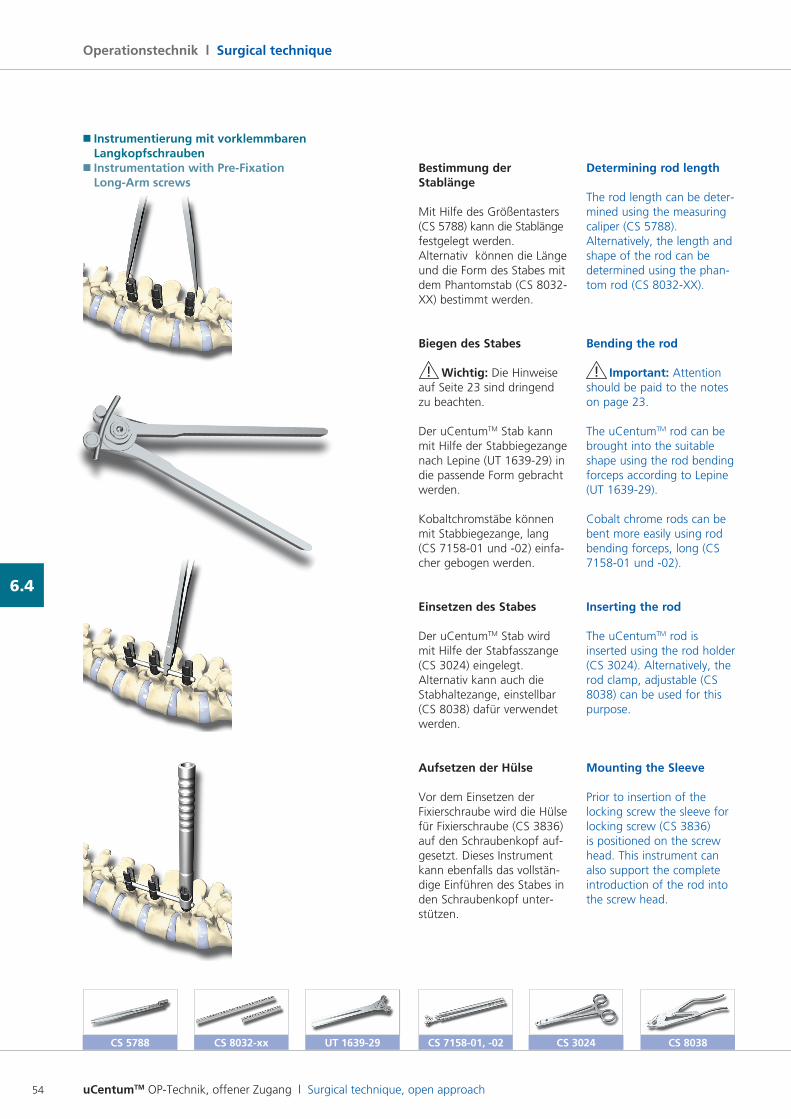
uCentumTM OP-Technik, offener Zugang l Surgical technique, open approach54
Operationstechnik l Surgical technique
6.4
Bestimmung der Stablänge
Mit Hilfe des Größentasters (CS 5788) kann die Stablänge festgelegt werden. Alternativ können die Länge und die Form des Stabes mit dem Phantomstab (CS 8032XX) bestimmt werden.
Biegen des Stabes
! Wichtig: Die Hinweise auf Seite 23 sind dringend zu beachten.
Der uCentumTM Stab kann mit Hilfe der Stabbiegezange nach Lepine (UT 163929) in die passende Form gebracht werden.
Kobaltchromstäbe können mit Stabbiegezange, lang (CS 715801 und 02) einfacher gebogen werden.
Einsetzen des Stabes
Der uCentumTM Stab wird mit Hilfe der Stabfasszange (CS 3024) eingelegt. Alternativ kann auch die Stabhaltezange, einstellbar (CS 8038) dafür verwendet werden.
Aufsetzen der Hülse
Vor dem Einsetzen der Fixierschraube wird die Hülse für Fixierschraube (CS 3836) auf den Schraubenkopf aufgesetzt. Dieses Instrument kann ebenfalls das vollständige Einführen des Stabes in den Schraubenkopf unterstützen.
Determining rod length
The rod length can be determined using the measuring caliper (CS 5788). Alternatively, the length and shape of the rod can be determined using the phantom rod (CS 8032XX).
Bending the rod
! Important: Attention should be paid to the notes on page 23.
The uCentumTM rod can be brought into the suitable shape using the rod bending forceps according to Lepine (UT 163929).
Cobalt chrome rods can be bent more easily using rod bending forceps, long (CS 715801 und 02).
Inserting the rod
The uCentumTM rod is inserted using the rod holder (CS 3024). Alternatively, the rod clamp, adjustable (CS 8038) can be used for this purpose.
Mounting the Sleeve
Prior to insertion of the locking screw the sleeve for locking screw (CS 3836) is positioned on the screw head. This instrument can also support the complete introduction of the rod into the screw head.
CS 5788 CS 8032-xx UT 1639-29 CS 3024 CS 8038
� Instrumentierung mit vorklemmbaren Langkopfschrauben� Instrumentation with Pre-Fixation Long-Arm screws
CS 7158-01, -02
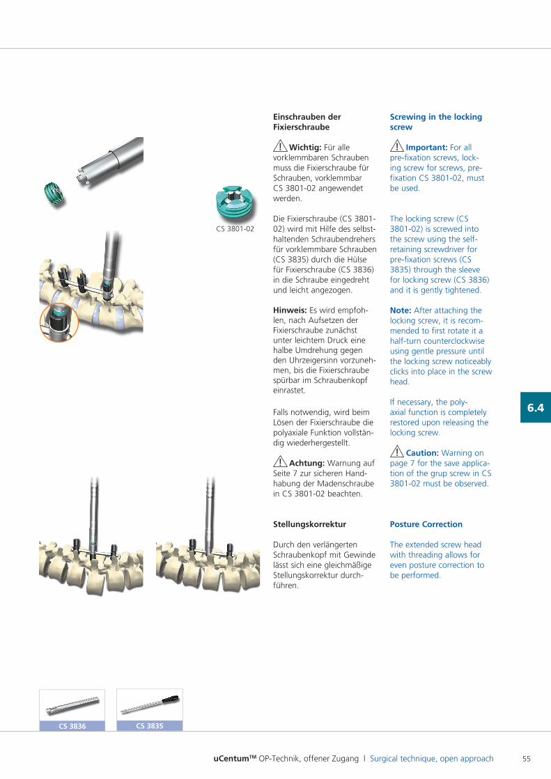
uCentumTM OP-Technik, offener Zugang l Surgical technique, open approach 55
6.4
CS 3836
Einschrauben der Fixierschraube
! Wichtig: Für alle vorklemmbaren Schrauben muss die Fixierschraube für Schrauben, vorklemmbar CS 380102 angewendet werden.
Die Fixierschraube (CS 380102) wird mit Hilfe des selbsthaltenden Schraubendrehers für vorklemmbare Schrauben (CS 3835) durch die Hülse für Fixierschraube (CS 3836) in die Schraube eingedreht und leicht angezogen.
Hinweis: Es wird empfohlen, nach Aufsetzen der Fixierschraube zunächst unter leichtem Druck eine halbe Umdrehung gegen den Uhrzeigersinn vorzunehmen, bis die Fixierschraube spürbar im Schraubenkopf einrastet.
Falls notwendig, wird beim Lösen der Fixierschraube die polyaxiale Funktion vollständig wiederhergestellt.
! Achtung: Warnung auf Seite 7 zur sicheren Hand habung der Madenschraube in CS 380102 beachten.
Stellungskorrektur
Durch den verlängerten Schraubenkopf mit Gewinde lässt sich eine gleichmäßige Stellungskorrektur durchführen.
CS 380102
Screwing in the locking screw
! Important: For all prefixation screws, locking screw for screws, prefixation CS 380102, must be used.
The locking screw (CS 380102) is screwed into the screw using the selfretaining screwdriver for prefixation screws (CS 3835) through the sleeve for locking screw (CS 3836) and it is gently tightened.
Note: After attaching the locking screw, it is recommended to first rotate it a halfturn counterclockwise using gentle pressure until the locking screw noticeably clicks into place in the screw head.
If necessary, the polyaxial function is completely restored upon releasing the locking screw.
! Caution: Warning on page 7 for the save application of the grup screw in CS 380102 must be observed.
Posture Correction
The extended screw head with threading allows for even posture correction to be performed.
CS 3835
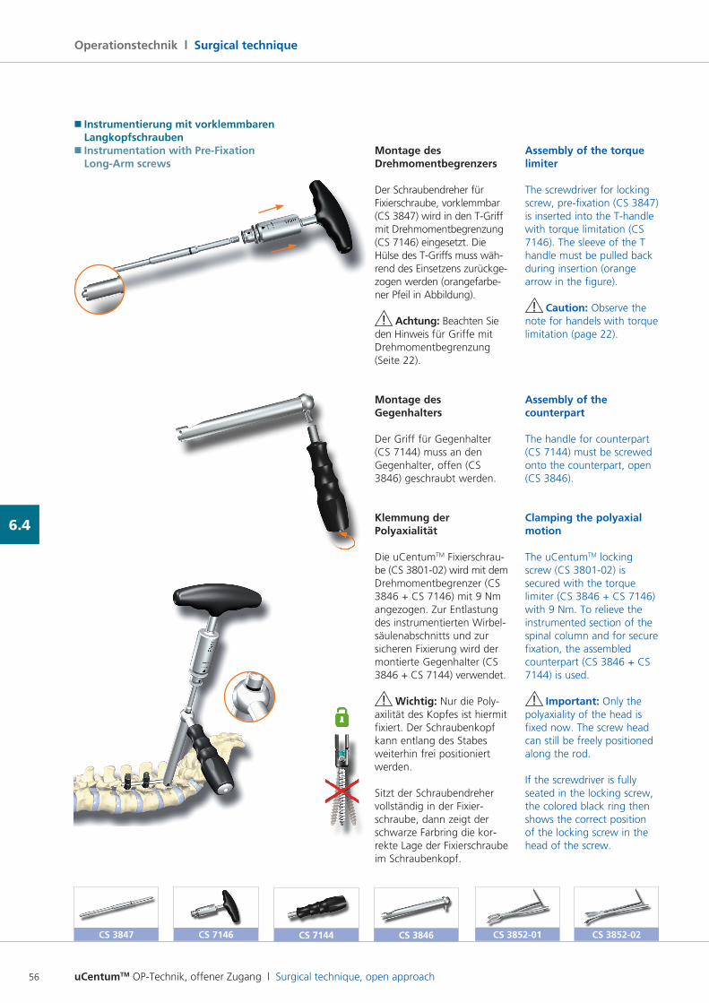
uCentumTM OP-Technik, offener Zugang l Surgical technique, open approach56
Operationstechnik l Surgical technique
6.4
Montage des Drehmomentbegrenzers
Der Schraubendreher für Fixierschraube, vorklemmbar (CS 3847) wird in den TGriff mit Drehmomentbegrenzung (CS 7146) eingesetzt. Die Hülse des TGriffs muss während des Einsetzens zurückgezogen werden (orangefarbener Pfeil in Abbildung).
! Achtung: Beachten Sie den Hinweis für Griffe mit Drehmomentbegrenzung (Seite 22).
Montage des Gegenhalters
Der Griff für Gegenhalter (CS 7144) muss an den Gegenhalter, offen (CS 3846) geschraubt werden.
Klemmung der Polyaxialität
Die uCentumTM Fixierschraube (CS 380102) wird mit dem Drehmomentbegrenzer (CS 3846 + CS 7146) mit 9 Nm angezogen. Zur Entlastung des instrumentierten Wirbelsäulenabschnitts und zur sicheren Fixierung wird der montierte Gegenhalter (CS 3846 + CS 7144) verwendet.
! Wichtig: Nur die Polyaxilität des Kopfes ist hiermit fixiert. Der Schraubenkopf kann entlang des Stabes weiterhin frei positioniert werden.
Sitzt der Schraubendreher vollständig in der Fixierschraube, dann zeigt der schwarze Farbring die korrekte Lage der Fixierschraube im Schraubenkopf.
Assembly of the torque limiter
The screwdriver for locking screw, prefixation (CS 3847) is inserted into the Thandle with torque limitation (CS 7146). The sleeve of the T handle must be pulled back during insertion (orange arrow in the figure).
! Caution: Observe the note for handels with torque limitation (page 22).
Assembly of the counterpart
The handle for counterpart (CS 7144) must be screwed onto the counterpart, open (CS 3846).
Clamping the polyaxial motion
The uCentumTM locking screw (CS 380102) is secured with the torque limiter (CS 3846 + CS 7146) with 9 Nm. To relieve the instrumented section of the spinal column and for secure fixation, the assembled counterpart (CS 3846 + CS 7144) is used.
! Important: Only the polyaxiality of the head is fixed now. The screw head can still be freely positioned along the rod.
If the screwdriver is fully seated in the locking screw, the colored black ring then shows the correct position of the locking screw in the head of the screw.
CS 7146CS 3847 CS 7144 CS 3846 CS 3852-01 CS 3852-02
� Instrumentierung mit vorklemmbaren Langkopfschrauben� Instrumentation with Pre-Fixation Long-Arm screws
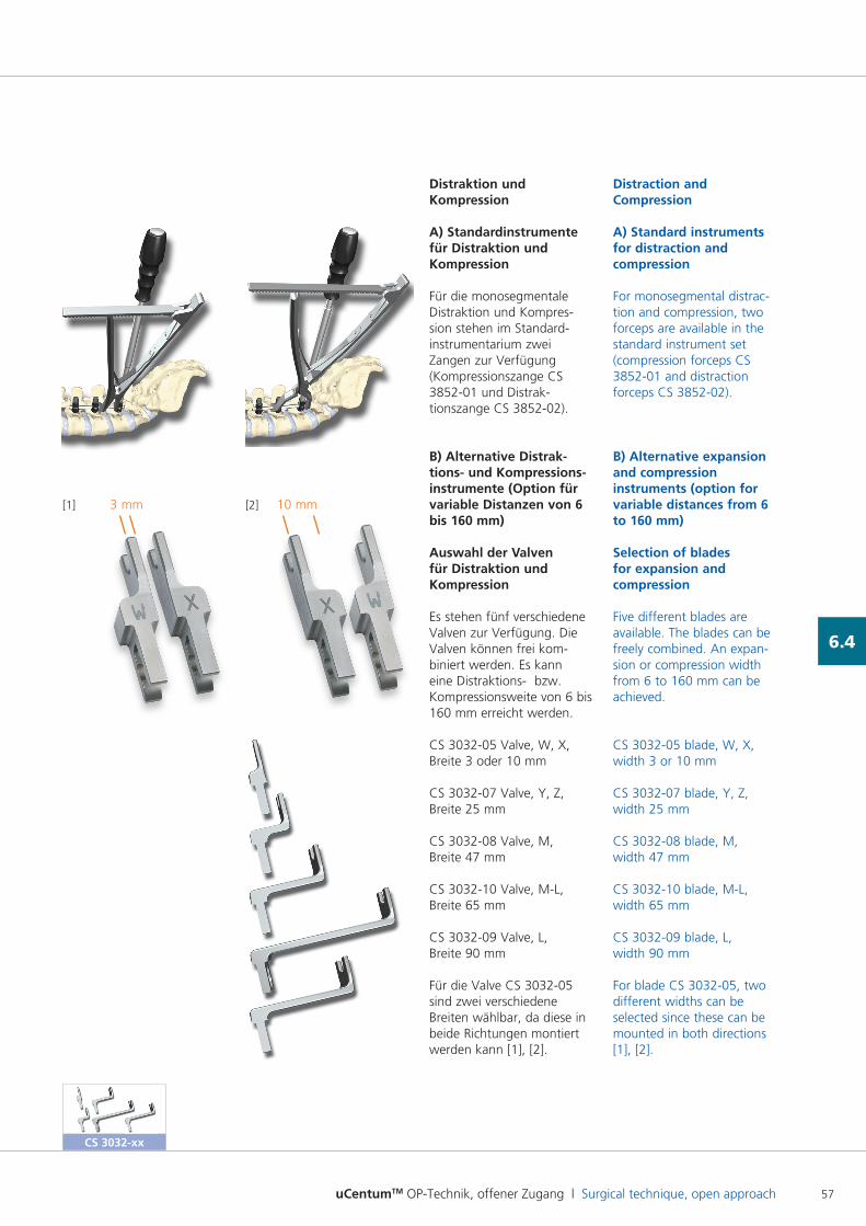
uCentumTM OP-Technik, offener Zugang l Surgical technique, open approach 57
6.4
Distraktion und Kompression
A) Standardinstrumente für Distraktion und Kompression
Für die monosegmentale Distraktion und Kompres sion stehen im Standardinstrumentarium zwei Zangen zur Verfügung (Kompressionszange CS 385201 und Distraktionszange CS 385202).
B) Alternative Distrak- tions- und Kompressions-instrumente (Option für variable Distanzen von 6 bis 160 mm)
Auswahl der Valven für Distraktion und Kompression
Es stehen fünf verschiedene Valven zur Verfügung. Die Valven können frei kombiniert werden. Es kann eine Distraktions bzw. Kompressionsweite von 6 bis 160 mm erreicht werden.
CS 303205 Valve, W, X, Breite 3 oder 10 mm
CS 303207 Valve, Y, Z, Breite 25 mm
CS 303208 Valve, M, Breite 47 mm
CS 303210 Valve, ML, Breite 65 mm
CS 303209 Valve, L, Breite 90 mm
Für die Valve CS 303205 sind zwei verschiedene Breiten wählbar, da diese in beide Richtungen montiert werden kann [1], [2].
Distraction and Compression
A) Standard instruments for distraction and compression
For monosegmental distraction and compression, two forceps are available in the standard instrument set (compression forceps CS 385201 and distraction forceps CS 385202).
B) Alternative expansion and compression instruments (option for variable distances from 6 to 160 mm)
Selection of blades for expansion and compression
Five different blades are available. The blades can be freely combined. An expansion or compression width from 6 to 160 mm can be achieved.
CS 303205 blade, W, X, width 3 or 10 mm
CS 303207 blade, Y, Z, width 25 mm
CS 303208 blade, M, width 47 mm
CS 303210 blade, ML, width 65 mm
CS 303209 blade, L, width 90 mm
For blade CS 303205, two different widths can be selected since these can be mounted in both directions [1], [2].
[1] [2]3 mm 10 mm
CS 3032-xx
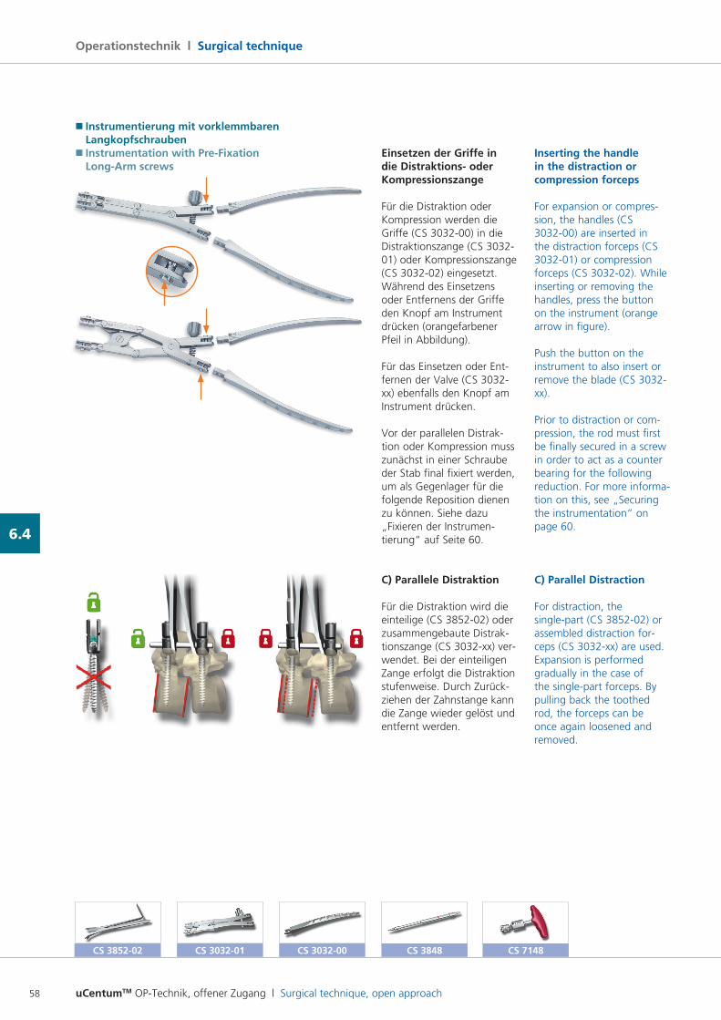
uCentumTM OP-Technik, offener Zugang l Surgical technique, open approach58
Operationstechnik l Surgical technique
6.4
Einsetzen der Griffe in die Distraktions- oder Kompressionszange
Für die Distraktion oder Kompression werden die Griffe (CS 303200) in die Distraktionszange (CS 303201) oder Kompressionszange (CS 303202) eingesetzt. Während des Einsetzens oder Entfernens der Griffe den Knopf am Instrument drücken (orangefarbener Pfeil in Abbildung).
Für das Einsetzen oder Entfernen der Valve (CS 3032xx) ebenfalls den Knopf am Instrument drücken.
Vor der parallelen Distraktion oder Kompression muss zunächst in einer Schraube der Stab final fixiert werden, um als Gegenlager für die folgende Reposition dienen zu können. Siehe dazu „Fixieren der Instrumentierung“ auf Seite 60.
C) Parallele Distraktion
Für die Distraktion wird die einteilige (CS 385202) oder zusammengebaute Distraktionszange (CS 3032xx) verwendet. Bei der einteiligen Zange erfolgt die Distraktion stufenweise. Durch Zurückziehen der Zahnstange kann die Zange wieder gelöst und entfernt werden.
Inserting the handle in the distraction or compression forceps
For expansion or compression, the handles (CS 303200) are inserted in the distraction forceps (CS 303201) or compression forceps (CS 303202). While inserting or removing the handles, press the button on the instrument (orange arrow in figure).
Push the button on the instrument to also insert or remove the blade (CS 3032xx).
Prior to distraction or compression, the rod must first be finally secured in a screw in order to act as a counter bearing for the following reduction. For more information on this, see „Securing the instrumentation“ on page 60.
C) Parallel Distraction
For distraction, the singlepart (CS 385202) or assembled distraction forceps (CS 3032xx) are used. Expansion is performed gradually in the case of the singlepart forceps. By pulling back the toothed rod, the forceps can be once again loosened and removed.
CS 3032-00CS 3032-01CS 3852-02 CS 3848 CS 7148
� Instrumentierung mit vorklemmbaren Langkopfschrauben� Instrumentation with Pre-Fixation Long-Arm screws
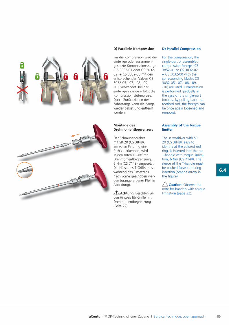
uCentumTM OP-Technik, offener Zugang l Surgical technique, open approach 59
6.4
D) Parallele Kompression
Für die Kompression wird die einteilige oder zusammengesetzte Kompressionszange (CS 385201 oder CS 303202 + CS 303200 mit den entsprechenden Valven CS 303205, 07, 08, 09, 10) verwendet. Bei der einteiligen Zange erfolgt die Kompression stufenweise. Durch Zurückziehen der Zahnstange kann die Zange wieder gelöst und entfernt werden.
Montage des Drehmomentbegrenzers
Der Schraubendreher mit SR 20 (CS 3848), am roten Farbring einfach zu erkennen, wird in den roten TGriff mit Drehmomentbegrenzung, 6 Nm (CS 7148) eingesetzt. Die Hülse des TGriffs muss während des Einsetzens nach vorne geschoben werden (orangefarbener Pfeil in Abbildung).
! Achtung: Beachten Sie den Hinweis für Griffe mit Drehmomentbegrenzung (Seite 22).
D) Parallel Compression
For the compression, the singlepart or assembled compression forceps (CS 385201 or CS 303202 + CS 303200 with the corresponding blades CS 303205, 07, 08, 09, 10) are used. Compression is performed gradually in the case of the singlepart forceps. By pulling back the toothed rod, the forceps can be once again loosened and removed.
Assembly of the torque limiter
The screwdriver with SR 20 (CS 3848), easy to identify at the colored red ring, is inserted into the red Thandle with torque limitation, 6 Nm (CS 7148). The sleeve of the Thandle must be pushed forward during insertion (orange arrow in the figure).
! Caution: Observe the note for handels with torque limitation (page 22).
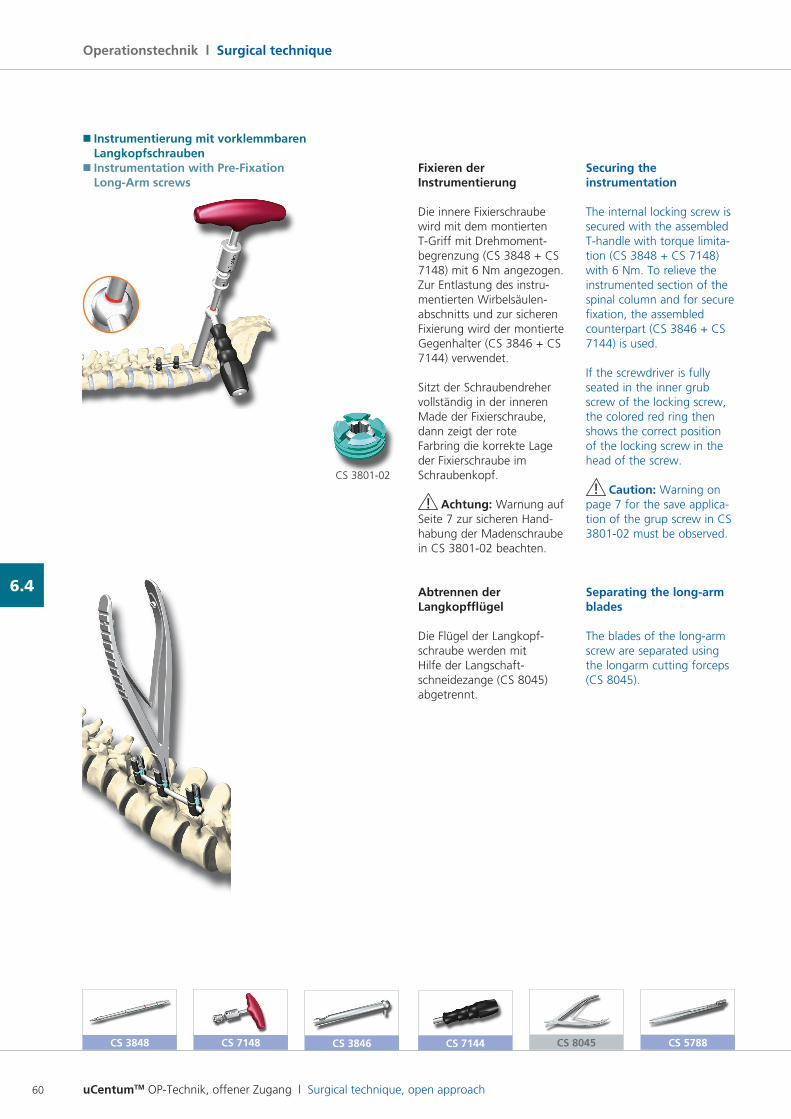
uCentumTM OP-Technik, offener Zugang l Surgical technique, open approach60
Operationstechnik l Surgical technique
6.4
Fixieren der Instrumentierung
Die innere Fixierschraube wird mit dem montierten TGriff mit Drehmomentbegrenzung (CS 3848 + CS 7148) mit 6 Nm angezogen. Zur Entlastung des instru mentierten Wirbelsäulenabschnitts und zur sicheren Fixierung wird der montierte Gegenhalter (CS 3846 + CS 7144) verwendet.
Sitzt der Schraubendreher vollständig in der inneren Made der Fixierschraube, dann zeigt der rote Farbring die korrekte Lage der Fixierschraube im Schraubenkopf.
! Achtung: Warnung auf Seite 7 zur sicheren Hand habung der Madenschraube in CS 380102 beachten.
Abtrennen der Langkopfflügel
Die Flügel der Langkopfschraube werden mit Hilfe der Langschaftschneidezange (CS 8045) abgetrennt.
Securing the instrumentation
The internal locking screw is secured with the assembled Thandle with torque limitation (CS 3848 + CS 7148) with 6 Nm. To relieve the instrumented section of the spinal column and for secure fixation, the assembled counterpart (CS 3846 + CS 7144) is used.
If the screwdriver is fully seated in the inner grub screw of the locking screw, the colored red ring then shows the correct position of the locking screw in the head of the screw.
! Caution: Warning on page 7 for the save application of the grup screw in CS 380102 must be observed.
Separating the long-arm blades
The blades of the longarm screw are separated using the longarm cutting forceps (CS 8045).
CS 3848 CS 7148 CS 3846 CS 7144 CS 8045 CS 5788
� Instrumentierung mit vorklemmbaren Langkopfschrauben� Instrumentation with Pre-Fixation Long-Arm screws
CS 380102
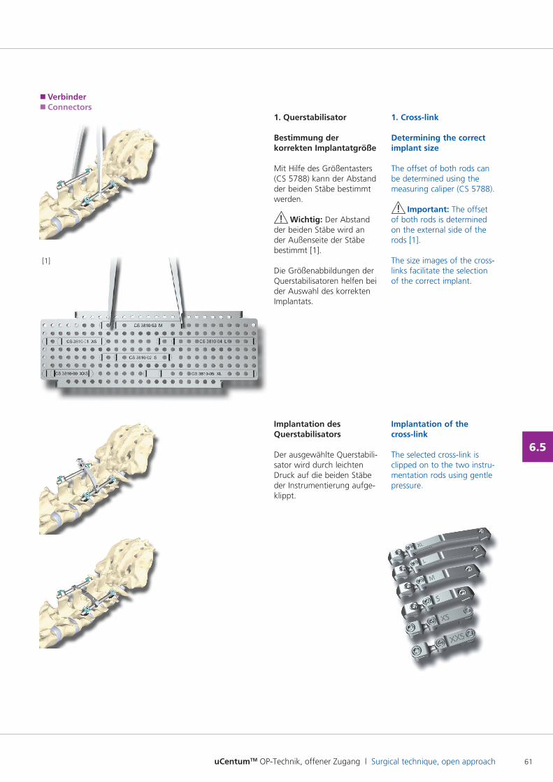
uCentumTM OP-Technik, offener Zugang l Surgical technique, open approach 61
6.5
1. Querstabilisator
Bestimmung der korrekten Implantatgröße
Mit Hilfe des Größentasters (CS 5788) kann der Abstand der beiden Stäbe bestimmt werden.
! Wichtig: Der Abstand der beiden Stäbe wird an der Außenseite der Stäbe bestimmt [1].
Die Größenabbildungen der Querstabilisatoren helfen bei der Auswahl des korrekten Implantats.
Implantation des Querstabilisators
Der ausgewählte Querstabilisator wird durch leichten Druck auf die beiden Stäbe der Instrumentierung aufgeklippt.
1. Cross-link
Determining the correct implant size
The offset of both rods can be determined using the measuring caliper (CS 5788).
! Important: The offset of both rods is determined on the external side of the rods [1].
The size images of the crosslinks facilitate the selection of the correct implant.
Implantation of the cross-link
The selected crosslink is clipped on to the two instrumentation rods using gentle pressure.
[1]
� Verbinder� Connectors
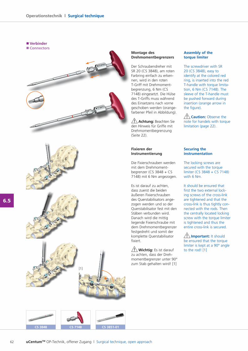
uCentumTM OP-Technik, offener Zugang l Surgical technique, open approach62
Operationstechnik l Surgical technique
6.5
Montage des Drehmomentbegrenzers
Der Schraubendreher mit SR 20 (CS 3848), am roten Farbring einfach zu erken nen, wird in den roten TGriff mit Drehmomentbegrenzung, 6 Nm (CS 7148) eingesetzt. Die Hülse des TGriffs muss während des Einsetzens nach vorne geschoben werden (orangefarbener Pfeil in Abbildung).
! Achtung: Beachten Sie den Hinweis für Griffe mit Drehmomentbegrenzung (Seite 22).
Fixieren der Instrumentierung
Die Fixierschrauben werden mit dem Drehmomentbegrenzer (CS 3848 + CS 7148) mit 6 Nm angezogen.
Es ist darauf zu achten, dass zuerst die beiden äußeren Fixierschrauben des Querstabilisators angezogen werden und so der Querstabilisator fest mit den Stäben verbunden wird. Danach wird die mittig liegende Fixierschraube mit dem Drehmomentbegrenzer festgedreht und somit der komplette Querstabilisator fixiert.
! Wichtig: Es ist darauf zu achten, dass der Drehmomentbegrenzer unter 90° zum Stab gehalten wird! [1]
Assembly of the torque limiter
The screwdriver with SR 20 (CS 3848), easy to identify at the colored red ring, is inserted into the red Thandle with torque limitation, 6 Nm (CS 7148). The sleeve of the Thandle must be pushed forward during insertion (orange arrow in the figure).
! Caution: Observe the note for handels with torque limitation (page 22).
Securing the instrumentation
The locking screws are secured with the torque limiter (CS 3848 + CS 7148) with 6 Nm.
It should be ensured that first the two external locking screws of the crosslink are tightened and that the crosslink is thus tightly connected with the rods. Then the centrally located locking screw with the torque limiter is tightened and thus the entire crosslink is secured.
! Important: It should be ensured that the torque limiter is kept at a 90° angle to the rod! [1]
CS 3848 CS 7148
[1]
� Verbinder� Connectors
CS 3851-01
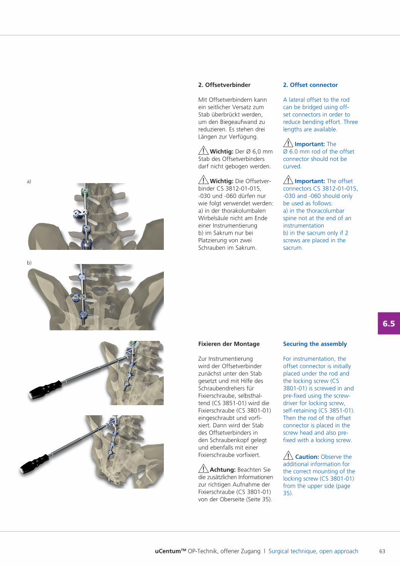
uCentumTM OP-Technik, offener Zugang l Surgical technique, open approach 63
6.5
2. Offsetverbinder
Mit Offsetverbindern kann ein seitlicher Versatz zum Stab überbrückt werden, um den Biegeaufwand zu reduzieren. Es stehen drei Längen zur Verfügung.
! Wichtig: Der Ø 6,0 mm Stab des Offsetverbinders darf nicht gebogen werden.
! Wichtig: Die Offsetverbinder CS 381201015, 030 und 060 dürfen nur wie folgt verwendet werden:a) in der thorakolumbalen Wirbelsäule nicht am Ende einer Instrumentierungb) im Sakrum nur bei Platzierung von zwei Schrauben im Sakrum.
Fixieren der Montage
Zur Instrumentierung wird der Offsetverbinder zunächst unter den Stab gesetzt und mit Hilfe des Schraubendrehers für Fixierschraube, selbsthaltend (CS 385101) wird die Fixierschraube (CS 380101)eingeschraubt und vorfixiert. Dann wird der Stab des Offsetverbinders in den Schraubenkopf gelegt und ebenfalls mit einer Fixierschraube vorfixiert.
! Achtung: Beachten Sie die zusätzlichen Informationen zur richtigen Aufnahme der Fixierschraube (CS 380101) von der Oberseite (Seite 35).
2. Offset connector
A lateral offset to the rod can be bridged using offset connectors in order to reduce bending effort. Three lengths are available.
! Important: The Ø 6.0 mm rod of the offset connector should not be curved.
! Important: The offset connectors CS 381201015, 030 and 060 should only be used as follows:a) in the thoracolumbar spine not at the end of an instrumentationb) in the sacrum only if 2 screws are placed in the sacrum.
Securing the assembly
For instrumentation, the offset connector is initially placed under the rod and the locking screw (CS 380101) is screwed in and prefixed using the screwdriver for locking screw, selfretaining (CS 385101). Then the rod of the offset connector is placed in the screw head and also prefixed with a locking screw.
! Caution: Observe the additional information for the correct mounting of the locking screw (CS 380101) from the upper side (page 35).
a)
b)
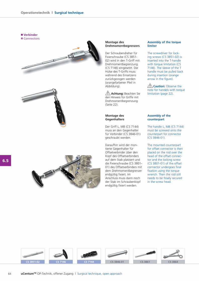
uCentumTM OP-Technik, offener Zugang l Surgical technique, open approach64
Operationstechnik l Surgical technique
6.5
Assembly of the torque limiter
The screwdriver for locking screws (CS 385102) is inserted into the Thandle with torque limitation (CS 7146). The sleeve of the T handle must be pulled back during insertion (orange arrow in the figure).
! Caution: Observe the note for handels with torque limitation (page 22).
Assembly of the counterpart
The handle L, M8 (CS 7144) must be screwed onto the counterpart for connector (CS 384601).
The mounted counterpart for offset connector is then placed on the rod over the head of the offset connector and the locking screw (CS 380101) of the offset connector undergoes final fixation using the torque wrench. Then the rod still needs to be finally secured in the screw head.
Montage des Drehmomentbegrenzers
Der Schraubendreher für Fixierschraube (CS 385102) wird in den TGriff mit Drehmomentbegrenzung (CS 7146) eingesetzt. Die Hülse des TGriffs muss während des Einsetzens zurückgezogen werden (orangefarbener Pfeil in Abbildung).
! Achtung: Beachten Sie den Hinweis für Griffe mit Drehmomentbegrenzung (Seite 22).
Montage des Gegenhalters
Der Griff L, M8 (CS 7144) muss an den Gegenhalter für Verbinder (CS 384601) geschraubt werden.
Daraufhin wird der montierte Gegenhalter für Offsetverbinder über den Kopf des Offsetverbinders auf dem Stab platziert und die Fixierschraube (CS 380101) des Offsetverbinders mit dem Drehmomentbegrenzer endgültig fixiert. Im Anschluss muss dann noch der Stab im Schraubenkopf endgültig fixiert werden.
� Verbinder� Connectors
CS 3851-02 CS 3846-01 CS 3861 CS 3864CS 7146 CS 7144
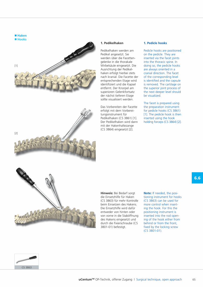
uCentumTM OP-Technik, offener Zugang l Surgical technique, open approach 65
6.6
[1]
1. Pedikelhaken
Pedikelhaken werden am Pedikel angesetzt. Sie werden über die Facetten gelenke in die thorakale Wirbelsäule eingesetzt. Die Ausrichtung der Pedikelhaken erfolgt hierbei stets nach kranial. Die Facette der entsprechenden Etage wird identifiziert und die Kapsel entfernt. Der Knorpel am superioren Gelenkfortsatz der nächst tieferen Etage sollte visualisiert werden.
Das Vorbereiten der Facette erfolgt mit dem Vorbereitungsinstrument für Pedikelhaken (CS 3861) [1].Der Pedikelhaken wird dann mit der Hakenhaltezange (CS 3864) eingesetzt [2].
Hinweis: Bei Bedarf sorgt die Einsetzhilfe für Haken (CS 3863) für mehr Kontrolle beim Einsetzen des Hakens. Die Einsetzhilfe wird dafür entweder von hinten oder von vorne in die Staböffnung des Hakens eingesetzt und durch die Fixierschraube (CS 380101) befestigt.
1. Pedicle hooks
Pedicle hooks are positioned on the pedicle. They are inserted via the facet joints into the thoracic spine. In doing so, the pedicle hooks are always oriented in a cranial direction. The facet of the corresponding level is identified and the capsule is removed. The cartilage on the superior joint process of the next deeper level should be visualized.
The facet is prepared using the preparation instrument for pedicle hooks (CS 3861) [1]. The pedicle hook is then inserted using the hook holding forceps (CS 3864) [2].
Note: If needed, the positioning instrument for hooks (CS 3863) can be used for more control when inserting the hook. For this the positioning instrument is inserted into the rod opening of the hook either from behind or from the front, fixed by the locking screw (CS 380101).
� Haken� Hooks
CS 3863
[2]
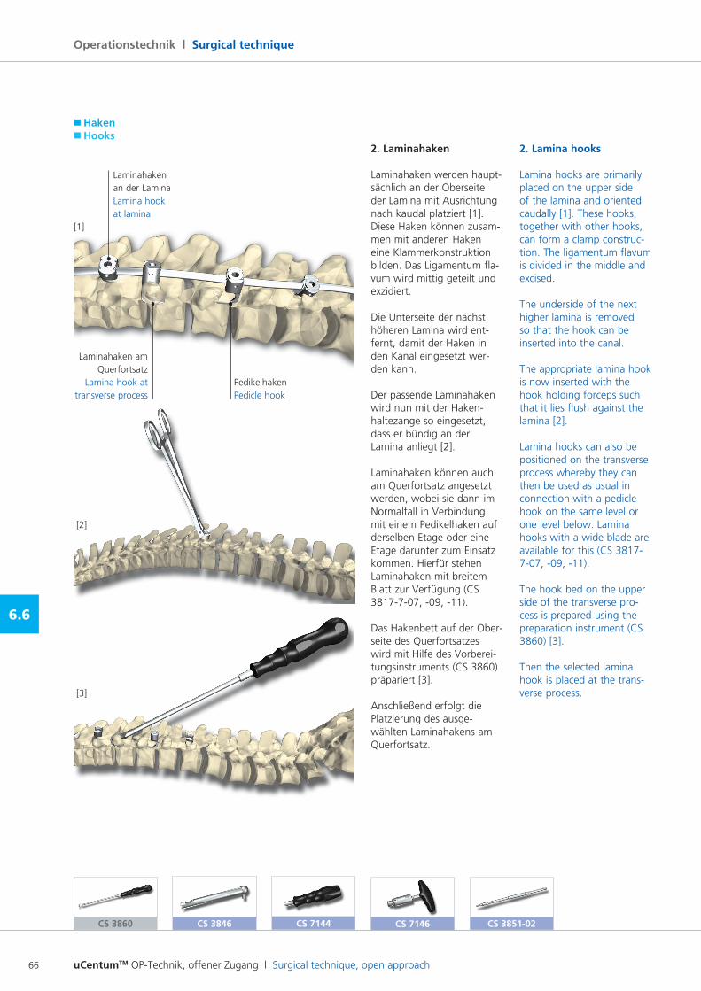
uCentumTM OP-Technik, offener Zugang l Surgical technique, open approach66
Operationstechnik l Surgical technique
6.6
� Haken� Hooks
CS 3860 CS 7144CS 3846 CS 3851-02CS 7146
2. Laminahaken
Laminahaken werden hauptsächlich an der Oberseite der Lamina mit Ausrichtung nach kaudal platziert [1]. Diese Haken können zusammen mit anderen Haken eine Klammerkonstruktion bilden. Das Ligamentum flavum wird mittig geteilt und exzidiert.
Die Unterseite der nächst höheren Lamina wird entfernt, damit der Haken in den Kanal eingesetzt werden kann.
Der passende Laminahaken wird nun mit der Hakenhaltezange so eingesetzt, dass er bündig an der Lamina anliegt [2].
Laminahaken können auch am Querfortsatz angesetzt werden, wobei sie dann im Normalfall in Verbindung mit einem Pedikelhaken auf derselben Etage oder eine Etage darunter zum Einsatz kommen. Hierfür stehen Laminahaken mit breitem Blatt zur Verfügung (CS 3817707, 09, 11).
Das Hakenbett auf der Oberseite des Querfortsatzes wird mit Hilfe des Vorbereitungsinstruments (CS 3860) präpariert [3].
Anschließend erfolgt die Platzierung des ausgewählten Laminahakens am Querfortsatz.
[1]
Laminahaken am Querfortsatz
Lamina hook at transverse process
Laminahaken an der LaminaLamina hook at lamina
Pedikelhaken Pedicle hook
[2]
[3]
2. Lamina hooks
Lamina hooks are primarily placed on the upper side of the lamina and oriented caudally [1]. These hooks, together with other hooks, can form a clamp construction. The ligamentum flavum is divided in the middle and excised.
The underside of the next higher lamina is removed so that the hook can be inserted into the canal.
The appropriate lamina hook is now inserted with the hook holding forceps such that it lies flush against the lamina [2].
Lamina hooks can also be positioned on the transverse process whereby they can then be used as usual in connection with a pedicle hook on the same level or one level below. Lamina hooks with a wide blade are available for this (CS 3817707, 09, 11).
The hook bed on the upper side of the transverse process is prepared using the preparation instrument (CS 3860) [3].
Then the selected lamina hook is placed at the transverse process.
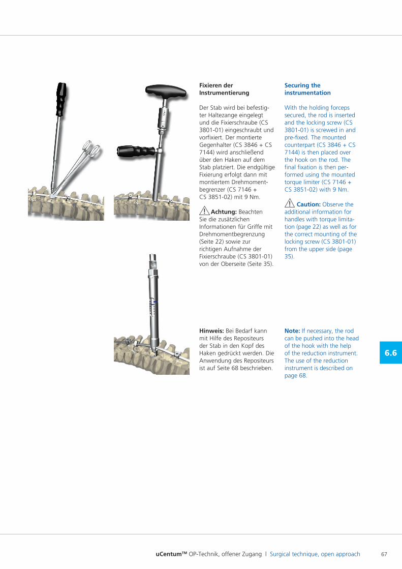
uCentumTM OP-Technik, offener Zugang l Surgical technique, open approach 67
6.6
Fixieren der Instrumentierung
Der Stab wird bei befestigter Haltezange eingelegt und die Fixierschraube (CS 380101) eingeschraubt und vorfixiert. Der montierte Gegenhalter (CS 3846 + CS 7144) wird anschließend über den Haken auf dem Stab platziert. Die endgültige Fixierung erfolgt dann mit montiertem Drehmoment begrenzer (CS 7146 + CS 385102) mit 9 Nm.
! Achtung: Beachten Sie die zusätzlichen Informationen für Griffe mit Drehmomentbegrenzung (Seite 22) sowie zur richtigen Aufnahme der Fixierschraube (CS 380101) von der Oberseite (Seite 35).
Hinweis: Bei Bedarf kann mit Hilfe des Repositeurs der Stab in den Kopf des Haken gedrückt werden. Die Anwendung des Repositeurs ist auf Seite 68 beschrieben.
Securing the instrumentation
With the holding forceps secured, the rod is inserted and the locking screw (CS 380101) is screwed in and prefixed. The mounted counterpart (CS 3846 + CS 7144) is then placed over the hook on the rod. The final fixation is then performed using the mounted torque limiter (CS 7146 + CS 385102) with 9 Nm.
! Caution: Observe the additional information for handles with torque limitation (page 22) as well as for the correct mounting of the locking screw (CS 380101) from the upper side (page 35).
Note: If necessary, the rod can be pushed into the head of the hook with the help of the reduction instrument. The use of the reduction instrument is described on page 68.
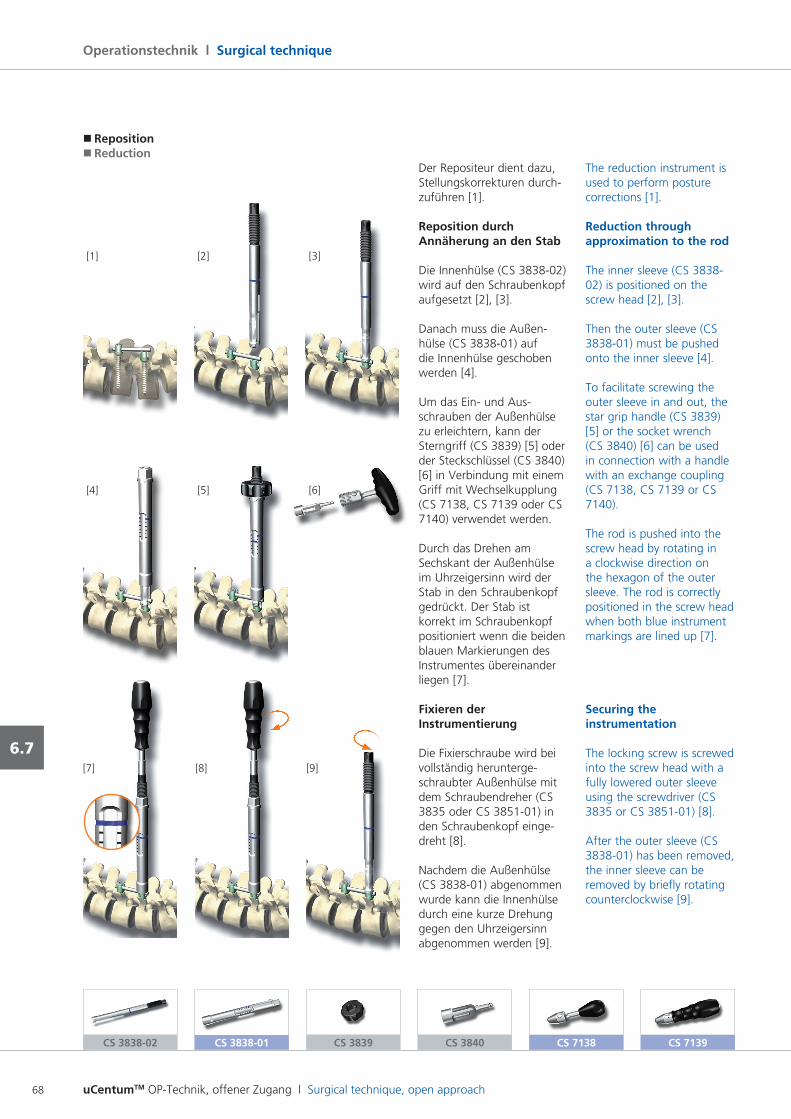
uCentumTM OP-Technik, offener Zugang l Surgical technique, open approach68
Operationstechnik l Surgical technique
6.7
Der Repositeur dient dazu, Stellungskorrekturen durchzuführen [1].
Reposition durch Annäherung an den Stab
Die Innenhülse (CS 383802) wird auf den Schraubenkopf aufgesetzt [2], [3].
Danach muss die Außenhülse (CS 383801) auf die Innenhülse geschoben werden [4].
Um das Ein und Ausschrauben der Außenhülse zu erleichtern, kann der Sterngriff (CS 3839) [5] oder der Steckschlüssel (CS 3840) [6] in Verbindung mit einem Griff mit Wechselkupplung (CS 7138, CS 7139 oder CS 7140) verwendet werden.
Durch das Drehen am Sechskant der Außenhülse im Uhrzeigersinn wird der Stab in den Schraubenkopf gedrückt. Der Stab ist korrekt im Schraubenkopf positioniert wenn die beiden blauen Markierungen des Instrumentes übereinander liegen [7].
Fixieren der Instrumentierung
Die Fixierschraube wird bei vollständig heruntergeschraubter Außenhülse mit dem Schraubendreher (CS 3835 oder CS 385101) in den Schraubenkopf eingedreht [8].
Nachdem die Außenhülse (CS 383801) abgenommen wurde kann die Innenhülse durch eine kurze Drehung gegen den Uhrzeigersinn abgenommen werden [9].
The reduction instrument is used to perform posture corrections [1].
Reduction through approximation to the rod
The inner sleeve (CS 383802) is positioned on the screw head [2], [3].
Then the outer sleeve (CS 383801) must be pushed onto the inner sleeve [4].
To facilitate screwing the outer sleeve in and out, the star grip handle (CS 3839) [5] or the socket wrench (CS 3840) [6] can be used in connection with a handle with an exchange coupling (CS 7138, CS 7139 or CS 7140).
The rod is pushed into the screw head by rotating in a clockwise direction on the hexagon of the outer sleeve. The rod is correctly positioned in the screw head when both blue instrument markings are lined up [7].
Securing the instrumentation
The locking screw is screwed into the screw head with a fully lowered outer sleeve using the screwdriver (CS 3835 or CS 385101) [8].
After the outer sleeve (CS 383801) has been removed, the inner sleeve can be removed by briefly rotating counterclockwise [9].
[2] [1]
[5]
[3]
[4]
[8][7] [9]
[6]
� Reposition� Reduction
CS 3838-01CS 3838-02 CS 3839 CS 3840 CS 7138 CS 7139
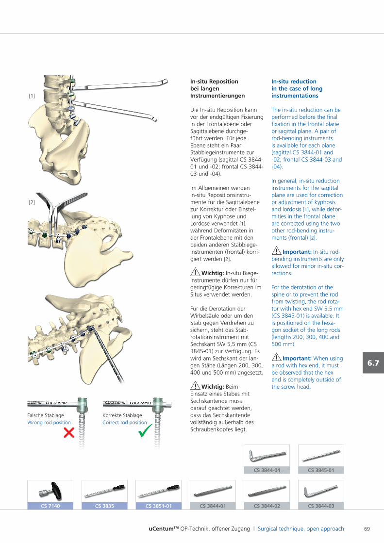
uCentumTM OP-Technik, offener Zugang l Surgical technique, open approach 69
6.7
In-situ Reposition bei langen Instrumentierungen
Die Insitu Reposition kann vor der endgültigen Fixierung in der Frontalebene oder Sagittalebene durchgeführt werden. Für jede Ebene steht ein Paar Stabbiegeinstrumente zur Verfügung (sagittal CS 384401 und 02; frontal CS 384403 und 04).
Im Allgemeinen werden Insitu Repositionsinstrumente für die Sagittalebene zur Korrektur oder Einstellung von Kyphose und Lordose verwendet [1], während Deformitäten in der Frontalebene mit den beiden anderen Stabbiegeinstrumenten (frontal) korrigiert werden [2].
! Wichtig: Insitu Biegeinstrumente dürfen nur für geringfügige Korrekturen im Situs verwendet werden.
Für die Derotation der Wirbelsäule oder um den Stab gegen Verdrehen zu sichern, steht das Stabrotationsinstrument mit Sechskant SW 5,5 mm (CS 384501) zur Verfügung. Es wird am Sechskant der langen Stäbe (Längen 200, 300, 400 und 500 mm) angesetzt.
! Wichtig: Beim Einsatz eines Stabes mit Sechskantende muss darauf geachtet werden, dass das Sechskantende vollständig außerhalb des Schraubenkopfes liegt.
In-situ reduction in the case of long instrumentations
The insitu reduction can be performed before the final fixation in the frontal plane or sagittal plane. A pair of rodbending instruments is available for each plane (sagittal CS 384401 and 02; frontal CS 384403 and 04).
In general, insitu reduction instruments for the sagittal plane are used for correction or adjustment of kyphosis and lordosis [1], while deformities in the frontal plane are corrected using the two other rodbending instruments (frontal) [2].
! Important: Insitu rodbending instruments are only allowed for minor insitu corrections.
For the derotation of the spine or to prevent the rod from twisting, the rod rotator with hex end SW 5.5 mm (CS 384501) is available. It is positioned on the hexagon socket of the long rods (lengths 200, 300, 400 and 500 mm).
! Important: When using a rod with hex end, it must be observed that the hex end is completely outside of the screw head.
CS 3844-01 CS 3844-03CS 3844-02
CS 3844-04 CS 3845-01
[1]
[2]
CS 7140 CS 3835 CS 3851-01
Falsche StablageWrong rod position
Korrekte StablageCorrect rod position
ür
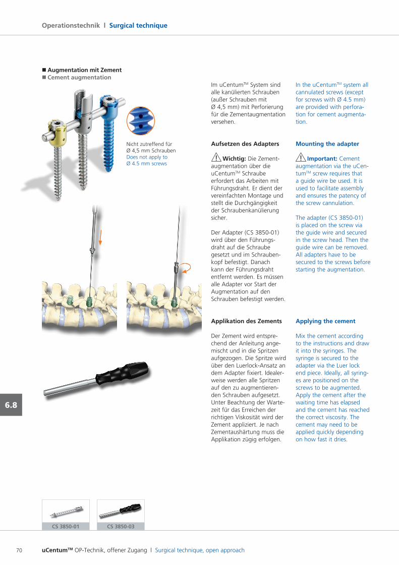
uCentumTM OP-Technik, offener Zugang l Surgical technique, open approach70
Operationstechnik l Surgical technique
6.8
Im uCentumTM System sind alle kanülierten Schrauben (außer Schrauben mit Ø 4,5 mm) mit Perforierung für die Zementaugmentation versehen.
Aufsetzen des Adapters
! Wichtig: Die Zementaugmentation über die uCentumTM Schraube erfordert das Arbeiten mit Führungsdraht. Er dient der vereinfachten Montage und stellt die Durchgängigkeit der Schraubenkanülierung sicher.
Der Adapter (CS 385001) wird über den Führungsdraht auf die Schraube gesetzt und im Schraubenkopf befestigt. Danach kann der Führungsdraht entfernt werden. Es müssen alle Adapter vor Start der Augmentation auf den Schrauben befestigt werden.
Applikation des Zements
Der Zement wird entsprechend der Anleitung angemischt und in die Spritzen aufgezogen. Die Spritze wird über den LuerlockAnsatz an dem Adapter fixiert. Idealer weise werden alle Spritzen auf den zu augmentierenden Schrauben aufgesetzt. Unter Beachtung der Wartezeit für das Erreichen der richtigen Viskosität wird der Zement appliziert. Je nach Zementaushärtung muss die Applikation zügig erfolgen.
In the uCentumTM system all cannulated screws (except for screws with Ø 4.5 mm) are provided with perforation for cement augmentation.
Mounting the adapter
! Important: Cement augmentation via the uCentumTM screw requires that a guide wire be used. It is used to facilitate assembly and ensures the patency of the screw cannulation.
The adapter (CS 385001) is placed on the screw via the guide wire and secured in the screw head. Then the guide wire can be removed. All adapters have to be secured to the screws before starting the augmentation.
Applying the cement
Mix the cement according to the instructions and draw it into the syringes. The syringe is secured to the adapter via the Luer lock end piece. Ideally, all syringes are positioned on the screws to be augmented.Apply the cement after the waiting time has elapsed and the cement has reached the correct viscosity. The cement may need to be applied quickly depending on how fast it dries.
� Augmentation mit Zement� Cement augmentation
Nicht zutreffend für Ø 4,5 mm SchraubenDoes not apply to Ø 4.5 mm screws
CS 3850-01 CS 3850-03
uCentumTM OP-Technik, offener Zugang l Surgical technique, open approach 71
6.8
! Wichtig: Laterale Bildwandlerkontrolle wird empfohlen.
Der Adapter ist nur für den einmaligen Gebrauch vorgesehen.
Die Adapter werden auf den Schrauben belassen, bis der Zement ausgehärtet ist, um einen Rückfluss zu vermeiden. Dann wird der Adapter mit dem Griff für Injektionsadapter (CS 385003) gelöst und entfernt.
! Important: Lateral Carm control is recommended.
The adapter is intended only for single use.
To prevent cement back flow, leave the adapters on the screws until the cement has dried. Then the adapter is released using the handle for injection adapter (CS 385003) and removed.
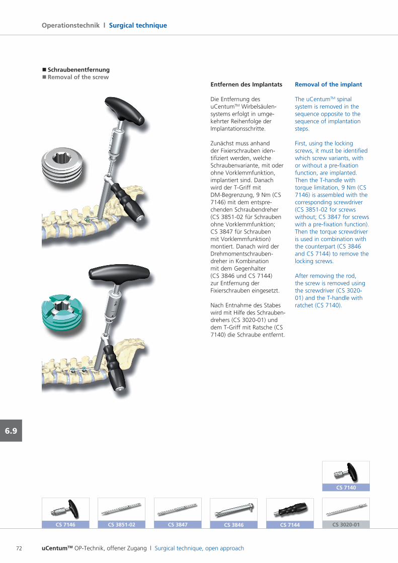
uCentumTM OP-Technik, offener Zugang l Surgical technique, open approach72
Operationstechnik l Surgical technique
6.9
CS 7140
Removal of the implant
The uCentumTM spinal system is removed in the sequence opposite to the sequence of implantation steps.
First, using the locking screws, it must be identified which screw variants, with or without a prefixation function, are implanted. Then the Thandle with torque limitation, 9 Nm (CS 7146) is assembled with the corresponding screwdriver (CS 385102 for screws without; CS 3847 for screws with a prefixation function). Then the torque screwdriver is used in combination with the counterpart (CS 3846 and CS 7144) to remove the locking screws.
After removing the rod, the screw is removed using the screwdriver (CS 302001) and the Thandle with ratchet (CS 7140).
CS 3020-01
Entfernen des Implantats
Die Entfernung des uCentumTM Wirbelsäulensystems erfolgt in umgekehrter Reihenfolge der Implantationsschritte.
Zunächst muss anhand der Fixierschrauben identifiziert werden, welche Schraubenvariante, mit oder ohne Vorklemmfunktion, implantiert sind. Danach wird der TGriff mit DMBegrenzung, 9 Nm (CS 7146) mit dem entsprechenden Schraubendreher (CS 385102 für Schrauben ohne Vorklemmfunktion; CS 3847 für Schrauben mit Vorklemmfunktion) montiert. Danach wird der Drehmomentschraubendreher in Kombination mit dem Gegenhalter (CS 3846 und CS 7144) zur Entfernung der Fixierschrauben eingesetzt.
Nach Entnahme des Stabes wird mit Hilfe des Schraubendrehers (CS 302001) und dem TGriff mit Ratsche (CS 7140) die Schraube entfernt.
CS 7144
� Schraubenentfernung� Removal of the screw
CS 7146 CS 3851-02 CS 3847 CS 3846
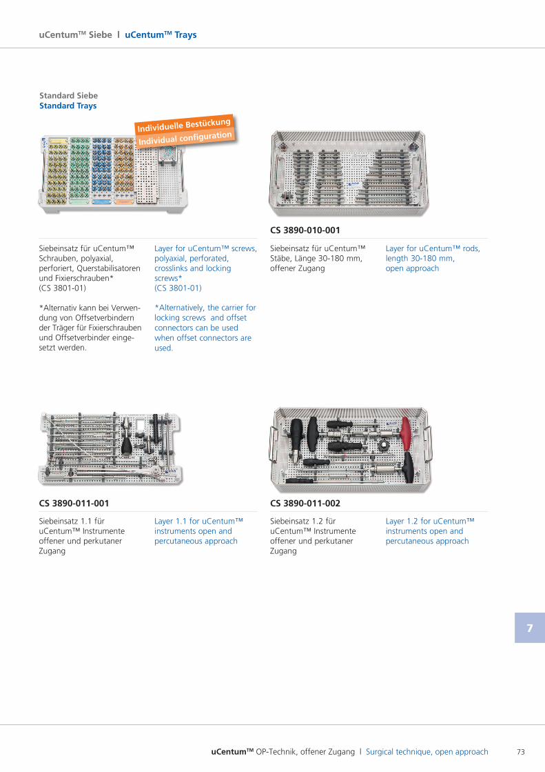
uCentumTM OP-Technik, offener Zugang l Surgical technique, open approach 73
7
uCentumTM Siebe l uCentumTM Trays
CS 3890-010-001
CS 3890-011-001 CS 3890-011-002
Standard SiebeStandard Trays
Siebeinsatz für uCentum™ Schrauben, polyaxial, perforiert, Querstabilisatoren und Fixierschrauben*(CS 380101)
*Alternativ kann bei Verwen dung von Offsetverbindern der Träger für Fixierschrauben und Offsetverbinder eingesetzt werden.
Layer for uCentum™ screws, polyaxial, perforated, crosslinks and locking screws*(CS 380101)
*Alternatively, the carrier for locking screws and offset connectors can be used when offset connectors are used.
Siebeinsatz 1.1 für uCentum™ Instrumente offener und perkutaner Zugang
Layer 1.1 for uCentum™ instruments open and percutaneous approach
Siebeinsatz für uCentum™ Stäbe, Länge 30180 mm, offener Zugang
Layer for uCentum™ rods, length 30180 mm, open approach
Siebeinsatz 1.2 für uCentum™ Instrumente offener und perkutaner Zugang
Layer 1.2 for uCentum™ instruments open and percutaneous approach
Individuelle Bestückung
Individual configuration
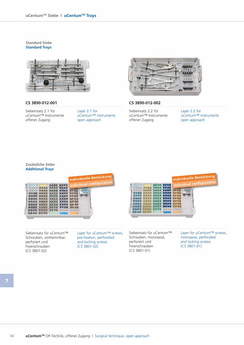
uCentumTM OP-Technik, offener Zugang l Surgical technique, open approach74
7
uCentumTM Siebe l uCentumTM Trays
Siebeinsatz für uCentum™ Schrauben, monoaxial, perforiert und Fixierschrauben(CS 380101)
Layer for uCentum™ screws, monoaxial, perforated and locking screws(CS 380101)
Individuelle Bestückung
Individual configuration
CS 3890-012-001 CS 3890-012-002
Standard SiebeStandard Trays
Siebeinsatz 2.1 für uCentum™ Instrumente offener Zugang
Layer 2.1 for uCentum™ instruments open approach
Siebeinsatz 2.2 für uCentum™ Instrumente offener Zugang
Layer 2.2 for uCentum™ instruments open approach
Zusätzliche SiebeAdditional Trays
Siebeinsatz für uCentum™ Schrauben, vorklemmbar, perforiert und Fixierschrauben(CS 380102)
Layer for uCentum™ screws, prefixation, perforated and locking screws(CS 380102)
Individuelle Bestückung
Individual configuration
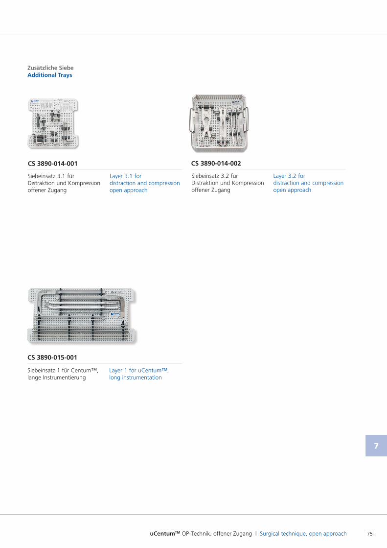
uCentumTM OP-Technik, offener Zugang l Surgical technique, open approach 75
7
Zusätzliche SiebeAdditional Trays
CS 3890-014-001
Siebeinsatz 3.1 für Distraktion und Kompression offener Zugang
Layer 3.1 for distraction and compression open approach
CS 3890-014-002
Siebeinsatz 3.2 für Distraktion und Kompression offener Zugang
Layer 3.2 for distraction and compression open approach
Siebeinsatz 1 für Centum™, lange Instrumentierung
Layer 1 for uCentum™, long instrumentation
CS 3890-015-001
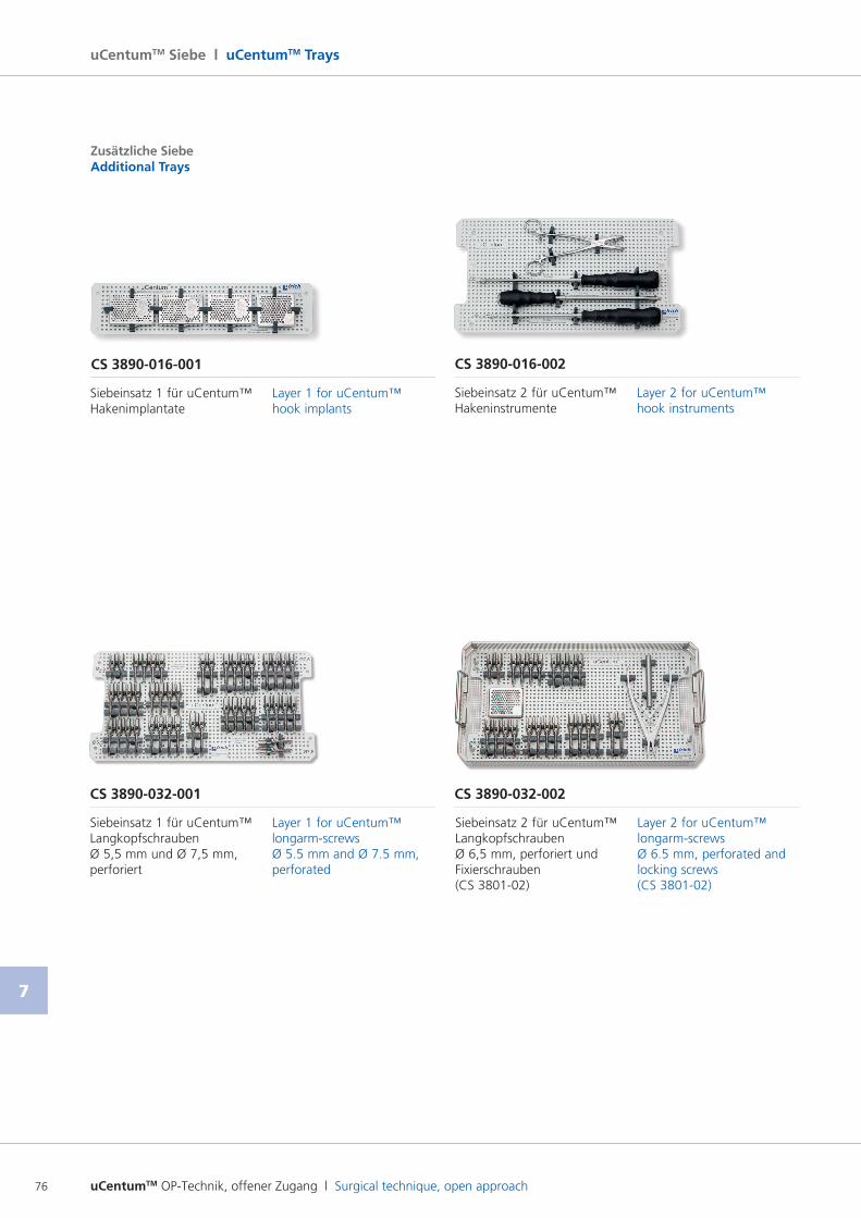
uCentumTM OP-Technik, offener Zugang l Surgical technique, open approach76
7
uCentumTM Siebe l uCentumTM Trays
Zusätzliche SiebeAdditional Trays
CS 3890-032-001 CS 3890-032-002
Siebeinsatz 1 für uCentum™ Langkopfschrauben Ø 5,5 mm und Ø 7,5 mm, perforiert
Layer 1 for uCentum™ longarmscrews Ø 5.5 mm and Ø 7.5 mm, perforated
Siebeinsatz 2 für uCentum™ Langkopfschrauben Ø 6,5 mm, perforiert und Fixierschrauben (CS 380102)
Layer 2 for uCentum™ longarmscrews Ø 6.5 mm, perforated and locking screws(CS 380102)
Siebeinsatz 1 für uCentum™ Hakenimplantate
Layer 1 for uCentum™ hook implants
CS 3890-016-001
Siebeinsatz 2 für uCentum™ Hakeninstrumente
Layer 2 for uCentum™ hook instruments
CS 3890-016-002
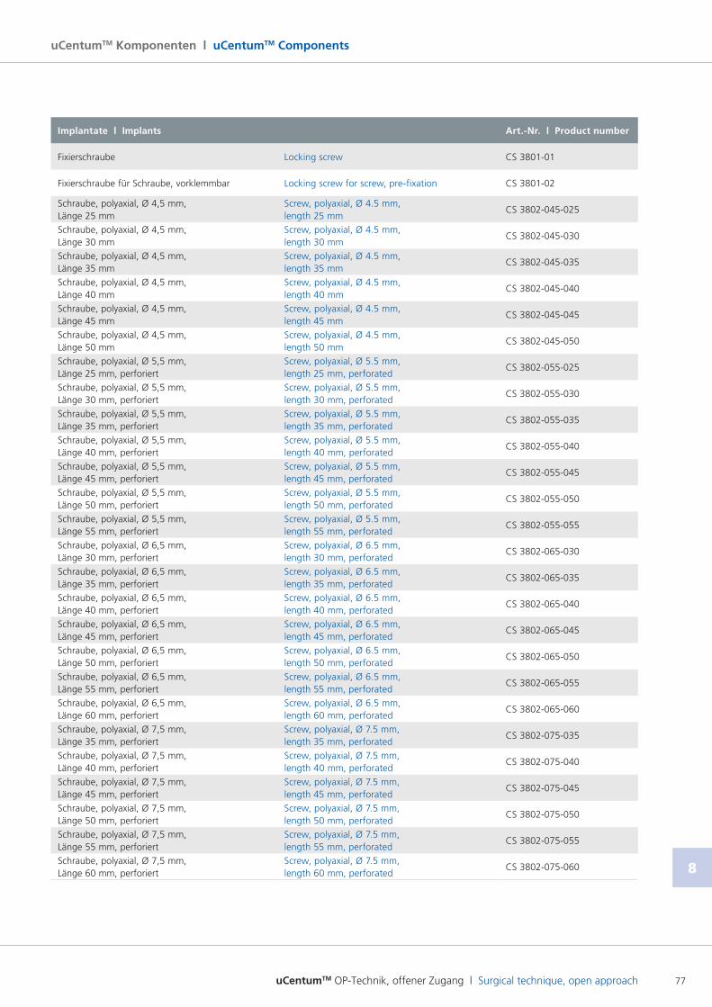
uCentumTM OP-Technik, offener Zugang l Surgical technique, open approach 77
8
uCentumTM Komponenten l uCentumTM Components
Implantate l Implants Art.-Nr. l Product number
Fixierschraube Locking screw CS 380101
Fixierschraube für Schraube, vorklemmbar Locking screw for screw, prefixation CS 380102
Schraube, polyaxial, Ø 4,5 mm, Länge 25 mm
Screw, polyaxial, Ø 4.5 mm, length 25 mm
CS 3802045025
Schraube, polyaxial, Ø 4,5 mm, Länge 30 mm
Screw, polyaxial, Ø 4.5 mm, length 30 mm
CS 3802045030
Schraube, polyaxial, Ø 4,5 mm, Länge 35 mm
Screw, polyaxial, Ø 4.5 mm, length 35 mm
CS 3802045035
Schraube, polyaxial, Ø 4,5 mm, Länge 40 mm
Screw, polyaxial, Ø 4.5 mm, length 40 mm
CS 3802045040
Schraube, polyaxial, Ø 4,5 mm, Länge 45 mm
Screw, polyaxial, Ø 4.5 mm, length 45 mm
CS 3802045045
Schraube, polyaxial, Ø 4,5 mm, Länge 50 mm
Screw, polyaxial, Ø 4.5 mm, length 50 mm
CS 3802045050
Schraube, polyaxial, Ø 5,5 mm, Länge 25 mm, perforiert
Screw, polyaxial, Ø 5.5 mm, length 25 mm, perforated
CS 3802055025
Schraube, polyaxial, Ø 5,5 mm, Länge 30 mm, perforiert
Screw, polyaxial, Ø 5.5 mm, length 30 mm, perforated
CS 3802055030
Schraube, polyaxial, Ø 5,5 mm, Länge 35 mm, perforiert
Screw, polyaxial, Ø 5.5 mm, length 35 mm, perforated
CS 3802055035
Schraube, polyaxial, Ø 5,5 mm, Länge 40 mm, perforiert
Screw, polyaxial, Ø 5.5 mm, length 40 mm, perforated
CS 3802055040
Schraube, polyaxial, Ø 5,5 mm, Länge 45 mm, perforiert
Screw, polyaxial, Ø 5.5 mm, length 45 mm, perforated
CS 3802055045
Schraube, polyaxial, Ø 5,5 mm, Länge 50 mm, perforiert
Screw, polyaxial, Ø 5.5 mm, length 50 mm, perforated
CS 3802055050
Schraube, polyaxial, Ø 5,5 mm, Länge 55 mm, perforiert
Screw, polyaxial, Ø 5.5 mm, length 55 mm, perforated
CS 3802055055
Schraube, polyaxial, Ø 6,5 mm, Länge 30 mm, perforiert
Screw, polyaxial, Ø 6.5 mm, length 30 mm, perforated
CS 3802065030
Schraube, polyaxial, Ø 6,5 mm, Länge 35 mm, perforiert
Screw, polyaxial, Ø 6.5 mm, length 35 mm, perforated
CS 3802065035
Schraube, polyaxial, Ø 6,5 mm, Länge 40 mm, perforiert
Screw, polyaxial, Ø 6.5 mm, length 40 mm, perforated
CS 3802065040
Schraube, polyaxial, Ø 6,5 mm, Länge 45 mm, perforiert
Screw, polyaxial, Ø 6.5 mm, length 45 mm, perforated
CS 3802065045
Schraube, polyaxial, Ø 6,5 mm, Länge 50 mm, perforiert
Screw, polyaxial, Ø 6.5 mm, length 50 mm, perforated
CS 3802065050
Schraube, polyaxial, Ø 6,5 mm, Länge 55 mm, perforiert
Screw, polyaxial, Ø 6.5 mm, length 55 mm, perforated
CS 3802065055
Schraube, polyaxial, Ø 6,5 mm, Länge 60 mm, perforiert
Screw, polyaxial, Ø 6.5 mm, length 60 mm, perforated
CS 3802065060
Schraube, polyaxial, Ø 7,5 mm, Länge 35 mm, perforiert
Screw, polyaxial, Ø 7.5 mm, length 35 mm, perforated
CS 3802075035
Schraube, polyaxial, Ø 7,5 mm, Länge 40 mm, perforiert
Screw, polyaxial, Ø 7.5 mm, length 40 mm, perforated
CS 3802075040
Schraube, polyaxial, Ø 7,5 mm, Länge 45 mm, perforiert
Screw, polyaxial, Ø 7.5 mm, length 45 mm, perforated
CS 3802075045
Schraube, polyaxial, Ø 7,5 mm, Länge 50 mm, perforiert
Screw, polyaxial, Ø 7.5 mm, length 50 mm, perforated
CS 3802075050
Schraube, polyaxial, Ø 7,5 mm, Länge 55 mm, perforiert
Screw, polyaxial, Ø 7.5 mm, length 55 mm, perforated
CS 3802075055
Schraube, polyaxial, Ø 7,5 mm, Länge 60 mm, perforiert
Screw, polyaxial, Ø 7.5 mm, length 60 mm, perforated
CS 3802075060
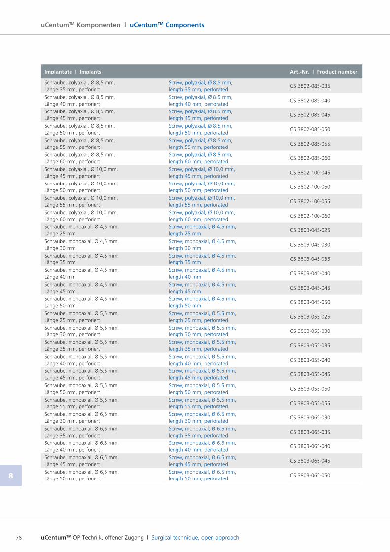
uCentumTM OP-Technik, offener Zugang l Surgical technique, open approach78
8
uCentumTM Komponenten l uCentumTM Components
Implantate l Implants Art.-Nr. l Product number
Schraube, polyaxial, Ø 8,5 mm, Länge 35 mm, perforiert
Screw, polyaxial, Ø 8.5 mm, length 35 mm, perforated
CS 3802085035
Schraube, polyaxial, Ø 8,5 mm, Länge 40 mm, perforiert
Screw, polyaxial, Ø 8.5 mm, length 40 mm, perforated
CS 3802085040
Schraube, polyaxial, Ø 8,5 mm, Länge 45 mm, perforiert
Screw, polyaxial, Ø 8.5 mm, length 45 mm, perforated
CS 3802085045
Schraube, polyaxial, Ø 8,5 mm, Länge 50 mm, perforiert
Screw, polyaxial, Ø 8.5 mm, length 50 mm, perforated
CS 3802085050
Schraube, polyaxial, Ø 8,5 mm, Länge 55 mm, perforiert
Screw, polyaxial, Ø 8.5 mm, length 55 mm, perforated
CS 3802085055
Schraube, polyaxial, Ø 8,5 mm, Länge 60 mm, perforiert
Screw, polyaxial, Ø 8.5 mm, length 60 mm, perforated
CS 3802085060
Schraube, polyaxial, Ø 10,0 mm, Länge 45 mm, perforiert
Screw, polyaxial, Ø 10,0 mm, length 45 mm, perforated
CS 3802100045
Schraube, polyaxial, Ø 10,0 mm, Länge 50 mm, perforiert
Screw, polyaxial, Ø 10,0 mm, length 50 mm, perforated
CS 3802100050
Schraube, polyaxial, Ø 10,0 mm, Länge 55 mm, perforiert
Screw, polyaxial, Ø 10,0 mm, length 55 mm, perforated
CS 3802100055
Schraube, polyaxial, Ø 10,0 mm, Länge 60 mm, perforiert
Screw, polyaxial, Ø 10,0 mm, length 60 mm, perforated
CS 3802100060
Schraube, monoaxial, Ø 4,5 mm, Länge 25 mm
Screw, monoaxial, Ø 4.5 mm, length 25 mm
CS 3803045025
Schraube, monoaxial, Ø 4,5 mm, Länge 30 mm
Screw, monoaxial, Ø 4.5 mm, length 30 mm
CS 3803045030
Schraube, monoaxial, Ø 4,5 mm, Länge 35 mm
Screw, monoaxial, Ø 4.5 mm, length 35 mm
CS 3803045035
Schraube, monoaxial, Ø 4,5 mm, Länge 40 mm
Screw, monoaxial, Ø 4.5 mm, length 40 mm
CS 3803045040
Schraube, monoaxial, Ø 4,5 mm, Länge 45 mm
Screw, monoaxial, Ø 4.5 mm, length 45 mm
CS 3803045045
Schraube, monoaxial, Ø 4,5 mm, Länge 50 mm
Screw, monoaxial, Ø 4.5 mm, length 50 mm
CS 3803045050
Schraube, monoaxial, Ø 5,5 mm, Länge 25 mm, perforiert
Screw, monoaxial, Ø 5.5 mm, length 25 mm, perforated
CS 3803055025
Schraube, monoaxial, Ø 5,5 mm, Länge 30 mm, perforiert
Screw, monoaxial, Ø 5.5 mm, length 30 mm, perforated
CS 3803055030
Schraube, monoaxial, Ø 5,5 mm, Länge 35 mm, perforiert
Screw, monoaxial, Ø 5.5 mm, length 35 mm, perforated
CS 3803055035
Schraube, monoaxial, Ø 5,5 mm, Länge 40 mm, perforiert
Screw, monoaxial, Ø 5.5 mm, length 40 mm, perforated
CS 3803055040
Schraube, monoaxial, Ø 5,5 mm, Länge 45 mm, perforiert
Screw, monoaxial, Ø 5.5 mm, length 45 mm, perforated
CS 3803055045
Schraube, monoaxial, Ø 5,5 mm, Länge 50 mm, perforiert
Screw, monoaxial, Ø 5.5 mm, length 50 mm, perforated
CS 3803055050
Schraube, monoaxial, Ø 5,5 mm, Länge 55 mm, perforiert
Screw, monoaxial, Ø 5.5 mm, length 55 mm, perforated
CS 3803055055
Schraube, monoaxial, Ø 6,5 mm, Länge 30 mm, perforiert
Screw, monoaxial, Ø 6.5 mm, length 30 mm, perforated
CS 3803065030
Schraube, monoaxial, Ø 6,5 mm, Länge 35 mm, perforiert
Screw, monoaxial, Ø 6.5 mm, length 35 mm, perforated
CS 3803065035
Schraube, monoaxial, Ø 6,5 mm, Länge 40 mm, perforiert
Screw, monoaxial, Ø 6.5 mm, length 40 mm, perforated
CS 3803065040
Schraube, monoaxial, Ø 6,5 mm, Länge 45 mm, perforiert
Screw, monoaxial, Ø 6.5 mm, length 45 mm, perforated
CS 3803065045
Schraube, monoaxial, Ø 6,5 mm, Länge 50 mm, perforiert
Screw, monoaxial, Ø 6.5 mm, length 50 mm, perforated
CS 3803065050
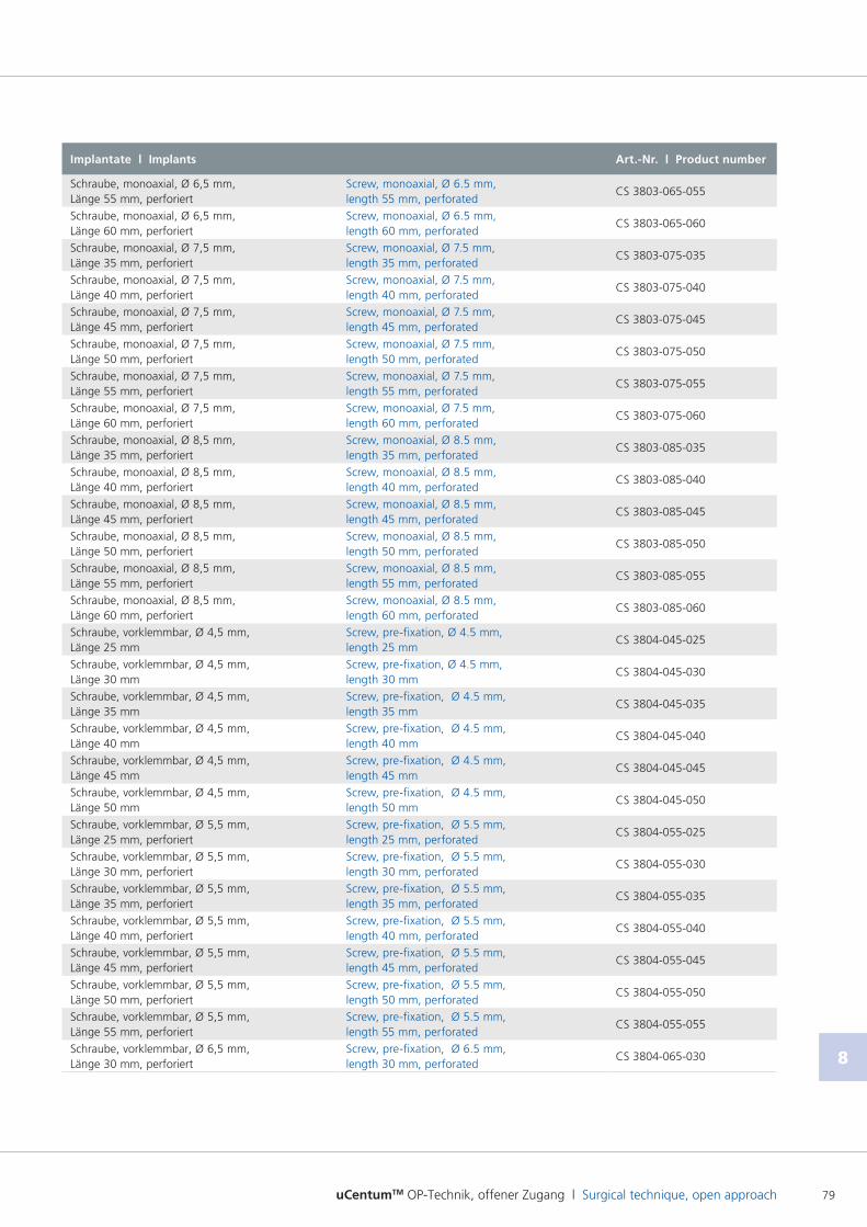
uCentumTM OP-Technik, offener Zugang l Surgical technique, open approach 79
8
Implantate l Implants Art.-Nr. l Product number
Schraube, monoaxial, Ø 6,5 mm, Länge 55 mm, perforiert
Screw, monoaxial, Ø 6.5 mm, length 55 mm, perforated
CS 3803065055
Schraube, monoaxial, Ø 6,5 mm, Länge 60 mm, perforiert
Screw, monoaxial, Ø 6.5 mm, length 60 mm, perforated
CS 3803065060
Schraube, monoaxial, Ø 7,5 mm, Länge 35 mm, perforiert
Screw, monoaxial, Ø 7.5 mm, length 35 mm, perforated
CS 3803075035
Schraube, monoaxial, Ø 7,5 mm, Länge 40 mm, perforiert
Screw, monoaxial, Ø 7.5 mm, length 40 mm, perforated
CS 3803075040
Schraube, monoaxial, Ø 7,5 mm, Länge 45 mm, perforiert
Screw, monoaxial, Ø 7.5 mm, length 45 mm, perforated
CS 3803075045
Schraube, monoaxial, Ø 7,5 mm, Länge 50 mm, perforiert
Screw, monoaxial, Ø 7.5 mm, length 50 mm, perforated
CS 3803075050
Schraube, monoaxial, Ø 7,5 mm, Länge 55 mm, perforiert
Screw, monoaxial, Ø 7.5 mm, length 55 mm, perforated
CS 3803075055
Schraube, monoaxial, Ø 7,5 mm, Länge 60 mm, perforiert
Screw, monoaxial, Ø 7.5 mm, length 60 mm, perforated
CS 3803075060
Schraube, monoaxial, Ø 8,5 mm, Länge 35 mm, perforiert
Screw, monoaxial, Ø 8.5 mm, length 35 mm, perforated
CS 3803085035
Schraube, monoaxial, Ø 8,5 mm, Länge 40 mm, perforiert
Screw, monoaxial, Ø 8.5 mm, length 40 mm, perforated
CS 3803085040
Schraube, monoaxial, Ø 8,5 mm, Länge 45 mm, perforiert
Screw, monoaxial, Ø 8.5 mm, length 45 mm, perforated
CS 3803085045
Schraube, monoaxial, Ø 8,5 mm, Länge 50 mm, perforiert
Screw, monoaxial, Ø 8.5 mm, length 50 mm, perforated
CS 3803085050
Schraube, monoaxial, Ø 8,5 mm, Länge 55 mm, perforiert
Screw, monoaxial, Ø 8.5 mm, length 55 mm, perforated
CS 3803085055
Schraube, monoaxial, Ø 8,5 mm, Länge 60 mm, perforiert
Screw, monoaxial, Ø 8.5 mm, length 60 mm, perforated
CS 3803085060
Schraube, vorklemmbar, Ø 4,5 mm, Länge 25 mm
Screw, prefixation, Ø 4.5 mm, length 25 mm
CS 3804045025
Schraube, vorklemmbar, Ø 4,5 mm, Länge 30 mm
Screw, prefixation, Ø 4.5 mm, length 30 mm
CS 3804045030
Schraube, vorklemmbar, Ø 4,5 mm, Länge 35 mm
Screw, prefixation, Ø 4.5 mm, length 35 mm
CS 3804045035
Schraube, vorklemmbar, Ø 4,5 mm, Länge 40 mm
Screw, prefixation, Ø 4.5 mm, length 40 mm
CS 3804045040
Schraube, vorklemmbar, Ø 4,5 mm, Länge 45 mm
Screw, prefixation, Ø 4.5 mm, length 45 mm
CS 3804045045
Schraube, vorklemmbar, Ø 4,5 mm, Länge 50 mm
Screw, prefixation, Ø 4.5 mm, length 50 mm
CS 3804045050
Schraube, vorklemmbar, Ø 5,5 mm, Länge 25 mm, perforiert
Screw, prefixation, Ø 5.5 mm, length 25 mm, perforated
CS 3804055025
Schraube, vorklemmbar, Ø 5,5 mm, Länge 30 mm, perforiert
Screw, prefixation, Ø 5.5 mm, length 30 mm, perforated
CS 3804055030
Schraube, vorklemmbar, Ø 5,5 mm, Länge 35 mm, perforiert
Screw, prefixation, Ø 5.5 mm, length 35 mm, perforated
CS 3804055035
Schraube, vorklemmbar, Ø 5,5 mm, Länge 40 mm, perforiert
Screw, prefixation, Ø 5.5 mm, length 40 mm, perforated
CS 3804055040
Schraube, vorklemmbar, Ø 5,5 mm, Länge 45 mm, perforiert
Screw, prefixation, Ø 5.5 mm, length 45 mm, perforated
CS 3804055045
Schraube, vorklemmbar, Ø 5,5 mm, Länge 50 mm, perforiert
Screw, prefixation, Ø 5.5 mm, length 50 mm, perforated
CS 3804055050
Schraube, vorklemmbar, Ø 5,5 mm, Länge 55 mm, perforiert
Screw, prefixation, Ø 5.5 mm, length 55 mm, perforated
CS 3804055055
Schraube, vorklemmbar, Ø 6,5 mm, Länge 30 mm, perforiert
Screw, prefixation, Ø 6.5 mm, length 30 mm, perforated
CS 3804065030
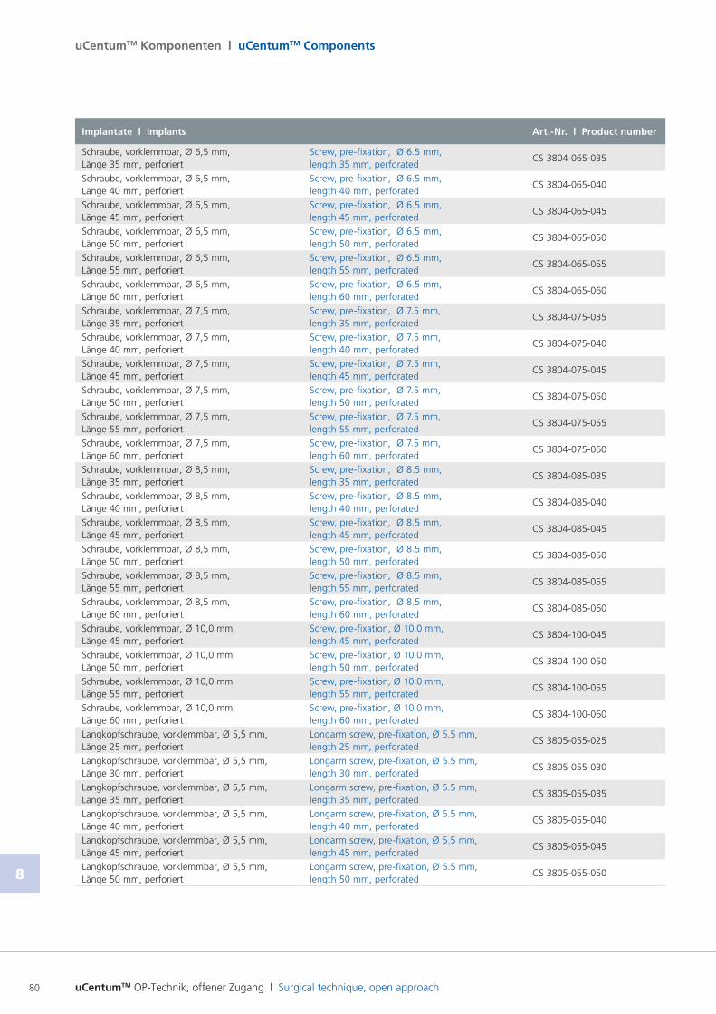
uCentumTM OP-Technik, offener Zugang l Surgical technique, open approach80
8
uCentumTM Komponenten l uCentumTM Components
Implantate l Implants Art.-Nr. l Product number
Schraube, vorklemmbar, Ø 6,5 mm, Länge 35 mm, perforiert
Screw, prefixation, Ø 6.5 mm, length 35 mm, perforated
CS 3804065035
Schraube, vorklemmbar, Ø 6,5 mm, Länge 40 mm, perforiert
Screw, prefixation, Ø 6.5 mm, length 40 mm, perforated
CS 3804065040
Schraube, vorklemmbar, Ø 6,5 mm, Länge 45 mm, perforiert
Screw, prefixation, Ø 6.5 mm, length 45 mm, perforated
CS 3804065045
Schraube, vorklemmbar, Ø 6,5 mm, Länge 50 mm, perforiert
Screw, prefixation, Ø 6.5 mm, length 50 mm, perforated
CS 3804065050
Schraube, vorklemmbar, Ø 6,5 mm, Länge 55 mm, perforiert
Screw, prefixation, Ø 6.5 mm, length 55 mm, perforated
CS 3804065055
Schraube, vorklemmbar, Ø 6,5 mm, Länge 60 mm, perforiert
Screw, prefixation, Ø 6.5 mm, length 60 mm, perforated
CS 3804065060
Schraube, vorklemmbar, Ø 7,5 mm, Länge 35 mm, perforiert
Screw, prefixation, Ø 7.5 mm, length 35 mm, perforated
CS 3804075035
Schraube, vorklemmbar, Ø 7,5 mm, Länge 40 mm, perforiert
Screw, prefixation, Ø 7.5 mm, length 40 mm, perforated
CS 3804075040
Schraube, vorklemmbar, Ø 7,5 mm, Länge 45 mm, perforiert
Screw, prefixation, Ø 7.5 mm, length 45 mm, perforated
CS 3804075045
Schraube, vorklemmbar, Ø 7,5 mm, Länge 50 mm, perforiert
Screw, prefixation, Ø 7.5 mm, length 50 mm, perforated
CS 3804075050
Schraube, vorklemmbar, Ø 7,5 mm, Länge 55 mm, perforiert
Screw, prefixation, Ø 7.5 mm, length 55 mm, perforated
CS 3804075055
Schraube, vorklemmbar, Ø 7,5 mm, Länge 60 mm, perforiert
Screw, prefixation, Ø 7.5 mm, length 60 mm, perforated
CS 3804075060
Schraube, vorklemmbar, Ø 8,5 mm, Länge 35 mm, perforiert
Screw, prefixation, Ø 8.5 mm, length 35 mm, perforated
CS 3804085035
Schraube, vorklemmbar, Ø 8,5 mm, Länge 40 mm, perforiert
Screw, prefixation, Ø 8.5 mm, length 40 mm, perforated
CS 3804085040
Schraube, vorklemmbar, Ø 8,5 mm, Länge 45 mm, perforiert
Screw, prefixation, Ø 8.5 mm, length 45 mm, perforated
CS 3804085045
Schraube, vorklemmbar, Ø 8,5 mm, Länge 50 mm, perforiert
Screw, prefixation, Ø 8.5 mm, length 50 mm, perforated
CS 3804085050
Schraube, vorklemmbar, Ø 8,5 mm, Länge 55 mm, perforiert
Screw, prefixation, Ø 8.5 mm, length 55 mm, perforated
CS 3804085055
Schraube, vorklemmbar, Ø 8,5 mm, Länge 60 mm, perforiert
Screw, prefixation, Ø 8.5 mm, length 60 mm, perforated
CS 3804085060
Schraube, vorklemmbar, Ø 10,0 mm, Länge 45 mm, perforiert
Screw, prefixation, Ø 10.0 mm, length 45 mm, perforated
CS 3804100045
Schraube, vorklemmbar, Ø 10,0 mm, Länge 50 mm, perforiert
Screw, prefixation, Ø 10.0 mm, length 50 mm, perforated
CS 3804100050
Schraube, vorklemmbar, Ø 10,0 mm, Länge 55 mm, perforiert
Screw, prefixation, Ø 10.0 mm, length 55 mm, perforated
CS 3804100055
Schraube, vorklemmbar, Ø 10,0 mm, Länge 60 mm, perforiert
Screw, prefixation, Ø 10.0 mm, length 60 mm, perforated
CS 3804100060
Langkopfschraube, vorklemmbar, Ø 5,5 mm, Länge 25 mm, perforiert
Longarm screw, prefixation, Ø 5.5 mm, length 25 mm, perforated
CS 3805055025
Langkopfschraube, vorklemmbar, Ø 5,5 mm, Länge 30 mm, perforiert
Longarm screw, prefixation, Ø 5.5 mm, length 30 mm, perforated
CS 3805055030
Langkopfschraube, vorklemmbar, Ø 5,5 mm, Länge 35 mm, perforiert
Longarm screw, prefixation, Ø 5.5 mm, length 35 mm, perforated
CS 3805055035
Langkopfschraube, vorklemmbar, Ø 5,5 mm, Länge 40 mm, perforiert
Longarm screw, prefixation, Ø 5.5 mm, length 40 mm, perforated
CS 3805055040
Langkopfschraube, vorklemmbar, Ø 5,5 mm, Länge 45 mm, perforiert
Longarm screw, prefixation, Ø 5.5 mm, length 45 mm, perforated
CS 3805055045
Langkopfschraube, vorklemmbar, Ø 5,5 mm, Länge 50 mm, perforiert
Longarm screw, prefixation, Ø 5.5 mm, length 50 mm, perforated
CS 3805055050
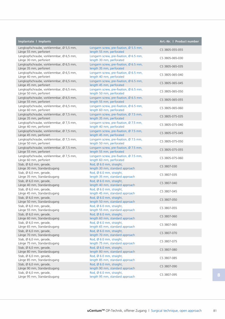
uCentumTM OP-Technik, offener Zugang l Surgical technique, open approach 81
8
Implantate l Implants Art.-Nr. l Product number
Langkopfschraube, vorklemmbar, Ø 5,5 mm, Länge 55 mm, perforiert
Longarm screw, prefixation, Ø 5.5 mm, length 55 mm, perforated
CS 3805055055
Langkopfschraube, vorklemmbar, Ø 6,5 mm, Länge 30 mm, perforiert
Longarm screw, prefixation, Ø 6.5 mm, length 30 mm, perforated
CS 3805065030
Langkopfschraube, vorklemmbar, Ø 6,5 mm, Länge 35 mm, perforiert
Longarm screw, prefixation, Ø 6.5 mm, length 35 mm, perforated
CS 3805065035
Langkopfschraube, vorklemmbar, Ø 6,5 mm, Länge 40 mm, perforiert
Longarm screw, prefixation, Ø 6.5 mm, length 40 mm, perforated
CS 3805065040
Langkopfschraube, vorklemmbar, Ø 6,5 mm, Länge 45 mm, perforiert
Longarm screw, prefixation, Ø 6.5 mm, length 45 mm, perforated
CS 3805065045
Langkopfschraube, vorklemmbar, Ø 6,5 mm, Länge 50 mm, perforiert
Longarm screw, prefixation, Ø 6.5 mm, length 50 mm, perforated
CS 3805065050
Langkopfschraube, vorklemmbar, Ø 6,5 mm, Länge 55 mm, perforiert
Longarm screw, prefixation, Ø 6.5 mm, length 55 mm, perforated
CS 3805065055
Langkopfschraube, vorklemmbar, Ø 6,5 mm, Länge 60 mm, perforiert
Longarm screw, prefixation, Ø 6.5 mm, length 60 mm, perforated
CS 3805065060
Langkopfschraube, vorklemmbar, Ø 7,5 mm, Länge 35 mm, perforiert
Longarm screw, prefixation, Ø 7.5 mm, length 35 mm, perforated
CS 3805075035
Langkopfschraube, vorklemmbar, Ø 7,5 mm, Länge 40 mm, perforiert
Longarm screw, prefixation, Ø 7.5 mm, length 40 mm, perforated
CS 3805075040
Langkopfschraube, vorklemmbar, Ø 7,5 mm, Länge 45 mm, perforiert
Longarm screw, prefixation, Ø 7.5 mm, length 45 mm, perforated
CS 3805075045
Langkopfschraube, vorklemmbar, Ø 7,5 mm, Länge 50 mm, perforiert
Longarm screw, prefixation, Ø 7.5 mm, length 50 mm, perforated
CS 3805075050
Langkopfschraube, vorklemmbar, Ø 7,5 mm, Länge 55 mm, perforiert
Longarm screw, prefixation, Ø 7.5 mm, length 55 mm, perforated
CS 3805075055
Langkopfschraube, vorklemmbar, Ø 7,5 mm, Länge 60 mm, perforiert
Longarm screw, prefixation, Ø 7.5 mm, length 60 mm, perforated
CS 3805075060
Stab, Ø 6,0 mm, gerade, Länge 30 mm, Standardzugang
Rod, Ø 6.0 mm, straight, length 30 mm, standard approach
CS 3807030
Stab, Ø 6,0 mm, gerade, Länge 35 mm, Standardzugang
Rod, Ø 6.0 mm, straight, length 35 mm, standard approach
CS 3807035
Stab, Ø 6,0 mm, gerade, Länge 40 mm, Standardzugang
Rod, Ø 6.0 mm, straight, length 40 mm, standard approach
CS 3807040
Stab, Ø 6,0 mm, gerade, Länge 45 mm, Standardzugang
Rod, Ø 6.0 mm, straight, length 45 mm, standard approach
CS 3807045
Stab, Ø 6,0 mm, gerade, Länge 50 mm, Standardzugang
Rod, Ø 6.0 mm, straight, length 50 mm, standard approach
CS 3807050
Stab, Ø 6,0 mm, gerade, Länge 55 mm, Standardzugang
Rod, Ø 6.0 mm, straight, length 55 mm, standard approach
CS 3807055
Stab, Ø 6,0 mm, gerade, Länge 60 mm, Standardzugang
Rod, Ø 6.0 mm, straight, length 60 mm, standard approach
CS 3807060
Stab, Ø 6,0 mm, gerade, Länge 65 mm, Standardzugang
Rod, Ø 6.0 mm, straight, length 65 mm, standard approach
CS 3807065
Stab, Ø 6,0 mm, gerade, Länge 70 mm, Standardzugang
Rod, Ø 6.0 mm, straight, length 70 mm, standard approach
CS 3807070
Stab, Ø 6,0 mm, gerade, Länge 75 mm, Standardzugang
Rod, Ø 6.0 mm, straight, length 75 mm, standard approach
CS 3807075
Stab, Ø 6,0 mm, gerade, Länge 80 mm, Standardzugang
Rod, Ø 6.0 mm, straight, length 80 mm, standard approach
CS 3807080
Stab, Ø 6,0 mm, gerade, Länge 85 mm, Standardzugang
Rod, Ø 6.0 mm, straight, length 85 mm, standard approach
CS 3807085
Stab, Ø 6,0 mm, gerade, Länge 90 mm, Standardzugang
Rod, Ø 6.0 mm, straight, length 90 mm, standard approach
CS 3807090
Stab, Ø 6,0 mm, gerade, Länge 95 mm, Standardzugang
Rod, Ø 6.0 mm, straight, length 95 mm, standard approach
CS 3807095
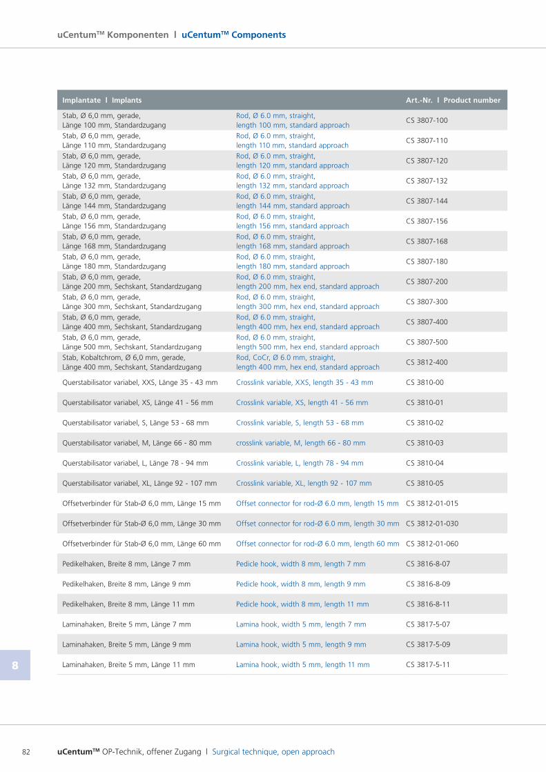
uCentumTM OP-Technik, offener Zugang l Surgical technique, open approach82
8
uCentumTM Komponenten l uCentumTM Components
Implantate l Implants Art.-Nr. l Product number
Stab, Ø 6,0 mm, gerade, Länge 100 mm, Standardzugang
Rod, Ø 6.0 mm, straight, length 100 mm, standard approach
CS 3807100
Stab, Ø 6,0 mm, gerade, Länge 110 mm, Standardzugang
Rod, Ø 6.0 mm, straight, length 110 mm, standard approach
CS 3807110
Stab, Ø 6,0 mm, gerade, Länge 120 mm, Standardzugang
Rod, Ø 6.0 mm, straight, length 120 mm, standard approach
CS 3807120
Stab, Ø 6,0 mm, gerade, Länge 132 mm, Standardzugang
Rod, Ø 6.0 mm, straight, length 132 mm, standard approach
CS 3807132
Stab, Ø 6,0 mm, gerade, Länge 144 mm, Standardzugang
Rod, Ø 6.0 mm, straight, length 144 mm, standard approach
CS 3807144
Stab, Ø 6,0 mm, gerade, Länge 156 mm, Standardzugang
Rod, Ø 6.0 mm, straight, length 156 mm, standard approach
CS 3807156
Stab, Ø 6,0 mm, gerade, Länge 168 mm, Standardzugang
Rod, Ø 6.0 mm, straight, length 168 mm, standard approach
CS 3807168
Stab, Ø 6,0 mm, gerade, Länge 180 mm, Standardzugang
Rod, Ø 6.0 mm, straight, length 180 mm, standard approach
CS 3807180
Stab, Ø 6,0 mm, gerade, Länge 200 mm, Sechskant, Standardzugang
Rod, Ø 6.0 mm, straight, length 200 mm, hex end, standard approach
CS 3807200
Stab, Ø 6,0 mm, gerade, Länge 300 mm, Sechskant, Standardzugang
Rod, Ø 6.0 mm, straight, length 300 mm, hex end, standard approach
CS 3807300
Stab, Ø 6,0 mm, gerade, Länge 400 mm, Sechskant, Standardzugang
Rod, Ø 6.0 mm, straight, length 400 mm, hex end, standard approach
CS 3807400
Stab, Ø 6,0 mm, gerade, Länge 500 mm, Sechskant, Standardzugang
Rod, Ø 6.0 mm, straight, length 500 mm, hex end, standard approach
CS 3807500
Stab, Kobaltchrom, Ø 6,0 mm, gerade, Länge 400 mm, Sechskant, Standardzugang
Rod, CoCr, Ø 6.0 mm, straight, length 400 mm, hex end, standard approach
CS 3812400
Querstabilisator variabel, XXS, Länge 35 43 mm Crosslink variable, XXS, length 35 43 mm CS 381000
Querstabilisator variabel, XS, Länge 41 56 mm Crosslink variable, XS, length 41 56 mm CS 381001
Querstabilisator variabel, S, Länge 53 68 mm Crosslink variable, S, length 53 68 mm CS 381002
Querstabilisator variabel, M, Länge 66 80 mm crosslink variable, M, length 66 80 mm CS 381003
Querstabilisator variabel, L, Länge 78 94 mm Crosslink variable, L, length 78 94 mm CS 381004
Querstabilisator variabel, XL, Länge 92 107 mm Crosslink variable, XL, length 92 107 mm CS 381005
Offsetverbinder für StabØ 6,0 mm, Länge 15 mm Offset connector for rodØ 6.0 mm, length 15 mm CS 381201015
Offsetverbinder für StabØ 6,0 mm, Länge 30 mm Offset connector for rodØ 6.0 mm, length 30 mm CS 381201030
Offsetverbinder für StabØ 6,0 mm, Länge 60 mm Offset connector for rodØ 6.0 mm, length 60 mm CS 381201060
Pedikelhaken, Breite 8 mm, Länge 7 mm Pedicle hook, width 8 mm, length 7 mm CS 3816807
Pedikelhaken, Breite 8 mm, Länge 9 mm Pedicle hook, width 8 mm, length 9 mm CS 3816809
Pedikelhaken, Breite 8 mm, Länge 11 mm Pedicle hook, width 8 mm, length 11 mm CS 3816811
Laminahaken, Breite 5 mm, Länge 7 mm Lamina hook, width 5 mm, length 7 mm CS 3817507
Laminahaken, Breite 5 mm, Länge 9 mm Lamina hook, width 5 mm, length 9 mm CS 3817509
Laminahaken, Breite 5 mm, Länge 11 mm Lamina hook, width 5 mm, length 11 mm CS 3817511
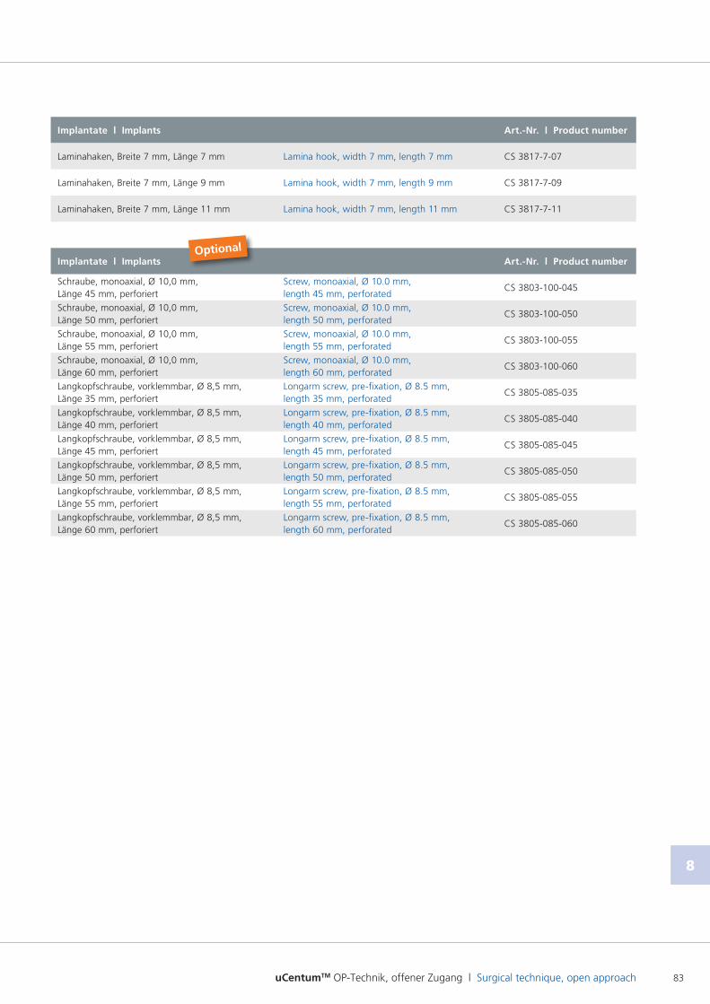
uCentumTM OP-Technik, offener Zugang l Surgical technique, open approach 83
8
Implantate l Implants Art.-Nr. l Product number
Laminahaken, Breite 7 mm, Länge 7 mm Lamina hook, width 7 mm, length 7 mm CS 3817707
Laminahaken, Breite 7 mm, Länge 9 mm Lamina hook, width 7 mm, length 9 mm CS 3817709
Laminahaken, Breite 7 mm, Länge 11 mm Lamina hook, width 7 mm, length 11 mm CS 3817711
Implantate l Implants Art.-Nr. l Product number
Schraube, monoaxial, Ø 10,0 mm, Länge 45 mm, perforiert
Screw, monoaxial, Ø 10.0 mm, length 45 mm, perforated
CS 3803100045
Schraube, monoaxial, Ø 10,0 mm, Länge 50 mm, perforiert
Screw, monoaxial, Ø 10.0 mm, length 50 mm, perforated
CS 3803100050
Schraube, monoaxial, Ø 10,0 mm, Länge 55 mm, perforiert
Screw, monoaxial, Ø 10.0 mm, length 55 mm, perforated
CS 3803100055
Schraube, monoaxial, Ø 10,0 mm, Länge 60 mm, perforiert
Screw, monoaxial, Ø 10.0 mm, length 60 mm, perforated
CS 3803100060
Langkopfschraube, vorklemmbar, Ø 8,5 mm, Länge 35 mm, perforiert
Longarm screw, prefixation, Ø 8.5 mm, length 35 mm, perforated
CS 3805085035
Langkopfschraube, vorklemmbar, Ø 8,5 mm, Länge 40 mm, perforiert
Longarm screw, prefixation, Ø 8.5 mm, length 40 mm, perforated
CS 3805085040
Langkopfschraube, vorklemmbar, Ø 8,5 mm, Länge 45 mm, perforiert
Longarm screw, prefixation, Ø 8.5 mm, length 45 mm, perforated
CS 3805085045
Langkopfschraube, vorklemmbar, Ø 8,5 mm, Länge 50 mm, perforiert
Longarm screw, prefixation, Ø 8.5 mm, length 50 mm, perforated
CS 3805085050
Langkopfschraube, vorklemmbar, Ø 8,5 mm, Länge 55 mm, perforiert
Longarm screw, prefixation, Ø 8.5 mm, length 55 mm, perforated
CS 3805085055
Langkopfschraube, vorklemmbar, Ø 8,5 mm, Länge 60 mm, perforiert
Longarm screw, prefixation, Ø 8.5 mm, length 60 mm, perforated
CS 3805085060
Optional
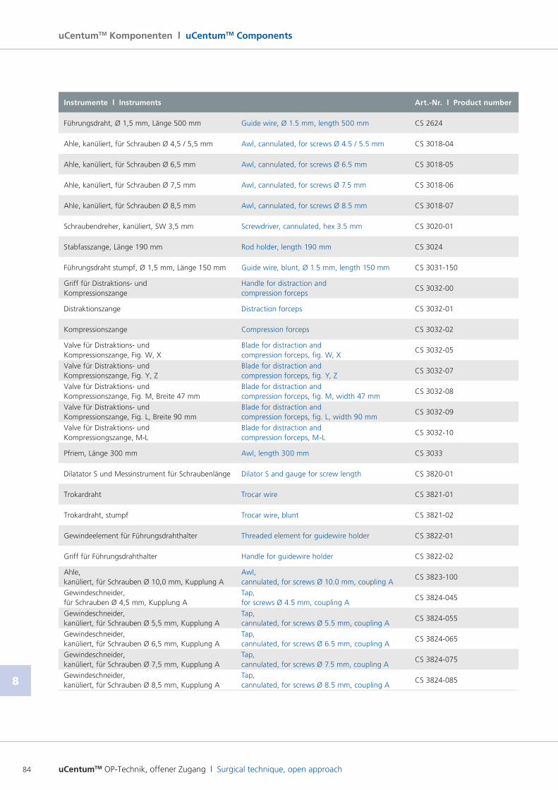
uCentumTM OP-Technik, offener Zugang l Surgical technique, open approach84
8
uCentumTM Komponenten l uCentumTM Components
Instrumente l Instruments Art.-Nr. l Product number
Führungsdraht, Ø 1,5 mm, Länge 500 mm Guide wire, Ø 1.5 mm, length 500 mm CS 2624
Ahle, kanüliert, für Schrauben Ø 4,5 / 5,5 mm Awl, cannulated, for screws Ø 4.5 / 5.5 mm CS 301804
Ahle, kanüliert, für Schrauben Ø 6,5 mm Awl, cannulated, for screws Ø 6.5 mm CS 301805
Ahle, kanüliert, für Schrauben Ø 7,5 mm Awl, cannulated, for screws Ø 7.5 mm CS 301806
Ahle, kanüliert, für Schrauben Ø 8,5 mm Awl, cannulated, for screws Ø 8.5 mm CS 301807
Schraubendreher, kanüliert, SW 3,5 mm Screwdriver, cannulated, hex 3.5 mm CS 302001
Stabfasszange, Länge 190 mm Rod holder, length 190 mm CS 3024
Führungsdraht stumpf, Ø 1,5 mm, Länge 150 mm Guide wire, blunt, Ø 1.5 mm, length 150 mm CS 3031150
Griff für Distraktions und Kompressionszange
Handle for distraction and compression forceps
CS 303200
Distraktionszange Distraction forceps CS 303201
Kompressionszange Compression forceps CS 303202
Valve für Distraktions und Kompressionszange, Fig. W, X
Blade for distraction and compression forceps, fig. W, X
CS 303205
Valve für Distraktions und Kompressionszange, Fig. Y, Z
Blade for distraction and compression forceps, fig. Y, Z
CS 303207
Valve für Distraktions und Kompressionszange, Fig. M, Breite 47 mm
Blade for distraction and compression forceps, fig. M, width 47 mm
CS 303208
Valve für Distraktions und Kompressionszange, Fig. L, Breite 90 mm
Blade for distraction and compression forceps, fig. L, width 90 mm
CS 303209
Valve für Distraktions und Kompressiongszange, ML
Blade for distraction and compression forceps, ML
CS 303210
Pfriem, Länge 300 mm Awl, length 300 mm CS 3033
Dilatator S und Messinstrument für Schraubenlänge Dilator S and gauge for screw length CS 382001
Trokardraht Trocar wire CS 382101
Trokardraht, stumpf Trocar wire, blunt CS 382102
Gewindeelement für Führungsdrahthalter Threaded element for guidewire holder CS 382201
Griff für Führungsdrahthalter Handle for guidewire holder CS 382202
Ahle, kanüliert, für Schrauben Ø 10,0 mm, Kupplung A
Awl, cannulated, for screws Ø 10.0 mm, coupling A
CS 3823100
Gewindeschneider, für Schrauben Ø 4,5 mm, Kupplung A
Tap, for screws Ø 4.5 mm, coupling A
CS 3824045
Gewindeschneider, kanüliert, für Schrauben Ø 5,5 mm, Kupplung A
Tap, cannulated, for screws Ø 5.5 mm, coupling A
CS 3824055
Gewindeschneider, kanüliert, für Schrauben Ø 6,5 mm, Kupplung A
Tap, cannulated, for screws Ø 6.5 mm, coupling A
CS 3824065
Gewindeschneider, kanüliert, für Schrauben Ø 7,5 mm, Kupplung A
Tap, cannulated, for screws Ø 7.5 mm, coupling A
CS 3824075
Gewindeschneider, kanüliert, für Schrauben Ø 8,5 mm, Kupplung A
Tap, cannulated, for screws Ø 8.5 mm, coupling A
CS 3824085
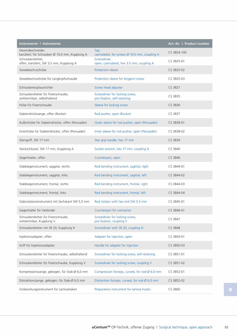
uCentumTM OP-Technik, offener Zugang l Surgical technique, open approach 85
8
Instrumente l Instruments Art.-Nr. l Product number
Gewindeschneider, kanüliert, für Schrauben Ø 10,0 mm, Kupplung A
Tap, cannulated, for screws Ø 10.0 mm, coupling A
CS 3824100
Schraubendreher, offen, kanüliert, SW 3,5 mm, Kupplung A
Screwdriver, open, cannulated, hex 3.5 mm, coupling A
CS 382501
Gewebeschutzhülse Protection sleeve CS 382502
Gewebeschutzhülse für Langkopfschraube Protection sleeve for longarm screw CS 382503
Schraubenkopfausrichter Screw head adjuster CS 3827
Schraubendreher für Fixierschraube, vorklemmbar, selbsthaltend
Screwdriver for locking screw, prefixation, selfretaining
CS 3835
Hülse für Fixierschraube Sleeve for locking screw CS 3836
Stabeindrückzange, offen (Rocker) Rod pusher, open (Rocker) CS 3837
Außenhülse für Stabeindrücker, offen (Persuader) Outer sleeve for rod pusher, open (Persuader) CS 383801
Innenhülse für Stabeindrücker, offen (Persuader) Inner sleeve for rod pusher, open (Persuader) CS 383802
Sterngriff, SW 17 mm Star grip handle, hex 17 mm CS 3839
Steckschlüssel, SW 17 mm, Kupplung A Socket wrench, hex 17 mm, coupling A CS 3840
Gegenhalter, offen Counterpart, open CS 3846
Stabbiegeinstrument, saggital, rechts Rod bending instrument, sagittal, right CS 384401
Stabbiegeinstrument, saggital, links Rod bending instrument, sagittal, left CS 384402
Stabbiegeinstrument, frontal, rechts Rod bending instrument, frontal, right CS 384403
Stabbiegeinstrument, frontal, links Rod bending instrument, frontal, left CS 384404
Stabrotationsinstrument mit Sechskant SW 5,5 mm Rod rotator with hex end SW 5.5 mm CS 384501
Gegenhalter für Verbinder Counterpart for connector CS 384601
Schraubendreher für Fixierschraube, vorklemmbar, Kupplung V
Screwdriver for locking screw, prefixation, coupling V
CS 3847
Schraubendreher mit SR 20, Kupplung H Screwdriver with SR 20, coupling H CS 3848
Injektionsadapter, offen Adapter for injection, open CS 385001
Griff für Injektionsadapter Handle for adapter for injection CS 385003
Schraubendreher für Fixierschraube, selbsthaltend Screwdriver for locking screw, selfretaining CS 385101
Schraubendreher für Fixierschraube, Kupplung V Screwdriver for locking screw, coupling V CS 385102
Kompressionszange, gebogen, für StabØ 6,0 mm Compression forceps, curved, for rodØ 6.0 mm CS 385201
Distraktionszange, gebogen, für StabØ 6,0 mm Distraction forceps, curved, for rodØ 6.0 mm CS 385202
Vorbereitungsinstrument für Laminahaken Preparation instrument for lamina hooks CS 3860
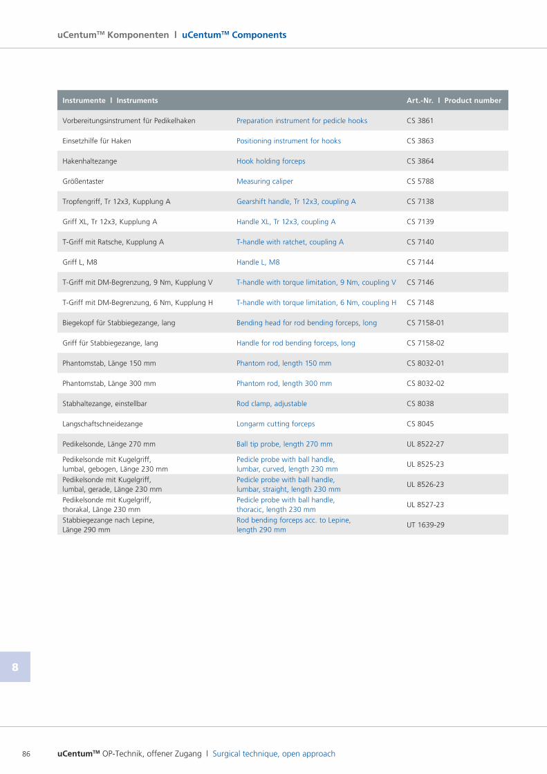
uCentumTM OP-Technik, offener Zugang l Surgical technique, open approach86
8
uCentumTM Komponenten l uCentumTM Components
Instrumente l Instruments Art.-Nr. l Product number
Vorbereitungsinstrument für Pedikelhaken Preparation instrument for pedicle hooks CS 3861
Einsetzhilfe für Haken Positioning instrument for hooks CS 3863
Hakenhaltezange Hook holding forceps CS 3864
Größentaster Measuring caliper CS 5788
Tropfengriff, Tr 12x3, Kupplung A Gearshift handle, Tr 12x3, coupling A CS 7138
Griff XL, Tr 12x3, Kupplung A Handle XL, Tr 12x3, coupling A CS 7139
TGriff mit Ratsche, Kupplung A Thandle with ratchet, coupling A CS 7140
Griff L, M8 Handle L, M8 CS 7144
TGriff mit DMBegrenzung, 9 Nm, Kupplung V Thandle with torque limitation, 9 Nm, coupling V CS 7146
TGriff mit DMBegrenzung, 6 Nm, Kupplung H Thandle with torque limitation, 6 Nm, coupling H CS 7148
Biegekopf für Stabbiegezange, lang Bending head for rod bending forceps, long CS 715801
Griff für Stabbiegezange, lang Handle for rod bending forceps, long CS 715802
Phantomstab, Länge 150 mm Phantom rod, length 150 mm CS 803201
Phantomstab, Länge 300 mm Phantom rod, length 300 mm CS 803202
Stabhaltezange, einstellbar Rod clamp, adjustable CS 8038
Langschaftschneidezange Longarm cutting forceps CS 8045
Pedikelsonde, Länge 270 mm Ball tip probe, length 270 mm UL 852227
Pedikelsonde mit Kugelgriff, lumbal, gebogen, Länge 230 mm
Pedicle probe with ball handle, lumbar, curved, length 230 mm
UL 852523
Pedikelsonde mit Kugelgriff, lumbal, gerade, Länge 230 mm
Pedicle probe with ball handle, lumbar, straight, length 230 mm
UL 852623
Pedikelsonde mit Kugelgriff, thorakal, Länge 230 mm
Pedicle probe with ball handle, thoracic, length 230 mm
UL 852723
Stabbiegezange nach Lepine, Länge 290 mm
Rod bending forceps acc. to Lepine, length 290 mm
UT 163929


uCentumTM OP-Technik, offener Zugang l Surgical technique, open approach88
Operationstechnik l Surgical technique
8
ulrich GmbH & Co. KG l Buchbrunnenweg 12 l 89081 Ulm l GermanyTelefon/Phone: +49 (0)731 96540 l Fax national/international: +49 (0)731 96542705/[email protected] l www.ulrichmedical.com
WS
3801
01
R6/
2017
03