Embed Size (px)
Citation preview

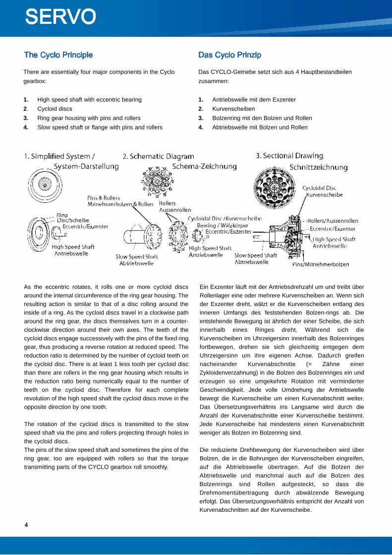
Ein Exzenter läuft mit der Antriebsdrehzahl um und treibt überRollenlager eine oder mehrere Kurvenscheiben an. Wenn sichder Exzenter dreht, wälzt er die Kurvenscheiben entlang desinneren Umfangs des feststehenden Bolzen-rings ab. Dieentstehende Bewegung ist ähnlich der einer Scheibe, die sichinnerhalb eines Ringes dreht. Während sich dieKurvenscheiben im Uhrzeigersinn innerhalb des Bolzenringesfortbewegen, drehen sie sich gleichzeitig entgegen demUhrzeigersinn um ihre eigenen Achse. Dadurch greifennacheinander Kurvenabschnitte (= Zähne einerZykloidenverzahnung) in die Bolzen des Bolzenringes ein underzeugen so eine umgekehrte Rotation mit verminderterGeschwindigkeit. Jede volle Umdrehung der Antriebswellebewegt die Kurvenscheibe um einen Kurvenabschnitt weiter.Das Übersetzungsverhältnis ins Langsame wird durch dieAnzahl der Kurvenabschnitte einer Kurvenscheibe bestimmt.Jede Kurvenscheibe hat mindestens einen Kurvenabschnittweniger als Bolzen im Bolzenring sind.
Die reduzierte Drehbewegung der Kurvenscheiben wird überBolzen, die in die Bohrungen der Kurvenscheiben eingreifen,auf die Abtriebswelle übertragen. Auf die Bolzen derAbtriebswelle und manchmal auch auf die Bolzen desBolzenrings sind Rollen aufgesteckt, so dass dieDrehmomentübertragung durch abwälzende Bewegungerfolgt. Das Übersetzungsverhältnis entspricht der Anzahl vonKurvenabschnitten auf der Kurvenscheibe.
As the eccentric rotates, it rolls one or more cycloid discsaround the internal circumference of the ring gear housing. Theresulting action is similar to that of a disc rolling around theinside of a ring. As the cycloid discs travel in a clockwise patharound the ring gear, the discs themselves turn in a counter-clockwise direction around their own axes. The teeth of thecycloid discs engage successively with the pins of the fixed ringgear, thus producing a reverse rotation at reduced speed. Thereduction ratio is determined by the number of cycloid teeth onthe cycloid disc. There is at least 1 less tooth per cycloid discthan there are rollers in the ring gear housing which results inthe reduction ratio being numerically equal to the number ofteeth on the cycloid disc. Therefore for each completerevolution of the high speed shaft the cycloid discs move in theopposite direction by one tooth.
The rotation of the cycloid discs is transmitted to the slowspeed shaft via the pins and rollers projecting through holes inthe cycloid discs. The pins of the slow speed shaft and sometimes the pins of thering gear, too are equipped with rollers so that the torquetransmitting parts of the CYCLO gearbox roll smoothly.
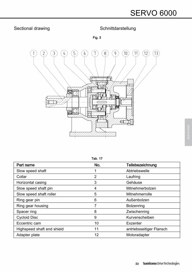
There are essentially four major components in the Cyclogearbox:
1. High speed shaft with eccentric bearing2. Cycloid discs3. Ring gear housing with pins and rollers4. Slow speed shaft or flange with pins and rollers
Das CYCLO-Getriebe setzt sich aus 4 Hauptbestandteilenzusammen:
1. Antriebswelle mit dem Exzenter2. Kurvenscheiben3. Bolzenring mit den Bolzen und Rollen4. Abtriebswelle mit Bolzen und Rollen

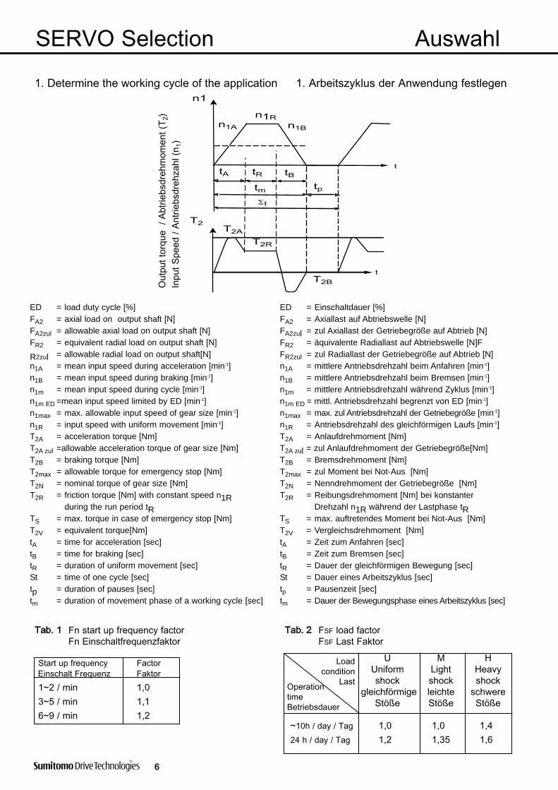
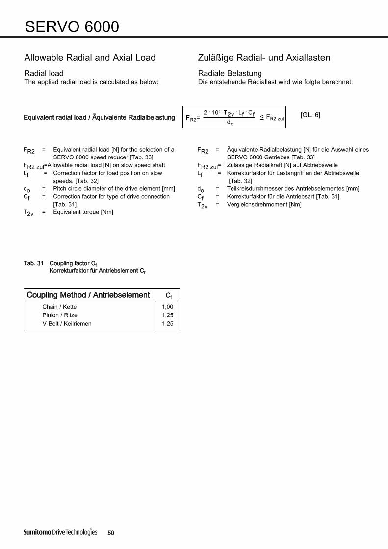
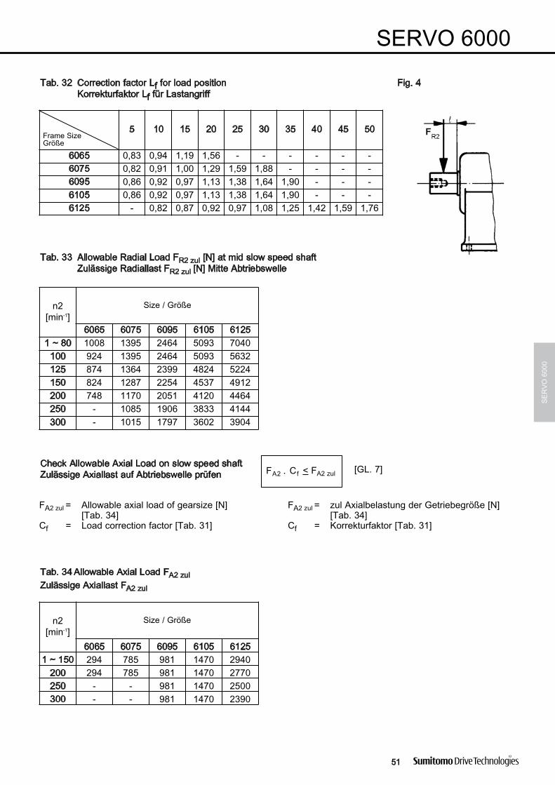
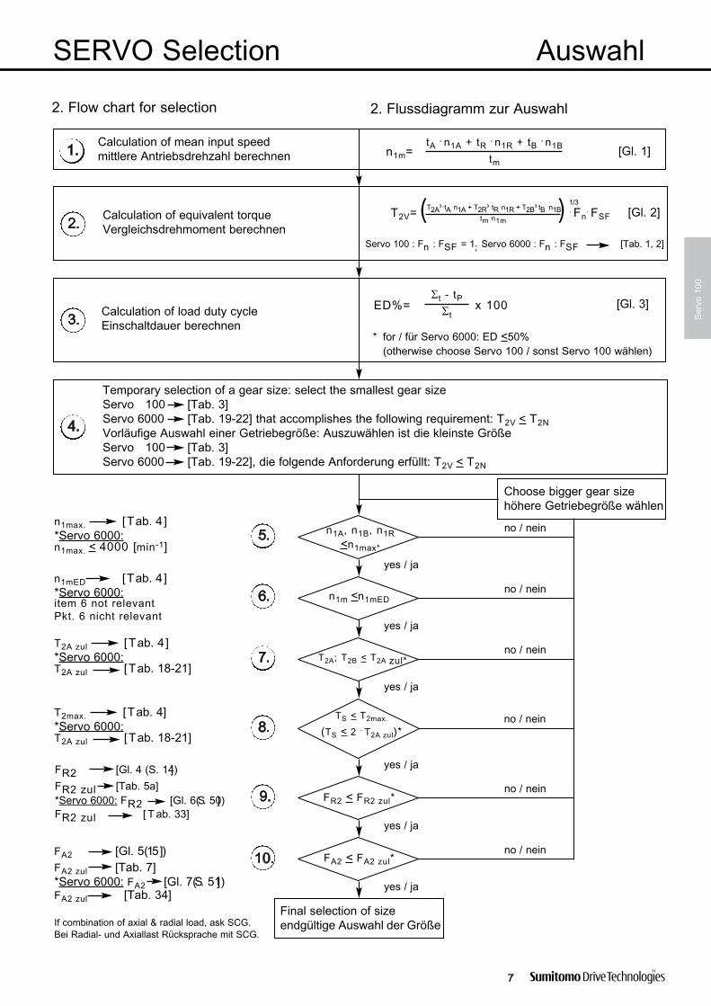
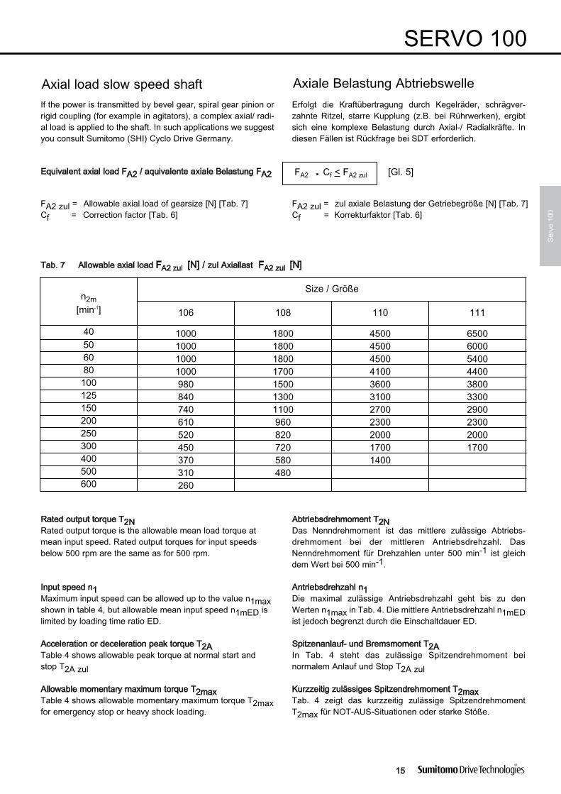
ED = load duty cycle [%] ED = Einschaltdauer [%]FA2 = axial load on output shaft [N] FA2 = Axiallast auf Abtriebswelle [N]FA2zul = allowable axial load on output shaft [N] FA2zul = zul Axiallast der Getriebegröße auf Abtrieb [N]FR2 = equivalent radial load on output shaft [N] FR2 = äquivalente Radiallast auf Abtriebswelle [N]F
R2zul = allowable radial load on output shaft[N] FR2zul = zul Radiallast der Getriebegröße auf Abtrieb [N]n1A = mean input speed during acceleration [min-1] n1A = mittlere Antriebsdrehzahl beim Anfahren [min-1]n1B = mean input speed during braking [min-1] n1B = mittlere Antriebsdrehzahl beim Bremsen [min-1]n1m = mean input speed during cycle [min-1] n1m = mittlere Antriebsdrehzahl während Zyklus [min-1]n1m ED =mean input speed limited by ED [min-1] n1m ED = mittl. Antriebsdrehzahl begrenzt von ED [min-1]n1max = max. allowable input speed of gear size [min-1] n1max = max. zul Antriebsdrehzahl der Getriebegröße [min-1]n1R = input speed with uniform movement [min-1] n1R = Antriebsdrehzahl des gleichförmigen Laufs [min-1]T2A = acceleration torque [Nm] T2A = Anlaufdrehmoment [Nm]T2A zul =allowable acceleration torque of gear size [Nm] T2A zul = zul Anlaufdrehmoment der Getriebegröße[Nm]T2B = braking torque [Nm] T2B = Bremsdrehmoment [Nm]T2max = allowable torque for emergency stop [Nm] T2max = zul Moment bei Not-Aus [Nm]T2N = nominal torque of gear size [Nm] T2N = Nenndrehmoment der Getriebegröße [Nm]T2R = friction torque [Nm] with constant speed n1R T2R = Reibungsdrehmoment [Nm] bei konstanter
during the run period tR Drehzahl n1R während der Lastphase tRTS = max. torque in case of emergency stop [Nm] TS = max. auftretendes Moment bei Not-Aus [Nm]T2V = equivalent torque[Nm] T2V = Vergleichsdrehmoment [Nm]tA = time for acceleration [sec] tA = Zeit zum Anfahren [sec]tB = time for braking [sec] tB = Zeit zum Bremsen [sec]tR = duration of uniform movement [sec] tR = Dauer der gleichförmigen Bewegung [sec]St = time of one cycle [sec] St = Dauer eines Arbeitszyklus [sec]tp = duration of pauses [sec] tp = Pausenzeit [sec]tm = duration of movement phase of a working cycle [sec] tm = Dauer der Bewegungsphase eines Arbeitszyklus [sec]
( )
ΣΣ

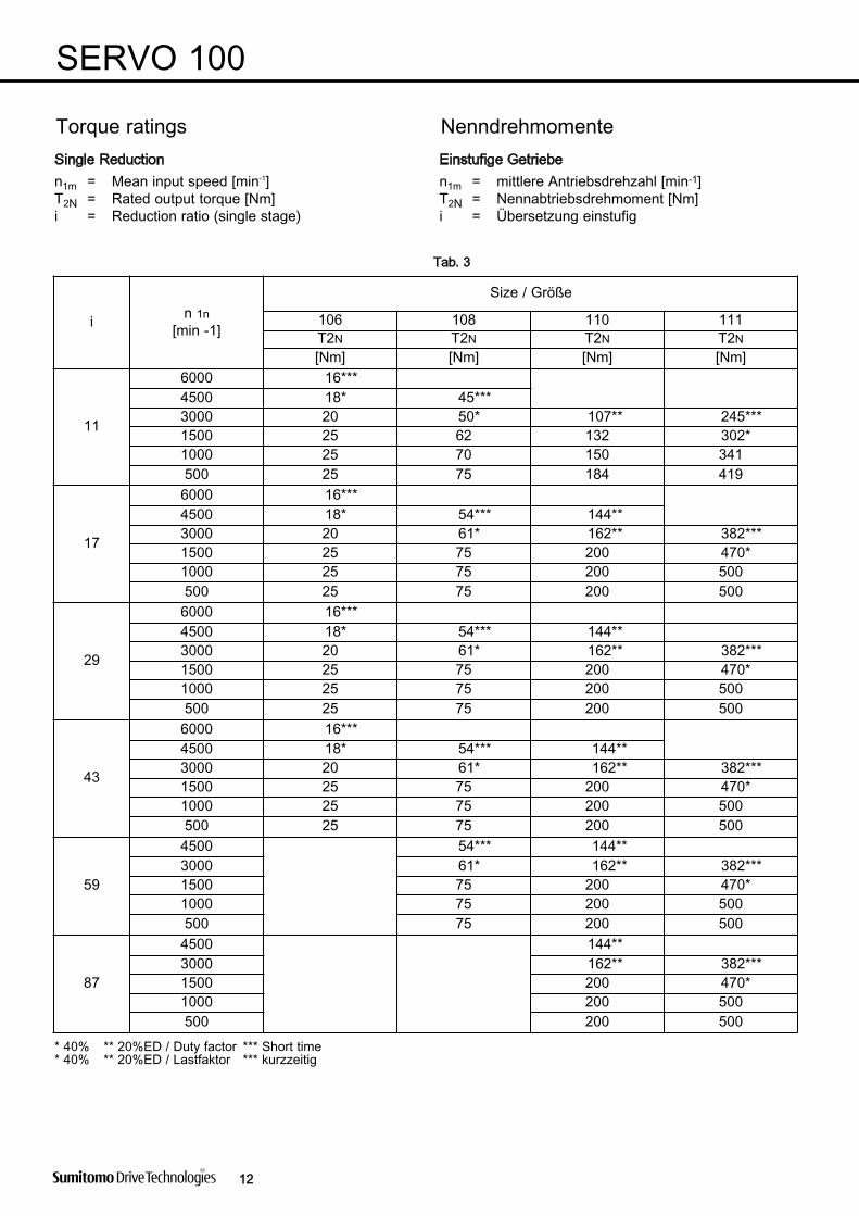
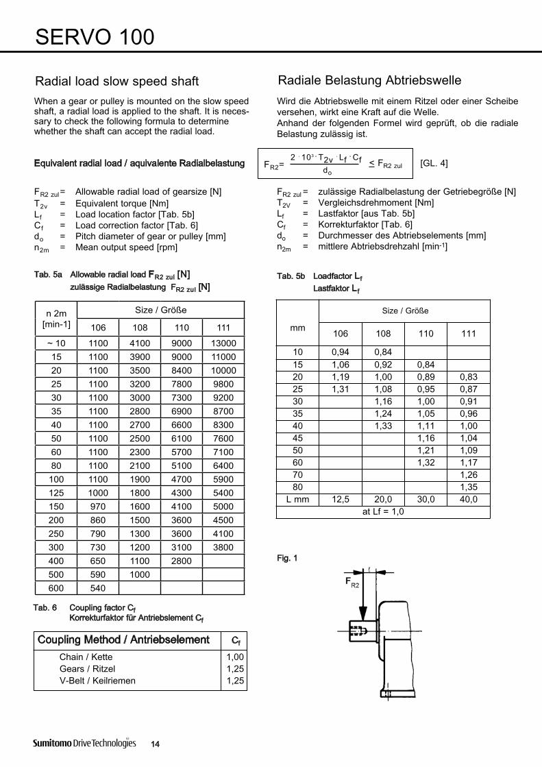
n 2m[min-1]
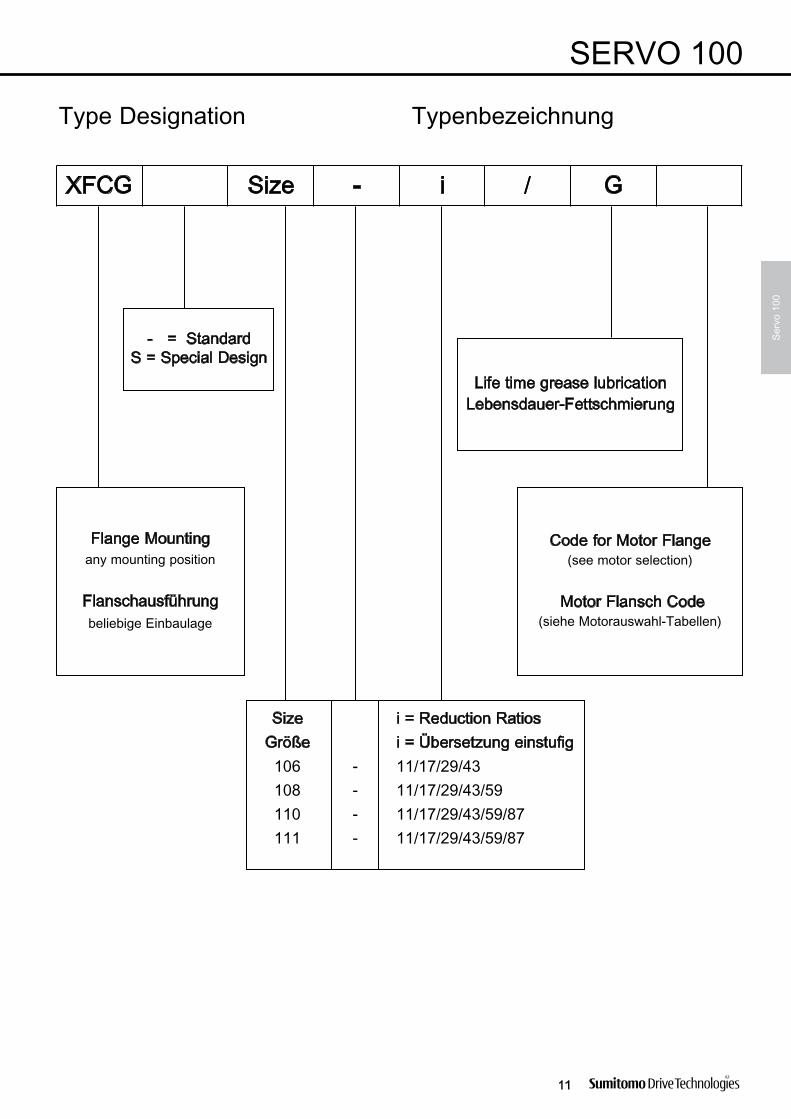
Size / Größe
106 108 110 111
~ 10 1100 4100 9000 1300015 1100 3900 9000 1100020 1100 3500 8400 1000025 1100 3200 7800 980030 1100 3000 7300 920035 1100 2800 6900 870040 1100 2700 6600 830050 1100 2500 6100 760060 1100 2300 5700 710080 1100 2100 5100 6400
100 1100 1900 4700 5900125 1000 1800 4300 5400150 970 1600 4100 5000200 860 1500 3600 4500250 790 1300 3600 4100300 730 1200 3100 3800400 650 1100 2800500 590 1000600 540
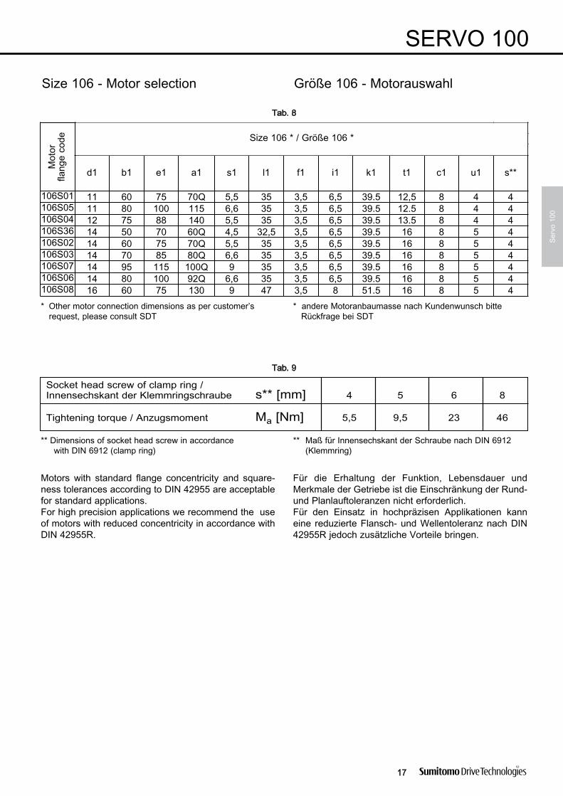
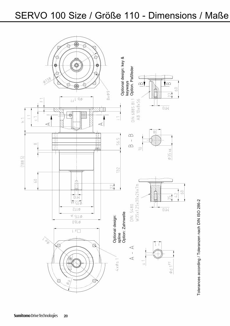
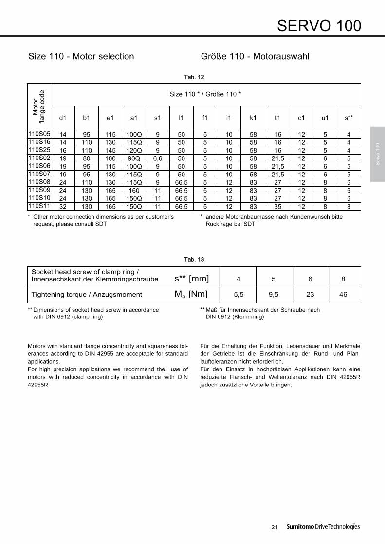
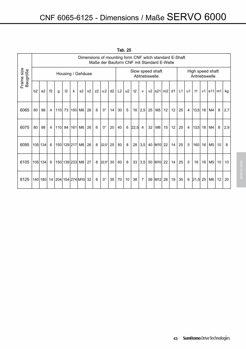
Motors with standard flange concentricity and squareness tol-erances according to DIN 42955 are acceptable for standardapplications.For high precision applications we recommend the use ofmotors with reduced concentricity in accordance with DIN42955R.
Für die Erhaltung der Funktion, Lebensdauer und Merkmaleder Getriebe ist die Einschränkung der Rund- und Plan -lauftoleranzen nicht erforderlich.Für den Einsatz in hochpräzisen Applikationen kann einereduzierte Flansch- und Wellentoleranz nach DIN 42955Rjedoch zusätzliche Vorteile bringen.
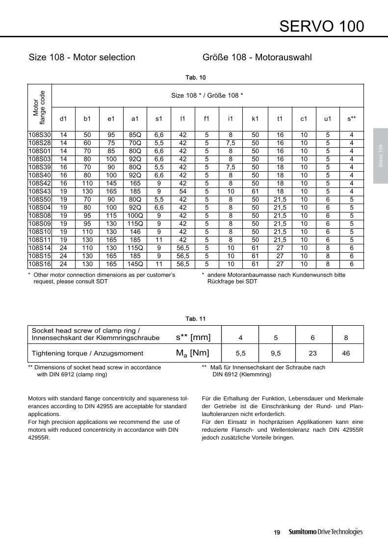
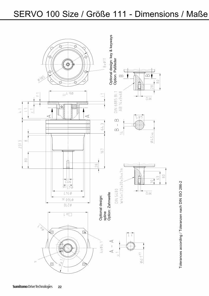
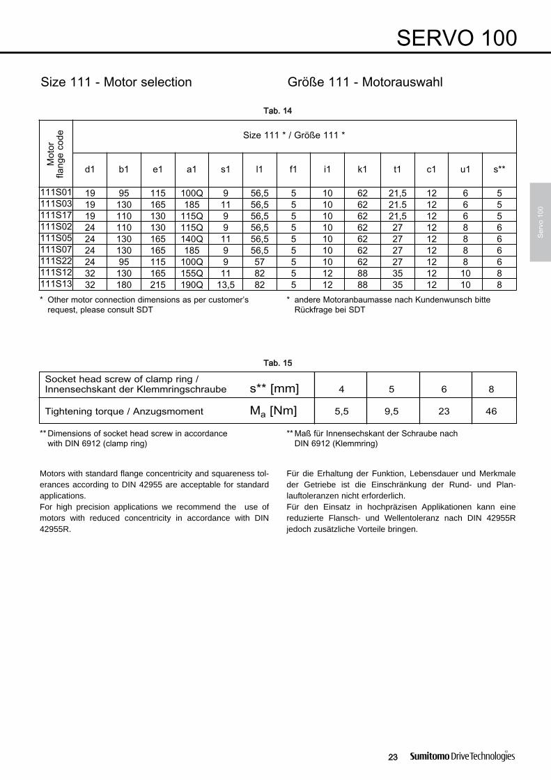
Jedes Getriebe ist lebensdauerfettgeschmiert und kannsofort in Betrieb genommen werden. Die Wellen sind mitRostschutz behandelt, der mit Lösungsmitteln leicht entferntwerden kann. Achtung: Lösungsmittel nicht auf Dichtungenaufbringen!
SERVO Getriebe sind mit Kunststoffharzfarbe lackiert, Farb -ton Sumitomo-Blau.
2. Motoranbau
Bei der spielfreien Verbindung Motorwelle/CYCLO-Antriebswelle mittels Klemmring, ist bei der Montage daraufzu achten, dass die Motorwelle trocken und fettfrei ist. DieInnensechskantschraube des Klemmrings hat Qualität 8.8und muss mit dem vorgeschriebenen An zugsmomentfestgeschraubt werden.
3. Aufsetzen von Kupplungen
Kupplungen, Scheiben, Zahnräder, Kettenräder etc. sind mitHilfe der Gewindebohrung oder durch Anwärmen auf ca.100°C auf die Wellenenden aufzuziehen. Ein Auf pressenoder Aufschlagen darf nicht erfolgen. Für beson dereZusatzeinrichtungen sind die Betriebs an leitungen für dieseTeile zu beachten.
4. Installation
Die Getriebe können in jeder beliebigen Einbaulageeingesetzt werden. Sie sind zur abtriebsseitigen Maschinegenau in der vorgesehenen Einbaulage auszurichten.Die Belastung ist gewährleistet, wenn das Getriebe mit allenBefestigungsschrauben axial gesichert ist. Eine Demontageist nicht zulässig, da das Verdrehspiel eingestellt und dasGetriebe speziell abgedichtet ist.
5. Wartung und Schmierung
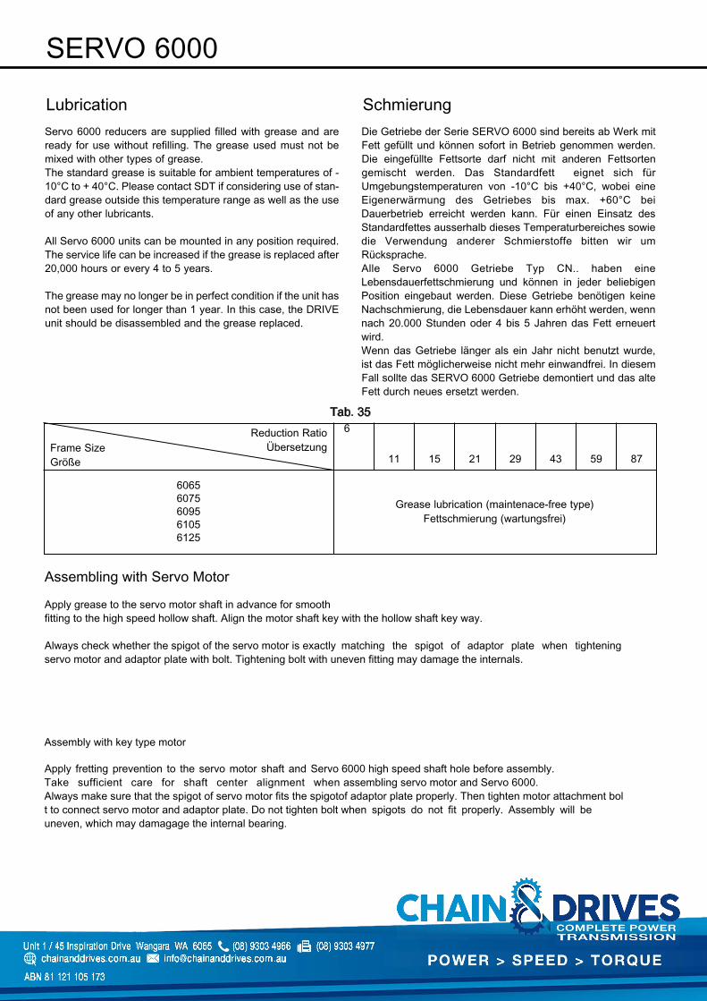
Die Getriebe sind mit Lebensdauerfettschmierungversehen. Die Erneuerung des Fettes soll werksseitignach 20.000 Stunden, spätestens jedoch nach fünfJahren erfolgen.
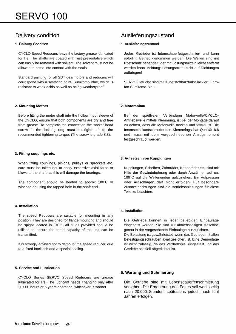
AuslieferungszustandDelivery condition
CYCLO Speed Reducers leave the factory grease lubricatedfor life. The shafts are coated with rust preventative whichcan easily be removed with solvent. The solvent must not beallowed to come into contact with the seals.
Standard painting for all SDT gearmotors and reducers willcorrespond with a synthetic paint, Sumitomo Blue, which isresistant to weak acids as well as being weather proof.
2. Mounting Motors
Before fitting the motor shaft into the hollow input sleeve ofthe CYCLO, ensure that both components are dry and freefrom grease. To complete the connection the socket headscrew in the locking ring must be tightened to therecommended tightening torque. (The screw is grade 8.8).
3. Fitting couplings etc.
When fitting couplings, pinions, pulleys or sprockets etc.care must be taken not to apply excessive axial force orblows to the shaft, as this will damage the bearings.
The component should be heated to approx 100oC orwinched on using the tapped hole in the shaft end.
4. Installation
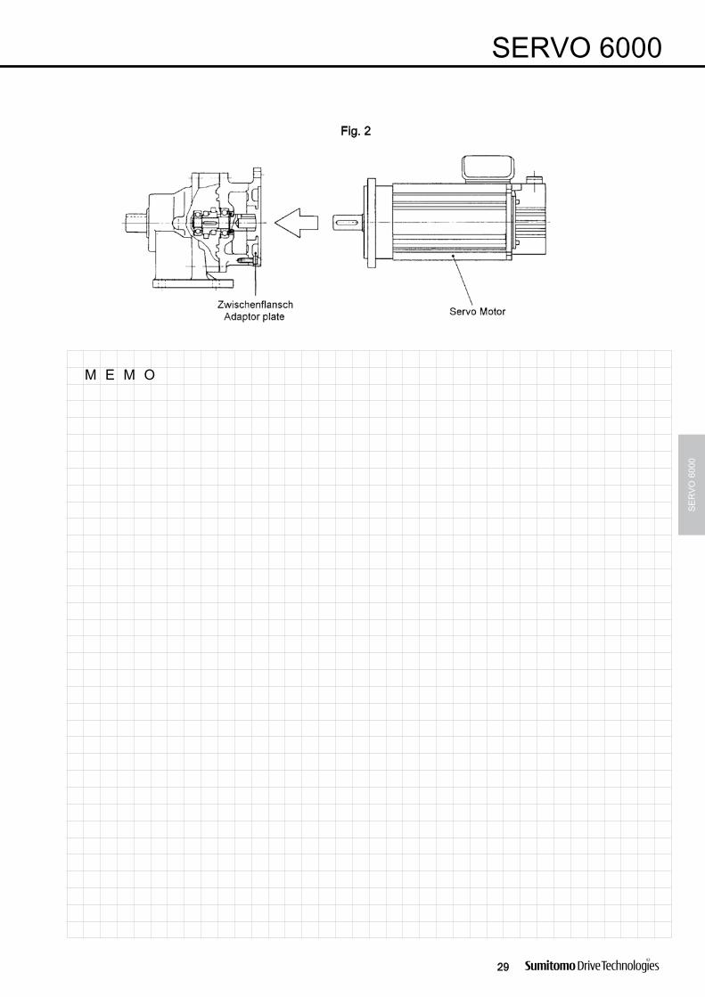
The speed Reducers are suitable for mounting in anyposition. They are designed for flange mounting and shouldbe spigot located in FIG.2. All studs provided should beutilised to ensure the rated capacity of the unit can betransmitted.
It is strongly advised not to demount the speed reducer, dueto a fixed backlash and a special sealing.
5. Service and Lubrication
CYCLO Series SERVO Speed Reducers are greaselubricated for life. The lubricant needs changing only after20,000 hours or 5 years operation, whichever is sooner.


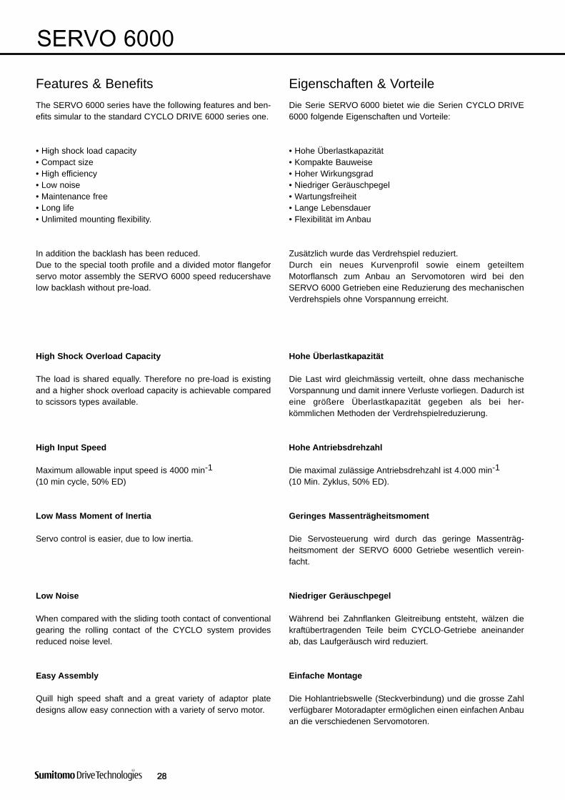
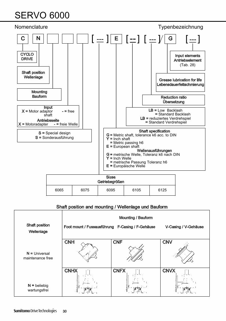
Eigenschaften & VorteileFeatures & BenefitsDie Serie SERVO 6000 bietet wie die Serien CYCLO DRIVE6000 folgende Eigenschaften und Vorteile:
• Hohe Überlastkapazität• Kompakte Bauweise• Hoher Wirkungsgrad• Niedriger Geräuschpegel• Wartungsfreiheit• Lange Lebensdauer• Flexibilität im Anbau
Zusätzlich wurde das Verdrehspiel reduziert.Durch ein neues Kurvenprofil sowie einem geteiltemMotorflansch zum Anbau an Servomotoren wird bei denSERVO 6000 Getrieben eine Reduzierung des mechanischenVerdrehspiels ohne Vorspannung erreicht.
Hohe Überlastkapazität
Die Last wird gleichmässig verteilt, ohne dass mechanischeVorspannung und damit innere Verluste vorliegen. Dadurch isteine größere Überlastkapazität gegeben als bei her -kömmlichen Methoden der Verdrehspielreduzierung.
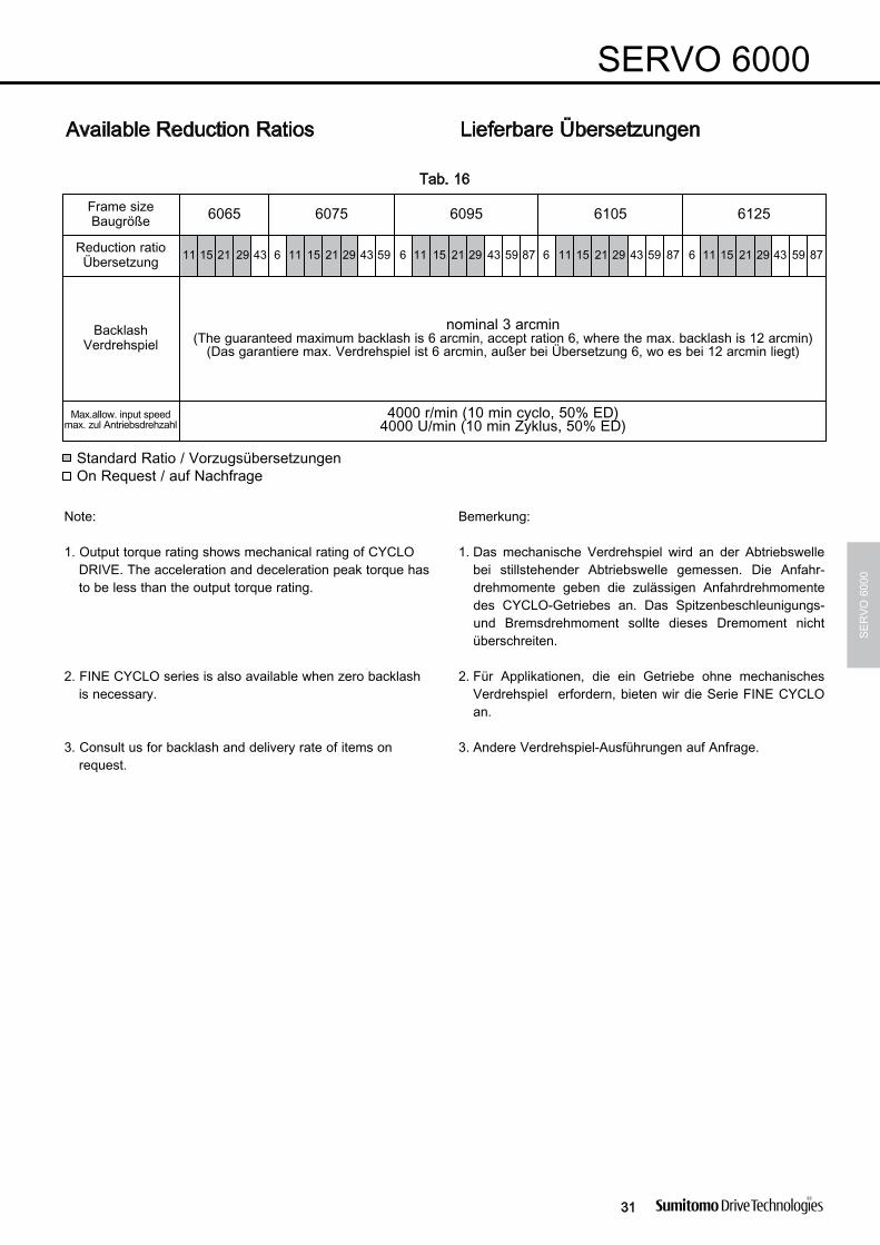
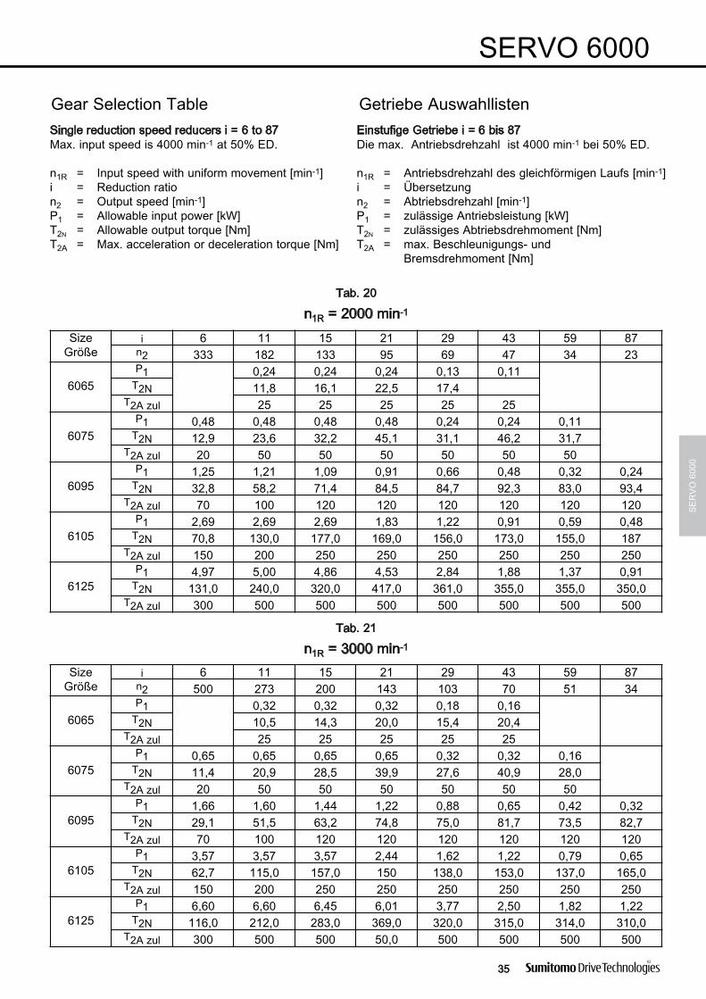
Hohe Antriebsdrehzahl
Die maximal zulässige Antriebsdrehzahl ist 4.000 min-1 (10 Min. Zyklus, 50% ED).
Geringes Massenträgheitsmoment
Die Servosteuerung wird durch das geringe Massen träg -heitsmoment der SERVO 6000 Getriebe wesentlich verein-facht.
Niedriger Geräuschpegel
Während bei Zahnflanken Gleitreibung entsteht, wälzen diekraftübertragenden Teile beim CYCLO-Getriebe aneinanderab, das Laufgeräusch wird reduziert.
Einfache Montage
Die Hohlantriebswelle (Steckverbindung) und die grosse Zahlverfügbarer Motoradapter ermöglichen einen einfachen Anbauan die verschiedenen Servomotoren.
The SERVO 6000 series have the following features and ben-efits simular to the standard CYCLO DRIVE 6000 series one.
• High shock load capacity• Compact size• High efficiency• Low noise• Maintenance free• Long life• Unlimited mounting flexibility.
In addition the backlash has been reduced.Due to the special tooth profile and a divided motor flangeforservo motor assembly the SERVO 6000 speed reducershavelow backlash without pre-load.
High Shock Overload Capacity
The load is shared equally. Therefore no pre-load is existingand a higher shock overload capacity is achievable comparedto scissors types available.
High Input Speed
Maximum allowable input speed is 4000 min-1(10 min cycle, 50% ED)
Low Mass Moment of Inertia
Servo control is easier, due to low inertia.
Low Noise
When compared with the sliding tooth contact of conventionalgearing the rolling contact of the CYCLO system providesreduced noise level.
Easy Assembly
Quill high speed shaft and a great variety of adaptor platedesigns allow easy connection with a variety of servo motor.

α
α
α
α
∅ ∅